WO2010070903A1 - ガス遮断装置 - Google Patents
ガス遮断装置 Download PDFInfo
- Publication number
- WO2010070903A1 WO2010070903A1 PCT/JP2009/006938 JP2009006938W WO2010070903A1 WO 2010070903 A1 WO2010070903 A1 WO 2010070903A1 JP 2009006938 W JP2009006938 W JP 2009006938W WO 2010070903 A1 WO2010070903 A1 WO 2010070903A1
- Authority
- WO
- WIPO (PCT)
- Prior art keywords
- flow rate
- change
- flow volume
- value
- registered
- Prior art date
- Legal status (The legal status is an assumption and is not a legal conclusion. Google has not performed a legal analysis and makes no representation as to the accuracy of the status listed.)
- Ceased
Links
Images
Classifications
-
- F—MECHANICAL ENGINEERING; LIGHTING; HEATING; WEAPONS; BLASTING
- F23—COMBUSTION APPARATUS; COMBUSTION PROCESSES
- F23N—REGULATING OR CONTROLLING COMBUSTION
- F23N5/00—Systems for controlling combustion
- F23N5/18—Systems for controlling combustion using detectors sensitive to rate of flow of air or fuel
- F23N5/184—Systems for controlling combustion using detectors sensitive to rate of flow of air or fuel using electronic means
-
- F—MECHANICAL ENGINEERING; LIGHTING; HEATING; WEAPONS; BLASTING
- F23—COMBUSTION APPARATUS; COMBUSTION PROCESSES
- F23K—FEEDING FUEL TO COMBUSTION APPARATUS
- F23K5/00—Feeding or distributing other fuel to combustion apparatus
- F23K5/002—Gaseous fuel
- F23K5/005—Gaseous fuel from a central source to a plurality of burners
-
- F—MECHANICAL ENGINEERING; LIGHTING; HEATING; WEAPONS; BLASTING
- F23—COMBUSTION APPARATUS; COMBUSTION PROCESSES
- F23N—REGULATING OR CONTROLLING COMBUSTION
- F23N5/00—Systems for controlling combustion
- F23N5/24—Preventing development of abnormal or undesired conditions, i.e. safety arrangements
- F23N5/242—Preventing development of abnormal or undesired conditions, i.e. safety arrangements using electronic means
-
- G—PHYSICS
- G01—MEASURING; TESTING
- G01F—MEASURING VOLUME, VOLUME FLOW, MASS FLOW OR LIQUID LEVEL; METERING BY VOLUME
- G01F15/00—Details of, or accessories for, apparatus of groups G01F1/00 - G01F13/00 insofar as such details or appliances are not adapted to particular types of such apparatus
- G01F15/001—Means for regulating or setting the meter for a predetermined quantity
- G01F15/002—Means for regulating or setting the meter for a predetermined quantity for gases
-
- F—MECHANICAL ENGINEERING; LIGHTING; HEATING; WEAPONS; BLASTING
- F23—COMBUSTION APPARATUS; COMBUSTION PROCESSES
- F23K—FEEDING FUEL TO COMBUSTION APPARATUS
- F23K2900/00—Special features of, or arrangements for fuel supplies
- F23K2900/05001—Control or safety devices in gaseous or liquid fuel supply lines
-
- F—MECHANICAL ENGINEERING; LIGHTING; HEATING; WEAPONS; BLASTING
- F23—COMBUSTION APPARATUS; COMBUSTION PROCESSES
- F23N—REGULATING OR CONTROLLING COMBUSTION
- F23N2231/00—Fail safe
- F23N2231/18—Detecting fluid leaks
-
- F—MECHANICAL ENGINEERING; LIGHTING; HEATING; WEAPONS; BLASTING
- F23—COMBUSTION APPARATUS; COMBUSTION PROCESSES
- F23N—REGULATING OR CONTROLLING COMBUSTION
- F23N2231/00—Fail safe
- F23N2231/20—Warning devices
-
- F—MECHANICAL ENGINEERING; LIGHTING; HEATING; WEAPONS; BLASTING
- F23—COMBUSTION APPARATUS; COMBUSTION PROCESSES
- F23N—REGULATING OR CONTROLLING COMBUSTION
- F23N2237/00—Controlling
- F23N2237/02—Controlling two or more burners
-
- Y—GENERAL TAGGING OF NEW TECHNOLOGICAL DEVELOPMENTS; GENERAL TAGGING OF CROSS-SECTIONAL TECHNOLOGIES SPANNING OVER SEVERAL SECTIONS OF THE IPC; TECHNICAL SUBJECTS COVERED BY FORMER USPC CROSS-REFERENCE ART COLLECTIONS [XRACs] AND DIGESTS
- Y10—TECHNICAL SUBJECTS COVERED BY FORMER USPC
- Y10T—TECHNICAL SUBJECTS COVERED BY FORMER US CLASSIFICATION
- Y10T137/00—Fluid handling
- Y10T137/7722—Line condition change responsive valves
- Y10T137/7758—Pilot or servo controlled
- Y10T137/7761—Electrically actuated valve
Definitions
- the present invention relates to a gas shut-off device, and more particularly to a gas shut-off device that prevents erroneous shut-off due to a use time limit function even when the use flow rate is changed by controlling the flow rate of the instrument itself.
- the flow rate measuring means that outputs a flow rate signal corresponding to the amount of gas passing through, and the increase / decrease of the individual appliances in use when the flow rate signal increases / decreases are estimated.
- Individual device estimation means for outputting the individual calculation flow rate and used time
- individual flow registration means for registering the flow rate of the individual device to be used in advance and outputting the registered individual flow rate and usage time
- individual flow rate for storing the registered individual flow rate
- the storage unit and the estimated individual calculation flow rate of the increased / decreased appliance are not included in the registered individual flow rate of the individual flow rate storage unit, and the individual abnormality signal is output when the increased / decreased duration of the appliance continues for a first predetermined time or more.
- An abnormal flow rate determination unit a notification unit that receives the individual abnormal signal and notifies a warning of an abnormality in the gas flow rate, or a blocking unit that blocks the gas passage, and an estimated number of pieces of the individual appliance estimation unit
- the individual flow rate estimation unit There has been disclosed a gas shut-off device provided with an always individual flow rate registering means for registering an estimated individual calculation flow rate in an individual flow rate storage means (see, for example, Patent Document 1).
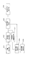
- Reference numeral 101 denotes a flow rate measuring means, which is a flow rate sensor attached to a gas meter.
- Reference numeral 102 denotes an individual appliance estimation means that calculates the flow rate signal of the flow rate sensor 1 as an average flow rate for a fixed measurement period (30 seconds), estimates the increase or decrease of the individual flow rate in use based on the increase or decrease of this average flow rate, The estimated individual calculation flow rate Q and the time used are output.
- the individual device estimation means 102 determines that the increased amount of gas device has been used, and when the average flow rate decreases, determines that the decreased amount of gas device has been stopped, Estimate individual equipment.
- Reference numeral 103 denotes an individual flow rate registration means, which is a setter for inputting in advance the flow rate (Qi) of an individual appliance used in the home.
- Reference numeral 104 denotes individual flow rate storage means for sequentially storing the flow rate (Qi) of the individual appliance of the individual flow rate registration means 103 and the flow rate of the individual flow rate registration means 107 as Q1, Q2, Q3,.
- 105 is an abnormal flow rate determination unit, and the estimated individual flow rate Q output from the individual appliance estimation unit 102 is not included in ⁇ Q1, Q2, Q3,..., Qn ⁇ of the individual flow rate storage unit 104, and the estimated individual flow rate Q Continues for the first predetermined time (10 minutes) or more, the individual abnormality signal E is output.
- Reference numeral 106 denotes a notification means or a cutoff means, which is provided with an LCD or LED for receiving a warning in response to the individual abnormality signal E, or a cutoff valve for blocking the gas passage.
- Reference numeral 107 denotes a constant individual flow rate registration means, which estimates when the estimated individual calculation flow rate Q output from the individual appliance estimation means 102 is equal to or longer than a second predetermined time (3 minutes) and within a first predetermined time (10 minutes). The individual flow rate Q is output to the individual flow rate storage means 104.
- the average flow rate is calculated.
- a change flow rate between the average flow rate and the average flow rate of the previous measurement is obtained to determine whether the change is an increase change or a decrease change, and an estimated individual calculation flow rate Q is obtained by each process. It is determined whether this estimated individual calculation flow rate Q newly appearing as a result of the increase / decrease process is included in the individual flow rate storage means 104 and whether it has been used for the first predetermined time (10 minutes). If it is not included and is used for 10 minutes or more, the notification means or blocking means 106 is operated. If it is not included or is not used for 10 minutes or more, it is judged whether it is an unregistered flow rate, 3 minutes or more, or 10 minutes or less.
- the means 107 performs registration processing in the individual flow rate storage means 104.
- the individual device estimation means 102 If there is an increase in the average flow rate of Qt (for example, Q2 + Q3 as an example) due to the simultaneous use of a plurality of devices, and the usage time is, for example, 7 minutes, that is, the average flow rate decreases after 7 minutes, the individual device estimation means 102 The estimated individual flow rate Qt is output.
- the estimated individual flow rate Qt is registered in the individual flow rate storage unit 104 by the individual flow rate registration unit 107 at all times because the usage time is 3 minutes or more and 10 minutes or less. Thereafter, since it is registered in the individual flow rate storage means 104, even if this flow rate appears for 10 minutes or more, it is not blocked. That is, it is possible to reduce erroneous interruption due to gas appliances that are often started up simultaneously.
- the individual device estimation means 102 outputs the estimated individual flow rate Qk.
- the estimated individual flow rate Qk is registered in the individual flow rate storage unit 104 by the individual flow rate registration unit 107 at all times because the usage time is 3 minutes or more and 10 minutes or less.
- the gas passage is blocked or newly registered as a registered individual flow rate, thereby preventing the gas passage from being erroneously blocked. It has the function.
- the individual device estimation means estimates the individual device, when the device registered as the registered individual flow rate stops using the flow rate gradually changing within the normal range by controlling the flow rate of the device itself. Is different from the individual flow rate at the time of registration, and there is a case where a different registered individual flow rate is deleted by mistake when deleting the registered individual flow rate.
- the water heater may control the gas flow rate according to the temperature deviation in order to keep the set hot water temperature, and the combustion amount may be varied, and the fan heater etc. may have a gas flow rate to keep it at a constant room temperature.
- the amount of combustion is controlled and variable.
- the estimated individual calculation flow rate obtained by the individual device estimation unit at the start of use of the device and registered in the individual flow rate registration unit gradually decreases the gas flow rate by the combustion amount control corresponding to the load fluctuation, and the initial flow rate is gradually increased over time. There may be differences from the estimated individual calculation flow rate.
- the estimated individual calculation flow rate of the individual flow rate registration means is re-registered based on the change amount. If the estimated individual calculation flow rate is changed gradually, the re-registration process of the estimated individual calculation flow rate is not executed. In some cases, the actual flow rate that has been reduced in step 1 and the total value of the registered flow rate may be different. In such a case, the total value of the registered flow rate will be monitored in a state larger than the actual flow rate. The time limit for continuous use is shifted to a short time, leading to erroneous interruption. In other words, there is a problem that erroneous interruption cannot be prevented because monitoring different from the actual use flow rate is performed.
- the present invention solves the above-mentioned problem.
- the registered individual flow rate after deleting the predetermined registered individual flow rate is compared with the average flow rate value obtained by the flow rate calculation means, and the predetermined flow rate or more is obtained.
- the registered individual flow rate can be brought close to the actual used flow rate even in usage modes where the gas flow rate gradually changes with a small change rate.
- the present invention provides a highly safe gas shut-off device without erroneous shut-off.
- the gas shutoff device calculates a flow rate detecting means for measuring a flow rate, and calculates an instantaneous flow rate value by the flow rate calculating means based on the detected value, and obtains an average flow rate based on the obtained instantaneous flow rate.
- An average flow rate calculation means a flow rate change determination means for determining whether or not there is a change in flow rate due to the obtained average flow rate, a flow rate storage means for storing the obtained average flow rate value, and a flow rate at the time of an increase change by the flow rate change judgment means.
- the change is registered by the increased flow registration means, the registered flow that is close to the flow change at the time of decrease is deleted by the flow change determination means, the registered flow is deleted, and the average flow value obtained by the average flow calculation means is replaced and re-registered.
- Abnormality determination means for determining presence / absence of abnormality by the reduced flow rate re-registration means, the monitoring value storage means for storing the determination value for monitoring the use state of the appliance, and the registered flow rate of the flow rate registration means and the determination value of the monitoring value storage means When, and a blocking means for blocking the supply of abnormality determination establishment during gas abnormality determination unit.
- the flow rate registration means when the appliance is used and the appliance flow rate is registered, it is determined that the flow rate change is not made until the appliance is stopped after a slight flow rate change that is not determined as a change in flow rate by the flow rate change determining means. Although it is deleted from the flow rate registration means, when the number of flow rate registrations is one, the flow rate registration value is replaced with the calculated average flow rate and re-registered, so that monitoring is performed with the usage time corresponding to the flow rate of the original instrument.
- the gas shut-off device of the present invention when a plurality of appliances are used and a plurality of appliance flow rates are registered, it is determined that some appliance is stopped by the flow rate change judging means and is deleted from the flow registration means, and the single appliance is used. In this case, by replacing the registered flow rate with the calculated average flow rate and re-registering it, it is possible to monitor the usage time corresponding to the flow rate of the original device, and re-registering the wrongly changed flow rate with the device. However, the flow rate is monitored and the usage time is cut off at an early stage, and the number of unnecessary dispatches of the gas company increases. Can be prevented, and has the effect of high reliability and safety.
- the present invention is a gas shut-off device that monitors the usage status of a plurality of gas appliances and shuts off the supply of gas when an abnormality occurs, the flow rate detecting means for measuring the flow rate, and the flow rate Stores the flow rate calculation means for calculating the instantaneous flow rate value based on the detection value of the detection means, the average flow rate calculation means for obtaining the average flow rate based on the instantaneous flow rate obtained by the flow rate calculation means, and the average flow rate value obtained by the average flow rate calculation means.
- Flow rate storage means a flow rate change determination means for determining that there is a flow rate change when the change flow rate is greater than a predetermined change value from the average flow rate obtained by the average flow rate calculation means and the stored value of the flow rate storage means,
- the increased flow registration means for registering the flow rate change at the time of the increase change by the flow rate change determination means, and the registered flow rate is deleted by deleting the registered flow rate close to the flow rate change at the time of the decrease change by the flow rate change determination means.
- a reduced flow rate re-registration unit that replaces and re-registers the average flow rate value obtained by the average flow rate calculation unit, a monitoring value storage unit that stores a determination value for monitoring the use state of the instrument, and a registered flow rate of the flow rate registration unit, It comprises an abnormality determination means for determining the presence or absence of an abnormality based on the determination value of the monitoring value storage means, and a shut-off means for cutting off the gas supply when the abnormality determination is established by the abnormality determination means.
- the use of the device is detected by the flow rate detection means, converted to the instantaneous flow rate by the flow rate calculation means, and the average flow rate is obtained. Every time the device is used, the flow rate is registered by the increased flow rate registration means, but the device is used. When the device flow rate is registered, it is determined that the flow rate change is not performed by the flow rate change determination unit after a slight flow rate change that is not determined as a flow rate change, and is deleted from the flow rate registration unit. If the number of registered flow rates is 1, the flow rate registration value is replaced with the calculated average flow rate and re-registered, so that it can be monitored in the usage time corresponding to the flow rate of the original device, and the flow rate has changed by a small amount by mistake.
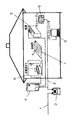
- FIG. 1 is a schematic diagram showing an installation mode of a gas cutoff device and a gas appliance in Embodiment 1 of the present invention
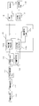
- FIG. 2 is a control block diagram of the gas cutoff device.
- a gas shut-off device 2 is installed at the entrance of the gas supply pipe 1 in each household, and various gas appliances used in each home are installed by branching from the gas pipe 3 after passing through the gas shut-off device 2. Piping to place and gas is supplied.
- a water heater 4 is installed outdoors, and hot water generated by the water heater 4 is installed in a kitchen hot water tap 5, a bath 6 in which a bathtub and a shower device are installed, a living room and the like through a water pipe. It is supplied to the floor heating 7 and forms various usage forms.
- gas is supplied to the gas table 8 installed in the kitchen and the gas fan heater 9 installed in the living room, bedroom, etc., and used as necessary.
- the amount of use is measured by the gas shut-off device 2, and the amount of use is accumulated and stored as a meter reading value.
- the data stored in the gas shut-off device 2 is subjected to predetermined information processing based on a periodic data request command from the gas company, and then the gas fee, gas usage, discount service provided by the gas company, etc. This information is used by consumers and gas companies.
- a gas flow path having a gas inlet and a gas outlet is formed, and a flow rate detecting means 10 for measuring the gas flow rate is provided.
- the flow rate detection means 10 there are various methods as the flow rate detection means 10, and an ultrasonic signal is transmitted from one to the other with a pair of ultrasonic sensors installed in the flow path shown in the present embodiment, and the gas flow rate used is determined from the propagation time.
- Some devices detect the flow rate as an electrical pulse signal.
- a first transmitter / receiver for transmitting or receiving ultrasonic waves and a second transmitter / receiver for receiving or transmitting ultrasonic waves are arranged in opposition to the flow direction, and a control circuit is provided. Can be switched between transmission and reception.
- the flow rate is measured by processing signals from the first transceiver and the second transceiver, and ultrasonic waves are transmitted from upstream to downstream. And it receives with a 2nd transmitter / receiver, and measures propagation time by a time measuring means.
- an ultrasonic signal is transmitted from the downstream to the upstream by the switching means, and the propagation time is measured.
- the flow rate calculation means 11 obtains the flow rate value by multiplying the difference in ultrasonic propagation time between the first transmitter / receiver and the second transmitter / receiver by the flow rate coefficient corresponding to the size of the flow path and the fluid flow state.
- the flow rate is obtained every predetermined cycle as an instantaneous flow rate value.
- the instantaneous flow rate values measured and obtained at predetermined intervals are input to the average flow rate calculation means 12, and a predetermined number of instantaneous flow rate values are collected and calculated as an average flow rate value.
- the flow rate change determining means 13 determines whether or not there is a change in flow rate in the appliance. Whether there is a change in flow rate is determined based on the average flow rate value obtained this time and the previous average flow rate value. Thereafter, the current average flow rate value is stored in the flow rate storage means 14 in time series.
- the flow rate change determination unit 13 compares the average flow rate value calculated by the current average flow rate calculation unit 12 with the stored flow rate value N times before stored in the flow rate storage unit 14, and exceeds the predetermined flow rate value. It is determined whether or not there is a change, and it is determined whether or not the appliance has been used or whether or not the flow rate has changed.
- the flow rate value changes from zero to a predetermined flow rate value, or the average flow rate obtained when the water heater 4 is used while using other appliances and the flow rate storage means 14 Based on whether or not the flow rate change rate or the flow rate change amount is greater than or equal to a predetermined value from the past flow rate stored value, it is determined whether the appliance is used or stopped, or whether the flow rate has changed.
- the flow rate registration means 15 includes an increase flow rate registration means 15a, a decrease flow rate re-registration means 15b, and a registered number measurement means 15d. Each time a change on the flow rate increase side is detected, it is determined that an appliance has been additionally used, and a change in flow rate is newly set as a flow rate registration value each time.
- the abnormality determination means 16 monitors the appliance used at the set registered flow rate.
- the monitoring value storage means 17 stores a time limit value for use time corresponding to each flow rate region, a monitoring judgment value for the maximum use flow rate, or the like. For example, when the hose that supplies gas to a stove or the like is disconnected for some reason, an abnormally large flow rate is generated, but the total flow cutoff value for monitoring such a condition and the maximum use time of the appliance normally
- the monitoring value storage means 17 stores the usage time blocking time limit that defines the usage time limit time corresponding to the case where it has been used for a much longer time.
- the registered flow rate value does not exceed the maximum use flow rate value, or the usage time of the instrument corresponds to the registered flow rate. Monitor whether the time limit for continuous use is exceeded.
- a cutoff signal is sent to the cutoff means 18 to stop the gas supply.
- the notification communication means 19 displays the shut-off state and the shut-off content on a liquid crystal display element or the like, and notifies the center of the gas company that is monitoring the safety of the gas by communication such as a telephone line.
- the flow rate is detected by the flow rate detection means 10.
- the propagation time of the ultrasonic signal is measured as a detected value, and this signal is sent to the flow rate calculation means 11 and converted into an instantaneous flow rate value. Calculated as the average flow value.
- the obtained average flow rate is periodically determined by the flow rate change determination means 13 for the presence or absence of a change in the flow rate in the appliance.
- the flow rate storage means 14 stores a plurality of time-series data after determining the flow rate change.
- Whether there is a change in the flow rate is determined based on the past flow rate stored in the flow rate storage means 14 (for example, the previous or previous time or the flow rate stored value N times before) and the current average flow rate. That is, using the average flow rate value output at a predetermined interval, the use of the appliance or the stoppage of the appliance is determined from the change state, and the flow rate change at the time of change is used as the registered flow rate of the appliance to be used. By newly registering or deleting a registered flow rate that has already been registered, it is possible to accurately set a registered flow rate that corresponds to the appliance used at the time of change.
- the flow rate when the water heater 4 is used, for example, when the past flow rate is zero, the flow rate changes to 1500 L / h or the like, and the change is compared with the current average flow rate and the past average flow rate to determine whether the flow rate has changed. Ask. If the rate of change or the amount of change is greater than or equal to a predetermined value, it is determined that there is a change, and some device is used, and is registered in the flow rate registration means 15. Alternatively, when the water heater 4 is used while the gas table 8 is being used, the flow rate of the gas table 8 is stored in the past flow rate of the flow rate storage means 14, and the flow rate change determination means 13 changes from the current average flow rate and the past flow rate stored value.
- the flow rate is obtained, and similarly, the change rate from the current flow rate, or the change flow rate is registered in the flow rate registration means 15 as having changed when the change flow rate is a predetermined value or more.
- the average flow rate obtained when the flow rate is changed in the flow rate registration unit 15 is input to the increase flow rate registration unit 15a and the decrease flow rate re-registration unit 15b.
- a flow rate increase and determination signal is input by the flow rate change determination means 13
- an increased flow rate with the previous average flow rate is registered.
- the flow rate change judging means 13 determines whether or not there is a decrease change from the past flow rate stored value and the average flow rate, and the decrease change flow rate.
- the flow rate registration means 15 deletes or reduces the closest flow rate registration value among the flow rates registered from the decrease change flow rate.
- the registered flow rate registration count and the reduced flow rate registration count are counted by the registration count measuring means 15d.
- the increased flow rate registration unit 15a of the flow rate registration unit 15 registers the increased flow rate of the gas table 8 and the gas fan heater 9, and further registers the flow rate of the water heater 4.
- the flow rate of use of the water heater 4 is changed and the average flow rate value at this time is registered in the flow rate register 15 as a registered flow rate.
- the combustion amount that is, the gas flow rate is controlled in a decreasing direction by the proportional control. Change continues for a long time. In such a case, since the flow rate does not change, the registered value of the flow rate registration means 15 does not change.
- the flow rate change determining unit 13 determines that the flow rate is decreasing, and the reduced flow rate re-registering unit 15b deletes the registered flow rate corresponding to the decreased flow rate. At this time, the number of registered flow rates is measured. If the number of registered flow rates is one, the newly determined average flow rate is replaced with the flow rate registered as a new flow rate and re-registered due to a change in the instrument.
- the flow rate of the gas table 8 or the gas fan heater 9 is actually used, but as a result of the flow rate decrease that does not change the flow rate of the hot water heater 4, the flow rate value registered and the reduced flow rate value do not match, and some device It erroneously determines that there is a flow rate, and prevents a new flow rate from being registered.
- the abnormality determination means 16 becomes a target of the registered flow rate when compared with the set value of the monitoring value storage means 17, and the instrument that is actually used
- the device used may be monitored at a registered flow rate that is larger than the flow rate of the product, and the continuous use time limit will not be monitored in a time shorter than the flow rate of the device actually used. Therefore, it is possible to eliminate the inconvenience that the blocking means 18 is blocked.
- the abnormality determination unit 16 refers to the corresponding use time limit time in the monitoring value storage unit 17 with the reset registered flow rate, and monitors the used appliance.
- the monitoring time elapses and an abnormality occurs, safety is ensured by operating the shut-off means 18 and stopping the gas supply.
- the gas shutoff device according to the present invention is intended to optimize the function of limiting the usage time of appliances whose usage changes slightly, and is applicable to appliance monitoring devices such as water meters and digital power meters in general. Applicable.
Landscapes
- Engineering & Computer Science (AREA)
- Chemical & Material Sciences (AREA)
- Combustion & Propulsion (AREA)
- Mechanical Engineering (AREA)
- General Engineering & Computer Science (AREA)
- Physics & Mathematics (AREA)
- Fluid Mechanics (AREA)
- General Physics & Mathematics (AREA)
- Measuring Volume Flow (AREA)
- Feeding And Controlling Fuel (AREA)
Abstract
器具の流量の適切な登録を行い、使用時間制限機能の適切化を図ることを目的とする。本発明のガス遮断装置は、流量を計測する流量検出手段と、検出値により瞬時流量値を流量演算手段で演算し、求めた瞬時流量により平均流量を求める平均流量演算手段と、求めた平均流量により流量の変化有か否かを判定する流量変化判定手段と、求めた平均流量値を格納する流量格納手段と、流量変化判定手段で増加変化時流量変化分を増加流量登録手段により登録し、流量変化判定手段で減少変化時流量変化分に近い登録流量を削除し当該登録流量が削除され平均流量演算手段で求めた平均流量値に置換し再登録する減少流量再登録手段と、登録流量と監視判定値とから異常判定手段で異常と判定時ガス供給を遮断手段で遮断する。
Description
本発明は、ガス遮断装置に関し、特に器具自体の流量の制御により使用流量が変化した場合でも使用時間制限機能による誤遮断を防止するガス遮断装置に関するものである。
従来、この種のガス遮断装置としては、通過ガス量に対応した流量信号を出力する流量測定手段と、流量信号が増減したときに使用中の個別器具の増減を推定し、増減した器具の推定個別演算流量と使用した時間を出力する個別器具推定手段と、あらかじめ使用する個別器具の流量を登録し登録個別流量と使用時間とを出力する個別流量登録手段と、登録個別流量を記憶する個別流量記憶手段と、増減した器具の推定個別演算流量が個別流量記憶手段の登録個別流量に含まれず、かつ増減した器具の継続使用時間が第1の所定時間以上続いた場合に個別異常信号を出力する異常流量判定部と、前記個別異常信号を受信して、ガス流量の異常を警告報知する報知手段、またはガス通路を遮断する遮断手段と、個別器具推定手段の器具の推定個別演算流量が個別流量記憶手段の登録個別流量に含まれず、かつ個別器具推定手段の器具の使用した時間が第2の所定時間よりも長く第1の所定時間よりも短い場合に個別流量推定手段の推定個別演算流量を個別流量記憶手段に登録する常時個別流量登録手段とを備えたガス遮断装置が開示されている(例えば、特許文献1参照)。
この特許文献1のガス遮断装置について図3を用いて簡単に構成を説明すると、101は流量測定手段で、ガスメーターに取り付けられた流量センサである。102は個別器具推定手段で、流量センサ1の流量信号を一定計測期間(30秒)の平均流量として演算し、この平均流量の増減をもとに使用中の個別流量の増減を推定し、増減した器具の推定個別演算流量Qと使用した時間とを出力する。この個別器具推定手段102は、平均流量が増加した場合はその増加分のガス器具が使用されたと判断し、平均流量が減少した場合はその減少分のガス器具を止めたと判断し、使用中の個別器具を推定する。103は個別流量登録手段で、その家庭で使用する個別器具の流量(Qi)を予めインプットする設定器である。104は個別流量記憶手段で、個別流量登録手段103の個別器具の流量(Qi)と常時個別流量登録手段107の流量を順次Q1,Q2,Q3,・・・,Qnと記憶する。105は異常流量判定部で、個別器具推定手段102から出力される推定個別流量Qが個別流量記憶手段104の{Q1,Q2,Q3,・・・,Qn}に含まれず、かつ推定個別流量Qが第1の所定時間(10分)以上続けば、個別異常信号Eを出力する。106は報知手段あるいは遮断手段で、個別異常信号Eを受けて警告報知するLCDやLED、またはガス通路を遮断する遮断弁を備えている。107は常時個別流量登録手段で、個別器具推定手段102から出力される推定個別演算流量Qが第2の所定時間(3分)以上かつ第1の所定時間(10分)以内の場合に前記推定個別流量Qを個別流量記憶手段104に出力する。
次に従来例の構成の動作を説明する。流量測定手段101の流量信号をもとに平均流量を計算する。この平均流量と前前回の計測の平均流量との変化流量を求め、増加の変化か減少の変化かを判断し、それぞれの処理により推定個別演算流量Qを求める。増加減少処理の結果あらたに出現したこの推定個別演算流量Qが、個別流量記憶手段104に含まれるかどうかかつ、第1の所定時間(10分間)使用されたかどうかの判断をする。含まれずかつ、10分以上使用されれば報知手段または遮断手段106を動作させる。含まれずまたは、10分以上使用されなければ、それぞれ未登録流量か、3分以上使用されたか、10分以下の使用時間であるかを判断し、すべてに合致していれば、常時個別流量登録手段107は、個別流量記憶手段104に登録の処理を行なう。
いま、複数器具の同時使用により、Qt(例としてQ2+Q3)という平均流量の増加があり、使用時間がたとえば7分、すなわち、7分後に平均流量が減少した場合には、個別器具推定手段102により推定個別流量Qtが出力される。この推定個別流量Qtは、常時個別流量登録手段107により使用時間が3分以上かつ10分以下ということで個別流量記憶手段104に登録される。以降、個別流量記憶手段104に登録されるので、この流量が10分以上出現しても、遮断することはない。すなわち、同時立ち上げするケースの多いガス器具による誤遮断を低減することができる。また、買い替え器具等による、新しい個別流量Qk(3分以上10分以下)があった場合には、個別器具推定手段102により推定個別流量Qkが出力される。この推定個別流量Qkは、常時個別流量登録手段107により使用時間が3分以上かつ10分以下ということで個別流量記憶手段104に登録される。
以降、個別流量記憶手段104に登録されるので、この流量が10分以上出現しても遮断されることはない。それぞれの家庭で使用する個別器具をあらかじめ記憶し、個別器具以外の流量によるガス漏れによる事故を未然に防ぐことができ、器具の同時立ち上げあるいは器具の買い替え等による誤遮断を防止できる。
上記従来の構成では、個別流量記憶手段に登録された流量以外の流量が新たに検出された場合のガス通路の遮断、あるいは登録個別流量として新たに登録することでガス通路の誤遮断を防止するという機能は有している。しかしながら、個別器具推定手段は個別器具を推定する際、登録個別流量として登録している器具が当該器具自身の流量の制御により正常範囲内で流量が少しずつ変化した状態で使用を停止した場合には登録時の個別流量と異なる値となり、登録個別流量を削除する際に間違って違う登録個別流量を削除してしまうケースがある。この場合、登録個別流量の少ない方を削除し、多い方が残ってしまうと、器具を連続して使用可能な制限時間が短縮されることになり、予想以上に短い時間でガス遮断弁が作動してガスの供給を停止してしまうことになる。反対に登録個別流量の多い方を削除し、少ない方が残ってしまうと、連続使用の制限時間が延長されることになり、使用流量の大きな器具を使用する場合等は安全性の面で課題を有することになる。
例えばシャワーなどを使用するとき給湯器は設定湯温に保つ為にガス流量を温度偏差に応じて制御し燃焼量を可変する場合があり、またファンヒータ等は一定室温に保つ為にガス流量を制御し燃焼量を可変する場合がある。このような場合、器具の使用開始時に個別器具推定手段で求め個別流量登録手段に登録された推定個別演算流量が負荷変動に対応した燃焼量制御によりガス流量が徐々に減少し時間経過と共に初期の推定個別演算流量と差異が生じる場合がある。通常、複数器具使用中に他方の器具が使用停止或いは大きな流量変化が発生すると、その変化量に基づいて個別流量登録手段の推定個別演算流量を登録し直すが、上記使用形態の如く小さい変化率で徐々に変化する場合は推定個別演算流量の登録し直し処理が実行されず、器具使用停止や器具使用追加のタイミングで推定個別演算流量の登録し直し処理を行った場合に、燃焼量制御等で減少した実際の流量と登録された流量の合計値とが異なる場合があり、このような場合、登録された流量の合計値が実際の流量より多めの状態で監視されることになり、器具の連続使用の制限時間が短めにシフトされ誤遮断に繋がることになる。つまり、実使用流量とは異なった監視を行うため誤遮断を防止できないという課題を有していた。
本発明は、上記課題を解決するもので、器具使用停止を検出したとき、所定の登録個別流量を削除した後の登録個別流量と流量演算手段で求められる平均流量値とを比較し所定以上の差が有る場合にその差分データに基づいて登録個別流量を補正することで、小さい変化率でガス流量が徐々に変化するような使用形態においても登録個別流量を実際の使用流量に近づけることができ、誤遮断がなく、安全性の高いガス遮断装置を提供するものである。
上記従来の課題を解決するために、本発明のガス遮断装置は、流量を計測する流量検出手段と、検出値により瞬時流量値を流量演算手段で演算し、求めた瞬時流量により平均流量を求める平均流量演算手段と、求めた平均流量により流量の変化が有か否かを判定する流量変化判定手段と、求めた平均流量値を格納する流量格納手段と、流量変化判定手段で増加変化時流量変化分を増加流量登録手段により登録し、流量変化判定手段で減少変化時流量変化分に近い登録流量を削除し登録流量が削除され平均流量演算手段で求めた平均流量値に置換し再登録する減少流量再登録手段と、器具の使用状態を監視する判定値を記憶する監視値記憶手段と、流量登録手段の登録流量と監視値記憶手段の判定値とにより異常の有無を判定する異常判定手段と、異常判定手段で異常判定成立時ガスの供給を遮断する遮断手段とからなる。
上記発明によれば、器具が使用され器具流量が登録されている時、流量変化判定手段で流量変化と判定されない微少な流量変化が継続した後何らかの器具が使用停止された時初めて流量変化と判断され流量登録手段より削除されるが、流量登録数が1個の場合、求めた平均流量で流量登録値を置換し再登録することにより、本来の器具の流量に対応した使用時間で監視することができ、誤って微少流量変化した流量を器具と間違って再登録しその流量を使用時間監視し早期に使用時間遮断し、ガス事業者の不要な出動回数が増大したり、暖房器具のように本来長時間使用可能であるのに短時間で停止し使い勝手の低下するのを防止することができ、かつ信頼性や安全性の高い効果がある。
本発明のガス遮断装置は、複数器具使用し複数の器具流量が登録されている時、流量変化判定手段で何らかの器具が使用停止と判断され流量登録手段より削除され使用器具が単一となった場合、求めた平均流量で流量登録値を置換し再登録することにより、本来の器具の流量に対応した使用時間で監視することができ、誤って微少流量変化した流量を器具と間違って再登録しその流量を使用時間監視し早期に使用時間遮断し、ガス事業者の不要な出動回数が増大したり、暖房器具のように本来長時間使用可能であるのに短時間で停止し使い勝手の低下するのを防止することができ、かつ信頼性や安全性の高い効果がある。
本発明は上記目的を達成する為に、複数のガス器具の使用状況を監視するとともに、異常発生時にガスの供給を遮断するガス遮断装置であって、流量を計測する流量検出手段と、前記流量検出手段の検出値により瞬時流量値を演算する流量演算手段と、前記流量演算手段で求めた瞬時流量により平均流量を求める平均流量演算手段と、前記平均流量演算手段で求めた平均流量値を格納する流量格納手段と、前記平均流量演算手段で求めた平均流量と前記流量格納手段の格納値とから変化流量が予め定めた変化値より大きいとき流量変化有と判定する流量変化判定手段と、前記流量変化判定手段で増加変化時の流量変化分を登録する増加流量登録手段と、前記流量変化判定手段で減少変化時の流量変化分に近い登録流量を削除し登録流量が削除され前記平均流量演算手段で求めた平均流量値に置換し再登録する減少流量再登録手段と、器具の使用状態を監視する判定値を記憶する監視値記憶手段と、流量登録手段の登録流量と監視値記憶手段の判定値とにより異常の有無を判定する異常判定手段と、前記異常判定手段で異常判定成立時ガスの供給を遮断する遮断手段とからなる。
そして、器具使用を流量検出手段で検出し、流量演算手段で瞬時流量に換算し、平均流量を求めるが、器具が使用されるたび、増加流量登録手段により流量登録されるが、器具が使用され器具流量が登録されている時、流量変化判定手段で流量変化と判定されない微少な流量変化が継続した後何らかの器具が使用停止された時初めて流量変化と判断され流量登録手段より削除されるが、流量登録数が1個の場合、求めた平均流量で流量登録値を置換し再登録することにより、本来の器具の流量に対応した使用時間で監視することができ、誤って微少流量変化した流量を器具と間違って再登録しその流量を使用時間監視し早期に使用時間遮断し、ガス事業者の不要な出動回数が増大したり、暖房器具のように本来長時間使用可能であるのに短時間で停止し使い勝手の低下するのを防止することができ、かつ安全性が高い。
(実施の形態1)
図1は本発明の実施の形態1におけるガス遮断装置とガス器具の設置形態を示す概略図、図2は同ガス遮断装置の制御ブロック図である。
図1は本発明の実施の形態1におけるガス遮断装置とガス器具の設置形態を示す概略図、図2は同ガス遮断装置の制御ブロック図である。
各家庭のガス供給管1の入口部分にガス遮断装置2が設置され、このガス遮断装置2を経由した後のガス配管3から分岐して、各家庭で使用する種々のガス器具が設置された場所まで配管され、ガスが供給される。例えば、屋外には給湯器4が設置され、この給湯器4で生成される湯が水配管を介して台所の給湯栓5、浴槽やシャワー装置が設置された風呂6、リビング等に設置された床暖房7に供給され、種々の使用形態を形成している。
また、屋内にあっては、台所に設置されたガステーブル8、リビングや寝室等に設置されたガスファンヒータ9にガスが供給され、必要に応じて適宜使用される。
そして、設置されたガス器具が使用されガスの消費が発生するとガス遮断装置2でその使用量が計測され、その使用量が検針値として累積記憶されている。このガス遮断装置2に記憶されたデータはガス事業者からの定期的なデータ要求指令に基づいて所定の情報処理を行った後、ガス料金やガス使用量あるいはガス事業者が提供する割引サービス等の情報として需要家及びガス事業者に使用される。
そして、ガス遮断装置2には、ガス入口とガス出口を有したガス流路が形成され、ガス流量を計測する流量検出手段10が設けられている。なお、流量検出手段10としては種々の方式があり、本実施の形態で示す流路内に設置された一対の超音波センサで超音波信号を一方から他方に発信しその伝搬時間より使用ガス流量を検出するものや、流路内に熱線式センサを設け流れにより変化するインピーダンスより流量を求めるもの、さらには計量膜によりガス量を検出し計量膜の機械的動作を磁石とリードスイッチあるいは磁気抵抗素子等により電気的パルス信号として流量を検出するものがある。
そこで、超音波センサを用いた流量検出手段10について簡単に説明すると、超音波を送信または受信する第1送受信器と受信または送信する第2送受信器が流れ方向に対抗して配置され、制御回路によって送受信の切り換えが可能になっている。この第1送受信器と第2送受信器の信号を処理して流量を計測するもので、上流から下流に超音波を送信する。そして第2送受信器で受信し計時手段で伝搬時間を計測する。
次に、切換手段で下流から上流に向かって超音波信号を送信し、伝搬時間を計測する。そして、第1送受信器と第2送受信器との超音波の伝搬時間差から流路の大きさや流体の流れ状態に対応した流量係数を掛けて流量演算手段11で流量値を求める。流量は瞬時流量値として予め定めた周期毎に求められる。
そして、所定周期毎に計測し求めた瞬時流量値は平均流量演算手段12に入力され、所定個数の瞬時流量値を集合して平均流量値として算出される。この平均流量値により流量変化判定手段13で器具における流量の変化の有無を判定する。今回求めた平均流量値と前回の平均流量値とにより流量の変化の有無判定が行われる。その後今回の平均流量値は時系列的に流量格納手段14に格納される。即ち流量変化判定手段13では、今回平均流量演算手段12で算出された平均流量値と流量格納手段14に格納されたN回前の格納流量値とを比較して、予め定めた流量値以上の変化があるか否かを判定し、器具の使用開始の有無、或いは流量の変化の有無を判断する。例えば、需要家が給湯器4を使用すると流量値はゼロから所定の流量値まで変化、あるいは他の器具を使用中に給湯器4等が使用されると求めた平均流量と流量格納手段14の過去の流量格納値とから流量変化率あるいは流量変化量が所定以上あったか否かで器具の使用若しくは停止、または流量の変化の有無を判断する。
そして、流量変化判定手段13で流量の変化が検出されると、器具の使用開始か、あるいは器具の使用停止かが判断される。具体的には、器具が使用された場合は流量の変化分が流量登録手段15により登録流量値として設定される。ここで流量登録手段15は、増加流量登録手段15aと減少流量再登録手段15bと登録数計測手段15dとからなる。流量増加側の変化が検出される度に器具が追加使用されたと判定して、都度流量の変化分を新規に流量登録値として設定する。反対に、器具の使用が停止された場合は流量登録手段15に登録されている登録流量値のうち流量の変化分に近い登録流量値をその器具が停止されたと判定し流量登録値より削除する。この削除処理も同様に、流量減少側の変化が検出される度に器具の使用が停止されたと判断して都度、登録流量値の削除処理を実行する。
そして、異常判定手段16は、設定された登録流量で使用器具の監視を行う。監視値記憶手段17は、流量域毎に対応した使用時間の制限時間値、あるいは使用最大流量の監視判定値等が記憶されている。例えばストーブ等へガスを供給するホースが何らかの原因で外れた時、異常な大流量が発生するが、そのような状態を監視するための合計流量遮断値や、器具の通常使用する最大使用時間よりはるかに長く使用された場合に対応して使用時間の制限時間を規定した使用時間遮断の制限時間等を監視値記憶手段17に記憶している。この設定値と流量登録手段15の登録流量値とを異常判定手段16で比較判定することで、登録流量値が使用最大流量値を超えていないか、或いは器具の使用時間が登録流量に対応した連続使用の制限時間を超えていないか等監視する。この異常判定手段16で異常成立と判定した時、遮断手段18に遮断信号を送ってガス供給を停止する。また、報知通信手段19は、遮断状態や遮断内容を液晶表示素子等に表示すると共にガスの安全監視を行っているガス事業者のセンターに電話回線等の通信により通報する。
次に、以上のように構成されたガス遮断装置2の動作を説明する。需要家宅で保有しているガス器具、例えば給湯器4やガスファンヒータ9等が使用されるとその流量を流量検出手段10で検出する。例えば超音波センサを用いた場合は超音波信号の伝搬時間が検出値として計測され、この信号が流量演算手段11に送られて瞬時流量値として換算され、平均流量演算手段12で所定個数毎の平均流量値として演算される。求められた平均流量は流量変化判定手段13で定期的に器具における流量の変化の有無の判定を行う。流量格納手段14では流量変化判定後、時系列的に複数個格納される。この流量格納手段14に記憶された過去の流量(例えば、前回、或いは前々回とか、N回前の流量記憶値等)と今回の平均流量とにより流量の変化の有無が判定される。つまり、所定間隔で出力される平均流量値を用いてその変化状態から器具の使用あるいは器具の停止を判断するとともに、その変化時の流量変化分をもって使用器具の登録流量とし、流量登録手段15に新規登録したり、既に登録済みの登録流量を削除したりすることで、変化時点の使用器具に対応した登録流量を正確に設定することができる。
例えば、給湯器4を使用すると例えば過去流量が零の場合、1500L/h等の流量に変化するが、その変化を今回の平均流量と過去の平均流量とを比較して流量の変化の有無を求める。その変化率或いは変化量が所定以上の場合に変化有として、何らかの器具使用有と判定して流量登録手段15に登録する。或いはガステーブル8使用中に給湯器4を使用すると流量格納手段14の過去流量にガステーブル8の流量が記憶されており、流量変化判定手段13では今回の平均流量と過去流量記憶値とから変化流量を求め、同様に現在の流量からの変化率、或いは変化流量が所定以上の場合に変化有として変化流量を流量登録手段15に登録する。ここで流量登録手段15では流量変化有時に求めた平均流量が、増加流量登録手段15aと減少流量再登録手段15bに入力される。流量変化判定手段13で流量増加と判定信号が入力されると前回の平均流量との増加流量が流量登録される。又、複数の器具使用中に、いずれかの器具が使用停止されたり流量が変化すると、流量変化判定手段13では過去の流量記憶値と平均流量とから減少変化かどうかを判定しその減少変化流量を出力し、流量登録手段15は減少変化流量より登録された流量のうち最も近い流量登録値を削除したり、或いは削減する。そして登録された流量登録数や減少された流量登録数が登録数計測手段15dによりカウントされる。
ところがガステーブル8やガスファンヒータ9を使用中に給湯器4の使用形態において、床暖房7等に使用した場合は運転初期の負荷が大きい場合と安定状態の負荷が小さい場合、或いはシャワー等で最初水温と設定温度との差が大きい時から湯温が安定すると燃焼量が大きく変化する。このような場合、流量登録手段15の増加流量登録手段15aによりガステーブル8やガスファンヒータ9の増加流量が登録され、更に給湯器4の流量が登録される。給湯器4の運転初期に流量変化有として給湯器4の使用流量が、即ちこの時点の平均流量値が登録流量として流量登録手段15に登録される。そして、運転が継続されると室温が安定化すると、燃焼量すなわちガス流量が比例制御により減少方向に制御されるが、徐々に変化する場合があり流量変化判定手段13で変化有と判定できない微小な変化が長時間継続する。このような場合流量変化がないため流量登録手段15の登録値は変化しない。そして給湯器4を停止すると、流量変化判定手段13により流量が減少方向と判定され、減少流量再登録手段15bにより減少した流量に相当する登録流量が削除される。この時流量の登録数を計測しており、登録流量が1個の場合、器具の変化によって、新たに求まった平均流量が新たな流量として登録されている流量と置き換え、再登録される。即ちガステーブル8やガスファンヒータ9の流量が、実際は使用しているが、給湯器4の流量変化しない流量減少の結果、流量登録された流量値と減少流量値とが一致せず、何らかの器具流量があると誤判定し、新たに流量を流量登録されるのを防止している。
実際に使用していない1つの器具の流量として、異常判定手段16で監視値記憶手段17の設定値と比較する場合の登録流量の対象となってしまう場合があり、実際に使用している器具の流量よりも大きな値の登録流量で使用器具の監視が行われることがあり、連続使用制限時間が実際使用している器具の流量より短い時間で監視されることがなく、予想外の短時間で遮断手段18が遮断してしまうという使い勝手の悪さをなくせる。
そして、異常判定手段16はこの再設定された登録流量で監視値記憶手段17内の該当の使用時間制限時間を参照して使用器具を監視する。監視時間が経過し異常発生時、遮断手段18を作動させてガスの供給を停止することで安全性を確保するようにしている。
なお、本実施の形態に使用した数値は一例であり、又使用形態も本実施の形態に限定されるものではない。
以上のように、流量変化判定手段13で所定以上の流量変化が検出されない状態より、使用中の器具停止等の大きな流量変化を検出した時、登録された複数器具流量のいずれかが登録削除され登録数が1個になった場合、求めた平均流量値を再登録することにより、実際の使用中の器具流量を異常判定手段16で監視することができ、使用器具に対応した適切な使用制限機能を確保することでき、誤った使用時間監視による誤遮断を防止でき、又器具の異常使用であるのに遅く遮断したり、逆に早期に遮断するのを防止でき、安全性や信頼性が極めて高く、かつ早期遮断によるガス事業者の不要な出動を削減することができ、使い勝手が高い。
本出願は、2008年12月19日出願の日本特許出願(特願2008-323688)に基づくものであり、その内容はここに参照として取り込まれる。
以上のように、本発明に係るガス遮断装置は、使用量が微少に変化する器具の使用時間の制限機能を適切化に図るものであり、水道メータやデジタル電力メータ等の器具監視装置全般に適用できるものである。
10 流量検出手段
11 流量演算手段
12 平均流量演算手段
13 流量変化判定手段
14 流量格納手段
15 流量登録手段
16 異常判定手段
17 監視値記憶手段
18 遮断手段
19 報知通信手段
11 流量演算手段
12 平均流量演算手段
13 流量変化判定手段
14 流量格納手段
15 流量登録手段
16 異常判定手段
17 監視値記憶手段
18 遮断手段
19 報知通信手段
Claims (1)
- 複数のガス器具の使用状況を監視するとともに、異常発生時にガスの供給を遮断するガス遮断装置であって、流量を計測する流量検出手段と、前記流量検出手段の検出値により瞬時流量値を演算する流量演算手段と、前記流量演算手段で求めた瞬時流量により平均流量を求める平均流量演算手段と、前記平均流量演算手段で求めた平均流量により前記ガス器具の流量の変化の有無を判定する流量変化判定手段と、前記流量変化判定手段で変化有と判定された後に求められた前記平均流量値を格納する流量格納手段と、前記流量変化判定手段で増加変化時の流量変化分を登録する増加流量登録手段と、前記流量変化判定手段で減少変化時の流量変化分に近い登録流量を削除し当該登録流量が削除され前記平均流量演算手段で求めた平均流量値に置換して再登録する減少流量再登録手段と、前記ガス器具の使用状態を監視する判定値を記憶する監視値記憶手段と、前記増加流量登録手段の登録流量と前記監視値記憶手段の判定値とにより異常の有無を判定する異常判定手段と、前記異常判定手段で異常判定成立時のガスの供給を遮断する遮断手段とを備えたガス遮断装置。
Priority Applications (3)
| Application Number | Priority Date | Filing Date | Title |
|---|---|---|---|
| EP09833210.9A EP2369233B1 (en) | 2008-12-19 | 2009-12-16 | Gas shut-off device |
| CN200980151248.5A CN102257323B (zh) | 2008-12-19 | 2009-12-16 | 燃气切断装置 |
| US13/140,671 US20110259446A1 (en) | 2008-12-19 | 2009-12-16 | Gas shut-off device |
Applications Claiming Priority (2)
| Application Number | Priority Date | Filing Date | Title |
|---|---|---|---|
| JP2008323688A JP5293152B2 (ja) | 2008-12-19 | 2008-12-19 | ガス遮断装置 |
| JP2008-323688 | 2008-12-19 |
Publications (1)
| Publication Number | Publication Date |
|---|---|
| WO2010070903A1 true WO2010070903A1 (ja) | 2010-06-24 |
Family
ID=42268582
Family Applications (1)
| Application Number | Title | Priority Date | Filing Date |
|---|---|---|---|
| PCT/JP2009/006938 Ceased WO2010070903A1 (ja) | 2008-12-19 | 2009-12-16 | ガス遮断装置 |
Country Status (5)
| Country | Link |
|---|---|
| US (1) | US20110259446A1 (ja) |
| EP (1) | EP2369233B1 (ja) |
| JP (1) | JP5293152B2 (ja) |
| CN (1) | CN102257323B (ja) |
| WO (1) | WO2010070903A1 (ja) |
Families Citing this family (13)
| Publication number | Priority date | Publication date | Assignee | Title |
|---|---|---|---|---|
| CN102369395B (zh) * | 2009-01-29 | 2013-12-18 | 松下电器产业株式会社 | 燃气切断装置 |
| US9249988B2 (en) * | 2010-11-24 | 2016-02-02 | Grand Mate Co., Ted. | Direct vent/power vent water heater and method of testing for safety thereof |
| US9328937B2 (en) * | 2011-06-07 | 2016-05-03 | L.B. White Company, Inc. | Variable rate heating for agricultural purposes |
| US9086068B2 (en) * | 2011-09-16 | 2015-07-21 | Grand Mate Co., Ltd. | Method of detecting safety of water heater |
| JP5789162B2 (ja) * | 2011-09-28 | 2015-10-07 | 京セラ株式会社 | エネルギー管理システム、ガスメータ及びエネルギー管理装置 |
| WO2014178920A2 (en) * | 2013-04-30 | 2014-11-06 | Flood Monkey Inc. | Intelligent electronic water flow regulation system |
| WO2015048160A1 (en) * | 2013-09-24 | 2015-04-02 | Bray International, Inc. | Self-learning closed-loop control valve system |
| CN103672904B (zh) * | 2013-12-19 | 2016-05-18 | 江阴江顺铝型材成套设备制造有限公司 | 一种燃烧器的燃气管路 |
| CN105784050A (zh) * | 2014-12-24 | 2016-07-20 | 西安北斗星数码信息股份有限公司 | 一种具备净化功能的水表 |
| EP3299133B1 (en) * | 2015-05-22 | 2020-09-02 | Nissan Motor Co., Ltd. | Failure diagnosis device and failure diagnosis method |
| JP6917558B2 (ja) * | 2017-05-12 | 2021-08-11 | パナソニックIpマネジメント株式会社 | ガス器具管理装置及びその運転方法 |
| JP6986673B2 (ja) * | 2017-05-12 | 2021-12-22 | パナソニックIpマネジメント株式会社 | ガス器具管理装置及びその運転方法 |
| CN115497263B (zh) * | 2022-09-21 | 2023-11-28 | 金卡智能集团股份有限公司 | 燃气检测方法和设备 |
Citations (5)
| Publication number | Priority date | Publication date | Assignee | Title |
|---|---|---|---|---|
| JPH0744239A (ja) | 1993-07-26 | 1995-02-14 | Matsushita Electric Ind Co Ltd | ガス遮断装置 |
| JP2002107198A (ja) * | 2000-09-28 | 2002-04-10 | Tokyo Gas Co Ltd | ガスメータ、統括機器およびガス計量監視システム |
| JP2005257310A (ja) * | 2004-03-09 | 2005-09-22 | Ricoh Elemex Corp | ガスメータ |
| JP2008134125A (ja) * | 2006-11-28 | 2008-06-12 | Matsushita Electric Ind Co Ltd | ガス遮断装置 |
| JP2008180707A (ja) * | 2006-12-28 | 2008-08-07 | Matsushita Electric Ind Co Ltd | 流量計測装置とガス供給システム |
Family Cites Families (17)
| Publication number | Priority date | Publication date | Assignee | Title |
|---|---|---|---|---|
| DE3789268T2 (de) * | 1986-10-20 | 1994-06-16 | Matsushita Electric Ind Co Ltd | Vorrichtung zur Unterbrechung eines Gasflusses. |
| DE68919101T2 (de) * | 1988-03-17 | 1995-03-09 | Koatsu Gas Hoan Kyokai | Gasabschaltungsvorrichtung. |
| JPH03237986A (ja) * | 1990-02-15 | 1991-10-23 | Matsushita Electric Ind Co Ltd | ガス安全遮断装置 |
| JPH07109380B2 (ja) * | 1991-03-14 | 1995-11-22 | 工業技術院長 | ガス漏洩検知装置 |
| JPH055643A (ja) * | 1991-06-27 | 1993-01-14 | Matsushita Electric Ind Co Ltd | 流量判別装置 |
| US5979493A (en) * | 1996-08-02 | 1999-11-09 | Gary A. Isaacson, Jr. | Flood control device |
| US6705340B1 (en) * | 1997-02-21 | 2004-03-16 | Mcgill James C. | Emergency gas and electricity shutoff apparatus and control system |
| US5971011A (en) * | 1998-02-21 | 1999-10-26 | Price; Stephen Jeffrey | Water shut-off valve and leak detection system |
| US6026838A (en) * | 1998-04-02 | 2000-02-22 | Proteus Industries, Inc. | Method for detecting opening in fluid flow passageway and shutting off flow in response thereto |
| US6105607A (en) * | 1998-06-15 | 2000-08-22 | Caise; Robert F. | Microprocessor controled water shut-off device |
| TW472140B (en) * | 1998-09-11 | 2002-01-11 | Matsushita Electric Industrial Co Ltd | Gas leak detection system |
| US6209576B1 (en) * | 1999-08-05 | 2001-04-03 | Dan Davis | Automatic fluid flow shut-off device |
| US6237618B1 (en) * | 2000-07-06 | 2001-05-29 | Nicholas D. Kushner | System and method for controlling the unwanted flow of water through a water supply line |
| US6513542B1 (en) * | 2000-08-08 | 2003-02-04 | Taiwan Semiconductor Manufacturing Co., Ltd | Liquid supply or drain pipe equipped with a leakage detector |
| JP4487552B2 (ja) * | 2003-12-10 | 2010-06-23 | パナソニック株式会社 | ガス遮断装置 |
| US8166999B2 (en) * | 2004-10-20 | 2012-05-01 | Panasonic Corporation | Gas block device and gas block method |
| JP4544277B2 (ja) * | 2007-07-12 | 2010-09-15 | パナソニック株式会社 | ガス遮断装置 |
-
2008
- 2008-12-19 JP JP2008323688A patent/JP5293152B2/ja active Active
-
2009
- 2009-12-16 US US13/140,671 patent/US20110259446A1/en not_active Abandoned
- 2009-12-16 EP EP09833210.9A patent/EP2369233B1/en not_active Not-in-force
- 2009-12-16 WO PCT/JP2009/006938 patent/WO2010070903A1/ja not_active Ceased
- 2009-12-16 CN CN200980151248.5A patent/CN102257323B/zh not_active Expired - Fee Related
Patent Citations (5)
| Publication number | Priority date | Publication date | Assignee | Title |
|---|---|---|---|---|
| JPH0744239A (ja) | 1993-07-26 | 1995-02-14 | Matsushita Electric Ind Co Ltd | ガス遮断装置 |
| JP2002107198A (ja) * | 2000-09-28 | 2002-04-10 | Tokyo Gas Co Ltd | ガスメータ、統括機器およびガス計量監視システム |
| JP2005257310A (ja) * | 2004-03-09 | 2005-09-22 | Ricoh Elemex Corp | ガスメータ |
| JP2008134125A (ja) * | 2006-11-28 | 2008-06-12 | Matsushita Electric Ind Co Ltd | ガス遮断装置 |
| JP2008180707A (ja) * | 2006-12-28 | 2008-08-07 | Matsushita Electric Ind Co Ltd | 流量計測装置とガス供給システム |
Also Published As
| Publication number | Publication date |
|---|---|
| JP5293152B2 (ja) | 2013-09-18 |
| CN102257323B (zh) | 2014-02-05 |
| EP2369233A4 (en) | 2014-08-20 |
| CN102257323A (zh) | 2011-11-23 |
| EP2369233A1 (en) | 2011-09-28 |
| EP2369233B1 (en) | 2018-05-30 |
| JP2010145029A (ja) | 2010-07-01 |
| US20110259446A1 (en) | 2011-10-27 |
Similar Documents
| Publication | Publication Date | Title |
|---|---|---|
| JP5293152B2 (ja) | ガス遮断装置 | |
| JP4492648B2 (ja) | ガス遮断装置 | |
| WO2010087185A1 (ja) | ガス遮断装置 | |
| US20100170582A1 (en) | Gas shutoff device | |
| JP5428518B2 (ja) | ガス遮断装置 | |
| JP4893523B2 (ja) | ガス遮断装置およびガス供給システム | |
| JP4626606B2 (ja) | ガス遮断装置 | |
| JP5186760B2 (ja) | ガス遮断装置 | |
| JP5046057B2 (ja) | ガス遮断装置 | |
| JP5310035B2 (ja) | ガス遮断装置 | |
| JP5402022B2 (ja) | ガス遮断装置 | |
| JP4622996B2 (ja) | ガス遮断装置 | |
| JP5125077B2 (ja) | ガス遮断装置 | |
| JP5071121B2 (ja) | ガス遮断装置 | |
| JP5186759B2 (ja) | ガス遮断装置 | |
| JP5299039B2 (ja) | ガス遮断装置 | |
| JP5293225B2 (ja) | ガス遮断装置 | |
| JP2010175126A (ja) | ガス遮断装置 |
Legal Events
| Date | Code | Title | Description |
|---|---|---|---|
| WWE | Wipo information: entry into national phase |
Ref document number: 200980151248.5 Country of ref document: CN |
|
| 121 | Ep: the epo has been informed by wipo that ep was designated in this application |
Ref document number: 09833210 Country of ref document: EP Kind code of ref document: A1 |
|
| WWE | Wipo information: entry into national phase |
Ref document number: 13140671 Country of ref document: US Ref document number: 2009833210 Country of ref document: EP |
|
| NENP | Non-entry into the national phase |
Ref country code: DE |