WO2010071109A1 - Appareil de soudage et procédé de soudage utilisant l'appareil - Google Patents
Appareil de soudage et procédé de soudage utilisant l'appareil Download PDFInfo
- Publication number
- WO2010071109A1 WO2010071109A1 PCT/JP2009/070834 JP2009070834W WO2010071109A1 WO 2010071109 A1 WO2010071109 A1 WO 2010071109A1 JP 2009070834 W JP2009070834 W JP 2009070834W WO 2010071109 A1 WO2010071109 A1 WO 2010071109A1
- Authority
- WO
- WIPO (PCT)
- Prior art keywords
- blank material
- blank
- station
- welding
- positioning
- Prior art date
- Legal status (The legal status is an assumption and is not a legal conclusion. Google has not performed a legal analysis and makes no representation as to the accuracy of the status listed.)
- Ceased
Links
Images








Classifications
-
- B—PERFORMING OPERATIONS; TRANSPORTING
- B23—MACHINE TOOLS; METAL-WORKING NOT OTHERWISE PROVIDED FOR
- B23K—SOLDERING OR UNSOLDERING; WELDING; CLADDING OR PLATING BY SOLDERING OR WELDING; CUTTING BY APPLYING HEAT LOCALLY, e.g. FLAME CUTTING; WORKING BY LASER BEAM
- B23K37/00—Auxiliary devices or processes, not specially adapted for a procedure covered by only one of the other main groups of this subclass
-
- B—PERFORMING OPERATIONS; TRANSPORTING
- B23—MACHINE TOOLS; METAL-WORKING NOT OTHERWISE PROVIDED FOR
- B23Q—DETAILS, COMPONENTS, OR ACCESSORIES FOR MACHINE TOOLS, e.g. ARRANGEMENTS FOR COPYING OR CONTROLLING; MACHINE TOOLS IN GENERAL CHARACTERISED BY THE CONSTRUCTION OF PARTICULAR DETAILS OR COMPONENTS; COMBINATIONS OR ASSOCIATIONS OF METAL-WORKING MACHINES, NOT DIRECTED TO A PARTICULAR RESULT
- B23Q7/00—Arrangements for handling work specially combined with or arranged in, or specially adapted for use in connection with, machine tools, e.g. for conveying, loading, positioning, discharging, sorting
- B23Q7/02—Arrangements for handling work specially combined with or arranged in, or specially adapted for use in connection with, machine tools, e.g. for conveying, loading, positioning, discharging, sorting by means of drums or rotating tables or discs
-
- B—PERFORMING OPERATIONS; TRANSPORTING
- B23—MACHINE TOOLS; METAL-WORKING NOT OTHERWISE PROVIDED FOR
- B23K—SOLDERING OR UNSOLDERING; WELDING; CLADDING OR PLATING BY SOLDERING OR WELDING; CUTTING BY APPLYING HEAT LOCALLY, e.g. FLAME CUTTING; WORKING BY LASER BEAM
- B23K26/00—Working by laser beam, e.g. welding, cutting or boring
- B23K26/02—Positioning or observing the workpiece, e.g. with respect to the point of impact; Aligning, aiming or focusing the laser beam
- B23K26/06—Shaping the laser beam, e.g. by masks or multi-focusing
- B23K26/0604—Shaping the laser beam, e.g. by masks or multi-focusing by a combination of beams
-
- B—PERFORMING OPERATIONS; TRANSPORTING
- B23—MACHINE TOOLS; METAL-WORKING NOT OTHERWISE PROVIDED FOR
- B23K—SOLDERING OR UNSOLDERING; WELDING; CLADDING OR PLATING BY SOLDERING OR WELDING; CUTTING BY APPLYING HEAT LOCALLY, e.g. FLAME CUTTING; WORKING BY LASER BEAM
- B23K26/00—Working by laser beam, e.g. welding, cutting or boring
- B23K26/08—Devices involving relative movement between laser beam and workpiece
-
- B—PERFORMING OPERATIONS; TRANSPORTING
- B23—MACHINE TOOLS; METAL-WORKING NOT OTHERWISE PROVIDED FOR
- B23K—SOLDERING OR UNSOLDERING; WELDING; CLADDING OR PLATING BY SOLDERING OR WELDING; CUTTING BY APPLYING HEAT LOCALLY, e.g. FLAME CUTTING; WORKING BY LASER BEAM
- B23K26/00—Working by laser beam, e.g. welding, cutting or boring
- B23K26/08—Devices involving relative movement between laser beam and workpiece
- B23K26/0869—Devices involving movement of the laser head in at least one axial direction
- B23K26/0876—Devices involving movement of the laser head in at least one axial direction in at least two axial directions
- B23K26/0884—Devices involving movement of the laser head in at least one axial direction in at least two axial directions in at least three axial directions, e.g. manipulators, robots
-
- B—PERFORMING OPERATIONS; TRANSPORTING
- B23—MACHINE TOOLS; METAL-WORKING NOT OTHERWISE PROVIDED FOR
- B23K—SOLDERING OR UNSOLDERING; WELDING; CLADDING OR PLATING BY SOLDERING OR WELDING; CUTTING BY APPLYING HEAT LOCALLY, e.g. FLAME CUTTING; WORKING BY LASER BEAM
- B23K26/00—Working by laser beam, e.g. welding, cutting or boring
- B23K26/08—Devices involving relative movement between laser beam and workpiece
- B23K26/10—Devices involving relative movement between laser beam and workpiece using a fixed support, i.e. involving moving the laser beam
-
- B—PERFORMING OPERATIONS; TRANSPORTING
- B23—MACHINE TOOLS; METAL-WORKING NOT OTHERWISE PROVIDED FOR
- B23K—SOLDERING OR UNSOLDERING; WELDING; CLADDING OR PLATING BY SOLDERING OR WELDING; CUTTING BY APPLYING HEAT LOCALLY, e.g. FLAME CUTTING; WORKING BY LASER BEAM
- B23K26/00—Working by laser beam, e.g. welding, cutting or boring
- B23K26/20—Bonding
- B23K26/21—Bonding by welding
-
- B—PERFORMING OPERATIONS; TRANSPORTING
- B23—MACHINE TOOLS; METAL-WORKING NOT OTHERWISE PROVIDED FOR
- B23K—SOLDERING OR UNSOLDERING; WELDING; CLADDING OR PLATING BY SOLDERING OR WELDING; CUTTING BY APPLYING HEAT LOCALLY, e.g. FLAME CUTTING; WORKING BY LASER BEAM
- B23K26/00—Working by laser beam, e.g. welding, cutting or boring
- B23K26/20—Bonding
- B23K26/21—Bonding by welding
- B23K26/24—Seam welding
-
- B—PERFORMING OPERATIONS; TRANSPORTING
- B23—MACHINE TOOLS; METAL-WORKING NOT OTHERWISE PROVIDED FOR
- B23K—SOLDERING OR UNSOLDERING; WELDING; CLADDING OR PLATING BY SOLDERING OR WELDING; CUTTING BY APPLYING HEAT LOCALLY, e.g. FLAME CUTTING; WORKING BY LASER BEAM
- B23K37/00—Auxiliary devices or processes, not specially adapted for a procedure covered by only one of the other main groups of this subclass
- B23K37/04—Auxiliary devices or processes, not specially adapted for a procedure covered by only one of the other main groups of this subclass for holding or positioning work
- B23K37/0408—Auxiliary devices or processes, not specially adapted for a procedure covered by only one of the other main groups of this subclass for holding or positioning work for planar work
-
- B—PERFORMING OPERATIONS; TRANSPORTING
- B23—MACHINE TOOLS; METAL-WORKING NOT OTHERWISE PROVIDED FOR
- B23K—SOLDERING OR UNSOLDERING; WELDING; CLADDING OR PLATING BY SOLDERING OR WELDING; CUTTING BY APPLYING HEAT LOCALLY, e.g. FLAME CUTTING; WORKING BY LASER BEAM
- B23K37/00—Auxiliary devices or processes, not specially adapted for a procedure covered by only one of the other main groups of this subclass
- B23K37/04—Auxiliary devices or processes, not specially adapted for a procedure covered by only one of the other main groups of this subclass for holding or positioning work
- B23K37/0461—Welding tables
-
- B—PERFORMING OPERATIONS; TRANSPORTING
- B23—MACHINE TOOLS; METAL-WORKING NOT OTHERWISE PROVIDED FOR
- B23K—SOLDERING OR UNSOLDERING; WELDING; CLADDING OR PLATING BY SOLDERING OR WELDING; CUTTING BY APPLYING HEAT LOCALLY, e.g. FLAME CUTTING; WORKING BY LASER BEAM
- B23K37/00—Auxiliary devices or processes, not specially adapted for a procedure covered by only one of the other main groups of this subclass
- B23K37/04—Auxiliary devices or processes, not specially adapted for a procedure covered by only one of the other main groups of this subclass for holding or positioning work
- B23K37/047—Auxiliary devices or processes, not specially adapted for a procedure covered by only one of the other main groups of this subclass for holding or positioning work moving work to adjust its position between soldering, welding or cutting steps
Definitions
- the present invention relates to a welding processing apparatus for welding a plurality of blank materials to each other and a welding processing method using the same.
- the applicant of the present application performs butt welding of the second blank material to the first blank material in the processing apparatus shown in Patent Document 1, and then the first blank material or the second blank material, or the first and second materials. We are developing a butt weld of the third blank to the blank.
- the applicant of the present application fixes a plurality of blank materials at predetermined positions on the table at the positioning station, and moves the table to the welding station in that state.
- the applicant of the present application includes a positioning station and a welding station, and a plurality of blank materials are positioned and fixed on a table in the positioning station,
- a welding apparatus is under development that moves the table on which the blank material is positioned and fixed to the welding station and performs laser welding of a plurality of blank materials at the welding station. This is to increase the operating rate of the laser welding apparatus by simultaneously positioning and fixing a plurality of blank materials on another table at the positioning station while performing the welding operation at the welding station, That is, the cycle time of the welding process is shortened.
- the third blank material is desired for the second blank material due to the dimensional error of the first blank material or the second blank material or the positioning error of the second blank material with respect to the first blank material.
- the plate-shaped blank materials are butted against each other and the butted surfaces are joined by laser welding, it is necessary to accurately butts the blank materials at a precise position with respect to the laser welding apparatus. Therefore, for example, in a welding apparatus as described above, the blank material is accurately positioned and fixed on the table, and laser welding is performed so as not to interfere with other apparatuses including the welding head when the table moves. When performing, it is required to eliminate as many obstacles as possible on the table so that the welding head can perform welding with a simple movement.
- the present invention has been made in view of such circumstances, and its purpose is to achieve a good butt between the blank materials even when the butt welding of the first, second and third blank materials as described above is performed.
- a welding apparatus capable of obtaining a combined state and improving welding quality and a welding method using the same are provided.
- the present invention provides a welding apparatus that can eliminate the long return line described above and can simplify the apparatus for moving each table including its control.
- the present invention provides a welding apparatus that can accurately position and fix a blank material on a table and can eliminate obstacles other than the blank material as much as possible on the table.
- the welding apparatus forms a blank assembly by performing butt welding of the first blank material and the second blank material, and then butting the blank assembly and the third blank material.
- a welding processing apparatus for performing welding comprising: a table on which the first, second, and third blank members are to be fixed; and a plurality of stations on which the table is to be positioned, and the stations are mounted on the table.
- a first positioning station that positions and fixes the placed first blank material and the second blank material, and abutment of the first blank material and the second blank material fixed on the table
- a first welding station for welding the first and second blanks together to form the blank assembly, and cutting the blank assembly.
- a cutting station for forming a predetermined-shaped abutting surface on which the third blank material is to be abutted against the blank assembly, and abutting the third blank material against the abutting surface of the blank assembly. Positioning, fixing the third blank material to the table, and welding the second assembly station forming the blank assembly together with the blank assembly and the third blank material in the blank assembly at the abutting surface. And a second welding station for forming a finished product.
- the welding processing apparatus according to the first aspect, wherein the stations are arranged in the order of the first positioning station, the first welding station, the cutting station, the second positioning station, and the second welding station.
- the table is placed at each station, and the positioning, welding or cutting processes are executed in parallel at each station, and when each process is completed at each station, Move to the station.
- the welding processing apparatus according to the second aspect, wherein the table is moved to the first positioning station after the finished product is unloaded from the table.
- an unloading station for unloading the finished product is provided between the second welding station and the first positioning station.
- the welding method according to claim 5 is a welding method using the welding apparatus according to claim 1, wherein the first blank material is positioned and fixed on the table at the first positioning station. Then, the second blank material is positioned by being abutted against the first blank material and fixed on the table, and the first blank material and the second blank material are abutted at the first welding station.
- the blank assembly is formed by welding to each other at a surface, and the blank assembly is cut at the cutting station to form a butting surface having a predetermined shape on which the third blank material is to be butted against the blank assembly.
- the third blank material is butted against the butting surface of the blank assembly.
- the third blank material is fixed to the table to form a blank assembly, and at the second welding station, the blank assembly and the third blank material in the blank assembly are brought into contact with the butting surface. And welded together to form a finished product.
- the welding processing apparatus includes a plurality of tables for placing a plurality of blank materials to be welded, a turntable in which the tables are arranged at equal pitches on the circumference, and a lower portion of the turntable.
- a positioning station for positioning and fixing the blank material and a plurality of processing stations for processing the blank material, the positioning station and the plurality of processing stations are arranged at the same pitch as the table,
- a process of fixing the blank material at a predetermined position on the table at the positioning station and a process of processing the blank material at the plurality of processing stations are performed in parallel. Rotate the turntable so that the process to the blank is performed at the station. Wherein the moving sequentially said table for each station Te.
- the welding processing apparatus wherein the turntable is formed in a donut shape in a plan view in which a hollow portion is formed at a center portion, and the processing station is provided outside the turntable.
- a welding apparatus is the welding processing apparatus according to the seventh aspect, wherein the laser head is adapted for welding the head and the blank member, which are movable in a direction intersecting and a vertical direction of the slider. It is either a head or a head adapted for cutting the blank material.
- the welding processing apparatus includes a positioning stopper for abutting and positioning the blank material, and the blank so that the blank material abuts on the positioning stopper.
- a pressing member that presses a material against the positioning stopper, and a fixing device that fixes the positioned blank material to the table, and the positioning station engages with the pressing member to drive the pressing member.
- An actuator is provided.
- the positioning station has a positioning station base that can be moved up and down below the table, the actuator is fixed on the positioning station base, and the base is raised The actuator and the pressing member are engaged when in the position, and the engagement between the actuator and the pressing member is released when the base is in the lowered position.
- the positioning stopper is movable between a use position where the positioning stopper protrudes on the table and can come into contact with the blank material, and a rest position retracted from the upper surface of the table.
- the positioning station includes a stopper actuator that engages with the positioning stopper and moves the stopper.
- the welding processing apparatus includes, in claim 6, an unloading station for unloading a blank material processed at the processing station, along with the positioning station and the plurality of processing stations. It is characterized by.
- the welding apparatus according to claim 12 is characterized in that, in claim 6, another positioning station that positions and fixes a blank material different from the blank material is provided between the plurality of processing stations.
- the welding processing apparatus is a welding processing apparatus that abuts the first blank material and the second blank material, and welds the both blank materials to each other at the abutting surface, and the first blank material and the first blank material.
- a table on which two blank materials are to be fixed, and a plurality of stations on which the table is to be positioned, the stations abutting and fixing the first blank material and the second blank material on the table A positioning station for welding, and a welding station for performing laser welding by a welding device on a butt surface of the first blank material and the second blank material on the table moved from the positioning station, A use position that protrudes on the table and can contact the butting surface of the first blank material;
- a positioning stopper that can move between a rest position below the table surface and a first blank member that presses the first blank member so that the butting surface of the first blank member contacts the stopper at the use position.
- a first magnet clamp that is provided on the table and that adsorbs a lower surface of the first blank material that is in contact with the positioning stopper, and the first blank material is adsorbed to the first magnet clamp.
- the 2nd press which presses the 2nd blank material so that the butting surface of the 2nd blank material may contact the butting surface of the 1st blank material in the state where the positioning stopper was moved to the rest position
- a second magnet clamp that is provided on the table and attracts a lower surface of the second blank member that is in contact with the first blank member. Characterized in that it comprises a.
- the welding processing apparatus according to the thirteenth aspect, wherein the welding apparatus is movable along a butt surface between the first blank material and the second blank material, and the butt surface is irradiated with a laser. It has the laser head for doing.
- any one of the first and second magnet clamps includes a plurality of magnet clamps.
- a welding apparatus is the welding apparatus according to claim 13, wherein the table is a third blank material having a basic shape corresponding to a mirror image of the first blank material, instead of the first and second blank materials.
- a fourth blank material having a basic shape corresponding to a mirror image of the second blank material can be abutted and fixed to each other, and the welding device can be welded to each other at the abutting surfaces of the third and fourth blank materials. It is characterized by being.
- any one of the first and second magnet clamps in the table can attract a part of the third or fourth blank material.
- the table includes a magnet clamp for a third or fourth blank material capable of attracting the third or fourth blank material.
- the welding device according to claim 18 is the welding device according to claim 16, wherein the butting surface of the third blank material is one of the positioning stopper and the positioning stopper provided on the table. It is characterized by abutting.
- the welding apparatus according to claim 19 is the welding apparatus according to claim 18, wherein the butting surface of the third blank material is in contact with either one of the positioning stopper and the other positioning stopper.
- the third blank member is pressed by any one pressing member among the first pressing member and another pressing member provided on the table.
- the welding apparatus according to claim 20 is the welding apparatus according to claim 18, wherein the fourth blank member is the second pressing member such that the butting portion of the fourth blank member is in contact with the butting surface of the third blank member. And it is pressed by any one pressing member among the another pressing members provided in the said table, It is characterized by the above-mentioned.
- the first blank material and the second blank material are fixed at predetermined positions on the table in the first positioning station.
- the first and second blank members are welded together to form a blank assembly.
- the butting surface for the third blank material in the blank assembly is cut into a predetermined shape at the cutting station. Therefore, regardless of the dimensional errors of these first and second blank materials or the errors caused by the butt welding of the first and second blank materials, the blank assembly (first blank material or first blank material) in the second positioning station. 2 blank materials, or both the first blank material and the second blank material) and the third blank material can be obtained in a highly accurate butt state. Thereby, in the next 2nd welding station, it becomes possible to perform favorable butt welding between a blank assembly and a 3rd blank material, and the quality of the welding can also be improved.
- the first blank material and the second blank material are fixed at predetermined positions on a table in the first positioning station, and then the first and second blank materials are fixed in the first welding station.
- the second blank is welded together to form a blank assembly.
- the butting surface for the third blank material in the blank assembly is cut into a predetermined shape at the cutting station. Therefore, regardless of the dimensional errors of these first and second blank materials or the errors caused by the butt welding of the first and second blank materials, the blank assembly (first blank material or first blank material) in the second positioning station. 2 blank materials, or both the first blank material and the second blank material) and the third blank material can be obtained in a highly accurate butt state. Thereby, in the next 2nd welding station, it becomes possible to perform favorable butt welding between a blank assembly and a 3rd blank material, and the quality of the welding can also be improved.
- the process of fixing the blank material at a predetermined position on the table in the positioning station and the process of processing the blank material in each processing station are performed in parallel.
- the cycle time from the positioning of the blank material to the completion of processing can be shortened.
- each station is arranged on the circumference, a long return line for returning the table that has finished the process at the last station to the first station can be eliminated.
- Each table is arranged on the turntable at a pitch equal to the pitch of the plurality of stations, and after the process at each station is completed, the turntable is rotated by the pitch, whereby each table is moved to the next station. Move to. Thereby, the apparatus for moving each table can be extremely simplified including its control.
- the turntable has a donut shape
- a guide member that supports a laser head can traverse the table for processing the blank material. Both ends are supported by an outer column and an inner column. Such a support at both ends makes it possible to firmly support the guide member. Thereby, the laser head supported so that movement is possible can move accurately along a desired locus, without wobbling. Moreover, even when the same laser head is provided in another processing station, the guide members do not interfere with each other.
- the said laser head is adapted for welding of the said blank material, it can weld with respect to a blank material.
- the laser head is adapted for cutting the blank material, it can cut the blank material.
- the positioning station has a base that can be moved up and down positioned below a table, the actuator is fixed on the base, and the actuator is in a raised position when the base is in the raised position.
- the actuator is engageable with the pressing member, and the actuator is disengaged from the pressing member when the base is in the lowered position. For this reason, when the blank material positioning process is executed, the pressing member can be driven by the actuator by raising the base. After the positioning of the blank is completed, the base is lowered to disengage the actuator from the pressing member, and the table can move together with the turntable.
- the blank material can be positioned by being pressed by the pressing member so that the blank material comes into contact with the positioning stopper at the use position. Subsequently, the blank can be fixed to the table by the fixing device, and the stopper can be moved to the rest position. As a result, the stopper does not protrude on the table because the stopper is moved downward when it moves to the processing station. For this reason, in the said processing station, it can prevent that this stopper interferes with processes, such as welding or a cutting
- a stopper actuator that moves the stopper is provided in the positioning station. For this reason, there is no need to provide a stopper actuator on each table, so that the number of actuators can be minimized.
- the welding processing apparatus further comprising a carry-out station for carrying out the blank material that has been processed at the processing station.
- the positioning station, the processing station, and the unloading station are arranged on the circumference at an equal pitch. Thereby, in parallel with the process being performed in the positioning station and the processing station, the blank product can be unloaded at the unloading station.
- another positioning station for positioning and fixing a blank material different from the blank material is provided between the plurality of processing stations. Thereby, another blank material can be positioned and fixed with respect to the said blank material, and also it can process with respect to the blank material in the next processing station.
- the positioning stopper in the positioning station, the positioning stopper is moved to the use position, and the first blank material abuts against the positioning stopper.
- the first blank material is pressed by the pressing member, and the first blank material is adsorbed by the first magnet clamp in this state.
- the positioning stopper is retracted to the rest position, and the second blank member is pressed by the second pressing member so that the abutting surface of the second blank member contacts the first blank member, In this state, the second blank material is adsorbed by the second magnet clamp. In this way, the first and second blank materials are positioned and fixed to the table.
- the abutting surfaces on which both blank materials are welded can be accurately positioned with respect to the table. Further, since the stopper is moved to the rest position when it moves to the processing station, the stopper does not protrude on the table. Furthermore, since both blank materials are respectively fixed to the table by the first and second magnet clamps, it is possible to prevent the positioning stopper or the clamp from interfering with welding.
- the welding processing apparatus wherein the table is replaced with the first and second blank materials, a third blank material having a basic shape corresponding to a mirror image of the first blank material, and the second blank material. And a fourth blank material having a basic shape corresponding to the mirror image of each other, and are used to weld the two blank materials to each other on the same abutting surface.
- the positioning stopper, the pressing member, and the magnet clamp described above are appropriately added for positioning and fixing the third and fourth blank materials, thereby positioning the third and fourth blank materials. There is no need to prepare a dedicated table for fixing.
- the welding processing apparatus wherein at least a part of the third and fourth blank members is adsorbed by at least one of the first and second magnet clamps in the table, and in addition, the table Since the magnet clamp for the third and fourth blank materials capable of adsorbing only at least one of the third and fourth blank materials is provided, the third and fourth blank materials are The number of additional magnets for fixing to the table can be minimized.
- the butted surface of the third blank material abuts on at least one positioning stopper of the positioning stopper and another positioning stopper provided on the table. That is, according to the shape of the first and second blank materials, the shape of the third and fourth blank materials, the size of the table, etc., the butt surface of the third blank material is common to the first blank material.
- the abutting surface can be brought into contact with a positioning stopper common to the first blank material and another positioning stopper, and the abutting surface can be used as another positioning stopper. It can be made to contact. Thereby, the number of positioning stoppers required for positioning the third blank material can be suppressed as much as possible.
- the welding processing apparatus is configured so that the butting surface of the third blank material abuts on at least one of the positioning stopper and the other positioning stopper.
- the blank material is pressed by at least one of the first pressing member and another pressing member provided on the table. That is, according to the shape of the first and second blank materials, the shape of the third and fourth blank materials, the size of the table, etc., the third blank material is pressed by a pressing member common to the first blank material.
- the third blank member can be pressed by a pressing member common to the first blank member and another pressing member, and the third blank member can be pressed by another pressing member. Thereby, the number of pressing members required to press the first and third blank materials can be suppressed as much as possible.
- the welding processing apparatus wherein the fourth blank member is placed on the second pressing member and the table so that the butting surface of the fourth blank member contacts the butting surface of the third blank member. It is pressed by at least one of the other pressing members provided. That is, according to the shape of these 1st and 2nd blank materials, the shape of 3rd and 4th blank materials, the magnitude
- the fourth blank member can be pressed by a pressing member common to the second blank member and another pressing member, and the fourth blank member can be pressed by another pressing member. Thereby, the number of pressing members required to press the second and fourth blank materials can be suppressed as much as possible.
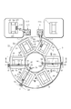
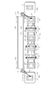
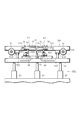
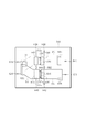
- FIG. 2 is a cross-sectional view taken along the line II-II of the processing apparatus of FIG. It is a top view which shows the table of FIG.
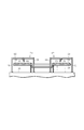
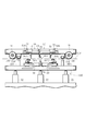
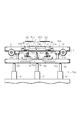
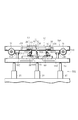
- FIG. 4 is a cross-sectional view of the first positioning station of FIG. 1 as viewed along the line IV-IV. It is sectional drawing explaining the action
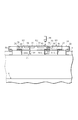
- FIG. 5 is a cross-sectional view taken along the line VI-VI of the first welding processing station in FIG. 1.
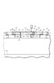
- FIG. 7 is a cross-sectional view taken along the line VII-VII of the cutting processing station of FIG. 1.
- FIG. 8 is a cross-sectional view taken along line VIII-VIII of the second positioning station in FIG. 1.
- FIG. 6 is a cross-sectional view taken along the line IX-IX of the second welding processing station in FIG. 1. It is a top view which shows the table which concerns on another embodiment of this invention. It is a top view which shows the whole welding processing apparatus which concerns on another embodiment of this invention. It is a top view which shows the whole welding processing apparatus which concerns on another embodiment of this invention.
- FIG. 13 is an arrow view of the positioning station of FIG.
- FIG. 14 is an enlarged view of the positioning stopper of FIG. 13. It is a front view explaining the action
- FIG. 12 It is a front view explaining another operation
- the present welding processing apparatus includes a first positioning station 2, a first welding processing station 4, a cutting processing station 6, a second positioning station 8, a second welding processing station 10, A carry-out station 12 is provided, and these six stations 2 to 12 are arranged at equal pitches on the circumference. Above these stations, a turntable 18 supported on a base 14 via a bearing 16 is provided.
- the turntable 18 On the turntable 18, six tables 20 equal to the number of stations described above are arranged at a pitch equal to the pitch.
- the turntable 18 is configured to be rotated along the arrow 22 by one pitch by a driving device (not shown), whereby each table 20 can be stopped at each station in turn.
- the turntable 18 has a donut shape with a hollow center.
- the table 20 is suitable for butt welding of the first blank material B1 and the two second blank materials B2 made of a sheet metal panel as a workpiece, and butt welding of the second blank material B2 and the third blank material B3. Designed. More specifically, as shown in FIG. 3, the table 20 includes a positioning stopper 24 that can contact the butting surface B1a of the first blank material B1 and a butting surface B1a of the first blank material B1.
- the first pressing member 26 that presses the first blank material B1 so as to contact the first blank member B1 and the first blank member B1 are positioned in the width direction, that is, positioned in a direction perpendicular to the pressing direction by the first pressing member 26. It has the guide member 27 and the magnet clamp 28 as a 1st fixing device which fixes 1st blank material B1 to a table.
- the table 20 also presses the second blank material B2 so that the abutting surface B2a of the second blank material B2 contacts the abutting surface B1a of the first blank material B1 fixed to the table 20.
- a magnet clamp 32 as a fixing device.
- the table 20 presses the third blank material B3 so that the abutting surface B3a of the third blank material B3 contacts the abutting surface B2b of the second blank material B2 fixed to the table 20.
- a magnet clamp 36 as a fixing device.
- the positioning stopper 24 protrudes from the upper surface of the table 20 as shown in FIG. 5 and is lowered from the upper surface of the table 20 as shown in FIG. 4 and FIGS. It is supported by a guide 38 provided on the table 20 so that it can move to the rest position.
- the stopper 24 is normally located at the rest position by its own weight or by a spring (not shown) as shown in FIG.
- the first pressing member 26 has an engaging portion 26 ⁇ / b> A that is supported by a guide 40 provided on the table 20 and protrudes below the table 20 so that the first blank member B ⁇ b> 1 on the table 20 can be pressed. ing.
- the second pressing member 30 is supported by the guide 42 so as to be able to press the blank material B2 on the table 20, and has an engaging portion 30A that protrudes downward from the table 20. Further, as shown in FIG. 5, the second pressing member 30 is in a use position protruding on the table 20 and a rest position lowered below the upper surface of the table 20 as shown in FIG. It is supported by a vertical guide 44 supported by a guide 42 so that it can move.
- the pressing member 30 is normally located at the rest position by its own weight or by a spring (not shown).
- the third pressing member 34 is supported by the guide 46 so as to be able to press the blank material B3 on the table 20, and has an engaging portion 30A that protrudes downward from the table 20.
- the first pressing member 26, the second pressing member 30, and the third pressing member 34 are respectively returned to predetermined positions of the guides 40, 42, and 46 by springs (not shown) provided between the tables 20, respectively. It is energized.
- the first, second, and third guide members 27, 31, and 35 are in a use position that contacts the first, second, and third blank members B1, B2, and B3, respectively, and a non-use position that is retracted from the use position. It is movable.
- the guide members 27, 31 and 35 are moved by actuators (not shown) appropriately provided in the first positioning station 2 and the second positioning station 8, similarly to the pressing members 26, 30 and 34.
- the magnet clamps 28, 32, and 36 are respectively provided on the upper surface of the table 20, and the lower surfaces of the first blank material B1, the second blank material B2, and the third blank material B3 are attracted by magnetic force and fixed to the table 20. is there.
- These magnet clamps 28, 32 and 36 include a normal permanent magnet, a magnet whose polarity can be reversed, and an electromagnetic coil for reversing the polarity of the magnet. By energizing the electromagnetic coil, it is possible to switch between a state where a magnetic force is generated on the surface and a state where the magnetic force disappears from the surface.
- the first positioning station 2 the second positioning station 8 and the carry-out station 12
- Each table 20 is fixed at an accurate position on the turntable 18 by positioning pins 50 provided on the turntable 18.
- the first positioning station 2 is provided with a positioning station base 54 that can be moved up and down by a lifting actuator 52.
- the base 54 includes a stopper actuator 56 that pushes the positioning stopper 24 to its use position, a first pressing actuator 58 that drives the first pressing member 26, and a second pressing actuator that drives the second pressing member 30. 60 is provided.
- the stopper actuator 56 when the base 54 is lowered, the stopper actuator 56, the first and second pressing actuators 58 and 60 move the table 20 together with the turntable 18. There is nothing to interfere with.
- the drive portion 56A of the actuator 56 when the base 54 is raised as shown in FIG. 5, by driving the stopper actuator 56, the drive portion 56A of the actuator 56 moves the positioning stopper 24 to its use position. Can do.
- the drive portions 58A and 60A of the actuators 58 and 60 are engaged with the engaging portions 26A and 30A of the pressing members 26 and 30, and can be pressed.
- the actuator 60 causes the upper surface of the drive portion 60A to push up the second pressing member 30 and to protrude onto the table 20 as shown in the figure as the base 54 moves up.
- the first welding processing station 4 is provided with a laser welding device 62.
- the laser welding device 62 includes an outer column 64 provided outside the turntable 18 in the processing station 4, an inner column 66 provided in a hollow portion inside the turntable 18, and the outer column 64 and the inner column 66.
- a rail-shaped guide member 68 bridged between the two, a slider 70 movable along the guide member 68, and a laser head 72 for irradiating a laser supported by the slider 70.
- the laser head 72 is supported by the slider 70 so as to be movable in the vertical direction and so as to be movable in a direction perpendicular to the moving direction of the slider 70.
- the position of the slider 70 relative to the guide member 68 and the position of the laser head 72 relative to the slider 70 are controlled by a controller (not shown) according to the welding position of the blank material.
- a laser cutting device 74 is provided in the cutting processing station 6, .
- the laser cutting device 74 is similar to the laser welding device 62 described above, and is provided in the outer column 76 provided outside the turntable 18 in the cutting processing station 6 and in the hollow portion inside the turntable 18.
- a laser head 84 for irradiating a laser is provided.
- the laser head 84 is supported by the slider 82 so as to be movable in the vertical direction and so as to be movable in a direction perpendicular to the moving direction of the slider 82.
- the position of the slider 82 relative to the guide member 80 and the position of the laser head 84 relative to the slider 82 are controlled by a controller (not shown) according to the cutting position of the blank material.
- the purpose of the cutting process at the cutting station 6 is to correct the butting surface B2b of the second blank B2 welded to the first blank B1 at the first welding station 4. That is, the butt surface B2b of the second blank material B2 welded to the first blank material B1 due to a manufacturing error of the first and second blank materials B1 and B2 or an error generated during welding between the both blank materials B1 and B2.
- an error may occur with respect to the intended design. For this reason, in order to improve the butt
- the laser is irradiated by the laser head 84 at this cutting processing station 6, but no substantial cutting is performed. . That is, cutting can be omitted.
- the second positioning station 8 is provided with a positioning station base 90 that can be moved up and down by a lifting actuator 88.
- the base 90 is provided with a third pressing actuator 92 that drives the third pressing member 34.
- the third pressing actuator 92 does not interfere with the table 20 even if the table 20 moves together with the turntable 18.
- the driving portion 92 ⁇ / b> A of the actuator 92 is engaged with the engaging portion 34 ⁇ / b> A of the pressing member 34 and can be pressed.
- the inner column 66 of the welding device 62, the inner column 78 of the cutting device 74, and the inner column 98 of the welding device 94 can be attached to the base 18. It is.
- a stock yard 110 and a loading robot 112 in which blank materials B1, B2, and B3 before processing are stocked are provided.
- the robot 112 has an adsorbing portion 114 at the tip of the arm, adsorbs the blank materials B1, B2, and B3 on the stock yard 110 and can carry them to a predetermined position on the table 20 located in the positioning station 2. it can.
- a stock yard 116 and an unloading robot 118 are provided in which a finished product C made of blank materials B1, B2, and B3 that has been processed is stocked.
- the robot 118 has a suction part 120 at the tip of the arm, sucks the finished product C on the table 20 located at the carry-out station 12, and carries it to a predetermined position on the table 20 in the stockyard 116 positioning station 2. can do.
- the carrying-in robot 112 sucks the blank materials B1, B2, and B3 in the stock yard 110 and carries them to a predetermined position on the table 20 located in the first positioning station 2.
- the loading position is not required to be so strict, but when positioning the blank materials B1, B2 and B3, the positioning stopper 24, the pressing members 26, 30 and 40, or the guide members 27, 31 and 35 are respectively It is required to be able to contact the blank materials B1, B2, and B3.
- the base 54 is raised by the elevating actuator 52, and then the positioning stopper 24 is moved to the use position protruding from the table 20 by the stopper actuator 46.
- the blank material B1 is pressed by the first pressing member 26 driven by the first pressing actuator 58 so that the butting surface B1A of the first blank material B1 contacts the positioning stopper 24.
- the first guide member 27 driven by an actuator positions the first blank material B1 in the width direction, thereby completing the positioning of the blank material B1.
- the blank material B ⁇ b> 1 is fixed to the table 20 by the magnet clamp 28.
- the positioning stopper 24 is retracted from the upper surface of the table 20 by the actuator 56.
- the blank material B2 is pressed by the second pressing member 30 driven by the second pressing actuator 60 so that the butting surface B2a of the second blank material B2 contacts the butting surface B1a of the first blank material B1.
- the second blank member B2 is positioned in the width direction by the second guide member 31 driven by an actuator (not shown), thereby completing the positioning of the blank material B2.
- the blank material B ⁇ b> 2 is fixed to the table 20 by the magnet clamp 32.
- the turntable 18 is rotated by the one pitch, and the process is executed at the first welding processing station 4.
- the laser is irradiated to the butted surfaces of the first blank material B 1 and the second blank material B 2 fixed to the table 20 by the laser head 72, and both blanks The materials B1 and B2 are welded together.
- a blank assembly is obtained by welding the first blank material B1 and the second blank material B2.
- the turntable 18 is rotated by the one pitch, and the process is executed at the cutting processing station 6.
- the laser head 84 irradiates the laser along the abutting surface B2b of the second blank material B2 welded to the first blank material B1, and the abutting surface B2b It is corrected to the desired shape.
- the turntable 18 is rotated by the one pitch, and the process is executed in the second positioning station 8.
- the base 90 is lifted by the lifting and lowering actuator 88, and then the abutting surface B3a of the third blank material B3 contacts the abutting surface B2b of the second blank material B2.
- the blank material B ⁇ b> 3 is pressed by the third pressing member 34 driven by the third pressing actuator 92.
- the third blank member B3 is positioned in the width direction by the third guide member 35 driven by an actuator (not shown), thereby completing the positioning of the blank material B3.
- the blank material B3 is fixed to the table 20 by the magnet clamp 36.
- a blank assembly is obtained by positioning the blank assembly and the third blank material B3.
- the turntable 18 is rotated by the one pitch, and the process is executed at the second welding processing station 10.
- the laser head 104 irradiates the butted surfaces of the second blank material B2 and the third blank material B3 with each other, and both the blank materials B2 and B3 are mutually connected. Welded. Thereby, the butt welding of blank material B1, B2, and B3 is completed.
- the turntable 18 is rotated by the one pitch, and the process is executed at the carry-out station 12.
- the fixing of the blank materials B1, B2 and B3 by the respective magnet clamps 28, 32 and 36 is released, and the carry-out robot 118 completes the butt welding as shown in FIG.
- the finished product C is adsorbed and moved to the finished product stock yard 116.
- the present welding processing apparatus includes six tables 20 equal to the number of stations, and new blank materials B1, B2, and B3 are sequentially carried into the carry-in station 2 and the carry-out station 12 is loaded. Are sequentially carried out, and the respective processes are executed at the same timing in each of the stations 2, 4, 6, 8, 10 and 12.
- the first blank material B1 and the second blank material B2 are fixed at predetermined positions on the table 20 at the first positioning station 2, and then at the first welding station 4, the first blank material B1 is fixed. And the 2nd blank materials B1 and B2 are welded mutually, and also the butting surface B3a with respect to the 3rd blank material B3 in the 2nd blank material B2 is cut
- FIG. Therefore, regardless of the dimensional error of the first and second blank materials B1 and B2 or the error caused by the butt welding of the first and second blank materials B1 and B2, the second blank material is used in the second positioning station 8.
- a highly accurate butted state between B2 and the third blank material B3 can be obtained. Thereby, in the next second welding station 10, it becomes possible to perform good butt welding between the second blank material B2 and the third blank material B3, and the quality of the welding can also be improved.
- each station 2, 4, 6, 8, 10 and 12 is arranged in order, and the table 20 is arranged at all of these stations.
- the process is executed in parallel at each station, and when the process at each station is completed, all the tables 20 are configured to move to the next station. Therefore, the cycle time for processing the workpiece, that is, the blank material, can be shortened.
- the table 20 from which the finished product is unloaded at the unloading station 12 is configured to be returned to the first positioning station 2 again, each table 20 circulates through each station, and the necessary number of tables Can be minimized.
- each table 20 is arranged on the turntable 18 at a pitch equal to the pitch of each station. After the process at each station is completed, the turntable 18 is rotated by the pitch so that each table 20 becomes the next station. Move to. Thereby, the apparatus for movement of each table 20 can be made very simple including the control.
- a guide member 68, 80, or 104 that supports the laser head 72, 84, or 104 so that the turntable 18 has a donut shape and can be crossed on the table 20 for welding or cutting a blank material, Both ends are supported by outer columns 64, 76 or 96 and inner columns 66, 78 or 98, respectively. Such support at both ends enables the guide member 68, 80, or 104 to be firmly supported, and the laser head 72, 84, or 104 supported so as to be able to move to the guide member 68, 80, or 104 does not fluctuate and follows a desired locus. Can move accurately.
- the guide members 68, 80 or 104 do not interfere with each other.
- the degree of freedom of installation is greatly improved. Supplementing this degree of freedom of installation, if the turntable 18 is not a donut shape and is merely a circle having no hollow portion, the guide member of each welding device or cutting device is traversed across the turntable 18. If provided in this way, sufficient strength can be obtained. However, in that case, there arises a problem that the guide members interfere with each other.
- each table 20 has a positioning stopper 24, pressing members 26, 30 and 34, or guides necessary for positioning the blank materials B1, B2 and B3. Only the members 27, 31 and 35 are provided, and the actuators 56, 58, 60 or 92 etc. for driving them are provided on the base 54 of the first positioning station 2 or the base 90 of the second positioning station 8.
- the actuators 56, 58, 60 or 92 etc. for driving them are provided on the base 54 of the first positioning station 2 or the base 90 of the second positioning station 8.
- the drive portion 56 ⁇ / b> A of the stopper actuator 56 can be engaged with the positioning stopper 24 and lifted by raising the base 54. Further, the driving portion 58A of the pressing actuator 58 can also be engaged with the engaging portion 26A of the first pressing member 26 so as to press the pressing member 26. Further, the driving portion 60A of the stopper actuator 60 is provided with the second pressing member. 30 is projected on the table 20 and engaged with the engaging portion 30A so that the pressing member 30 can be pressed. Conversely, after the process is completed at the first positioning station 2, only the base 54 is lowered, and the engagement between the stopper actuator 56 and the stopper 24 and the pressing actuators 58 and 60 and the pressing members 26 and 30 are performed. Is automatically released. In this way, engagement and release of each actuator can be performed easily.
- the drive portion 92 ⁇ / b> A of the pressing actuator 92 can be engaged with the engaging portion 34 ⁇ / b> A of the third pressing member 34 to press the pressing member 34.
- the engagement between the pressing actuator 90 and the pressing member 34 is automatically released simply by lowering the base 90. In this way, engagement and release of each actuator can be performed easily.
- each blank material B1, B2, and B3 is placed on the table 20 even when the blank materials B1, B2, and B3 are fixed.
- the fixing device for fixing the blank material does not protrude. Therefore, it is possible to prevent such a fixing device from interfering with the welding process and preventing the table 20 from moving.
- the abutting surface B1a of the first blank material B1 is brought into contact with the positioning stopper 24 at the use position to position the first blank material B1.
- the stopper 16 is moved to the rest position, and then the abutting surface B2a of the second blank material B2 is brought into contact with the abutting surface B1a of the first blank material B1 and positioned. Therefore, the butting surfaces B1a and B2a on which the blank materials B1 and B2 are welded can be accurately positioned with respect to the table 20, and the stopper 16 is welded when the butting surfaces B1 and B2 are welded. It can prevent obstruction.
- the butt surface of the second blank B2 welded to the first blank B1 in the first welding station 4 is cut for correction in the next cutting station 6, so that the second and third blanks
- the butting accuracy between the materials B2 and B3 is improved, and thus the welding quality can be improved.
- the first positioning station 2 and the unloading station 12 can be combined into one station to form a total of five stations. .
- the blank materials B1, B2 and B3 are carried onto the table.
- FIG. 10 parts substantially the same as those of the embodiment shown in FIGS. 1 to 9 are denoted by the same reference numerals as those used above, and detailed description thereof is omitted.
- the table 20A adapted to be able to be welded is employed. More specifically, in the table 20 ⁇ / b> A shown in FIG. 10, the L-shaped blank material B ⁇ b> 1 is positioned by the positioning stopper 24, the first pressing member 26 and the guide member 27 and fixed by the first magnet clamp 28.
- the second blank member B2 is positioned with respect to the first blank member B1 by the second pressing member 30 and the guide member 31, and is fixed by the second magnet clamp 32.
- the third blank member B3 is positioned by the third pressing member 34 and the guide member 35 with respect to the first blank member B1 and the second blank member B2 that are welded to each other, and is fixed by the third magnet clamp 36.
- FIG. 10 is different from the embodiment shown in FIGS. 1 to 9 in that the third blank material B3 is also welded to the first blank material B1.
- the embodiment shown in FIG. 10 is the same as the embodiment shown in FIGS.
- a blank assembly consists of 1st blank material B1 and 2nd blank material B2, and welding with this is 1st blank material B1 or 2nd blank material B2, or 1st blank material B1 and 2nd blank material B2. Because it means welding with both.
- the second blank material B2 is welded to the first blank material B1.
- the butting surface B1b of the first blank material B1 with respect to the butting surface B3a of the third blank material B3 is also cut into the desired shape by the cutting device 74.
- the third blank material B3 is positioned with respect to the first and second blank materials B1 and B2.
- the third blank material B3 is welded to the first and second blank materials B1 and B2.
- FIG. 11 shows still another embodiment of the present invention.
- parts that are substantially the same as those of the embodiment shown in FIGS. 1 to 9 or 10 are denoted by the same reference numerals as those used above, and detailed description thereof is omitted.
- the stations 2, 4, 6, 8, 10, and 12 in the embodiment shown in FIG. 1 to FIG. 9 or FIG. 10 are arranged in a straight line.
- a rail 122 that can move each table is provided across each station, and the table 20 ⁇ / b> B moves in the order of these stations 2, 4, 6, 8, 10, and 12. Can do.
- Each table 20B has basically the same structure as the table 20, but wheels (not shown) are provided so as to move on the rail 122.
- a stock yard 100 and a carry-in robot 112 are provided in the vicinity of the first positioning station 2, and a finished product stock yard 116 and a robot 118 are provided in the vicinity of the carry-out station 12.
- a rail 124 is provided from the side of the carry-out station 12 to the side of the first positioning station 2.
- the table 20B which has finished carrying out the finished product at the carry-out station 12 is moved onto the rail 124 on the side of the carry-out station 12 by a conveyor or the like (not shown), and further along the rail 12 to the standby position 126 on the side of the positioning station 2. Moved.
- the table 20B in the standby position is moved again to the first positioning station 2 by a conveyor or the like (not shown).
- a moving device for moving each table 20B to the next station and its control device need to be provided for each table 20B.
- a long rail 124 for returning the table 20B from the carry-out station 12 to the first positioning station 2 and a space for installing the table 20B are required to the side of each station arranged in a straight line.
- the welding processing apparatus of this example includes a positioning station 502, a processing station 504, and a carry-out station 506, and a rail 510 is provided across each station.
- the table 508 to which the blank material is fixed can move through these stations 502, 504 and 506 in order.
- a rail 512 is provided from the side of the carry-out station 506 to the side of the positioning station 502.
- the table 508 that has finished unloading the finished product at the unloading station 506 is moved onto the rail 512 on the side of the unloading station 506 by a conveyor or the like (not shown), and further along the rail 512 to the standby position 514 on the side of the positioning station 502. Moved.
- the table 508 at the standby position is moved again to the carry-in station 502 by a conveyor or the like (not shown).
- Each table 508 is provided with wheels W that roll on rails 510 and 512.
- a total of four tables 508 are provided, and these tables 508 all have the same specifications.
- the table 508 has substantially the same structure as the table 20 described above. Although there are overlapping descriptions below, different parts or clarified parts will be described.
- the table 508 is designed to be suitable for butt welding of the first blank material B1 and the second blank material B2.
- board thickness of 1st blank material B1 is set larger than the plate
- the portion of the first pressing member 26 that contacts the first blank material B1 is configured such that the contact 26C supported via the spring 26B contacts the blank material B1. .
- the portion of the second pressing member 30 that contacts the second blank member B ⁇ b> 2 has an abutment supported by the blank member B ⁇ b> 2 via a spring.
- the first pressing member 26 and the second pressing member 30 are urged so as to return to the initial position by springs 534 and 536 provided between the table 508 and the first pressing member 26 and the second pressing member 30, respectively. Yes.
- a cylindrical engaged member 540 having an opening 538 directed downward is provided on the lower surface of the table 508.
- the base 54 is provided with an engaging member 552 having a truncated cone portion that can be engaged with the opening 538 of the engaged member 540 of the table 508.
- the stopper actuator 56, the first and second pressing actuators 58 and 60, and the engaging member 552 are along the rail 510 of the table 508. There is no part that interferes with movement. Further, in the positioning station 502, when the base 54 is raised as shown in FIG. 15, the truncated cone portion of the engaging member 552 engages with the opening 538 of the engaged member 540, so that the base 54 of the table 508 is not moved. The horizontal position is corrected to the normal position.
- the processing station 506 is provided with a laser welding apparatus 560 as shown in FIG.
- the laser welding apparatus 560 is bridged between two rails 562 extending parallel to the rails 510 on both sides of the processing station 506, two posts 564 respectively guided by the rails 562, and the two posts 564.
- a rail 566 extending perpendicular to the rail 562, a slider 568 guided by the rail 566, and a welding head 570 for irradiating a laser supported by the slider 568.
- the position of the post 564 relative to the rail 562 and the position of the slider 568 relative to the rail 566 are controlled by a controller (not shown) according to the welding position.
- the welding head 570 can move along the butting surfaces of the blank materials B1 and B2, as will be described later.
- the processing station 506 is provided with a processing station base 574 that can be moved up and down by a lifting actuator 572.
- the base 574 can be engaged with the opening 538 of the engaged member 540 of the table 508, and the upward truncated cone portion is positioned below the truncated cone portion and has a larger diameter than the opening 538.
- An engagement member 576 having a large diameter portion is provided. Then, as shown in FIG. 18, by raising the base 574 by the lifting actuator 572, the truncated cone portion of the engaging member 576 is first engaged with the opening 538 of the engaged member of the table 508, The horizontal position of the table 508 with respect to the base 574 is corrected to the normal position. When the base 574 is further lifted by the lifting actuator 572, the large diameter portion of the engaging member 576 comes into contact with the opening 538 of the engaged member 540, and the table 508 can be lifted together with the base 574.
- the operation of the processing apparatus of this example will be described.
- the base 54 is raised by the lifting / lowering actuator 52 at the positioning station 502.
- the engaging member 552 is engaged with the engaged member 538 of the table 508, and the horizontal positioning of the table 508 with respect to the positioning station 502 is performed.
- the wheel W of the table 508 is grounded on the rail 510.
- the positioning stopper 24 is moved to the use position protruding from the table 508 by the stopper actuator 56.
- first blank material B1 is placed on the table 508 between the stopper 24 and the first pressing member 26 on the table 508 and the second blank material B2 is placed on the table 508 by a loading device such as a robot (not shown). Between the stopper 24 and the second pressing member 30.
- the order of placing the blank materials B1 and B2 on the table 508 and the movement of the positioning stopper 24 to the use position may be reversed.
- the blank material is driven by the first pressing member 26 that is driven by the first pressing actuator 58 so that the butting surface B ⁇ b> 1 a of the first blank material B ⁇ b> 1 contacts the positioning stopper 24.
- pressing B1 positioning of the blank material B1 is completed.
- the blank material B 1 is fixed to the table 508 by the magnet clamp 28.
- the positioning stopper 24 is retracted from the upper surface of the table 508 by the actuator 56. Then, the blank material B2 is pressed by the second pressing member 40 driven by the second pressing actuator 60 so that the butting surface B2a of the second blank material B2 contacts the butting surface B1a of the first blank material B1. This completes the positioning of the blank B2.
- the blank B2 is fixed to the table 508 by the magnet clamp 32.
- the base 54 is lowered by the elevating actuator 52 so that the table 508 can be moved from the positioning station 502, and the engagement between the engaging member 552 and the engaged member 540 is released. Is done.
- the table 508 having both the blank materials B1 and B2 fixed on the upper surface is moved to the processing station 504 along the rail 510 by a moving device (not shown).
- the base 574 is raised by the lifting actuator 572, and the engaging member 576 is engaged with the engaged member 538 of the table 508, so that the processing station 504 of the table 508 is engaged.
- Positioning in the horizontal direction is performed.
- the base 574 is further lifted by the lifting actuator 572, the large diameter portion of the engaging member 576 is brought into contact with the edge of the opening 538 of the engaged member 540, and the table 508 is lifted together with the base 574.
- interval of the height direction of the welding materials 570 of the laser welding apparatus 560 and the blank materials B1 and B2 on the table 508 is adjusted.
- the welding head 570 is moved so that the laser is irradiated along the butt surfaces of both blank materials B1 and B2, and the butt surfaces are welded.
- the welding is completed, the adsorption of both blank materials B1 and B2 by the magnet clamps 28 and 32 is released.
- the base 574 is lowered as indicated by a two-dot chain line 574A by the lifting actuator 572 so that the table 508 can be moved from the processing station 504, and is engaged with the engaging member 576.
- the engagement with the member 540 is released.
- the table 508 on which both the blank materials B1 and B2 (hereinafter referred to as finished products) welded to each other are moved to the carry-out station 506 along the rail 510 by a moving device (not shown).
- the finished product is unloaded by a unillustrated unloading device such as a robot.
- the table 508 is returned to the standby position as described above.
- the welding processing apparatus of this example includes four tables 508 and is configured such that each process is executed at the same timing in three stations 502, 504, and 506. . That is, the blank materials B1 and B2 are carried in, positioned and fixed at the positioning station 502, the blank materials B1 and B2 are welded at the processing station 504, and the carry-out is performed at the carry-out station 506.
- each table 508 has a positioning stopper 24 that contacts the first blank material B1, a first pressing member 26 that presses the blank material B1, or a second blank material B2.
- the stopper actuator 56 for moving the positioning stopper 24 and the actuators 58 and 60 for driving the first pressing member 26 and the second pressing member only by providing the second pressing member 32 for pressing the 54. In this way, since it is not necessary to provide these actuators on each table 508, the size of each table 508 can be avoided, and the number of actuators can be kept to a minimum. Cost can be reduced.
- the engaging member 552 provided on the base 54 is engaged with the engaged member 540 of the table 508, so that the positioning of the table 508 is performed reliably, and the pressing actuator 58.
- 60 actuating portions 58A and 60A can be engaged with the engaging portions 26A and 30A of the pressing members 26 and 30, respectively.
- the base 54 is simply lowered, and the engagement between the engaging member 552 and the engaged member 540 of the table 508 is released, and the pressing actuator and the pressing member Can be disengaged.
- the positioning stopper 24 provided on the table 508, the stopper actuator 56 for driving the first pressing member 26 and the second pressing member 32, and the first pressing actuator 58 are provided.
- the second pressing actuator 60 is provided on the elevating base 54 provided in the positioning station 502.
- the actuators 56, 58 and 60 are also provided on the table side.
- parts or portions that are substantially the same as those of the embodiment shown in FIGS. 12 to 18 are denoted by the same reference numerals.
- This embodiment employs a table 590 instead of the table 508 in the above-described embodiment.
- the table 590 on which the blank materials B1 and B2 are placed has basically the same structure as the table 508 of the above-described embodiment. That is, the table 590 includes the positioning stopper 24 that can contact the butting surface B1A of the first blank material B1 and the first blank material B1 so that the butting surface B1A of the first blank material B1 contacts the stopper 24.
- a first pressing member 26 for pressing and a first magnet clamp 28 for fixing the first blank material B1 to the table are provided.
- the table 590 further includes a second pressing member 30 that presses the blank material B2 such that the butting surface B2a of the blank material B2 contacts the butting surface B1a of the first blank material B1 fixed to the table 590, and It has the 2nd magnet clamp 32 which fixes 2nd blank B2 to the table 590.
- a second pressing member 30 that presses the blank material B2 such that the butting surface B2a of the blank material B2 contacts the butting surface B1a of the first blank material B1 fixed to the table 590, and It has the 2nd magnet clamp 32 which fixes 2nd blank B2 to the table 590.
- the table 590 is fixed to a base 592 that can move on the rail 510 by wheels W.
- the base 592 basically has the same structure as the base 54 of the above-described embodiment. That is, the base 592 includes a stopper actuator 56 that pushes the positioning stopper 24 to its use position, a first pressing actuator 58 that drives the first pressing member 26, and a second pressing that drives the second pressing member 30. Actuator 60 is provided.
- the driving portion 56A of the stopper actuator 56 and the positioning stopper 24, the driving portion 58A of the actuator 58 and the engaging portion 26A of the first pressing member 26, and the engaging portion of the driving portion 60A of the actuator 60 and the second pressing member 30. 30A can also be joined in advance.
- the actuators 56, 58 and 60 are provided on the table 590, it is not necessary to provide the base 54 that can be moved up and down at the positioning station 502. However, since the table 590 cannot be moved up and down at the welding station 504, it is preferable that the welding head 570 in the welding apparatus 560 instructs the slider 568 to adjust the vertical position.
- the positioning station 502 first places the butting surface B1a of the first blank material B1 on the positioning stopper 24 in the use position. After the first blank material B1 is fixed, the stopper 24 is moved to its rest position, and then the butt surface B2a of the second blank material B2 is moved to the butt surface B1a of the first blank material B1. Position it in contact with. Therefore, again, the abutting surfaces B1a and B2a to which the blank materials B1 and B2 are welded at the positioning station 502 can be accurately positioned with respect to the table 590 and the welding station 504 welds the abutting surfaces B1 and B2. In this case, it is possible to prevent the stopper 24 from interfering with welding.
- the table according to this embodiment is a third blank material having a basic shape corresponding to a mirror image of the first blank material and a second blank instead of the first blank material and the second blank material in each of the above-described embodiments.
- the fourth blank material having a basic shape corresponding to a mirror image of the material is abutted against each other, and the both blank materials are adapted to be welded to each other at the abutting surface.
- the table 600 includes a positioning stopper 616 that can abut on the abutting surface C1a of the first blank material C1 and an abutting surface C1a of the first blank material C1 that abuts on the stopper 616.
- the 1st press member 620 which presses the 1st blank material C1
- the two 1st magnet clans 622 which fix the 1st blank material C1 to a table.
- the table 600 further includes a second pressing member 624 that presses the blank material C2 such that the abutting surface C2a of the second blank material C2 contacts the abutting surface C1a of the first blank material C1 fixed to the table 600.
- the first and second magnet clamps 622 and 624 are driven by an actuator (not shown), as in the embodiment shown in FIG. 12 to FIG. 18 or FIG.
- the table 600 is provided with a guide member 680 for positioning the first blank material C1 in the width direction and a guide member 682 for positioning the second blank material C2 in the width direction.
- These guide members 680 and 682 can be moved by a not-shown actuator to a use position where they abut against the first and second blank materials C1 and C2, respectively, and to a non-use position retracted from the use position.
- the table 600 further matches a third blank material C3 having a basic shape corresponding to a mirror image of the first blank material C1 and a fourth blank material C4 having a basic shape corresponding to a mirror image of the second blank material C2. It is adapted so that it can be used. That is, the table 600 fixes the third blank material C3 and the pressing member 628 that presses the third blank material C3 so that the butting surface C3A of the third blank material C3 contacts the positioning stopper 616. It has a magnet clamp 630 for blank material.
- the table 600 includes a pressing member 632 that presses the fourth blank material C4 and a fourth blank material C4 so that the abutting surface C4A of the fourth blank material C4 contacts the abutting surface C3a of the third blank material C3.
- a magnet clamp 634 for the fourth blank material to be fixed is provided.
- the third blank C3 is fixed to the table by one of the first magnet clamps 622 and the magnet clamp 630
- the fourth blank C4 is fixed to the table by one of the second magnet clamps 626 and the magnet clamp 634.
- the guide members 680 and 682 are also used for positioning in the width direction of the third and fourth blank materials C3 and C4, respectively.
- the table 600 can be used for positioning and fixing not only the first and second blank materials C1 and C2, but also the third and fourth blank materials C3 and C4. There is no need to prepare a table dedicated to the fourth blank material. This saves the trouble of exchanging the table of the welding processing apparatus and can also reduce the cost.
- the positioning stopper 616 and the guide members 680 and 682 are also used for positioning the third and fourth blank materials C3 and C4, and one of the first magnet clamp 622 and the second magnet clamp.
- One of 626 is also used for fixing the third and fourth blanks. For this reason, the number of magnet clamps added for positioning and fixing the third and fourth blank materials C3 and C4 can be reduced.
- the basic shape corresponding to the above-described mirror image does not mean that all parts are strictly symmetric.
- a panel constituting a side part of a car body of an automobile may be partially different even if the basic shape is the same because of the parts or design to be attached on the left side and the right side. Therefore, it is clear that this embodiment can be applied even in such a case.
- board thickness differs is often abutted, and in that case, the panel after welding has a front and back. For this reason, it is necessary to perform welding by positioning and fixing the blank materials C3 and C4 on the table 600 in a mirror image shape.
- the table 700 includes a positioning stopper 616 with which the butting surface D1a of the first blank material D1 abuts, a first pressing member 620 that presses the first blank material D1, and a first blank material D1.
- Two second magnet clamps 626 and guide members 680 and 682 for positioning the first and second blank materials D1 and D2 in the width direction, respectively.
- the table 700 is provided with a third blank material so that the third and fourth blank materials D3 and D4 having basic shapes corresponding to mirror images of the first and second blank materials D1 and D2, respectively, can be positioned and fixed.
- the positioning stopper 636 that contacts the butting surface D3a of D3, the pressing member 638 that presses the third blank material D3, the magnet clamp 640 that fixes the third blank material D3, and the butting surface D4a of the fourth blank material D4 are the third.
- a pressing portion 642 that presses against the butting surface D3a of the blank material D3, a magnet clamp 644 that fixes the fourth blank material D4, and a guide that positions the third and fourth blank materials D3 and D4 in the width direction, respectively.
- Members 646 and 648 are provided.
- the guide members 680 and 682 located on the center side of the table 700 also move from the illustrated position toward the upper side of the drawing so that the third and fourth blank materials D3 and D4 can be positioned in the width direction, respectively. It is configured as follows.
- Second positioning station 10 Second welding processing station 12 Unloading station 18 Turntable 20, 20A, 20B Table 24 Positioning stopper 26, 30, 34 Pressing member 28 , 32, 36 Magnet clamp 56 Actuator for stopper 58, 60, 92 Actuator for pressing 62, 94 Welding device 72 Cutting device 502 Positioning station 504 Processing station 508 Table 540 Engagement member 560 Welding device 570 Welding head B1, C1, D1 1st blank material B2, C2, D2 2nd blank material C3, D3 3rd blank material C4, D4 4th blank material
Landscapes
- Physics & Mathematics (AREA)
- Optics & Photonics (AREA)
- Engineering & Computer Science (AREA)
- Mechanical Engineering (AREA)
- Plasma & Fusion (AREA)
- Robotics (AREA)
- Laser Beam Processing (AREA)
- Automatic Assembly (AREA)
Abstract
Priority Applications (4)
| Application Number | Priority Date | Filing Date | Title |
|---|---|---|---|
| RU2011129642/02A RU2481934C2 (ru) | 2008-12-16 | 2009-12-14 | Сварочная установка и способ сварки |
| US13/139,139 US20110240612A1 (en) | 2008-12-16 | 2009-12-14 | Welding apparatus and welding method |
| CN2009801563453A CN102307702A (zh) | 2008-12-16 | 2009-12-14 | 焊接加工装置及使用其的焊接加工方法 |
| EP09833412A EP2377642A4 (fr) | 2008-12-16 | 2009-12-14 | Appareil de soudage et procédé de soudage utilisant l'appareil |
Applications Claiming Priority (6)
| Application Number | Priority Date | Filing Date | Title |
|---|---|---|---|
| JP2008-319460 | 2008-12-16 | ||
| JP2008319460A JP5196169B2 (ja) | 2008-12-16 | 2008-12-16 | ワークの加工装置 |
| JP2008-319461 | 2008-12-16 | ||
| JP2008319461A JP5196170B2 (ja) | 2008-12-16 | 2008-12-16 | 溶接加工装置及び溶接加工方法 |
| JP2008-322503 | 2008-12-18 | ||
| JP2008322503A JP5196173B2 (ja) | 2008-12-18 | 2008-12-18 | 溶接加工装置 |
Publications (1)
| Publication Number | Publication Date |
|---|---|
| WO2010071109A1 true WO2010071109A1 (fr) | 2010-06-24 |
Family
ID=42268779
Family Applications (1)
| Application Number | Title | Priority Date | Filing Date |
|---|---|---|---|
| PCT/JP2009/070834 Ceased WO2010071109A1 (fr) | 2008-12-16 | 2009-12-14 | Appareil de soudage et procédé de soudage utilisant l'appareil |
Country Status (6)
| Country | Link |
|---|---|
| US (1) | US20110240612A1 (fr) |
| EP (1) | EP2377642A4 (fr) |
| KR (1) | KR20110084327A (fr) |
| CN (1) | CN102307702A (fr) |
| RU (1) | RU2481934C2 (fr) |
| WO (1) | WO2010071109A1 (fr) |
Cited By (8)
| Publication number | Priority date | Publication date | Assignee | Title |
|---|---|---|---|---|
| CN104669800A (zh) * | 2014-06-10 | 2015-06-03 | 滁州品之达电器科技有限公司 | 改进型激光标记系统 |
| CN106585117A (zh) * | 2014-06-10 | 2017-04-26 | 赵牧青 | 具有出料机械手的经济型激光标印系统 |
| CN108857186A (zh) * | 2018-08-22 | 2018-11-23 | 常州机电职业技术学院 | 机器人焊接工作站及其旋转式多工位变位机 |
| CN111185669A (zh) * | 2020-03-05 | 2020-05-22 | 浙江嘉泰激光科技股份有限公司 | 一种钣金箱体激光焊接机 |
| CN116237619A (zh) * | 2023-03-28 | 2023-06-09 | 威海邦德散热系统股份有限公司 | 一种汽车热交换器自动焊接工作站及焊接工艺 |
| CN118768840A (zh) * | 2024-08-12 | 2024-10-15 | 保定市天乾电气科技有限公司 | 一种电力铁附件焊接对接装置 |
| DE102023111811A1 (de) * | 2023-05-05 | 2024-11-07 | Baosteel Lasertechnik Gmbh | Laservorrichtung und Verfahren, insbesondere zur Herstellung eines ringförmig, geschlossenen Bauteils |
| CN119747974A (zh) * | 2024-11-29 | 2025-04-04 | 中钰匠鑫机械制造有限公司 | 一种三工位多角度智能焊接系统及其焊接方法 |
Families Citing this family (36)
| Publication number | Priority date | Publication date | Assignee | Title |
|---|---|---|---|---|
| CN102896444B (zh) * | 2012-06-13 | 2015-07-01 | 江南大学 | 自动叠片机 |
| MX353892B (es) * | 2012-09-25 | 2018-02-01 | Keylex Corp | Aparato para soldadura. |
| US9937579B2 (en) | 2013-07-16 | 2018-04-10 | Hobart Brothers Company | Integrated cable management for welding and cutting systems |
| US9527154B2 (en) * | 2013-07-16 | 2016-12-27 | Hobart Brothers Company | Integrated cable management for welding and cutting systems |
| WO2015072934A1 (fr) * | 2013-11-13 | 2015-05-21 | Tamer Akçay Ve Ortaklari Bilişim Sistemleri Kollektif Şirketi | Machine laser comprenant quatre tables coulissantes et procédé de chargement d'un produit |
| CN106079906A (zh) * | 2014-06-10 | 2016-11-09 | 赵牧青 | 一种改进型激光标印系统 |
| CN104028895B (zh) * | 2014-06-10 | 2016-06-15 | 滁州品之达电器科技有限公司 | 一种激光标印系统 |
| CN104029499A (zh) * | 2014-06-10 | 2014-09-10 | 滁州品之达电器科技有限公司 | 一种激光标印装置 |
| CN105904853A (zh) * | 2014-06-10 | 2016-08-31 | 赵牧青 | 一种具有补料机构的激光标印系统 |
| CN105882153A (zh) * | 2014-06-10 | 2016-08-24 | 赵牧青 | 经济型激光标印系统 |
| CN104139271B (zh) * | 2014-08-12 | 2016-04-27 | 安徽江淮汽车股份有限公司 | 焊接夹具及焊装生产线 |
| DE102014112888A1 (de) * | 2014-09-08 | 2016-03-10 | Wisco Lasertechnik Gmbh | Laser-Ablations- und Schweißverfahren für Werkstücke |
| CN107405733B (zh) * | 2015-03-20 | 2019-11-26 | 本田技研工业株式会社 | 板材对接装置 |
| DE102015115463A1 (de) * | 2015-09-14 | 2017-03-16 | Wilco Wilken Lasertechnik GmbH | Vorrichtung und Verfahren zur Bearbeitung von Werkstücken |
| CA2998569C (fr) * | 2015-09-18 | 2022-02-15 | Honda Motor Co., Ltd. | Procede de traitement au laser et dispositif de traitement au laser |
| CN105081551A (zh) * | 2015-09-29 | 2015-11-25 | 梧州恒声电子科技有限公司 | 一种超声波焊接倒相管夹具 |
| JP6829542B2 (ja) * | 2015-12-02 | 2021-02-10 | Kyb株式会社 | ワーク移送装置 |
| JP6643880B2 (ja) * | 2015-12-02 | 2020-02-12 | Kyb株式会社 | ワーク把持装置 |
| CN106001914A (zh) * | 2016-07-19 | 2016-10-12 | 苏州誉衡昌精密机械有限公司 | 一种激光焊接机构 |
| JP6772371B2 (ja) * | 2016-09-26 | 2020-10-21 | トルンプ ヴェルクツォイクマシーネ ゲーエムベーハー+シーオー.ケージー | 特に板金である板状工作物の加工のための方法および工具機械 |
| US10105797B1 (en) * | 2017-06-22 | 2018-10-23 | Btd Manufacturing, Inc. | Welding table |
| EP3479951A1 (fr) * | 2017-11-07 | 2019-05-08 | Weil Engineering GmbH | Machine de traitement de matière ainsi que procédé de fabrication d'un récipient dans une machine de traitement de matière |
| EP4420821A3 (fr) * | 2017-11-29 | 2025-01-01 | Magna International Inc. | Ensemble de fixation et procédé pour opérations de soudage |
| IT201800003770A1 (it) * | 2018-03-20 | 2019-09-20 | Mecc Pi Erre S R L Di Pederzoli Ruggero & C | Impianto per l’esecuzione di operazioni di realizzazione di un pezzo a partire da un getto |
| CN110293358B (zh) * | 2019-07-09 | 2021-07-09 | 深圳市亿和精密科技集团有限公司 | 一种焊接用转盘机构的控制方法 |
| DE102019213685B4 (de) * | 2019-09-10 | 2021-04-01 | Trumpf Laser- Und Systemtechnik Gmbh | Verfahren zum Positionieren eines Bearbeitungskopfes einer Laserbearbeitungsanlage sowie zugehörige Laserbearbeitungsanlage und Computerprogrammprodukt |
| ES3056353T3 (en) * | 2019-11-05 | 2026-02-19 | Magna Int Inc | Fixture assembly for supporting blanks during shearing and welding operations |
| JP7222945B2 (ja) * | 2020-03-12 | 2023-02-15 | 株式会社アイシン | 回転電機用ステータ製造方法 |
| CN112453675A (zh) * | 2020-10-16 | 2021-03-09 | 安徽佩吉智能科技有限公司 | 一种半自动化铝焊机 |
| US20240189950A1 (en) * | 2021-04-09 | 2024-06-13 | Magna International Inc. | System for welding multiple blanks into a component |
| CN113245736B (zh) * | 2021-05-31 | 2022-07-12 | 岳西县顺达机械有限公司 | 一种新能源汽车配件自动化加工设备 |
| CN218016641U (zh) * | 2022-03-30 | 2022-12-13 | 无锡先导智能装备股份有限公司 | 焊接装置 |
| CN115647825B (zh) * | 2022-12-05 | 2023-03-28 | 浙江求是半导体设备有限公司 | 一种焊带载体、焊带载体组件、焊接设备以及焊接方法 |
| TWI851012B (zh) * | 2023-02-08 | 2024-08-01 | 儀辰企業股份有限公司 | 夾爪定位的永磁式電控磁盤 |
| CN116765704A (zh) * | 2023-06-30 | 2023-09-19 | 武汉海尔热水器有限公司 | 内胆对接焊接设备 |
| CN117733448A (zh) * | 2023-12-01 | 2024-03-22 | 北京博尔顿智能装备技术研究院有限公司 | 一种折弯机机架点焊定位装置及方法 |
Citations (6)
| Publication number | Priority date | Publication date | Assignee | Title |
|---|---|---|---|---|
| JPS57199576A (en) * | 1981-06-03 | 1982-12-07 | Nippon Kokan Kk <Nkk> | Producing installation for liner plate |
| JPH0560683U (ja) * | 1992-01-29 | 1993-08-10 | マツダ株式会社 | 溶接用治具台車の被溶接物支持位置変更装置 |
| JPH08290282A (ja) | 1995-04-21 | 1996-11-05 | Sanyo Mach Works Ltd | レーザ溶接装置 |
| JPH09248636A (ja) * | 1996-03-18 | 1997-09-22 | Amada Co Ltd | 板材加工機 |
| JPH11198004A (ja) * | 1998-01-14 | 1999-07-27 | Ckd Corp | ワークの加工方法及び加工装置 |
| JP2004001081A (ja) * | 2002-03-27 | 2004-01-08 | Sumikin Plant Ltd | 金属板の突き合わせ溶接方法及び装置 |
Family Cites Families (7)
| Publication number | Priority date | Publication date | Assignee | Title |
|---|---|---|---|---|
| US3745319A (en) * | 1971-08-25 | 1973-07-10 | M Unigovsky | Apparatus for resistance butt welding of several pipes into extended sections |
| SU716760A1 (ru) * | 1977-08-24 | 1980-02-25 | Всесоюзный Научно-Исследовательский Институт По Монтажным И Специальным Строительным Работам | Поточна лини дл изготовлени металлических конструкций |
| SU753573A1 (ru) * | 1978-01-09 | 1980-08-07 | Проектно-Конструкторский Технологический Экспериментальный Институт Машиностроения | Поточна лини дл сборки и сварки блоков цилиндров дизельных двигателей |
| DE3344805A1 (de) * | 1983-12-12 | 1985-06-13 | Expert Maschinenbau Gmbh, 6143 Lorsch | Hub-drehtisch-vorrichtung |
| US5630269A (en) * | 1995-06-19 | 1997-05-20 | General Motors Corporation | Method for fixturing abutted sheet metal parts for welding |
| US6031199A (en) * | 1997-10-28 | 2000-02-29 | Worthington Machine Technology | Combination laser cutting and blank welding apparatus and method |
| RU2208506C2 (ru) * | 2001-02-21 | 2003-07-20 | Федеральное государственное унитарное предприятие центральный научно-исследовательский институт технологии судостроения | Автоматизированный участок резки и сварки металлических конструкций |
-
2009
- 2009-12-14 CN CN2009801563453A patent/CN102307702A/zh active Pending
- 2009-12-14 WO PCT/JP2009/070834 patent/WO2010071109A1/fr not_active Ceased
- 2009-12-14 US US13/139,139 patent/US20110240612A1/en not_active Abandoned
- 2009-12-14 EP EP09833412A patent/EP2377642A4/fr not_active Withdrawn
- 2009-12-14 RU RU2011129642/02A patent/RU2481934C2/ru not_active IP Right Cessation
- 2009-12-14 KR KR1020117013660A patent/KR20110084327A/ko not_active Abandoned
Patent Citations (6)
| Publication number | Priority date | Publication date | Assignee | Title |
|---|---|---|---|---|
| JPS57199576A (en) * | 1981-06-03 | 1982-12-07 | Nippon Kokan Kk <Nkk> | Producing installation for liner plate |
| JPH0560683U (ja) * | 1992-01-29 | 1993-08-10 | マツダ株式会社 | 溶接用治具台車の被溶接物支持位置変更装置 |
| JPH08290282A (ja) | 1995-04-21 | 1996-11-05 | Sanyo Mach Works Ltd | レーザ溶接装置 |
| JPH09248636A (ja) * | 1996-03-18 | 1997-09-22 | Amada Co Ltd | 板材加工機 |
| JPH11198004A (ja) * | 1998-01-14 | 1999-07-27 | Ckd Corp | ワークの加工方法及び加工装置 |
| JP2004001081A (ja) * | 2002-03-27 | 2004-01-08 | Sumikin Plant Ltd | 金属板の突き合わせ溶接方法及び装置 |
Non-Patent Citations (1)
| Title |
|---|
| See also references of EP2377642A4 |
Cited By (10)
| Publication number | Priority date | Publication date | Assignee | Title |
|---|---|---|---|---|
| CN104669800A (zh) * | 2014-06-10 | 2015-06-03 | 滁州品之达电器科技有限公司 | 改进型激光标记系统 |
| CN106427228A (zh) * | 2014-06-10 | 2017-02-22 | 赵牧青 | 具有夹具的激光标记系统 |
| CN106585117A (zh) * | 2014-06-10 | 2017-04-26 | 赵牧青 | 具有出料机械手的经济型激光标印系统 |
| CN108857186A (zh) * | 2018-08-22 | 2018-11-23 | 常州机电职业技术学院 | 机器人焊接工作站及其旋转式多工位变位机 |
| CN111185669A (zh) * | 2020-03-05 | 2020-05-22 | 浙江嘉泰激光科技股份有限公司 | 一种钣金箱体激光焊接机 |
| CN111185669B (zh) * | 2020-03-05 | 2022-03-11 | 浙江嘉泰激光科技股份有限公司 | 一种钣金箱体激光焊接机 |
| CN116237619A (zh) * | 2023-03-28 | 2023-06-09 | 威海邦德散热系统股份有限公司 | 一种汽车热交换器自动焊接工作站及焊接工艺 |
| DE102023111811A1 (de) * | 2023-05-05 | 2024-11-07 | Baosteel Lasertechnik Gmbh | Laservorrichtung und Verfahren, insbesondere zur Herstellung eines ringförmig, geschlossenen Bauteils |
| CN118768840A (zh) * | 2024-08-12 | 2024-10-15 | 保定市天乾电气科技有限公司 | 一种电力铁附件焊接对接装置 |
| CN119747974A (zh) * | 2024-11-29 | 2025-04-04 | 中钰匠鑫机械制造有限公司 | 一种三工位多角度智能焊接系统及其焊接方法 |
Also Published As
| Publication number | Publication date |
|---|---|
| US20110240612A1 (en) | 2011-10-06 |
| CN102307702A (zh) | 2012-01-04 |
| RU2481934C2 (ru) | 2013-05-20 |
| EP2377642A1 (fr) | 2011-10-19 |
| EP2377642A4 (fr) | 2012-12-05 |
| RU2011129642A (ru) | 2013-01-27 |
| KR20110084327A (ko) | 2011-07-21 |
Similar Documents
| Publication | Publication Date | Title |
|---|---|---|
| WO2010071109A1 (fr) | Appareil de soudage et procédé de soudage utilisant l'appareil | |
| JP5196169B2 (ja) | ワークの加工装置 | |
| KR101221591B1 (ko) | 테일러 웰디드 블랭크 용접 시스템 | |
| JP5196170B2 (ja) | 溶接加工装置及び溶接加工方法 | |
| KR102156830B1 (ko) | 스테이터 코어용 레이저 용접장치 및 이를 이용한 레이저 용접방법 | |
| US6912774B2 (en) | Apparatus and method for assembly of motorcycle frame | |
| US20080105733A1 (en) | System and Method For Assembling Motor-Vehicle Body Structures or Sub Assemblies Thereof | |
| JP5212632B2 (ja) | 溶接加工装置 | |
| JP5077576B2 (ja) | 加工装置 | |
| JP3558988B2 (ja) | 溶接方法及び溶接システム | |
| KR200375423Y1 (ko) | 테일러 웰디드 블랭크 용접시스템 | |
| JP5196173B2 (ja) | 溶接加工装置 | |
| JP2007118033A (ja) | レーザ溶接方法とレーザ溶接装置 | |
| JP4506632B2 (ja) | 突合せ溶接方法およびその装置 | |
| JP3810701B2 (ja) | レーザー溶接装置及びその溶接方法 | |
| JP5207731B2 (ja) | ワーク突合わせ装置 | |
| JP2006239764A (ja) | 車両用ドアインパクトビームの製造方法及びその製造装置。 | |
| JP4799806B2 (ja) | ワーク突合わせ装置 | |
| KR101654353B1 (ko) | 레이저 삭마장치 | |
| JP4458013B2 (ja) | ワーク位置決め方法および装置 | |
| JP2011101934A (ja) | 樹脂製ワーク用加工装置及び樹脂製加工品の製造方法 | |
| JPWO2013118438A1 (ja) | 加工システム、ワーク加工方法及び制御方法 | |
| CN117921234A (zh) | 箱体焊接系统 |
Legal Events
| Date | Code | Title | Description |
|---|---|---|---|
| WWE | Wipo information: entry into national phase |
Ref document number: 200980156345.3 Country of ref document: CN |
|
| 121 | Ep: the epo has been informed by wipo that ep was designated in this application |
Ref document number: 09833412 Country of ref document: EP Kind code of ref document: A1 |
|
| WWE | Wipo information: entry into national phase |
Ref document number: 13139139 Country of ref document: US |
|
| WWE | Wipo information: entry into national phase |
Ref document number: 2009833412 Country of ref document: EP |
|
| ENP | Entry into the national phase |
Ref document number: 20117013660 Country of ref document: KR Kind code of ref document: A |
|
| NENP | Non-entry into the national phase |
Ref country code: DE |
|
| WWE | Wipo information: entry into national phase |
Ref document number: 4590/DELNP/2011 Country of ref document: IN |
|
| WWE | Wipo information: entry into national phase |
Ref document number: 2011129642 Country of ref document: RU |