WO2010071134A1 - Procédé de fabrication de matériau photo-durcissable, matériau photodurcissable et article - Google Patents
Procédé de fabrication de matériau photo-durcissable, matériau photodurcissable et article Download PDFInfo
- Publication number
- WO2010071134A1 WO2010071134A1 PCT/JP2009/070917 JP2009070917W WO2010071134A1 WO 2010071134 A1 WO2010071134 A1 WO 2010071134A1 JP 2009070917 W JP2009070917 W JP 2009070917W WO 2010071134 A1 WO2010071134 A1 WO 2010071134A1
- Authority
- WO
- WIPO (PCT)
- Prior art keywords
- compound
- fine particles
- photocurable material
- polymerizable component
- meth
- Prior art date
- Legal status (The legal status is an assumption and is not a legal conclusion. Google has not performed a legal analysis and makes no representation as to the accuracy of the status listed.)
- Ceased
Links
Images

Classifications
-
- C—CHEMISTRY; METALLURGY
- C08—ORGANIC MACROMOLECULAR COMPOUNDS; THEIR PREPARATION OR CHEMICAL WORKING-UP; COMPOSITIONS BASED THEREON
- C08L—COMPOSITIONS OF MACROMOLECULAR COMPOUNDS
- C08L33/00—Compositions of homopolymers or copolymers of compounds having one or more unsaturated aliphatic radicals, each having only one carbon-to-carbon double bond, and only one being terminated by only one carboxyl radical, or of salts, anhydrides, esters, amides, imides or nitriles thereof; Compositions of derivatives of such polymers
- C08L33/04—Homopolymers or copolymers of esters
-
- C—CHEMISTRY; METALLURGY
- C08—ORGANIC MACROMOLECULAR COMPOUNDS; THEIR PREPARATION OR CHEMICAL WORKING-UP; COMPOSITIONS BASED THEREON
- C08F—MACROMOLECULAR COMPOUNDS OBTAINED BY REACTIONS ONLY INVOLVING CARBON-TO-CARBON UNSATURATED BONDS
- C08F2/00—Processes of polymerisation
- C08F2/44—Polymerisation in the presence of compounding ingredients, e.g. plasticisers, dyestuffs, fillers
-
- C—CHEMISTRY; METALLURGY
- C08—ORGANIC MACROMOLECULAR COMPOUNDS; THEIR PREPARATION OR CHEMICAL WORKING-UP; COMPOSITIONS BASED THEREON
- C08F—MACROMOLECULAR COMPOUNDS OBTAINED BY REACTIONS ONLY INVOLVING CARBON-TO-CARBON UNSATURATED BONDS
- C08F292/00—Macromolecular compounds obtained by polymerising monomers on to inorganic materials
-
- C—CHEMISTRY; METALLURGY
- C08—ORGANIC MACROMOLECULAR COMPOUNDS; THEIR PREPARATION OR CHEMICAL WORKING-UP; COMPOSITIONS BASED THEREON
- C08K—Use of inorganic or non-macromolecular organic substances as compounding ingredients
- C08K3/00—Use of inorganic substances as compounding ingredients
- C08K3/18—Oxygen-containing compounds, e.g. metal carbonyls
- C08K3/20—Oxides; Hydroxides
- C08K3/22—Oxides; Hydroxides of metals
-
- C—CHEMISTRY; METALLURGY
- C08—ORGANIC MACROMOLECULAR COMPOUNDS; THEIR PREPARATION OR CHEMICAL WORKING-UP; COMPOSITIONS BASED THEREON
- C08K—Use of inorganic or non-macromolecular organic substances as compounding ingredients
- C08K9/00—Use of pretreated ingredients
- C08K9/04—Ingredients treated with organic substances
-
- G—PHYSICS
- G02—OPTICS
- G02B—OPTICAL ELEMENTS, SYSTEMS OR APPARATUS
- G02B1/00—Optical elements characterised by the material of which they are made; Optical coatings for optical elements
- G02B1/04—Optical elements characterised by the material of which they are made; Optical coatings for optical elements made of organic materials, e.g. plastics
-
- Y—GENERAL TAGGING OF NEW TECHNOLOGICAL DEVELOPMENTS; GENERAL TAGGING OF CROSS-SECTIONAL TECHNOLOGIES SPANNING OVER SEVERAL SECTIONS OF THE IPC; TECHNICAL SUBJECTS COVERED BY FORMER USPC CROSS-REFERENCE ART COLLECTIONS [XRACs] AND DIGESTS
- Y10—TECHNICAL SUBJECTS COVERED BY FORMER USPC
- Y10S—TECHNICAL SUBJECTS COVERED BY FORMER USPC CROSS-REFERENCE ART COLLECTIONS [XRACs] AND DIGESTS
- Y10S977/00—Nanotechnology
- Y10S977/70—Nanostructure
- Y10S977/773—Nanoparticle, i.e. structure having three dimensions of 100 nm or less
-
- Y—GENERAL TAGGING OF NEW TECHNOLOGICAL DEVELOPMENTS; GENERAL TAGGING OF CROSS-SECTIONAL TECHNOLOGIES SPANNING OVER SEVERAL SECTIONS OF THE IPC; TECHNICAL SUBJECTS COVERED BY FORMER USPC CROSS-REFERENCE ART COLLECTIONS [XRACs] AND DIGESTS
- Y10—TECHNICAL SUBJECTS COVERED BY FORMER USPC
- Y10S—TECHNICAL SUBJECTS COVERED BY FORMER USPC CROSS-REFERENCE ART COLLECTIONS [XRACs] AND DIGESTS
- Y10S977/00—Nanotechnology
- Y10S977/70—Nanostructure
- Y10S977/778—Nanostructure within specified host or matrix material, e.g. nanocomposite films
-
- Y—GENERAL TAGGING OF NEW TECHNOLOGICAL DEVELOPMENTS; GENERAL TAGGING OF CROSS-SECTIONAL TECHNOLOGIES SPANNING OVER SEVERAL SECTIONS OF THE IPC; TECHNICAL SUBJECTS COVERED BY FORMER USPC CROSS-REFERENCE ART COLLECTIONS [XRACs] AND DIGESTS
- Y10—TECHNICAL SUBJECTS COVERED BY FORMER USPC
- Y10T—TECHNICAL SUBJECTS COVERED BY FORMER US CLASSIFICATION
- Y10T428/00—Stock material or miscellaneous articles
- Y10T428/29—Coated or structually defined flake, particle, cell, strand, strand portion, rod, filament, macroscopic fiber or mass thereof
- Y10T428/2982—Particulate matter [e.g., sphere, flake, etc.]
- Y10T428/2991—Coated
- Y10T428/2993—Silicic or refractory material containing [e.g., tungsten oxide, glass, cement, etc.]
- Y10T428/2995—Silane, siloxane or silicone coating
-
- Y—GENERAL TAGGING OF NEW TECHNOLOGICAL DEVELOPMENTS; GENERAL TAGGING OF CROSS-SECTIONAL TECHNOLOGIES SPANNING OVER SEVERAL SECTIONS OF THE IPC; TECHNICAL SUBJECTS COVERED BY FORMER USPC CROSS-REFERENCE ART COLLECTIONS [XRACs] AND DIGESTS
- Y10—TECHNICAL SUBJECTS COVERED BY FORMER USPC
- Y10T—TECHNICAL SUBJECTS COVERED BY FORMER US CLASSIFICATION
- Y10T428/00—Stock material or miscellaneous articles
- Y10T428/31504—Composite [nonstructural laminate]
- Y10T428/31678—Of metal
-
- Y—GENERAL TAGGING OF NEW TECHNOLOGICAL DEVELOPMENTS; GENERAL TAGGING OF CROSS-SECTIONAL TECHNOLOGIES SPANNING OVER SEVERAL SECTIONS OF THE IPC; TECHNICAL SUBJECTS COVERED BY FORMER USPC CROSS-REFERENCE ART COLLECTIONS [XRACs] AND DIGESTS
- Y10—TECHNICAL SUBJECTS COVERED BY FORMER USPC
- Y10T—TECHNICAL SUBJECTS COVERED BY FORMER US CLASSIFICATION
- Y10T428/00—Stock material or miscellaneous articles
- Y10T428/31504—Composite [nonstructural laminate]
- Y10T428/31855—Of addition polymer from unsaturated monomers
Definitions
- the present invention relates to a method for producing a photocurable material, a photocurable material obtained by the production method, and an article obtained using the photocurable material.
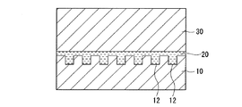
- a mold having a reverse pattern of the fine pattern on its surface is pressed against a photocurable material arranged on the surface of the substrate.
- a method photo nanoimprint method in which light is applied to the photocurable material, the photocurable material is cured, and a fine pattern is formed on the surface of a substrate (see Patent Documents 1 and 2). ).
- the refractive index may be required to be 1.54 or more. Therefore, a high refractive index may be required for a cured product of the photocurable material.
- As means for increasing the refractive index it has been studied to disperse inorganic fine particles having a refractive index higher than that of an organic material in a photocurable material.
- Patent Document 3 As a method for dispersing the inorganic fine particles in the photocurable material, a method is known in which the surface of the inorganic fine particles is modified with a compound having a high affinity with the photocurable material (Patent Document 3).
- Patent Document 3 a method in which the surface of the inorganic fine particles is modified with a compound having a high affinity with the photocurable material.
- the inorganic fine particles obtained by this method have good dispersibility in the photocurable material before curing, they are extruded along with crosslinking when the photocurable material is cured, and the extruded inorganic fine particles are precipitated or agglomerated. As a result, the transparency of the cured product is impaired.
- Patent Document 4 As a method for maintaining the dispersion of the inorganic fine particles even when the photocurable material is cured, there is a method in which the inorganic fine particles modified with a compound having a high affinity are further modified with a compound having the same reactive site as the photocurable material.
- Patent Document 4 Since the inorganic fine particles modified by this method have the same reaction point as the photocurable material, they are fixed in the cured product in a dispersed state when the photocurable material is cured. However, in this method, the compound that modifies the inorganic fine particles becomes bulky, resulting in problems that the refractive index as designed cannot be obtained and the refractive index is lowered.
- Non-Patent Document 1 a method of modifying inorganic fine particles with acrylic acid has been proposed. Since the molecular weight of acrylic acid is small, the compound that modifies the inorganic fine particles is not bulky and looks like a good method at first glance. However, since acrylic acid alone cannot sufficiently cover the polarity of the surface of the inorganic fine particles, the inorganic fine particles modified with acrylic acid have a relatively high polarity. Therefore, the following problems arise.
- the inorganic fine particles are usually provided as an aqueous sol, it is necessary to extract from the aqueous sol with an organic solvent before adding the inorganic fine particles modified with acrylic acid to the photocurable material.
- organic solvent such as methanol
- inorganic fine particles modified with acrylic acid can be dispersed only in an organic solvent (such as methanol) having a relatively high polarity. Therefore, before extraction, filtration, solvent substitution, etc. are needed, and a process increases.
- the photocurable material to be dispersed is also limited to those having relatively high polarity (such as non-fluorinated (meth) acrylates).
- the photocurable material When dispersing inorganic fine particles in a photocurable material containing highly hydrophobic fluoro (meth) acrylates, fluorine-based surfactants, etc., the photocurable material while suppressing the bulk of the compound that modifies the inorganic fine particles as much as possible. It is necessary to impart affinity to the inorganic fine particles and to introduce reaction points with the photocurable material. However, as described above, in the conventional method, the bulk of the compound that modifies the inorganic fine particles is suppressed as much as possible, the affinity to the photocurable material is imparted to the inorganic fine particles, and the reaction point with the photocurable material is set. Is also difficult to introduce.
- the present invention provides a photocurable material capable of forming a cured product having a high refractive index and a high transparency, a method capable of easily producing the material, and an article having a high refractive index and a high transparency.
- the method for producing a photocurable material of the present invention includes the following steps (i) to (iii). (I) reacting a polymerizable component (A) comprising at least one compound (a) having a (meth) acryloyloxy group with a compound (B) having a mercapto group and a carboxy group, to thereby react the compound (B) A step of obtaining a surface modifying agent (C) having a carboxy group derived from the terminal. (Ii) A step of obtaining the surface modified inorganic fine particles (E) by modifying the surface of the inorganic fine particles (D) with the surface modifier (C).
- the number of moles of the polymerizable component (A) in the step (i) is preferably 0.5 to 10 times the number of moles of the compound (B).
- the mass of the inorganic fine particles (D) in the step (ii) is preferably 0.2 to 10 times the mass of the compound (B) used in the step (i).
- the total of the polymerizable component (A), the compound (B), the inorganic fine particles (D), the polymerizable component (F), and the photopolymerization initiator (G) can be obtained by displaying the raw material charge ratio ( 100% by mass), the total of the polymerizable component (A) and the polymerizable component (F) is 10 to 98.8% by mass, and the compound (B) is 0.01 to 28% by mass.
- the inorganic fine particles (D) are 0.1 to 75% by mass
- the photopolymerization initiator (G) is 0.1 to 9% by mass.
- the pKa of the compound (B) is preferably 4.4 or less.
- the compound (B) preferably satisfies the following conditions (1) to (3).
- Condition (1) having one or more mercapto groups.
- Condition (2) having one or more carboxy groups.
- Condition (3) No primary amino group.
- the compound (B) is an aliphatic carboxylic acid having 2 to 20 carbon atoms and has a mercapto group at least in any of the ⁇ -position, ⁇ -position and ⁇ -position of the carboxyl group, and does not have a primary amino group. A compound is preferred.
- the molecular weight of the compound (B) is preferably 600 or less.
- the inorganic fine particles (D) are preferably metal oxide fine particles.
- the metal oxide is titanium oxide, zirconium oxide, aluminum oxide, barium titanate, cerium oxide, tin oxide, zinc oxide, tantalum oxide, manganese oxide, nickel oxide, iron oxide, silicon oxide, niobium oxide, lanthanum oxide and oxidation. It is preferably at least one selected from the group consisting of gadolinium.
- the average primary particle diameter of the inorganic fine particles (D) is preferably 2 to 100 nm.
- the polymerizable component (F) preferably contains a compound (f2) having a fluorine atom and having one or more (meth) acryloyloxy groups.
- the polymerizable component (F) is a compound (f1) having two or more (meth) acryloyloxy groups (excluding the compound (f2)), a fluorine atom, and a (meth) acryloyloxy group.
- the compound (f2) and the compound (f3) having one (meth) acryloyloxy group (excluding the compound (f2)), wherein the compound (f1), the compound (f2) and the compound Of the total (100% by mass) of the compound (f3), the compound (f1) is 15 to 70% by mass, the compound (f2) is 5 to 45% by mass, and the compound (f3) is It is preferably 10 to 65% by mass.
- the polymerizable component (A) is preferably composed of one or more of the compounds (f) constituting the polymerizable component (F). It is preferable that the polymerizable component (A) is the same polymerizable component as the polymerizable component (F).
- the photocurable material of the present invention is obtained by the production method of the present invention.
- the photocurable material of the present invention preferably contains substantially no solvent.
- the article of the present invention is a product obtained by curing the photocurable material of the present invention, or has a cured film formed by curing the photocurable material of the present invention on the surface of a substrate.
- a photocurable material capable of forming a cured product having a high transparency and a high refractive index can be easily produced.
- the photocurable material of the present invention can form a cured product having high transparency and high transparency.
- the article of the present invention has high transparency and refractive index.
- a compound represented by the formula (f21) is referred to as a compound (f21).
- a (meth) acryloyloxy group means an acryloyloxy group or a methacryloyloxy group.
- (meth) acrylate means an acrylate or a methacrylate.
- the method for producing a photocurable material of the present invention is a method having the following steps (i) to (iii).
- a polymerizable component (A) composed of one or more compounds (a) having a (meth) acryloyloxy group is reacted with a compound (B) having a mercapto group and a carboxy group to give the compound (B)
- Photocuring comprising surface-modified inorganic fine particles (E), a polymerizable component (F) composed of one or more compounds (f) having a (meth) acryloyloxy group, and a photopolymerization initiator (G).
- E surface-modified inorganic fine particles
- F polymerizable component
- G photopolymerization initiator
- Step (i) is a step of reacting the polymerizable component (A) with the compound (B) to obtain a surface modifier (C) having a carboxy group derived from the compound (B) at the terminal.
- the polymerizable component (A) is a polymerizable component composed of one or more compounds (a).
- the compound (a) is a compound having a (meth) acryloyloxy group, and examples thereof include those exemplified as the compound (f) described later.
- the polymerizable component (A) from the viewpoint of dispersibility of the surface-modified inorganic fine particles (E) in the polymerizable component (F), one of the compounds (f) constituting the polymerizable component (F) described later is used.
- a polymerizable component comprising at least species is preferable, and the same polymerizable component as the polymerizable component (F) is more preferable.
- the same polymerizable component means that the types and ratios of the compounds are the same.
- the compound (B) is a compound having a mercapto group and a carboxy group.
- the mercapto group reacts with the carbon-carbon unsaturated double bond of the (meth) acryloyloxy group of the polymerizable component (A).
- the high affinity of the carboxy group derived from the compound (B) capable of binding to the inorganic fine particles (D) and the polymerizable component (F) and the polymerizable property serving as a reaction point between the polymerizable component (F).
- a surface modifier (C) having a structure derived from the component (A) is obtained.
- it is an unreacted mercapto group in the step (i), it becomes a reaction point with the polymerizable component (F).
- the mercapto group may be protected by a protecting group.
- the protecting group may be removed and then reacted with the polymerizable component (A), or may be reacted with the polymerizable component (A) under deprotection conditions.
- the protecting group include known protecting groups such as a trityl group, a benzyl group, and a disulfide bond.
- the number of carboxy groups in the compound (B) may be one or plural. In the case of a plurality, it is preferably 2.
- the compound (B) preferably has a pKa of 4.4 or less.
- the surface modification inorganic fine particles (E) are obtained by modifying the inorganic fine particles (D) using the surface modifier (C) having a carboxy group derived from the compound (B) at the terminal. At this time, it is preferable that the carboxy group of the surface modifier (C) is sufficiently dissociated.
- the carboxy group of the surface modifier (C) is sufficiently dissociated and the modification of the inorganic fine particles (D) proceeds smoothly.
- the lower limit value of the pKa of the compound (B) is not particularly limited, but for reasons such as the type of compounds that are usually available and the durability of the cured product of the photocurable material obtained by the present invention, ⁇ 2 is preferred and 0 is particularly preferred. Therefore, the pKa range of the compound (B) is preferably ⁇ 2 to 4.4, and particularly preferably 0 to 4.3.
- the pKa of the compound (B) in the present invention is a value calculated from the measured value by measuring the pH of the aqueous solution of the compound (B) at 20 ° C.
- Condition (1) having one or more mercapto groups.
- Condition (2) having one or more carboxy groups.
- Condition (3) No primary amino group.
- the carboxy group derived from the compound (B) is bonded to the surface of the inorganic fine particles (D). If the carboxy group is sufficiently dissociated, it is easy to bond to the surface of the inorganic fine particles (D). Therefore, the compound (B) may have a substituent so as to adjust the acidity of the carboxy group.
- the type, number and substitution position of the substituent in the compound (B) are as follows.
- the carboxy group in the compound (B) (and thus the carboxy group in the surface modifier (C)) is inorganic fine particles (as a whole). What is necessary is just to adjust so that it may have the acidity which can couple
- N-acylamino group such as N-acetylamino group, secondary amino group, tertiary amino group, quaternary ammonium group, imino group, halogen atom, alkoxy group, hydroxyl group, formyl group, keto group, carboxy group, acid chloride Ester group, amide group, cyano group, nitroso group, nitro group, alkenyl group, alkynyl group, aryl group, phenyl group, cycloalkyl group, heterocyclic group, thioether group, mercapto group, sulfonyl group, Fmoc (9-full (Oleenylmethyloxycarbonyl) group and the like.
- N-acylamino group such as N-acetylamino group, secondary amino group, tertiary amino group, quaternary ammonium group, imino group, halogen atom, alkoxy group, hydroxyl group, formyl group, keto group, carb
- halogen atoms, keto groups, carboxy groups, cyano groups, nitro groups and the like which are generally understood to have electron-withdrawing properties, are preferred, but other substituents and N-acylamino groups
- the carboxyl group of the compound (B) generally has an electron-donating property within a range in which the carboxyl group of the compound (B) can take an appropriate dissociation state for the modification of the inorganic fine particles (D), depending on the combination and the substitution position of Groups can also be combined as appropriate.
- the substituent is a mercapto group
- the mercapto group may satisfy the condition (1) at the same time.
- the compound (B) does not have a primary amino group.
- the inorganic fine particles (D) are likely to aggregate in the step (ii). Moreover, it reacts with a carboxy group over time and causes coloring.
- the compound (B) is an aliphatic carboxylic acid having 2 to 20 carbon atoms, having a mercapto group at least in any of the ⁇ -position, ⁇ -position and ⁇ -position of the carboxyl group, and having a primary amino group.
- the compound is not.
- the “carbon number” is a number including carbon atoms in the carboxyl group (—COOH).
- the site structure of the aliphatic carboxylic acid excluding the carboxyl group may be a linear structure or a branched structure.
- the unsaturated bond may be included.
- the site is preferably a linear or branched aliphatic saturated hydrocarbon group.
- the aliphatic carboxylic acid may have a substituent as described above.
- a cysteine derivative in which an amino group is substituted with an acyl group is also preferable.
- the molecular weight of the compound (B) is preferably 600 or less, and more preferably 400 or less. When the molecular weight exceeds 600, the affinity for the polymerizable component (A), the polymerizable component (F) and the organic solvent increases due to the long-chain alkyl group, etc., but the molecule becomes bulky. ) And the optical properties of the polymerizable component (F) and the optical properties of the inorganic fine particles (D) do not produce the results as designed, or may decrease from the target refractive index. .
- Examples of the compound (B) include the following compounds.
- the molecular weight in parentheses for each compound is the molecular weight.
- the mercapto group of the compound may be protected with a protective group, the compounds may be disulfide bonded, or may further have a substituent.
- the surface modifier (C) is obtained by reacting the polymerizable component (A) with the compound (B). This reaction is a reaction between the carbon-carbon unsaturated double bond of the (meth) acryloyloxy group of the polymerizable component (A) and the mercapto group of the compound (B), that is, an ene-thiol reaction.
- the reason for reacting the polymerizable component (A) and the compound (B) is as follows.
- the compound (B) is reacted with the polymerizable component (A) of the same type as the polymerizable component (F) in which the inorganic fine particles (D) are dispersed so as to approach the ideal state.
- a carboxy group capable of binding to the inorganic fine particles (D) is introduced.
- the structure derived from the polymerizable component (A) having high affinity with the polymerizable component (F) is converted into the structure of the third component other than the polymerizable component (A) and the inorganic fine particles (D). It can be introduced on the surface of the inorganic fine particles (D) with the existence reduced as much as possible.
- This reaction is performed, for example, by dissolving the compound (B) in an organic solvent, adding a polymerizable component (A) and a photopolymerization initiator to the compound, and irradiating with light.
- the reaction does not have to be performed completely, and unreacted substances may remain.
- the compound (B) may react with the terminal of a polymer obtained by polymerizing a part of the polymerizable component (A).
- the number of moles of the polymerizable component (A) is preferably 0.5 to 10 times, more preferably 0.9 to 5 times the number of moles of the compound (B).
- the number of moles of the polymerizable component (A) is less than 0.5 times the number of moles of the compound (B)
- the unreacted compound (B) that is, the polymerizable component (A) and the surface modifier (C)
- Surface modifiers that have insufficient affinity with the polymerizable component (F) will increase, and the inorganic fine particles (D) will easily aggregate in step (ii).
- the number of moles of the polymerizable component (A) exceeds 10 times the number of moles of the compound (B)
- the number of carboxy groups in the surface modifier (C) becomes relatively small. D) cannot be extracted sufficiently.
- the organic solvent is not particularly limited as long as it can dissolve the polymerizable component (A), the compound (B) and the photopolymerization initiator and does not react with them, and is preferably an organic solvent having low solubility in water.
- the compound (B) is preferably dissolved in the organic solvent in the range of 10 to 200 mg / mL.
- the addition amount of the photopolymerization initiator is preferably 0.1 to 5 parts by mass with respect to 100 parts by mass in total of the polymerizable component (A) and the compound (B).
- the kind of light should just be selected suitably according to a photoinitiator, for example, the ultraviolet-ray which has a dominant wavelength in 365 nm is mentioned.
- the light irradiation time is, for example, 1 minute to 3 hours for an irradiation density of 10 mW.
- the reaction in step (i) may be performed in two or more stages.
- Step (ii) is a step of obtaining the surface-modified inorganic fine particles (E) by modifying the surface of the inorganic fine particles (D) with the surface modifier (C).
- metal oxide fine particles are preferable.
- the metal oxide include oxides of at least one metal selected from the group consisting of metals belonging to Group 4 of the periodic table, metals belonging to Group 13 of the periodic table, and metals belonging to Group 14 of the periodic table.
- metals belonging to Group 4 of the periodic table include Ti, Zr, and Hf.
- the metal belonging to Group 13 of the periodic table include Al, Ga, and In.
- metals belonging to Group 14 of the periodic table include Si, Ge, Sn, and Pb.
- Metal oxides include titanium oxide, zirconium oxide, aluminum oxide, barium titanate, cerium oxide, tin oxide, zinc oxide, tantalum oxide, manganese oxide, nickel oxide, iron oxide, silicon oxide, niobium oxide, lanthanum oxide, oxidation Gadolinium is preferred.
- the average primary particle diameter of the inorganic fine particles (D) is preferably 2 nm to 100 nm, more preferably 4 nm to 60 nm. If the average primary particle diameter is 100 nm or less, the transparency of the cured product in the visible light region can be maintained. When the average primary particle diameter is 2 nm or more, an increase in the necessary amount of the compound (B) accompanying the enlargement of the total specific surface area of the fine particles can be avoided.
- the average primary particle diameter of the inorganic fine particles (D) is measured by a dynamic scattering method in a dispersion state.
- the inorganic fine particles (D) may be used alone or in combination of two or more, or may be fine particles of a composite metal oxide composed of two or more.
- Examples of the form of the inorganic fine particles (D) include a powder, a dispersion (sol) dispersed in a solvent (dispersion medium), and the dispersion is preferable from the viewpoint of the transparency of the cured product.
- An aqueous dispersion that is water is more preferred.
- the concentration of the inorganic fine particles (D) in the aqueous dispersion is preferably 1 to 35% by mass, more preferably 2 to 20% by mass. If the concentration is too thin, the extraction efficiency of the surface-modified inorganic fine particles (E) from the aqueous dispersion is deteriorated. When the concentration is too high, the inorganic fine particles (D) are aggregated in the aqueous dispersion due to mechanical stress applied when the surface-modified inorganic fine particles (E) are extracted from the aqueous dispersion.
- the surface-modified inorganic fine particles (E) are obtained by modifying the surface of the inorganic fine particles (D) with the surface modifier (C).
- the modification is performed, for example, by mixing a solution obtained by dissolving the surface modifier (C) in an organic solvent having low solubility in water and an aqueous sol of inorganic fine particles (D), and then modifying the surface modified inorganic fine particles (E) into the organic solvent. Is done by extracting.
- the mass of the inorganic fine particles (D) is preferably 0.2 to 10 times, more preferably 0.67 to 10 times the mass of the compound (B) used in the step (i).
- the mass of the inorganic fine particles (D) exceeds 10 times the mass of the compound (B) used in the step (i)
- the inorganic fine particles (D) cannot be sufficiently extracted, and the inorganic fine particles that have not been extracted ( D) will aggregate.
- the surplus surface modifier (C) has a surface active action, so that the surface modifier (C)
- the solution and the aqueous dispersion medium of the inorganic fine particles (D) are emulsified.
- the aqueous solvent is removed by a known method such as decantation or a separatory funnel to obtain an extract of the surface-modified inorganic fine particles (E).
- the extract contains water
- the water dissolved in the extract can be further removed by adding a highly hydrophobic organic solvent such as hexane to the extract.
- the extract is concentrated by a known method such as distillation under reduced pressure before the step (iii) described later or is substantially free of solvent.
- a known method such as distillation under reduced pressure before the step (iii) described later or is substantially free of solvent.
- the reason is as follows. Since a structure derived from the polymerizable component (A) having a high affinity with the polymerizable component (F) is introduced on the surface of the inorganic fine particles (D), a solvent having a somewhat lower affinity remains as much as possible.
- the extract of the surface-modified inorganic fine particles (E) is temporarily stored or when the polymerizable component (F) is mixed in the step (iii), the phase separation or the surface-modified inorganic fine particles (E) Aggregation can be suppressed.
- a small amount of alcohol such as methanol or ethanol during the distillation under reduced pressure because water azeotropes.
- Step (iii) is a step of obtaining a photocurable material containing the surface-modified inorganic fine particles (E), the polymerizable component (F), and the photopolymerization initiator (G).
- the polymerizable component (F) is a polymerizable component comprising at least one compound (f) having a (meth) acryloyloxy group.
- a compound (f) may be used individually by 1 type, and may use 2 or more types together.
- As the polymerizable component (F), three types of combinations of the compound (f1), the compound (f2), and the compound (f3) are preferable from the viewpoint of releasability, mechanical strength, and transparency of the cured product.
- Compound (f1) is a compound having two or more (meth) acryloyloxy groups (excluding compound (f2)).
- the number of (meth) acryloyloxy groups in the compound (f1) is preferably from 2 to 10, particularly preferably from 2 to 6.
- Examples of the compound (f1) include (meth) acrylates of bisphenols, (meth) acrylates having a fluorene skeleton, (meth) acrylates having a naphthalene skeleton, (meth) acrylates of diols such as glycols, glycerol and trimethylol Examples include (meth) acrylates of triols and (meth) acrylates of tetraols such as pentaerythritol, (meth) acrylates of diols, (meth) acrylates of triols, and (meth) acrylates of tetraols are preferred.
- Examples of the compound (f1) include the following compounds.
- a monomer having a urethane bond or a monomer containing a silicon atom such as 1,3-bis (3-methacryloyloxypropyl) -1,1,3,3-tetramethyldisiloxane can also be employed.
- Compound (f1) may be used alone or in combination of two or more.
- the ratio of the compound (f1) is 15 to 70% by mass, preferably 25 to 60% by mass, out of the total (100% by mass) of the compound (f1), the compound (f2) and the compound (f3).
- the amount of the compound (f1) is 15% by mass or more, the cured product has good mechanical strength. If the amount of the compound (f1) is 70% by mass or less, the cured product will not undergo phase separation.
- the compound (f2) is a compound having a fluorine atom and having at least one (meth) acryloyloxy group.
- Examples of the compound (f2) include fluoro (meth) acrylates. Fluoro (meth) acrylates are preferable in terms of compatibility.
- Fluoro (meth) acrylates are preferably compound (f21) from the viewpoints of compatibility and environmental characteristics.
- R 1 is a hydrogen atom or a methyl group
- R 2 and R 3 are each a hydrogen atom or an alkyl group having 1 to 4 carbon atoms
- R 4 and R 5 are a fluorine atom and a carbon number, respectively.
- Is a perfluoroalkyl group having 1 to 4 carbon atoms or a perfluoroalkoxy group having 1 to 4 carbon atoms
- R 6 is a hydrogen atom or a fluorine atom
- m is an integer of 1 to 4
- n is It is an integer from 1 to 16.
- n is preferably an integer of 1 to 10 from the viewpoint of compatibility, and more preferably an integer of 3 to 6 from the viewpoint of environmental characteristics.
- the amount of the compound (f2) is 5 to 45% by mass, preferably 15 to 35% by mass, of the total (100% by mass) of the compound (f1), the compound (f2) and the compound (f3).
- the amount of the compound (f2) is 5% by mass or more, a cured product having excellent releasability can be obtained, and foaming of the photocurable material can be suppressed. Since the foaming of the photocurable material can be suppressed, it is easy to filter during preparation, and further, defects in the pattern shape due to mixing of bubbles can be eliminated during nanoimprinting. If the amount of the compound (f2) is 45% by mass or less, a cured product having excellent mechanical strength can be obtained because it can be uniformly mixed.
- the compound (f3) is a compound having one (meth) acryloyloxy group (excluding the compound (f2)).
- the compound (f3) is a component that dissolves other components and is a component that improves the compatibility between the compound (f1) and the compound (f2). If the compatibility between the compound (f1) and the compound (f2) is good, the foaming during the preparation of the photocurable material is suppressed, and the photocurable material can be easily prepared, for example, through a filter. Can be obtained. Furthermore, by obtaining a homogeneous cured product, it is possible to sufficiently exhibit mold releasability and mechanical strength.
- an organic group having 1 to 30 carbon atoms is preferably bonded to the oxygen atom of the ester structure (COO—).
- the carbon number of the organic group is particularly preferably 4 to 20, and particularly preferably 4 to 12.
- Examples of the organic group include a linear alkyl group, a branched alkyl group, a cycloalkyl group, an alkyl group substituted with an aryl group, an allyl group, a bridged hydrocarbon group, a group having a repeating structure of an oxyalkylene chain, and an aromatic group And heterocyclic groups.
- These groups may be substituted with a heteroatom such as a nitrogen atom or an oxygen atom or a silicon atom, or may be substituted with a functional group such as a hydroxyl group or an amino group, and an unsaturated bond or a free carboxyl group may be substituted. You may have. Among these, a linear alkyl group, a branched alkyl group, a cycloalkyl group, and a bridged hydrocarbon group are preferable among these. Examples of the compound (f3) include the following compounds.
- the amount of the compound (f3) is 10 to 65% by mass, preferably 15 to 50% by mass, out of the total (100% by mass) of the compound (f1), the compound (f2) and the compound (f3).
- the amount of the compound (f3) is 10% by mass or more, the compatibility between the compound (f1) and the compound (f2) is good.
- the amount of the compound (f3) is 65% by mass or less, the sensitivity becomes a value of 1000 mJ / cm 2 or less, and the photocurable material exhibits good sensitivity.
- Photopolymerization initiator (G) examples include acetophenone photopolymerization initiator, benzoin photopolymerization initiator, benzophenone photopolymerization initiator, thioxanthone photopolymerization initiator, ⁇ -aminoketone photopolymerization initiator, ⁇ -hydroxy Ketone-based photopolymerization initiator, ⁇ -acyl oxime ester, benzyl- (o-ethoxycarbonyl) - ⁇ -monooxime, acylphosphine oxide, glyoxy ester, 3-ketocoumarin, 2-ethylanthraquinone, camphorquinone, tetramethylthiuram
- examples thereof include sulfide, azobisisobutyronitrile, benzoyl peroxide, dialkyl peroxide, tert-butyl peroxypivalate, and the like.
- acetophenone photopolymerization initiator benzoin photopolymerization initiator, ⁇ -Aminoketone photopolymerization
- An initiator or a benzophenone photopolymerization initiator is preferred.
- acetophenone photopolymerization initiator examples include the following compounds. Acetophenone, p- (tert-butyl) 1 ′, 1 ′, 1′-trichloroacetophenone, chloroacetophenone, 2 ′, 2′-diethoxyacetophenone, hydroxyacetophenone, 2,2-dimethoxy-2′-phenylacetophenone, 2 -Aminoacetophenone, dialkylaminoacetophenone, etc.
- benzoin photopolymerization initiator examples include the following compounds. Benzyl, benzoin, benzoin methyl ether, benzoin ethyl ether, benzoin isopropyl ether, benzoin isobutyl ether, 1-hydroxycyclohexyl phenyl ketone, 2-hydroxy-2-methyl-1-phenyl-2-methylpropan-1-one, 1- (4-Isopropylphenyl) -2-hydroxy-2-methylpropan-1-one, benzyldimethyl ketal and the like.
- Examples of the ⁇ -aminoketone photopolymerization initiator include the following compounds. 2-benzyl-2-dimethylamino-1- (4-morpholinophenyl) -butanone-1, 2-methyl-1 [4- (methylthio) phenyl] -2-morpholinopropan-1-one and the like.
- benzophenone-based photopolymerization initiator examples include the following compounds. Benzophenone, benzoylbenzoic acid, methyl benzoylbenzoate, methyl-o-benzoylbenzoate, 4-phenylbenzophenone, hydroxybenzophenone, hydroxypropylbenzophenone, acrylic benzophenone, 4,4′-bis (dimethylamino) benzophenone, etc.
- a photoinitiator (G) may be used individually by 1 type, and may use 2 or more types together.
- the photocurable material may contain an additive (H) excluding the surface-modified inorganic fine particles (E), the polymerizable component (F), and the photopolymerization initiator (G).
- additive (H) include surfactants, photosensitizers, other resins, carbon compounds, metal fine particles, and other organic compounds.
- a fluorine-containing surfactant is preferable. When the fluorine-containing surfactant is used, the effect of improving the releasability of the cured product is also exhibited.
- a fluorine-containing surfactant having a fluorine content of 10 to 70% by mass is preferable, and a fluorine-containing surfactant having a fluorine content of 10 to 40% by mass is more preferable.
- the fluorine-containing surfactant may be water-soluble or fat-soluble, and is preferably fat-soluble from the viewpoint of compatibility in the photocurable material and dispersibility in the cured product.
- an anionic fluorine-containing surfactant As the fluorine-containing surfactant, an anionic fluorine-containing surfactant, a cationic fluorine-containing surfactant, an amphoteric fluorine-containing surfactant, or a nonionic fluorine-containing surfactant is preferable, and compatibility in a photocurable material, From the viewpoint of dispersibility in the cured product, a nonionic fluorine-containing surfactant is more preferable.
- anionic fluorine-containing surfactant a polyfluoroalkyl carboxylate, a polyfluoroalkyl phosphate, or a polyfluoroalkyl sulfonate is preferable.
- Specific examples of the anionic fluorine-containing surfactant include Surflon S-111 (trade name, manufactured by AGC Seimi Chemical Co., Ltd.), Fluorad FC-143 (trade name, manufactured by Sumitomo 3M), and Megafuck F-120 (trade name). DIC, etc.).
- a trimethylammonium salt of polyfluoroalkylcarboxylic acid or a trimethylammonium salt of polyfluoroalkylsulfonic acid amide is preferable.
- Specific examples of the cationic fluorine-containing surfactant include Surflon S-121 (trade name, manufactured by AGC Seimi Chemical Co., Ltd.), Florard FC-134 (trade name, manufactured by Sumitomo 3M Limited), and Megafuck F-150 (trade name). DIC, etc.).
- amphoteric fluorine-containing surfactant polyfluoroalkyl betaine is preferable.
- amphoteric fluorine-containing surfactant include Surflon S-132 (trade name, manufactured by AGC Seimi Chemical Co., Ltd.), Florard FX-172 (trade name, manufactured by Sumitomo 3M), MegaFuck F-120 (trade name, DIC) and the like.
- nonionic fluorine-containing surfactant polyfluoroalkylamine oxide or polyfluoroalkyl / alkylene oxide adduct is preferable.
- specific examples of the nonionic fluorine-containing surfactant include Surflon S-145 (trade name, manufactured by AGC Seimi Chemical Co., Ltd.), Surflon S-393 (trade name, manufactured by AGC Seimi Chemical Co., Ltd.), and Surflon KH-20 (trade name).
- examples thereof include amine compounds such as tetramine and 4,4′-bis (dialkylamino) benzophenone.
- Examples of other resins include polystyrene, polythiophene, polyester oligomer, polycarbonate, poly (meth) acrylate, and the like.
- Examples of the carbon compound include carbon nanotubes and fullerenes.
- Examples of the metal fine particles include copper and platinum.
- Examples of other organic compounds include porphyrin and metal-encapsulated polyphyllin.
- the total amount of the additive (H) is preferably 10% by mass or less in the photocurable material (100% by mass). If the total amount of the additive (H) is 10% by mass or less, it can be uniformly mixed with the photocurable material, and a homogeneous photocurable material can be obtained.
- the timing of adding the additive (H) may be any of steps (i) to (iii) or after step (iii), and is preferably after step (iii).
- the photocurable material is prepared, for example, by adding the polymerizable component (F) to the surface-modified inorganic fine particles (E), stirring well, then adding the photopolymerization initiator (G), and stirring well.
- the surface-modified inorganic fine particles (E) may be in the state of an extract, may be in a state in which the extract is concentrated, or may be in a state that does not substantially contain a solvent.
- the photocurable material is substantially removed from the solvent by a known method such as distillation under reduced pressure. Do not include.
- step (i) the polymerizable component (A) is changed into the surface modifier (C) together with the compound (B). Therefore, in the photocurable material, the idea of minimizing the amount of the surface modifier (C) used, and the surface modifier (C) is no longer the polymerizable component (A) or the polymerizable component (F). Since it does not have an equivalent photocuring property, the step (iii) is performed from the viewpoint of imparting the photocuring property.
- the mass ratio of the polymerizable component (F) to the mass of the polymerizable component (A) in the step (i) is the inorganic fine particles (D) of the photocurable material to be finally obtained. ) Varies depending on the content.
- the mass ratio of the polymerizable component (F) to the mass of the polymerizable component (A) in the step (i) is large.
- the amount of the polymerizable component (F) relative to the mass of the polymerizable component (A) in the step (i) becomes smaller.
- the mass ratio (A / F) is preferably 0.01 to 100, more preferably 0.1 to 10.
- the photocurable material obtained is substantially only the surface-modified inorganic fine particles (E). Therefore, a polymerizable component designed as a photocurable material.
- the curability, viscosity and the like of (A) and the polymerizable component (F) are greatly different in the end, or the handleability of the photocurable material is impaired due to thixotropy.
- the mass ratio (A / F) is more than 100, that is, in step (ii), an attempt is made to extract the inorganic fine particles (D) with a very small amount of the surface modifier (C).
- the manufacturing method does not work well.
- the ratio of each raw material in the steps (i) to (iii) is as follows.
- the total ratio of the polymerizable component (A) and the polymerizable component (F) is as follows: the polymerizable component (A), the compound (B), the inorganic fine particles (D), the polymerizable component (F), and the photopolymerization initiator (G ) Is preferably 10 to 98.8% by mass, more preferably 15 to 98% by mass. If the total ratio of the polymerizable component (A) and the polymerizable component (F) is 10% by mass or more, the photocurable material has sufficient photocurability. When the total ratio of the polymerizable component (A) and the polymerizable component (F) is 98.8% by mass or less, the respective raw materials are easily mixed uniformly.
- the ratio of the compound (B) is the total of the polymerizable component (A), the compound (B), the inorganic fine particles (D), the polymerizable component (F) and the photopolymerization initiator (G) (100% by mass). 0.01 to 28% by mass is preferable, and 0.1 to 15% by mass is more preferable. If the ratio of a compound (B) is 0.01 mass% or more, dispersion
- the proportion of the inorganic fine particles (D) is the total (100% by mass) of the polymerizable component (A), the compound (B), the inorganic fine particles (D), the polymerizable component (F) and the photopolymerization initiator (G). 0.1 to 75% by mass is preferable, and 2 to 57% by mass is more preferable. When the proportion of the inorganic fine particles (D) is 0.1% by mass or more, the effect of modifying physical properties by forming a composite material with the inorganic fine particles (D) appears. When the proportion of the inorganic fine particles (D) is 75% by mass or less, the inorganic fine particles (D) can be dispersed without agglomeration.
- a photoinitiator (G) Content of a photoinitiator (G) is 0. of the sum total (100 mass%) of a polymeric component (A), a compound (B), a polymeric component (F), and a photoinitiator (G). 1 to 9% by mass is preferable, and 0.5 to 6% by mass is more preferable. If the ratio of a photoinitiator (G) is 0.1 mass% or more, a hardened
- step (i) the polymerizable component (A) and compound (B) are reacted to obtain a surface modifier (C), and then in step (ii) the surface of the inorganic fine particles (D) is surface modified.
- the surface-modified inorganic fine particles (E) are obtained by modification with (C), the structure derived from the polymerizable component (A) having a high affinity with the polymerizable component (F) and being a polymerizable group, It can be easily introduced onto the surface of the inorganic fine particles (D) with the presence of the third component other than the polymerizable component (A) and the inorganic fine particles (D) reduced as much as possible. Since the surface-modified inorganic fine particles (E) have both an affinity with the polymerizable component (F) and a polymerizable group, the photocurable material obtained in the step (iii) and the surface at the time of curing thereof Dispersibility of the modified inorganic fine particles (E) is maintained. Moreover, the compound which modifies inorganic fine particles (D) is not bulky. As a result, a highly transparent cured product with high transparency can be formed.
- the photocurable material of the present invention is a composition obtained by the production method of the present invention, and includes surface-modified inorganic fine particles (E), a polymerizable component (F), and a photopolymerization initiator (G).
- the photocurable material of the present invention preferably contains substantially no solvent. If the photo-curing material does not substantially contain a solvent, the photo-curing property can be obtained without performing a special operation (eg, removing the solvent by heating the photo-curing material to a high temperature) except for light irradiation. The material can be easily cured.
- the solvent is a compound having the ability to dissolve or disperse any of the surface-modified inorganic fine particles (E), the polymerizable component (F), and the photopolymerization initiator (G).
- the phrase “substantially free of solvent” means that it contains no solvent at all or may contain the solvent used in preparing the photocurable material as a residual solvent. However, the residual solvent is preferably removed as much as possible, and more preferably 10% by mass or less in the photocurable material (100% by mass).
- the sensitivity of the photocurable material of the present invention is as follows: from a high pressure mercury lamp (light source having dominant wavelengths at 254, 315, and 365 nm at 1.5 to 2.0 kHz) to a photocurable material having a thickness of about 1.5 ⁇ m. It can be represented by an integrated light amount until light is irradiated and the photocurable material is completely cured.
- the cumulative amount of light is preferably 1000 mJ / cm 2 or less, 150mJ / cm 2 ⁇ 750mJ / cm 2 is more preferable. When the integrated light quantity exceeds 1000 mJ / cm 2 , it takes 20 seconds or more to cure the photocurable material, resulting in a decrease in production efficiency.
- the photocurable material of the present invention preferably has a refractive index of 1.54 or more at a wavelength of 589 nm after curing, more preferably 1.54 to 1.62. If the refractive index is less than 1.54, the focal length cannot be significantly reduced, so the size of an optical element such as a microlens array cannot be reduced.
- the refractive index at a wavelength of 589 nm of the cured photocurable material is measured at 23 ° C. using an Abbe refractometer.
- the contact angle with respect to water after curing of the photocurable material of the present invention is a measure of the releasability of the cured product.
- the contact angle is preferably 75 ° or more, and more preferably 80 to 116 °. When the contact angle is less than 75 degrees, it is difficult to release the mold, and the photocurable material adheres to the mold, which may damage the mold.
- the contact angle is measured according to JIS R3257.
- the surface modification has both a high affinity for the polymerizable component (F) and a polymerizable group, and the compound for modifying the inorganic fine particles (D) is not bulky. Since inorganic fine particles (E) are contained, a highly transparent cured product with high transparency can be formed.
- the article of the present invention is obtained by curing the photocurable material of the present invention, or has a cured film formed by curing the photocurable material of the present invention on the surface of a substrate.
- a method for producing a molded body having a fine pattern on the surface will be described.
- the method for producing a molded body having a fine pattern on the surface has the following steps (1) to (3).
- the substrate examples include an inorganic material substrate or an organic material substrate.
- the inorganic material examples include silicon wafer, glass, quartz glass, metal (aluminum, nickel, copper, etc.), metal oxide (alumina, etc.), silicon nitride, aluminum nitride, lithium niobate, and the like.
- the organic material examples include fluorine resin, silicone resin, acrylic resin, polycarbonate, polyester (polyethylene terephthalate, etc.), polyimide, polypropylene, polyethylene, nylon resin, polyphenylene sulfide, and cyclic polyolefin.
- a surface-treated substrate may be used from the viewpoint of excellent adhesion to the photocurable material.
- the surface treatment include primer coating treatment, ozone treatment, plasma etching treatment, and the like.
- the primer include silane coupling agents and silazanes.
- Examples of the mold include a non-translucent material mold or a translucent material mold.
- Examples of the non-translucent material include a silicon wafer, nickel, copper, stainless steel, titanium, SiC, mica and the like.
- Examples of the light transmitting material include quartz, glass, polydimethylsiloxane, cyclic polyolefin, polycarbonate, polyethylene terephthalate, and transparent fluororesin.
- At least one of the base material and the mold is a material that transmits 40% or more of light having a wavelength at which the photopolymerization initiator (G) acts.
- the mold has a reverse pattern on the surface.
- the reverse pattern is a reverse pattern corresponding to the fine pattern on the surface of the molded body.
- the reverse pattern has fine convex portions and / or concave portions.
- protrusion scattered on the surface, etc. are mentioned.
- the recess include a long groove extending on the surface of the mold and holes scattered on the surface.
- Examples of the shape of the ridge or groove include a straight line, a curved line, a bent shape, and the like. A plurality of ridges or grooves may exist in parallel and have a stripe shape. Examples of the cross-sectional shape of the ridge or groove in the direction perpendicular to the longitudinal direction include a rectangle, a trapezoid, a triangle, and a semicircle. Examples of the shape of the protrusion or hole include a triangular prism, a quadrangular prism, a hexagonal prism, a cylinder, a triangular pyramid, a quadrangular pyramid, a hexagonal pyramid, a cone, a hemisphere, and a polyhedron.
- the average width of the ridges or grooves is preferably 1 nm to 500 ⁇ m, more preferably 10 nm to 100 ⁇ m, and even more preferably 15 nm to 10 ⁇ m.
- the width of the ridge means the length of the base in the cross section in the direction orthogonal to the longitudinal direction.
- the width of the groove means the length of the upper side in the cross section in the direction orthogonal to the longitudinal direction.
- the average width of the protrusions or holes is preferably 1 nm to 500 ⁇ m, more preferably 10 nm to 100 ⁇ m, and further preferably 15 nm to 10 ⁇ m.
- the width of the protrusion means the length of the bottom side in a cross section perpendicular to the longitudinal direction when the bottom surface is elongated, and otherwise means the maximum length of the bottom surface of the protrusion.
- the width of the hole means the length of the upper side in the cross section perpendicular to the longitudinal direction when the opening is elongated, and otherwise means the maximum length of the opening of the hole.
- the average height of the convex portions is preferably 1 nm to 500 ⁇ m, more preferably 10 nm to 100 ⁇ m, and further preferably 15 nm to 10 ⁇ m.
- the average depth of the recesses is preferably 1 nm to 500 ⁇ m, more preferably 10 nm to 100 ⁇ m, and even more preferably 15 nm to 10 ⁇ m.
- the interval between adjacent convex portions is preferably 1 nm to 500 ⁇ m on average, and more preferably 1 nm to 50 ⁇ m.
- the interval between adjacent convex portions means the distance from the end of the base of the cross section of the convex portion to the start of the base of the cross section of the adjacent convex portion.
- the interval between adjacent recesses means the distance from the end of the upper side of the cross section of the recess to the start end of the upper side of the cross section of the adjacent recess.
- the minimum dimension of the convex portion is preferably 1 nm to 300 ⁇ m, more preferably 1 nm to 500 nm, still more preferably 1 nm to 100 nm.
- the minimum dimension means the minimum dimension among the width, length, and height of the convex portion.
- the minimum dimension of the recess is preferably 1 nm to 300 ⁇ m, more preferably 1 nm to 500 nm, and further preferably 1 nm to 100 nm.
- the minimum dimension means the minimum dimension among the width, length and depth of the recess.
- Step (I-1) Examples of the coating method of the photocurable material include an inkjet method, a potting method, a spin coating method, a roll coating method, a casting method, a dip coating method, a die coating method, a Langmuir project method, and a vacuum deposition method.
- the photocurable material may be disposed on the entire surface of the substrate or may be disposed on a part of the surface of the substrate.
- the pressing pressure (gauge pressure) when pressing the mold against the photocurable material is preferably more than 0 to 10 MPa, more preferably 0.1 MPa to 5 MPa.
- the temperature at which the mold is pressed against the photocurable material is preferably 0 to 100 ° C, and more preferably 10 to 60 ° C.
- Step (II-1) Examples of the coating method of the photocurable material include an inkjet method, a potting method, a spin coating method, a roll coating method, a casting method, a dip coating method, a die coating method, a Langmuir project method, and a vacuum deposition method.
- the photocurable material may be applied to the entire surface of the reversal pattern of the mold, or may be disposed on a part of the reversal pattern, and is preferably applied to the entire surface of the reversal pattern.
- the pressing pressure (gauge pressure) when pressing the substrate against the photocurable material is preferably more than 0 to 10 MPa, more preferably 0.1 MPa to 5 MPa.
- the temperature at which the substrate is pressed against the photocurable material is preferably 0 to 100 ° C, more preferably 10 to 60 ° C.
- Step (III-2) As a method for filling the photocurable material between the base material and the mold, there is a method of sucking the photocurable material into the gap by capillary action.
- the temperature at which the photocurable material is filled is preferably 0 to 100 ° C, more preferably 10 to 60 ° C.
- Step (I-3), (II-3), (III-3) Examples of the method of irradiating light include a method of irradiating light from the mold side using a translucent material mold and a method of irradiating light from the base material side using a base material made of translucent material.
- the wavelength of light is preferably 200 to 500 nm.
- curing may be promoted by heating the photocurable material.
- the temperature at the time of irradiation with light is preferably 0 to 100 ° C., more preferably 10 to 60 ° C.
- the temperature at which the mold or the substrate and the mold are separated from the cured product is preferably 0 to 100 ° C, more preferably 10 to 60 ° C.
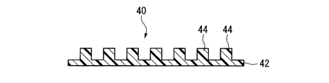
- a molded body 40 having a fine pattern 44 on the surface which is composed only of the cured product 42 having the surface to which the reverse pattern of the mold is transferred, is obtained.
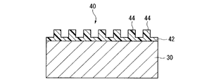
- a molded body 40 having a fine pattern 44 on the surface which is composed of a cured product 42 having a surface to which a reversal pattern of the mold is transferred, and the substrate 30 ( A laminate) is obtained.
- Examples of the molded article having a fine pattern on the surface include the following articles.
- Optical element microlens array, optical waveguide element, optical switching element (grid polarization element, wave plate, etc.), Fresnel zone plate element, binary element, blaze element, photonic crystal, etc.
- Antireflective member AR (Anti Reflection) coating member, etc.
- Chips biochip, micro-total analysis system ( ⁇ -TAS) chip, microreactor chip, etc. Others: recording media, display materials, catalyst carriers, filters, sensor members, resists used in the manufacture of semiconductor devices, daughter molds for nanoimprinting, etc.
- Transparent means that the transmittance is 90% or more and the scattering (haze value) is 1% or less in the visible light region.
- the refractive index of the cured product was determined as follows. A photocurable material is developed to a thickness of 100 ⁇ m with a doctor blade, and a high pressure mercury lamp (light source having dominant wavelengths at 255, 315, and 365 nm at 1.5 to 2.0 kHz) in an N 2 gas atmosphere. Was irradiated with light of 10 mW for 30 minutes to obtain a cured product. The cured product was carefully peeled off and the refractive index at a wavelength of 589 nm was measured at 23 ° C. with an Abbe refractive index measurement device (manufactured by ATAGO, 2T type) with a cutter knife having a size of 8 mm ⁇ 24 mm. .
- the transmittance and haze of the cured product were measured as follows. A photocurable material is filled between two synthetic quartz substrates (thickness: 1 mm, transmittance: 95%) with a spacer having a thickness of 20 ⁇ m interposed therebetween, and a high pressure mercury lamp (1.5-2. Light from a light source having a dominant wavelength at 255, 315, and 365 nm at 0 kHz was irradiated for 10 minutes at an output of 10 mW and cured. Using this as it was, the transmittance and haze were measured with the following apparatus. For comparison, two synthetic quartz substrates with only spacers interposed were used.
- the transmittance was judged to be good when it was 90% or higher at 400 nm and the haze was 1.0% or lower.
- Transmittance Spectrometer (Hitachi Ltd., U-4100), Haze: Haze meter (manufactured by Suga Test Instruments Co., Ltd., HGM-3K).
- the sensitivity of the photocurable material was determined as follows. A photocurable material is applied by spin coating so as to have a thickness of about 1.5 ⁇ m, from which a high pressure mercury lamp (light source having dominant wavelengths at 254, 315, and 365 nm at 1.5 to 2.0 kHz) is applied. The total amount of light until the film was completely cured was obtained and used as the sensitivity. Whether or not the photocurable material was completely cured was determined by measuring the IR spectrum and by the presence or absence of olefin absorption in the acrylic portion. The sensitivity was judged to be good when the value was 1000 mJ / cm 2 or less.
- the contact angle of the cured product with respect to water was measured as follows.
- the photocurable material was irradiated with light from a high-pressure mercury lamp (a light source having a dominant wavelength of 254, 315, and 365 nm at 1.5 to 2.0 kHz) for 15 seconds to obtain a cured product.
- the cured product was measured using a contact angle meter (CA-X150 type, manufactured by Kyowa Interface Science Co., Ltd.) by dropping 4 ⁇ L of water on the surface of the cured product according to JIS R3257.
- the contact angle is a measure of the releasability of the cured product. The contact angle was judged to be good when it was 75 degrees or more.
- the pKa of the compound (B) in the present invention is a value at 20 ° C.
- the pH of the 0.1 mol / L aqueous solution of the compound (B) is measured with a pH meter (C62, manufactured by AS ONE). Calculated from the measured values.
- a pH meter C62, manufactured by AS ONE.
- As the pH 7 standard solution a neutral phosphate standard solution according to JIS Z 8802 was used, and as the pH 4 standard solution, a phthalic acid standard solution according to JIS Z 8802 was used.
- the measurement temperature was 20 ° C.
- Compound (B) Compound (B-1): N-acetylcysteine, molecular weight: 163.2, pKa: 3.27.
- Inorganic fine particles (D) Dispersion of titanium oxide fine particles (D-1): manufactured by Ishihara Sangyo Co., Ltd., trade name: STS-01, average primary particle size: about 5 nm, titanium oxide content: 30.1% by mass, specific gravity: 1.322.
- Compound (f) Compound (f1-1): manufactured by Shin-Nakamura Chemical Co., Ltd., trade name: NPG (neopentyl glycol dimethacrylate).
- Photopolymerization initiator (G) Photopolymerization initiator (G-1): Ciba Geigy Specialty, trade name: Irgacure 651
- Example 1 In a vial container (internal volume 6 mL), 1.52 g of compound (f1-1), 0.88 g of compound (f2-2) and 1.44 g of compound (f3-1) were placed, and 0.2 ⁇ m of polyethylene Filtration through a filter made of terephthalate (hereinafter referred to as PTFE) gave a polymerizable component (F-1) (specific gravity: 1.05). 1.0 mL of the dispersion of titanium oxide fine particles (D-1) was diluted with 9.0 mL of water to obtain an aqueous dispersion of titanium oxide fine particles (D-1).
- PTFE polymerizable component
- MEK methyl ethyl ketone
- Example 1 The raw material charge ratio in Example 1 is shown in Table 1. Various evaluation was performed about the photocurable material (1). The results are shown in Table 2. From the results in Table 2, it was confirmed that the titanium oxide fine particles (D-1) were dispersed without being aggregated in the photocurable material (1).
- Example 2 In the same manner as in Example 1, polymerizable component (F-1) was obtained. 1.2 mL of the dispersion of zirconium oxide fine particles (D-2) was diluted with 3.8 mL of water to obtain an aqueous dispersion of zirconium oxide fine particles (D-2).
- Example 2 The raw material charge ratio in Example 2 is shown in Table 1. Various evaluation was performed about the photocurable material (2). The results are shown in Table 2. From the results in Table 2, it was confirmed that the zirconium oxide fine particles (D-2) were dispersed without being aggregated in the photocurable material (2).
- Example 3 In the same manner as in Example 1, polymerizable component (F-1) was obtained. 1.2 mL of the dispersion of fine titanium oxide particles (D-1) was diluted with 3.8 mL of water to obtain an aqueous dispersion of fine titanium oxide particles (D-1).
- the extract of the surface-modified inorganic fine particles (E′-3) was concentrated under reduced pressure while adding 200 ⁇ L of the polymerizable component (F-1), but as the concentration progressed, the fine particles aggregated and became opaque. Interrupted. In this method, the fine particles could not be stably dispersed in the polymerizable component (F-1).
- Example 4 In the same manner as in Example 1, an aqueous dispersion of titanium oxide fine particles (D-1) was obtained. 120 mg of compound (B-1) was placed in a container, and 3 mL of MEK was added and dissolved to obtain a solution of compound (B-1).
- the aqueous dispersion of the titanium oxide fine particles (D-1) and the solution of the compound (B-1) were stirred, mixed and allowed to stand, the mixture was separated into two phases, the upper phase being the MEK phase, The lower phase became the aqueous phase.
- the titanium oxide fine particles (D-1) were suspended as an opaque white solid between the upper phase and the lower phase. In this method, the titanium oxide fine particles (D-1) in the dispersion could not be extracted into the MEK phase.
- Example 5 In the same manner as in Example 1, an aqueous dispersion of titanium oxide fine particles (D-1) was obtained.
- Example 6 At 25 ° C., one drop of the photocurable material (1) of Example 1 was dropped on the silicon wafer to obtain a silicon wafer on which the material was uniformly applied. A quartz mold having a recess having a width of 800 nm, a depth of 180 nm, and a length of 10 ⁇ m on the surface was pressed against the photocurable material on the silicon wafer and pressed as it was at 0.5 MPa (gauge pressure).
- the photocurable material was irradiated with light from a high-pressure mercury lamp (a light source having a dominant wavelength at 255, 315, and 365 nm at 1.5 to 2.0 kHz) from the mold side for 15 seconds.
- a cured product of a photocurable material was obtained.
- the mold was separated from the silicon wafer to obtain a molded body in which a cured product having convex portions on the surface where the concave portions of the mold were inverted was formed on the surface of the silicon wafer.
- the height from the bottom surface to the top surface of the convex portion was 178 to 180 nm.
- Example 7 In the same manner as in Example 1, polymerizable component (F-1) was obtained. 0.95 mL of the dispersion of titanium oxide fine particles (D-1) was diluted with 9 mL of water to obtain an aqueous dispersion of titanium oxide fine particles (D-1).
- Example 7 The raw material charge ratio in Example 7 is shown in Table 1. Various evaluation was performed about the photocurable material (7). The results are shown in Table 2. From the results in Table 2, it was confirmed that the titanium oxide fine particles (D-1) were dispersed without being aggregated in the photocurable material (7).
- Example 8 In the same manner as in Example 1, polymerizable component (F-1) was obtained. 1.13 mL of the dispersion of zirconium oxide fine particles (D-2) was diluted with 3.9 mL of water to obtain an aqueous dispersion of zirconium oxide fine particles (D-2).
- Step (iii) The extract of the surface-modified inorganic fine particles (E-8) was concentrated under reduced pressure, 440 ⁇ L of the polymerizable component (F-1) was added in the middle, and further concentrated under reduced pressure to remove the solvent to obtain a translucent viscous liquid. 10 mg of the photopolymerization initiator (G-1) was added to obtain a photocurable material (8).
- the mass% of the zirconium oxide fine particles (D-2) in the photocurable material (8) is calculated as 37 masses when the total amount of the zirconium oxide fine particles (D-2) is transferred to the MEK phase in the step (ii). %Met.
- Example 8 The raw material charge ratio in Example 8 is shown in Table 1. Various evaluation was performed about the photocurable material (8). The results are shown in Table 2. From the results in Table 2, it was confirmed that the zirconium oxide fine particles (D-2) were dispersed without being aggregated in the photocurable material (8).
- Example 9 In the same manner as in Example 1, polymerizable component (F-1) was obtained. 9.8 mL of the dispersion of zirconium oxide fine particles (D-2) was diluted with 10.2 mL of water to obtain an aqueous dispersion of zirconium oxide fine particles (D-2).
- Step (iii) The extract of the surface-modified inorganic fine particles (E-9) was concentrated under reduced pressure, and 100 ⁇ L of the polymerizable component (F-1) was added along the way, and further concentrated under reduced pressure to remove the solvent to obtain a translucent viscous liquid. 15 mg of the photopolymerization initiator (G-1) was added to obtain a photocurable material (9). The mass% of the zirconium oxide fine particles (D-2) in the photocurable material (9) is calculated as 73 masses when the total amount of the zirconium oxide fine particles (D-2) is transferred to the MEK phase in the step (ii). %Met.
- Example 9 The raw material charge ratio in Example 9 is shown in Table 1. Various evaluation was performed about the photocurable material (9). The results are shown in Table 2. From the results in Table 2, it was confirmed that the zirconium oxide fine particles (D-2) were dispersed without being aggregated in the photocurable material (9).
- Example 10 7.23 mL of the dispersion of zirconium oxide fine particles (D-2) was diluted with 12.77 mL of water to obtain an aqueous dispersion of zirconium oxide fine particles (D-2).
- D-2 zirconium oxide fine particles
- C-10 solution of the surface modifier
- Step (iii) The extract of the surface-modified inorganic fine particles (E-10) was concentrated under reduced pressure, and 180 ⁇ L of the compound (f2-2) was added along the way, and further concentrated under reduced pressure to remove the solvent. 3 mg of the photopolymerization initiator (G-1) was added to obtain a photocurable material (10). The mass% of the zirconium oxide fine particles (D-2) in the photocurable material (10) is calculated as 60 mass when the total amount of the zirconium oxide fine particles (D-2) is transferred to the MEK phase in the step (ii). %Met.
- Example 10 The raw material charge ratio in Example 10 is shown in Table 1. Various evaluation was performed about the photocurable material (10). The results are shown in Table 2. From the results in Table 2, it was confirmed that the zirconium oxide fine particles (D-2) were dispersed without being aggregated in the photocurable material (10).
- Example 11 7.23 mL of the dispersion of zirconium oxide fine particles (D-2) was diluted with 12.77 mL of water to obtain an aqueous dispersion of zirconium oxide fine particles (D-2).
- Step (iii) The extract of the surface-modified inorganic fine particles (E-11) was concentrated under reduced pressure, and 164 ⁇ L of compound (f2-2) and 16 ⁇ L of compound (f2-3) were added along the way, and concentrated under reduced pressure to remove the solvent. A clear viscous liquid was obtained. 3 mg of the photopolymerization initiator (G-1) was added to obtain a photocurable material (11). The mass% of the zirconium oxide fine particles (D-2) in the photocurable material (11) is calculated as 60 mass when the total amount of the zirconium oxide fine particles (D-2) is transferred to the MEK phase in the step (ii). %Met.
- Example 11 The raw material charge ratios in Example 11 are shown in Table 1. Various evaluation was performed about the photocurable material (11). The results are shown in Table 2. From the results of Table 2, it was confirmed that the zirconium oxide fine particles (D-2) were dispersed without being aggregated in the photocurable material (11).
- Articles obtained using the photocurable material of the present invention include microlens arrays, optical waveguide elements, optical switching elements (grid polarizing elements, wave plates, etc.), Fresnel zone plate elements, binary elements, blazed elements, and photonics. It is useful as an optical element such as a crystal, an antireflection member, a production replica mold, or the like.
- Photocurable material 30
- Base material 40
- Molded body (article) 42
Landscapes
- Chemical & Material Sciences (AREA)
- Health & Medical Sciences (AREA)
- Chemical Kinetics & Catalysis (AREA)
- Medicinal Chemistry (AREA)
- Polymers & Plastics (AREA)
- Organic Chemistry (AREA)
- Engineering & Computer Science (AREA)
- Inorganic Chemistry (AREA)
- Materials Engineering (AREA)
- Physics & Mathematics (AREA)
- General Physics & Mathematics (AREA)
- Optics & Photonics (AREA)
- Polymerisation Methods In General (AREA)
- Graft Or Block Polymers (AREA)
- Addition Polymer Or Copolymer, Post-Treatments, Or Chemical Modifications (AREA)
Abstract
Priority Applications (4)
| Application Number | Priority Date | Filing Date | Title |
|---|---|---|---|
| EP20090833437 EP2360195B1 (fr) | 2008-12-15 | 2009-12-15 | Procédé de fabrication de matériau photo-durcissable, matériau photodurcissable et article |
| CN2009801497979A CN102245663B (zh) | 2008-12-15 | 2009-12-15 | 光固化性材料的制造方法、光固化性材料以及物品 |
| JP2010542977A JPWO2010071134A1 (ja) | 2008-12-15 | 2009-12-15 | 光硬化性材料の製造方法、光硬化性材料および物品 |
| US13/152,740 US8207242B2 (en) | 2008-12-15 | 2011-06-03 | Process for producing photocurable material, photocurable material and article |
Applications Claiming Priority (4)
| Application Number | Priority Date | Filing Date | Title |
|---|---|---|---|
| JP2008318895 | 2008-12-15 | ||
| JP2008-318895 | 2008-12-15 | ||
| JP2009157257 | 2009-07-01 | ||
| JP2009-157257 | 2009-07-01 |
Related Child Applications (1)
| Application Number | Title | Priority Date | Filing Date |
|---|---|---|---|
| US13/152,740 Continuation US8207242B2 (en) | 2008-12-15 | 2011-06-03 | Process for producing photocurable material, photocurable material and article |
Publications (1)
| Publication Number | Publication Date |
|---|---|
| WO2010071134A1 true WO2010071134A1 (fr) | 2010-06-24 |
Family
ID=42268805
Family Applications (1)
| Application Number | Title | Priority Date | Filing Date |
|---|---|---|---|
| PCT/JP2009/070917 Ceased WO2010071134A1 (fr) | 2008-12-15 | 2009-12-15 | Procédé de fabrication de matériau photo-durcissable, matériau photodurcissable et article |
Country Status (6)
| Country | Link |
|---|---|
| US (1) | US8207242B2 (fr) |
| EP (1) | EP2360195B1 (fr) |
| JP (1) | JPWO2010071134A1 (fr) |
| KR (1) | KR20110110107A (fr) |
| CN (1) | CN102245663B (fr) |
| WO (1) | WO2010071134A1 (fr) |
Cited By (7)
| Publication number | Priority date | Publication date | Assignee | Title |
|---|---|---|---|---|
| JP2011012163A (ja) * | 2009-07-01 | 2011-01-20 | Asahi Glass Co Ltd | 光硬化性材料の製造方法、光硬化性材料および物品 |
| JP2012255148A (ja) * | 2011-05-18 | 2012-12-27 | Fujifilm Corp | 分散組成物、これを用いた硬化性組成物、透明膜、マイクロレンズ、及び固体撮像素子、並びに透明膜の製造方法、マイクロレンズの製造方法、及び固体撮像素子の製造方法 |
| WO2017195598A1 (fr) * | 2016-05-10 | 2017-11-16 | 横浜ゴム株式会社 | Composition de résine durcissable aux ultraviolets, film durci et stratifié |
| JP2019183137A (ja) * | 2018-03-30 | 2019-10-24 | 三菱ケミカル株式会社 | 無機酸化物粒子又はシロキサン化合物を含む重合性組成物、該重合性組成物を用いた層の製造方法及び無機酸化物粒子又はシロキサン化合物を含む層 |
| US10745508B2 (en) | 2015-12-25 | 2020-08-18 | AGC Inc. | Surface-modified metal oxide particles, production method, dispersion liquid, curable composition, and cured product |
| WO2022158568A1 (fr) * | 2021-01-22 | 2022-07-28 | 日揮触媒化成株式会社 | Liquide de revêtement, procédé de production associé et procédé de production de substrat pourvu d'un film |
| JPWO2022230871A1 (fr) * | 2021-04-30 | 2022-11-03 |
Families Citing this family (7)
| Publication number | Priority date | Publication date | Assignee | Title |
|---|---|---|---|---|
| JP2015056186A (ja) | 2013-09-10 | 2015-03-23 | 株式会社東芝 | パターン形成方法、及び磁気記録媒体の製造方法 |
| WO2016048358A1 (fr) * | 2014-09-26 | 2016-03-31 | Hewlett-Packard Development Company, L.P. | Composition d'encre photodurcissable non newtonienne |
| US10844233B2 (en) | 2014-09-26 | 2020-11-24 | Hewlett-Packard Development Company, L.P. | Non-Newtonian photo-curable ink composition |
| WO2016048360A1 (fr) | 2014-09-26 | 2016-03-31 | Hewlett-Packard Development Company, L.P. | Composition d'encre photodurcissable non newtonienne |
| US10392523B2 (en) | 2014-12-11 | 2019-08-27 | Hewlett-Packard Development Company, L.P. | Non-Newtonian photo-curable ink composition |
| CN109232838B (zh) * | 2018-08-06 | 2021-04-06 | 浙江工业大学 | 一种新型可生物降解的快速光固化成型材料的制备方法 |
| KR102400603B1 (ko) * | 2019-03-29 | 2022-05-19 | 삼성에스디아이 주식회사 | 레지스트 하층막용 조성물 및 이를 이용한 패턴 형성 방법 |
Citations (8)
| Publication number | Priority date | Publication date | Assignee | Title |
|---|---|---|---|---|
| US6696220B2 (en) | 2000-10-12 | 2004-02-24 | Board Of Regents, The University Of Texas System | Template for room temperature, low pressure micro-and nano-imprint lithography |
| JP2004071934A (ja) | 2002-08-08 | 2004-03-04 | Kanegafuchi Chem Ind Co Ltd | 微細パターンの製造方法および転写材料 |
| JP2006182880A (ja) * | 2004-12-27 | 2006-07-13 | Mitsubishi Rayon Co Ltd | 硬化性組成物 |
| JP2006273709A (ja) * | 2005-03-03 | 2006-10-12 | Mitsubishi Chemicals Corp | 高屈折率を有するナノ粒子 |
| JP2007314773A (ja) | 2006-04-28 | 2007-12-06 | Mitsubishi Chemicals Corp | 高屈折率粒子含有樹脂組成物 |
| JP2008156479A (ja) * | 2006-12-25 | 2008-07-10 | Fujifilm Corp | 硬化性組成物、それを用いて形成されたフィルム、ならびに該フィルムを有する偏光板及び液晶表示装置 |
| JP2008163252A (ja) * | 2006-12-28 | 2008-07-17 | Dainippon Printing Co Ltd | 防眩層用硬化性樹脂組成物、及び防眩フィルム |
| JP2008201853A (ja) | 2007-02-16 | 2008-09-04 | Hoya Corp | 酸化チタン粒子含有非水性分散液の製造方法 |
Family Cites Families (2)
| Publication number | Priority date | Publication date | Assignee | Title |
|---|---|---|---|---|
| WO2002035555A1 (fr) * | 2000-10-23 | 2002-05-02 | Sekisui Chemical Co., Ltd. | Particule enrobee |
| WO2008068154A2 (fr) * | 2006-12-06 | 2008-06-12 | Ciba Holding Inc. | Changement de propriétés de surface par des nanoparticules fonctionnalisées |
-
2009
- 2009-12-15 JP JP2010542977A patent/JPWO2010071134A1/ja not_active Withdrawn
- 2009-12-15 KR KR1020117013179A patent/KR20110110107A/ko not_active Withdrawn
- 2009-12-15 EP EP20090833437 patent/EP2360195B1/fr not_active Not-in-force
- 2009-12-15 CN CN2009801497979A patent/CN102245663B/zh not_active Expired - Fee Related
- 2009-12-15 WO PCT/JP2009/070917 patent/WO2010071134A1/fr not_active Ceased
-
2011
- 2011-06-03 US US13/152,740 patent/US8207242B2/en not_active Expired - Fee Related
Patent Citations (8)
| Publication number | Priority date | Publication date | Assignee | Title |
|---|---|---|---|---|
| US6696220B2 (en) | 2000-10-12 | 2004-02-24 | Board Of Regents, The University Of Texas System | Template for room temperature, low pressure micro-and nano-imprint lithography |
| JP2004071934A (ja) | 2002-08-08 | 2004-03-04 | Kanegafuchi Chem Ind Co Ltd | 微細パターンの製造方法および転写材料 |
| JP2006182880A (ja) * | 2004-12-27 | 2006-07-13 | Mitsubishi Rayon Co Ltd | 硬化性組成物 |
| JP2006273709A (ja) * | 2005-03-03 | 2006-10-12 | Mitsubishi Chemicals Corp | 高屈折率を有するナノ粒子 |
| JP2007314773A (ja) | 2006-04-28 | 2007-12-06 | Mitsubishi Chemicals Corp | 高屈折率粒子含有樹脂組成物 |
| JP2008156479A (ja) * | 2006-12-25 | 2008-07-10 | Fujifilm Corp | 硬化性組成物、それを用いて形成されたフィルム、ならびに該フィルムを有する偏光板及び液晶表示装置 |
| JP2008163252A (ja) * | 2006-12-28 | 2008-07-17 | Dainippon Printing Co Ltd | 防眩層用硬化性樹脂組成物、及び防眩フィルム |
| JP2008201853A (ja) | 2007-02-16 | 2008-09-04 | Hoya Corp | 酸化チタン粒子含有非水性分散液の製造方法 |
Non-Patent Citations (2)
| Title |
|---|
| "Preparation of a nanocomposite of high refractive index thioacrylate resin/Ti02-Zr02 ultrafine particles and its characterization", POLYMER PREPRINTS, vol. 57, no. 2, 2008, pages 3480 - 3481 |
| See also references of EP2360195A4 |
Cited By (9)
| Publication number | Priority date | Publication date | Assignee | Title |
|---|---|---|---|---|
| JP2011012163A (ja) * | 2009-07-01 | 2011-01-20 | Asahi Glass Co Ltd | 光硬化性材料の製造方法、光硬化性材料および物品 |
| JP2012255148A (ja) * | 2011-05-18 | 2012-12-27 | Fujifilm Corp | 分散組成物、これを用いた硬化性組成物、透明膜、マイクロレンズ、及び固体撮像素子、並びに透明膜の製造方法、マイクロレンズの製造方法、及び固体撮像素子の製造方法 |
| US10745508B2 (en) | 2015-12-25 | 2020-08-18 | AGC Inc. | Surface-modified metal oxide particles, production method, dispersion liquid, curable composition, and cured product |
| WO2017195598A1 (fr) * | 2016-05-10 | 2017-11-16 | 横浜ゴム株式会社 | Composition de résine durcissable aux ultraviolets, film durci et stratifié |
| JP2019183137A (ja) * | 2018-03-30 | 2019-10-24 | 三菱ケミカル株式会社 | 無機酸化物粒子又はシロキサン化合物を含む重合性組成物、該重合性組成物を用いた層の製造方法及び無機酸化物粒子又はシロキサン化合物を含む層 |
| WO2022158568A1 (fr) * | 2021-01-22 | 2022-07-28 | 日揮触媒化成株式会社 | Liquide de revêtement, procédé de production associé et procédé de production de substrat pourvu d'un film |
| JP7169493B1 (ja) * | 2021-01-22 | 2022-11-10 | 日揮触媒化成株式会社 | 塗布液及びその製造方法、膜付基材の製造方法 |
| JPWO2022230871A1 (fr) * | 2021-04-30 | 2022-11-03 | ||
| WO2022230871A1 (fr) * | 2021-04-30 | 2022-11-03 | 東京応化工業株式会社 | Composition durcissable et procédé de formation de motif |
Also Published As
| Publication number | Publication date |
|---|---|
| CN102245663A (zh) | 2011-11-16 |
| KR20110110107A (ko) | 2011-10-06 |
| EP2360195A4 (fr) | 2012-05-23 |
| US8207242B2 (en) | 2012-06-26 |
| CN102245663B (zh) | 2013-09-04 |
| EP2360195B1 (fr) | 2013-02-20 |
| EP2360195A1 (fr) | 2011-08-24 |
| US20110237703A1 (en) | 2011-09-29 |
| JPWO2010071134A1 (ja) | 2012-05-31 |
Similar Documents
| Publication | Publication Date | Title |
|---|---|---|
| CN102245663B (zh) | 光固化性材料的制造方法、光固化性材料以及物品 | |
| JP5594147B2 (ja) | 光硬化性組成物および表面に微細パターンを有する成形体の製造方法 | |
| JP5617632B2 (ja) | 光硬化性組成物および表面に微細パターンを有する成形体の製造方法 | |
| JP5387406B2 (ja) | 表面に微細パターンを有する成形体の製造方法 | |
| CN101160331B (zh) | 光固化性组合物、精细图案形成体及其制造方法 | |
| JP5182644B2 (ja) | ワイヤグリッド型偏光子およびその製造方法 | |
| JP5315263B2 (ja) | 光硬化性組成物および表面に微細パターンを有する成形体の製造方法 | |
| JP2013245229A (ja) | インプリント用光硬化性組成物および微細パターンを表面に有する成形体の製造方法 | |
| CN108368211B (zh) | 固化性组合物及固化物 | |
| JP5647829B2 (ja) | 光硬化性組成物および表面に微細パターンを有する成形体の製造方法 | |
| JP2007001250A (ja) | 微細パターン形成体の製造方法 | |
| WO2012017530A1 (fr) | Composition photodurcissable et procédé pour la production d'un corps moulé ayant une surface qui est dotée d'un motif fin | |
| JP2011012163A (ja) | 光硬化性材料の製造方法、光硬化性材料および物品 | |
| JP2011016351A (ja) | 子モールドの製造方法および物品の製造方法 | |
| JP5471084B2 (ja) | 光硬化性材料の製造方法、光硬化性材料および物品 | |
| JP6880793B2 (ja) | インプリント用光硬化性組成物、微細パターンを表面に有する物品およびその製造方法 |
Legal Events
| Date | Code | Title | Description |
|---|---|---|---|
| WWE | Wipo information: entry into national phase |
Ref document number: 200980149797.9 Country of ref document: CN |
|
| 121 | Ep: the epo has been informed by wipo that ep was designated in this application |
Ref document number: 09833437 Country of ref document: EP Kind code of ref document: A1 |
|
| ENP | Entry into the national phase |
Ref document number: 2010542977 Country of ref document: JP Kind code of ref document: A |
|
| WWE | Wipo information: entry into national phase |
Ref document number: 2009833437 Country of ref document: EP |
|
| ENP | Entry into the national phase |
Ref document number: 20117013179 Country of ref document: KR Kind code of ref document: A |
|
| NENP | Non-entry into the national phase |
Ref country code: DE |