WO2010073607A1 - 回転検出装置および回転検出装置付き軸受 - Google Patents
回転検出装置および回転検出装置付き軸受 Download PDFInfo
- Publication number
- WO2010073607A1 WO2010073607A1 PCT/JP2009/007100 JP2009007100W WO2010073607A1 WO 2010073607 A1 WO2010073607 A1 WO 2010073607A1 JP 2009007100 W JP2009007100 W JP 2009007100W WO 2010073607 A1 WO2010073607 A1 WO 2010073607A1
- Authority
- WO
- WIPO (PCT)
- Prior art keywords
- magnetic
- phase
- signal
- output
- rotation
- Prior art date
- Legal status (The legal status is an assumption and is not a legal conclusion. Google has not performed a legal analysis and makes no representation as to the accuracy of the status listed.)
- Ceased
Links
Images






Classifications
-
- G—PHYSICS
- G01—MEASURING; TESTING
- G01D—MEASURING NOT SPECIALLY ADAPTED FOR A SPECIFIC VARIABLE; ARRANGEMENTS FOR MEASURING TWO OR MORE VARIABLES NOT COVERED IN A SINGLE OTHER SUBCLASS; TARIFF METERING APPARATUS; MEASURING OR TESTING NOT OTHERWISE PROVIDED FOR
- G01D5/00—Mechanical means for transferring the output of a sensing member; Means for converting the output of a sensing member to another variable where the form or nature of the sensing member does not constrain the means for converting; Transducers not specially adapted for a specific variable
- G01D5/12—Mechanical means for transferring the output of a sensing member; Means for converting the output of a sensing member to another variable where the form or nature of the sensing member does not constrain the means for converting; Transducers not specially adapted for a specific variable using electric or magnetic means
- G01D5/244—Mechanical means for transferring the output of a sensing member; Means for converting the output of a sensing member to another variable where the form or nature of the sensing member does not constrain the means for converting; Transducers not specially adapted for a specific variable using electric or magnetic means influencing characteristics of pulses or pulse trains; generating pulses or pulse trains
- G01D5/245—Mechanical means for transferring the output of a sensing member; Means for converting the output of a sensing member to another variable where the form or nature of the sensing member does not constrain the means for converting; Transducers not specially adapted for a specific variable using electric or magnetic means influencing characteristics of pulses or pulse trains; generating pulses or pulse trains using a variable number of pulses in a train
- G01D5/2454—Encoders incorporating incremental and absolute signals
- G01D5/2455—Encoders incorporating incremental and absolute signals with incremental and absolute tracks on the same encoder
- G01D5/2457—Incremental encoders having reference marks
-
- F—MECHANICAL ENGINEERING; LIGHTING; HEATING; WEAPONS; BLASTING
- F16—ENGINEERING ELEMENTS AND UNITS; GENERAL MEASURES FOR PRODUCING AND MAINTAINING EFFECTIVE FUNCTIONING OF MACHINES OR INSTALLATIONS; THERMAL INSULATION IN GENERAL
- F16C—SHAFTS; FLEXIBLE SHAFTS; ELEMENTS OR CRANKSHAFT MECHANISMS; ROTARY BODIES OTHER THAN GEARING ELEMENTS; BEARINGS
- F16C41/00—Other accessories, e.g. devices integrated in the bearing not relating to the bearing function as such
- F16C41/007—Encoders, e.g. parts with a plurality of alternating magnetic poles
-
- G—PHYSICS
- G01—MEASURING; TESTING
- G01D—MEASURING NOT SPECIALLY ADAPTED FOR A SPECIFIC VARIABLE; ARRANGEMENTS FOR MEASURING TWO OR MORE VARIABLES NOT COVERED IN A SINGLE OTHER SUBCLASS; TARIFF METERING APPARATUS; MEASURING OR TESTING NOT OTHERWISE PROVIDED FOR
- G01D5/00—Mechanical means for transferring the output of a sensing member; Means for converting the output of a sensing member to another variable where the form or nature of the sensing member does not constrain the means for converting; Transducers not specially adapted for a specific variable
- G01D5/12—Mechanical means for transferring the output of a sensing member; Means for converting the output of a sensing member to another variable where the form or nature of the sensing member does not constrain the means for converting; Transducers not specially adapted for a specific variable using electric or magnetic means
- G01D5/244—Mechanical means for transferring the output of a sensing member; Means for converting the output of a sensing member to another variable where the form or nature of the sensing member does not constrain the means for converting; Transducers not specially adapted for a specific variable using electric or magnetic means influencing characteristics of pulses or pulse trains; generating pulses or pulse trains
- G01D5/245—Mechanical means for transferring the output of a sensing member; Means for converting the output of a sensing member to another variable where the form or nature of the sensing member does not constrain the means for converting; Transducers not specially adapted for a specific variable using electric or magnetic means influencing characteristics of pulses or pulse trains; generating pulses or pulse trains using a variable number of pulses in a train
- G01D5/2451—Incremental encoders
- G01D5/2452—Incremental encoders incorporating two or more tracks having an (n, n+1, ...) relationship
Definitions
- the present invention relates to a rotation detection device used for rotation angle detection in various devices, particularly rotation angle detection for rotation control of various motors, and a bearing with a rotation detection device equipped with the rotation detection device.
- Patent Document 2 As another rotation detection device, one that obtains a two-phase magnetic field signal has been proposed (for example, Patent Document 2).
- This includes a ring-shaped magnetic pulse generating means such as a magnetic encoder in which magnetic pole pairs are arranged in the circumferential direction for generating a magnetic pulse, and the magnetic pulse substantially aligned in the circumferential direction with respect to the magnetic pulse generating means.
- a plurality of detection elements for detection, and an absolute angle is detected by calculating an output signal of the detection elements.
- Patent Document 3 As another rotation detection device, one that executes a mode of outputting an absolute angle using an ABZ phase signal has been proposed (for example, Patent Document 3).
- Patent Document 4 there is no description of a signal form for transmitting each detected magnetic phase signal to a phase difference detection circuit in a configuration for calculating an absolute angle from magnetic phases detected by a plurality of magnetic sensors.
- the phase of the detected magnetic field signal is accurately transmitted with less wiring without being disturbed by noise in order to perform absolute angle detection with high accuracy. This is necessary for absolute angle detection.
- Patent Document 4 does not disclose a signal form for transmitting the phase of the magnetic field signal detected by each magnetic sensor to the phase difference detection circuit.
- An object of the present invention is to provide a rotation detection device that is resistant to noise and can accurately detect an absolute angle even during high-speed rotation, and a bearing with a rotation detection device equipped with the rotation detection device.
- the rotation detection device of the present invention includes a plurality of magnetic encoders that are provided in concentric rings and have different numbers of magnetic poles, and a plurality of magnetic sensors that respectively detect the magnetic fields of these magnetic encoders.
- a rotation detecting device having a function of detecting position information in a magnetic pole of an encoder, wherein each of the magnetic sensors obtains a phase from a plurality of sensor elements and a magnetic field signal detected by the sensor elements.
- a phase difference detecting means for obtaining a phase difference between the magnetic field signals from the output of the means, and calculating an absolute angle of the magnetic encoder based on the detected phase difference. It is provided and an angle calculation means.
- the plurality of magnetic sensors may be mounted on a wiring board or other means in an individually packaged form, and may be connected to the phase difference detecting means by wiring on the wiring board or independent wiring. According to this configuration, the phase of the magnetic field signal detected by each magnetic sensor is transmitted to the phase difference detection means as an ABZ phase signal instead of an analog signal. Therefore, it can withstand noise and transmit at high speed, and the number of main lines of wiring can be reduced.
- the advantage of being able to transmit the magnetic field signal from the magnetic sensor to the phase difference detection means is strong against noise and can be transmitted more effectively.
- there is no communication protocol overhead so that rotation information can be transmitted in a minimum time.
- At least one of the plurality of magnetic encoders having different numbers of magnetic poles is formed of a plurality of tracks, and a phase shift pattern for generating an index signal is formed at a specific position of these tracks.
- the magnetic sensor detects a phase shift and outputs an index signal as a Z-phase signal.
- the phase difference detecting means can reset or set a counter for counting the A-phase signal and the B-phase signal to a prescribed value. For this reason, even when erroneously counted due to the influence of noise or the like, there is no influence after resetting or after setting to the specified value. For this reason, retention of errors can be prevented.
- phase shift patterns for generating the index signal are formed at equal intervals by a number equal to the difference n in the number of magnetic pole pairs between the magnetic encoders, and n (n is a natural number) per one rotation of the magnetic encoder. ) May be configured to output a Z-phase signal.
- the phase shift pattern for generating the index signal may be formed in all the magnetic pole pairs in a plurality of tracks, and may be configured to output a Z-phase signal for each magnetic pole pair. In this case, the configuration is equivalent to a configuration in which the magnetic sensor itself can detect the phase in the magnetic pole and output the ABZ signal.
- the phase detecting means can be switched between an absolute angle output mode for outputting the phase of the magnetic field signal as an absolute angle and a mode for outputting only the A-phase and B-phase pulse signals A and B.
- the absolute angle output mode execution means may be provided. By enabling mode switching in this way, the processing of the output signal can be simplified and the use of the output signal can be diversified.
- an ABZ phase signal external output means for outputting at least one set of signals among the ABZ phase signals output from the phase detection means to the outside of the rotation detection device.
- the rotational speed and the like can be detected using the ABZ phase signal output to the outside by the ABZ phase signal external output means.
- the magnetic sensor has a plurality of sensor elements arranged at positions shifted from each other within the magnetic pole pitch, and can obtain a two-phase signal output of sin and cos. May be detected by interpolation processing using the output signal.
- the plurality of sensor elements may be two, and may be arranged at positions 90 degrees apart from each other at the magnetic pole pitch.
- the magnetic sensor has a line sensor in which sensor elements are arranged along the arrangement direction of the magnetic poles of the magnetic encoder, and generates a two-phase signal output of sin and cos by calculation to determine the position in the magnetic pole. Further, it may be detected by an interpolation calculation process using the output signal.
- the sensor element of the magnetic sensor is configured as such a line sensor, the influence of the distortion of the magnetic field pattern and noise is reduced, and the phase of the magnetic encoder can be detected with higher accuracy.
- angle information output means for outputting the absolute angle information calculated by the angle calculation means as an ABZ phase signal may be provided.
- it is not necessary to separately provide interface means for outputting an absolute angle and the circuit configuration of the rotation detection device and the circuit configuration on the device side on which the rotation detection device is mounted can be simplified.
- the magnetic encoder may be a radial type or an axial type. That is, the magnetic encoder may have each magnetic pole on the outer peripheral surface, and the magnetic sensor element of the magnetic sensor may face the magnetic encoder in the radial direction.
- the magnetic encoder may have each magnetic pole on an axial surface, and the magnetic sensor element of the magnetic sensor may face the magnetic encoder in the axial direction.
- the bearing with a rotation detection device of the present invention is obtained by mounting the rotation detection device of any one of the above configurations of the present invention on a bearing. According to this configuration, it is possible to reduce the number of parts, the number of assembling steps, and the size of the bearing using device.
- FIG. 1 It is a block diagram which shows the example of 1 structure of the angle information output circuit of this rotation detection apparatus.
- A is a block diagram which shows the example of 1 structure of the rotation detection apparatus concerning 2nd Embodiment of this invention
- (B) is a front view of the magnetic encoder of the rotation detection apparatus. It is sectional drawing which shows one Embodiment of the bearing with a rotation detection apparatus which mounted this rotation detection apparatus in the bearing.
- FIG. 1 shows a schematic configuration of the rotation detection device of this embodiment.
- the rotation detection device 1 includes a plurality of (here, two) magnetic encoders 2A and 2B provided in a ring shape concentric with an axis O on the outer periphery of a rotating member 4 such as a rotating shaft of a motor, for example.
- a plurality of (here, two) magnetic sensors 3A and 3B that respectively detect the magnetic fields of the magnetic encoders 2A and 2B are provided.
- FIG. 1 shows a schematic configuration of the rotation detection device of this embodiment.
- the rotation detection device 1 includes a plurality of (here, two) magnetic encoders 2A and 2B provided in a ring shape concentric with an axis O on the outer periphery of a rotating member 4 such as a rotating shaft of a motor, for example.
- a plurality of (here, two) magnetic sensors 3A and 3B that respectively detect the magnetic fields of the magnetic encoders 2A and 2B are provided.
- the magnetic sensors 3A, 3B are fixed members 5 such as motor housings so as to face each of the magnetic encoders 2A, 2B in the radial direction (radial direction) through a minute gap. Is provided.
- the magnetic sensor 3A faces the magnetic encoder 2A
- the magnetic sensor 3B faces the magnetic encoder 2B.
- the magnetic encoders 2A and 2B are ring-shaped magnetic members in which a plurality of magnetic pole pairs (one set of a magnetic pole S and a magnetic pole N) are magnetized at an equal pitch in the circumferential direction.
- a magnetic pole pair is magnetized on the outer peripheral surface.
- the number of magnetic pole pairs of these two magnetic encoders 2A and 2B is different from each other.
- the two magnetic encoders 2A and 2B are arranged adjacent to each other in the axial direction. However, if the magnetic encoders 2A and 2B rotate in the same direction, they are arranged in different locations. You may do it.
- an axial type magnet in which a plurality of magnetic pole pairs are magnetized so as to be arranged at an equal pitch in the circumferential direction on the end surface in the axial direction of a ring-shaped magnetic member May be used.
- the two magnetic encoders 2A and 2B are arranged concentrically so as to be adjacent to the inner and outer circumferences.
- the magnetic sensors 3A and 3B are arranged in the axial direction facing the magnetized surface. Note that the plurality of magnetic encoders 2A and 2B are not necessarily arranged adjacent to each other in both the radial type and the axial type, and may be arranged apart from each other as long as they can rotate integrally. .
- the magnetic sensors 3A and 3B have a function of detecting magnetic poles with a resolution higher than the number of magnetic pole pairs of the corresponding magnetic encoders 2A and 2B, that is, a function of detecting position information within the magnetic pole ranges of the magnetic encoders 2A and 2B. It is supposed to be.
- a sensor element of the magnetic sensor 3A when the pitch ⁇ of one magnetic pole pair of the corresponding magnetic encoder 2A is one cycle, a 90 ° phase difference ( ⁇ / 4) as shown in FIG.
- Two magnetic sensor elements 3A1 and 3A2 such as Hall elements arranged so as to be separated in the direction in which the magnetic poles are arranged may be used.
- the other magnetic sensor 3B is the same as the magnetic sensor 3A.
- the waveform diagram of FIG. 3 shows the magnetic pole array of the magnetic encoder 2A in terms of magnetic field strength.
- the magnetic field distribution of the magnetic encoders 2A and 2B can be detected more finely as a sinusoidal signal based on an analog voltage rather than as an on / off signal, and the absolute accuracy is high. Angle detection is possible.
- a line sensor as shown in FIG. 4B may be used.
- line sensors 3AA and 3AB in which the magnetic sensor elements 3a are arranged along the arrangement direction of the magnetic poles of the corresponding magnetic encoder 2A are used as sensor elements of the magnetic sensor 3A.
- FIG. 4A is a waveform diagram in which one magnetic pole section in the magnetic encoder 2A is converted into a magnetic field strength.
- the first line sensor 3AA of the magnetic sensor 3A is arranged in association with the 90-degree phase section of the 180-degree phase section in FIG.
- the second line sensor 3AB is the remaining 90. It is arranged in correspondence with the phase interval of degrees. With such an arrangement, the signal S1 obtained by adding the detection signal of the first line sensor 3AA by the adder circuit 31 and the signal S2 obtained by adding the detection signal of the second line sensor 3AB by the adder circuit 32 are different adder circuits. By adding at 33, a sin signal corresponding to the magnetic field signal as shown in FIG. Further, the signal S1 and the signal S2 via the inverter 35 are added by another adding circuit 34 to obtain a cos signal corresponding to the magnetic field signal as shown in FIG. The position within the magnetic pole range is detected from the two-phase output signal thus obtained.
- each of the magnetic sensors 3A and 3B obtains their phases from the magnetic field signals detected by the magnetic sensor elements, in addition to the magnetic sensor elements 3A1, 3A2, 3B1, and 3B2.
- Phase detection circuits 13A and 13B for outputting as phase signals are provided.
- the ABZ-phase signal is a signal including A-phase and B-phase pulse signals A and B having a 90 ° phase difference and a Z-phase pulse signal Z indicating the origin position.
- FIG. 7 shows the case of the magnetic sensor elements 3A1, 3A2, 3B1, and 3B2 of the configuration example of FIG. 3 as examples of the sensor elements.
- the magnetic sensors 3 ⁇ / b> A and 3 ⁇ / b> B are connected to the phase difference detection means 6.
- the phase difference detection means 6 is a means for obtaining a phase difference between magnetic field signals detected by the magnetic sensors 3A and 3B, and an angle calculation means 7 is connected to the subsequent stage.
- the angle calculation means 7 is a means for calculating the absolute angle of the magnetic encoders 2A and 2B based on the phase difference detected by the phase difference detection means 6.
- the plurality of magnetic sensors 3A and 3B are provided as separate elements, that is, individually packaged and mounted on a wiring board (not shown) or other means, and the phase difference detecting means 6 and wiring They are connected by wiring on the board or by independent wiring.
- FIG. 1 Schematic operation of absolute angle detection by the rotation detection device 1 will be described below with reference to FIGS. 5 (A) to (E) and FIGS.
- the number of magnetic pole pairs of the two magnetic encoders 2B and 2A is P and P + n
- the phases of the detection signals of the magnetic sensors 3A and 3B corresponding to the magnetic encoders 2A and 2B coincide with each other when rotated 360 / n degrees.
- FIGS. 5A and 5B show examples of magnetic pole patterns of both magnetic encoders 2A and 2B
- FIGS. 5C and 5D show detection signals of magnetic sensors 3A and 3B corresponding to these magnetic encoders.
- the waveform is shown.
- the two magnetic pole pairs of the magnetic encoder 2B correspond to the three magnetic pole pairs of the magnetic encoder 2A, and the absolute position within this section can be detected.
- FIG. 5E shows a waveform diagram of the output signal of the phase difference obtained from the phase difference detecting means 6 of FIG. 1 based on the detection signals of FIGS. 5C and 5D.
- 6A to 6E show waveform diagrams of detection phases and phase differences detected by the magnetic sensors 3A and 3B.
- FIGS. 6A and 6B show examples of magnetic pole patterns of both magnetic encoders 2A and 2B
- FIGS. 6C and 6D show waveforms of detection phases of the corresponding magnetic sensors 3A and 3B.
- FIG. 6E shows a waveform diagram of the phase difference signal output from the phase difference detecting means 6.
- FIG. 7 shows a configuration example of an absolute angle detection circuit in the rotation detection device 1.
- the corresponding phase detection circuits 13A and 13B are shown in FIG.
- Detection phase signals as shown in (C) and (D) are output.
- the detection phase signal is shown as a sawtooth waveform for the sake of simplicity, but the phase detection circuits 13A and 13B output ABZ phase signals (ABZ1 and ABZ2) as detection phase signals, as will be described later.
- the phase difference detection means 6 outputs a phase difference signal as shown in FIG. 6E based on these detected phase signals.
- the angle calculation means 7 provided in the next stage performs a process of converting the phase difference obtained by the phase difference detection means 6 into an absolute angle according to a preset calculation parameter.
- Calculation parameters used in the angle calculation means 7 are stored in a memory 8 such as a nonvolatile memory.
- the memory 8 stores information necessary for the operation of the apparatus, such as setting of the number of magnetic pole pairs of the magnetic encoders 2A and 2B, an absolute angle reference position, and a signal output method.
- the contents of the memory 8 can be updated through the communication interface 9.
- the individual setting information can be variably set according to the use situation, and the usability is improved.
- the absolute angle information calculated by the angle calculation means 7 is output from the angle information output circuit 10 or via the communication I / F 9 as a modulation signal such as a parallel signal, serial data, analog voltage, or PWM. Further, a rotation pulse signal is also output from the angle calculation means 7. As the rotation pulse signal, any one of the detection signals of the two magnetic sensors 3A and 3B may be output. As described above, since each magnetic sensor 3A, 3B has a multiplication function, it is possible to output a rotation signal with high resolution.
- the phase detection circuits 13A and 13B of the magnetic sensors 3A and 3B include the calculated phase information in addition to the angle calculation means 12 that calculates the phases from the magnetic field signals detected by the sensor elements. Is output as an ABZ phase signal and transmitted to the phase difference detecting means 6.
- At least one set of signals (here, the ABZ phase signal ABZ1 output from the phase detection circuit 13A) is an ABZ phase signal external output. It is output to the outside by means 14.
- the ABZ phase signal external output means 14 is configured as another signal circuit that is drawn to the outside from the output of the phase detection circuit 13A. In this way, when the ABZ phase signal is output from the phase detection circuit 13A to the outside without passing through the subsequent phase difference detection means 6 or the like, the ABZ phase signal can be directly used for detecting the rotational speed of the rotating member 4 or the like. it can.
- the angle information output unit 20 includes a rotation pulse signal generation unit 17, an absolute angle output mode execution unit 15, and a mode execution signal generation unit 16.
- the rotation pulse signal generation unit 17 is a unit that generates an ABZ phase signal based on the magnetic phase calculated by the angle calculation unit 12.
- 9A and 9B are waveform diagrams of two pulse signals (A-phase signal and B-phase signal) generated by the rotation pulse signal generation unit 17.
- FIG. 9C shows a waveform diagram of the Z-phase signal generated by the rotation pulse signal generation means 17.
- the absolute angle output mode execution means 15 is an absolute angle output mode which is a mode for outputting the rotation pulse signal (AB phase signal) from the output of the index signal (Z phase signal) to the current magnetic field phase; This means can be switched to a mode in which only the A-phase and B-phase pulse signals A and B are output.
- the rotation pulse signal (AB phase signal) generated by the rotation pulse signal generation means 17 differs between the absolute angle output mode and the non-mode. That is, the rotation pulse signal (AB phase signal) when not in the absolute angle output mode (normal time) is generated as a pulse signal having a speed corresponding to the change in the magnetic field phase detected by the magnetic sensors 3A and 3B.
- the rotation pulse signal (AB phase signal) in the absolute angle output mode is generated as a pulse signal that is sufficiently faster than the normal pulse signal.
- the index signal (Z-phase signal) is also a high-speed pulse signal in the absolute angle output mode.
- the absolute angle output mode execution means 15 outputs the absolute angle output immediately after the magnetic sensors 3A and 3B are turned on and in response to a request signal (request signal) from the phase difference detection means 6 that receives the outputs of the magnetic sensors 3A and 3B. Executes the mode output operation.
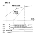
- FIG. 9F shows a waveform diagram of a request signal (request signal) output from the phase difference detection means 6.
- the magnetic sensors 3 ⁇ / b> A and 3 ⁇ / b> B output a power-on signal immediately after the power is turned on, and the power-on signal is input to the absolute angle output mode execution unit 15.
- the mode execution signal generation means 16 is a means for outputting a signal (ABS_mode signal) indicating that the absolute angle output mode execution means 15 is executing an output operation in the absolute angle output mode.
- the mode execution signal generation unit 16 is configured as a part of the absolute angle output mode execution unit 15, for example.
- FIG. 9D shows a waveform diagram of the ABS_mode signal output by the mode execution signal generation means 16.
- the magnetic sensors 3A and 3B detect the magnetic field phase and output the magnetic field phase information to the phase difference detecting means 6 (FIG. 9A to FIG. 9). (F)) and the case of rotating (FIGS. 10A to 10F) will be described separately.
- the absolute angle output request signal (see FIG. 9F) is sent from the phase difference detection means 6 to the angle information output circuit 20 in the phase detection circuits 13A and 13B of the magnetic sensors 3A and 3B.
- the absolute angle output mode execution means 15 becomes operable and indicates that the absolute angle output mode is in effect as shown in FIG. 9D from the mode execution signal generation means 16.
- ABS_mode A mode execution signal (ABS_mode) is generated, and rotation pulse signals (A, B, Z) are generated from the rotation pulse signal generation means 17 as shown in FIGS. 9 (A), (B), (C).
- ABS_mode signal is first set to 1, then the index signal (Z-phase signal) is output, and two rotation pulse signals (A-phase signal and B-phase signal) are output after a delay.
- the index signal (Z-phase signal) in this case is output regardless of the zero phase of the magnetic sensors 3A and 3B.
- the position counters 18A and 18B indicating the absolute angle values are reset to 0 by receiving the index signal (Z phase signal).
- the position counters 18A and 18B count the A-phase signal and B-phase signal output following the Z-phase signal as shown in FIG.
- the handling of the A-phase signal and the B-phase signal by the position counters 18A and 18B is performed by counting at the rising and falling edge portions of these signals (multiplication by 4).
- the rotation pulse signal generation unit 17 adds the count values in the position counters 18A and 18B as the A phase signal and the B phase signal. The number of pulses that become Qn is output.
- the absolute angle output mode is executed by inputting the absolute angle output mode request signal from the phase difference detection means 6 to the angle information output circuit 20 of the phase detection circuits 13A and 13B in the magnetic sensors 3A and 3B.
- the absolute angle output mode execution means 15 is set to the absolute angle output mode as part of the initialization operation. Is done. In this case, the power-on signal output from the magnetic sensors 3A, 3B becomes a timing signal in the absolute angle output mode instead of the request signal (request).
- phase difference detection means 6 when the power of the magnetic sensors 3A and 3B is turned on, an AB phase signal having the number of pulses corresponding to the current magnetic field phase detected by the magnetic sensors 3A and 3B is output.
- the current magnetic field phase information is transmitted to the phase difference detection means 6.
- the phase difference detection means 6 When the phase difference detection means 6 is reset or when the phase difference detection means 6 takes a long time to start and the AB phase signal immediately after power-on cannot be accurately received, the output of the magnetic phase information from the phase difference detection means 6 Is inputted to the angle information output circuit 20 of the phase detection circuits 13A and 13B in the magnetic sensors 3A and 3B again, and the absolute angle detection mode is executed again, whereby the current magnetic field phase information is changed. It becomes possible to transfer to the phase difference diameter means 6.
- the A, B, and Z phase signals are output in the form of a pulse signal as fast as possible.
- the time required to transfer the magnetic field phase information to the phase difference detection means 6 can be minimized.
- the absolute angle output is output from the phase difference detection means 6 to the angle information output circuit 20 of the phase detection circuits 13A and 13B in the magnetic sensors 3A and 3B as shown in FIG.
- the request signal (request) is input
- the absolute angle output mode execution means 15 becomes operable in response to this, and the mode execution signal generation means 16 is in the absolute angle output mode as shown in FIG.
- a mode execution signal (ABS_mode 1) indicating the existence is generated, and the rotation pulse signal (A, B, Z phase) is generated from the rotation pulse signal generation means 17 as shown in FIGS. 9 (B), (C), (D). Signal) is generated.
- the position counters 18A and 18B indicating the absolute angle value are reset by receiving the Z-phase signal, and the A-phase signal and B-phase signal output following the Z-phase signal are converted into the position counter. 18A and 18B count.
- the magnetic field phase information detected by the magnetic sensors 3A and 3B uses the ABZ-phase pulse signal similar to that of the conventional incremental encoder without adding special hardware. Then, it can be transmitted to the phase difference detecting means 6. For this reason, high-speed transmission that is resistant to noise is possible, and the number of main lines of wiring can be reduced. Also, since there is no communication protocol overhead, rotation information can be transmitted in a minimum time.
- the absolute angle output mode execution means 15 executes the output in the absolute angle output mode in response to a request signal (request) from the phase difference detection means 6 for the magnetic sensors 3A and 3B, the phase difference detection means The magnetic field phase information can be output according to the state 6 and the phase difference can be calculated with a margin.
- the absolute angle calculated by the angle calculating means 7 is divided into two A-phase and B-phase pulse signals having a phase difference of 90 degrees and a Z-phase pulse signal indicating the origin position. It may be output as an ABZ phase signal.
- an absolute angle output request signal (request) is input from the reception side circuit 44 to the angle information output circuit 10
- the absolute information in the angle information output circuit 10 is responded accordingly.
- the angle information output circuit 10 may be configured such that the A, B, and Z phase signals are output from the rotation pulse signal generation means 47 in FIG.
- a rotation pulse signal (ABZ phase signal) corresponding to the change in the absolute angle detected with the rotation of the rotating member 4 (FIG. 1) is output from the angle calculating means 7.
- the magnetic sensors 3A and 3B and the signal processing circuit including the angle information output circuit 10 shown in FIG. 7 are integrated as a sensor module 11 as shown in the example of FIG.
- the sensor module 11 may be integrated on one semiconductor chip.
- advantages such as a reduction in the number of parts, an improvement in the positional accuracy of the magnetic sensors 3A and 3B, a reduction in manufacturing costs, a reduction in assembly costs, and an improvement in detection accuracy due to signal noise reduction are obtained.
- a low-cost rotation detection device 1 can be obtained.
- the two magnetic encoders 2A and 2B are arranged close to each other.
- the rotation detection device 1 includes a plurality of magnetic encoders 2A and 2B that are provided in concentric rings and have different numbers of magnetic poles, and a plurality of magnetic sensors 3A that detect magnetic fields of the magnetic encoders 2A and 2B, respectively. , 3B, and each of these magnetic sensors 3A, 3B has a function of detecting position information in the magnetic poles of the magnetic encoders 2A, 2B. From the sensor element and the magnetic field signal detected by the sensor element, The phase detection means 13A and 13B for obtaining the phase and outputting it as an ABZ phase signal are provided. The phase difference detection means 6 obtains the phase difference of each magnetic field signal from the output of the phase detection means 13A and 13B. Since the absolute angle of the magnetic encoders 2A, 2B is calculated by the angle calculation means 7 based on the detected phase difference, it is strong against noise. It can be a rotation detecting device capable of accurately detect the absolute angle even during high-speed rotation.
- the characteristics of the typical example in the above embodiment are summarized as follows. Transmission of the detection phase signal to the phase difference detection means 6 in FIG. 7 is transmitted to FIG. 8 using an ABZ-phase pulse signal.
- the detected magnetic phase is handled as phase data of 0 to 360 degrees, and the magnetic phase data is transmitted in the form of a series of pulse outputs as shown in the chart of FIG. According to this method, since analog signal transmission is not used, it is resistant to noise.
- a rotation pulse accompanying the rotation of the rotating body is transmitted and followed by counting by the counters 18A and 18B. The detection accuracy of the absolute angle can be increased.
- phase signal detected by one of the magnetic sensors 3A (or 3B) (equivalent to the rotation pulse except in the absolute angle output mode) is output as in the pulse output shown at the top of FIG. Since a rotation signal can be output without internal delay, an angle sensor that supports high-speed rotation can be realized.
- the two magnetic encoders 2A and 2B are exemplified.
- the number of magnetic encoders is not limited to two, and three or more magnetic encoders having different numbers of magnetic pole pairs are combined. It may be configured to detect a wider range of absolute angles.
- this rotation detection device 1 is used to detect the rotation of the motor, if the combination of P and P + Pn is adjusted in accordance with the number of rotor poles Pn in the adjustment of the difference in the number of magnetic pole pairs, the rotation detection device 1 causes the motor to This is convenient for controlling the rotation of the motor.
- each of the magnetic sensors 3A and 3B has phase detection means 13A and 13B for detecting the phase in the magnetic pole, and position information output using the ABZ signal can be performed independently.
- each magnetic sensor 3A, 3B has only a multiplication function for multiplying the phase in the magnetic pole, and there may be no function for outputting a Z-phase signal for each magnetic pole.
- the phase in the magnetic pole is obtained and stored separately using two-phase analog signals (sin ⁇ , cos ⁇ ) obtained by the two magnetic sensor elements 3A1, 3A2.
- the position counters 18A and 18B are operated by integrating the output AB signals, and the angle detection can be continued.
- the position counters 18A and 18B malfunction (erroneously count) due to the influence of noise or the like, there is no opportunity to correct the error, and the detection error remains.
- At least one magnetic encoder among a plurality of magnetic encoders having different numbers of magnetic poles is formed by a plurality of tracks, and an index signal is provided at a specific position of these tracks.
- a phase shift pattern for generating the waveform is formed.
- the magnetic encoder 2A on the outer diameter side is respectively a magnetic encoder. It is formed of two tracks 2Am and 2Ai that are tracks.
- Both magnetic encoders 2A and 2B are of an axial type in which a magnetic pole pair is formed on the end surface in the axial direction of a ring-shaped magnetic member.
- the two tracks 2Am, 2Ai of the outer diameter side magnetic encoder 2A have the same number of magnetic poles, but the outer diameter side track 2Ai is the inner diameter side track.
- the magnetic pole width is partially different from the phase detection track 2Am, which is 2 Am, and becomes an index track. That is, in two tracks 2Am and 2Ai, index positions P1 for generating an index signal are determined at constant intervals in the circumferential direction, and the magnetic pole transition positions in the circumferential direction from the S pole to the N pole of the track 2Ai are the index positions. In the position P1, it has shifted
- the index positions P1 are formed at equal intervals by a number equal to the difference n in the number of magnetic pole pairs between the magnetic encoders 2A and 2B.
- the pattern ZP where the magnetic pole transition position changes in the track 2Ai with respect to the phase detection track 2Am is a “phase shift pattern” for generating an index signal.
- the magnetic sensors 3Am and 3Ai are opposed to the track 2Am and the track 2Ai, respectively, through a minute gap. Of these magnetic sensors 3Am and 3Ai, the magnetic sensor 3Ai detects the deviation of the magnetic pole transition position and outputs an index signal.
- n index signals can be output per rotation of the magnetic encoder.
- the detected index signal is output from the magnetic sensor 3Ai as a Z-phase signal.
- the phase difference detection means 6 can reset the position counter 18A to “0” by receiving this index signal. For this reason, even if the position counter 18A erroneously counts due to the influence of noise or the like, there is no effect after the position counter 18A is reset. For this reason, retention of errors can be prevented.
- the index positions P1 may be formed at regular intervals in the circumferential direction as described above, or may be formed on all the magnetic pole pairs in the plurality of tracks 2Am and 2Ai. When the index position P1 is formed in all the magnetic pole pairs, this is equivalent to a configuration in which the magnetic sensor itself can detect the phase in the magnetic pole and output the ABZ signal.
- a phase shift pattern for generating an index signal may be formed in each of the plurality of magnetic encoders 2A and 2B.
- the phase difference detecting means 6 receives both the index signals, thereby counting both AB phase signals.
- 18B can be reset to "0". Since the erroneous counts in the position counters 18A and 18B are reset, the reliability of the detected value can be further improved.
- the index positions P1 may be formed at regular intervals in the circumferential direction, or may be formed in all the magnetic pole pairs.
- the delay time may be a problem depending on the configuration.
- the processing using the index signal can be executed without waiting for the calculation of the absolute angle to end. Therefore, there is also an effect of improving the responsiveness at the time of high speed rotation.
- the phase difference detection means 6 may perform an operation of setting the position counters 18A and 18B to a prescribed value at the timing when the index signal is received.
- FIG. 13 is a cross-sectional view showing an embodiment of a bearing with a rotation detecting device in which the rotation detecting device 1 of the first or second embodiment is mounted on a bearing.
- This bearing 50 with a rotation detection device is provided at one end of a rolling bearing 51 in which a plurality of rolling elements 54 are interposed between an inner ring 52 that is a rotation side raceway and an outer ring 53 that is a stationary side raceway. Is provided.
- the rolling bearing 51 is a deep groove ball bearing, and rolling surfaces 52 a and 53 a of the rolling elements 54 are formed on the outer diameter surface of the inner ring 52 and the inner diameter surface of the outer ring 53, respectively.
- the bearing space between the inner ring 52 and the outer ring 53 is sealed with a seal 56 at the end opposite to the installation side of the rotation detection device 1.
- the two magnetic encoders 2A and 2B of the rotation detection device 1 are provided side by side in the axial direction on the outer diameter surface of a ring-shaped cored bar 57 that is press-fitted into the outer diameter surface of one end of the inner ring 52.
- the two magnetic sensors 3A and 3B of the rotation detecting device 1 are integrated as a sensor module 11 together with other signal processing circuits as shown in FIG. 2, and are inserted inside a ring-shaped metal sensor housing 58.
- the resin mold 59 is attached to the inner surface of one end of the outer ring 53 through the sensor housing 58.
- the magnetic encoders 2A and 2B and the corresponding magnetic sensors 3A and 3B are arranged to face each other in the radial direction.
- the lead wire 60 connected to the sensor module 11 passes through the sensor housing 59 and is drawn out to the outside, and exchange of signals and power supply are performed between the sensor module 11 and an external circuit via the lead wire 60.
Landscapes
- Physics & Mathematics (AREA)
- General Physics & Mathematics (AREA)
- Engineering & Computer Science (AREA)
- General Engineering & Computer Science (AREA)
- Mechanical Engineering (AREA)
- Transmission And Conversion Of Sensor Element Output (AREA)
Abstract
ノイズに強く高速回転時でも精度良く絶対角度を検出できる回転検出装置、およびこれを搭載した回転検出装置付き軸受を提供する。この回転検出装置(1)は、同心のリング状に設けられ互いに磁極数が異なる複数の磁気エンコーダ(2A,2B)と、各磁気エンコーダ(2A,2B)の磁界をそれぞれ検出する複数の磁気センサ(3A,3B)とを備える。各磁気センサ(3A,3B)は、磁気エンコーダ(2A,2B)の磁極内における位置の情報を検出する機能を有し、センサ素子と、そのセンサ素子の検出した磁界信号からその位相を求めこれをABZ相信号として出力する位相検出手段(13A,13B)とでなる。各磁気センサ(3A,3B)の検出した磁界信号の位相差を求める位相差検出手段(6)を設け、この検出した位相差に基づいて磁気エンコーダ(2A,2B)の絶対角度を算出する角度算出手段(7)を設ける。
Description
本出願は、2008年12月24日出願の特願2008-327467および2009年11月30日出願の特願2009-271042の優先権を主張するものであり、その全体を参照により本願の一部をなすものとして引用する。
この発明は、各種の機器における回転角度検出、特に各種モータの回転制御のための回転角度検出などに用いられる回転検出装置、およびその回転検出装置を搭載した回転検出装置付き軸受に関する。
この種の回転検出装置として、巻き線ステータとロータを用いた回転検出装置であって、ロータに極数の異なる複数のトラック群を形成することでアブソリュートエンコーダを構成し、トラック群から検出される信号の位相差により絶対角度を検出するようにしたものが提案されている(例えば特許文献1)。
他の回転検出装置として、2相の磁界信号を得るものが提案されている(例えば特許文献2)。これは、磁気パルスを発生する例えば周方向に磁極対を並べた磁気エンコーダなどのリング状の磁気パルス発生手段と、この磁気パルス発生手段に対してその周方向にほぼ整列させられ前記磁気パルスを検出する複数の検出素子とを備え、検出素子の出力信号を演算することにより絶対角度を検出する。
また、他の回転検出装置として、ABZ相信号を用いて絶対角度を出力するモードを実行するようにしたものも提案されている(例えば特許文献3)。
さらに、他の回転装置として、極数の異なる複列の磁気エンコーダを用い、それらの磁気エンコーダの磁界を検出できる複数の磁気センサを使用することにより、これら磁気センサが検出する磁界信号の互いの位相差から絶対角度を算出するようにしたものが提案されている(例えば特許文献4)。
しかし、いずれの提案例も、ノイズに強く、高速回転時でも精度良く絶対角度を検出できるという各利点を同時に満足できるものではない。
特許文献4では、複数の磁気センサの検出した磁気位相から絶対角度を算出する構成において、各々の検出した磁気位相信号を位相差検出回路に伝達するための信号形態についての説明がない。特に、複数の磁気センサが別々の素子として実装される場合、高精度な絶対角度検出を行うためには、検出した磁界信号の位相を、ノイズで乱されることなく、少ない配線で正確に伝達することが、絶対角度検出には必要である。特許文献4には、このような各々の磁気センサが検出した磁界信号の位相を位相差検出回路に伝達する信号形態について開示がない。
特許文献4では、複数の磁気センサの検出した磁気位相から絶対角度を算出する構成において、各々の検出した磁気位相信号を位相差検出回路に伝達するための信号形態についての説明がない。特に、複数の磁気センサが別々の素子として実装される場合、高精度な絶対角度検出を行うためには、検出した磁界信号の位相を、ノイズで乱されることなく、少ない配線で正確に伝達することが、絶対角度検出には必要である。特許文献4には、このような各々の磁気センサが検出した磁界信号の位相を位相差検出回路に伝達する信号形態について開示がない。
上記した磁界信号の位相の伝達にシリアル通信方法を使用することは可能であるが、シリアル通信ではデータの伝送に時間がかかるため遅延が発生し、高速回転時の検出精度が悪化するという問題がある。
この発明の目的は、ノイズに強く高速回転時でも精度良く絶対角度を検出できる回転検出装置、およびこの回転検出装置を搭載した回転検出装置付き軸受を提供することである。
この発明の回転検出装置は、同心のリング状に設けられ互いに磁極数が異なる複数の磁気エンコーダと、これら各磁気エンコーダの磁界をそれぞれ検出する複数の磁気センサとを備え、前記各磁気センサは磁気エンコーダの磁極内における位置の情報を検出する機能を有したものである回転検出装置であって、前記各磁気センサは、複数のセンサ素子と、そのセンサ素子の検出した磁界信号からその位相を求めこれを互いに90°位相の異なるA相およびB相のパルス信号A,Bおよび原点位置を示すZ相のパルス信号Zを含むABZ相信号として出力する位相検出手段とを有するものとし、この位相検出手段の出力から前記各磁界信号の位相差を求める位相差検出手段と、この検出した位相差に基づいて磁気エンコーダの絶対角度を算出する角度算出手段とを設けている。前記複数の磁気センサは、個別にパッケージされた形態で配線基板や他の手段に実装され、前記位相差検出手段と、配線基板の配線または独立した配線で接続されていても良い。
この構成によると、各磁気センサの検出した磁界信号の位相をアナログ信号でなくABZ相信号として位相差検出手段に伝送する。そのため、ノイズに強く高速な伝達が可能で、配線の本線も少なくて済む。特に、前記複数の磁気センサが別々の素子としてに実装されている場合に、磁気センサから前記位相差検出手段への磁界信号の伝送に、ノイズに強く高速な伝達が可能という利点がより効果的に発揮される。また、シリアル通信と異なり、通信プロトコルのオーバーヘッドがないため、回転情報を最小時間で伝送することができる。その結果、ノイズに強く高速回転時でも精度良く絶対角度を検出できる回転検出装置とすることができる。
この構成によると、各磁気センサの検出した磁界信号の位相をアナログ信号でなくABZ相信号として位相差検出手段に伝送する。そのため、ノイズに強く高速な伝達が可能で、配線の本線も少なくて済む。特に、前記複数の磁気センサが別々の素子としてに実装されている場合に、磁気センサから前記位相差検出手段への磁界信号の伝送に、ノイズに強く高速な伝達が可能という利点がより効果的に発揮される。また、シリアル通信と異なり、通信プロトコルのオーバーヘッドがないため、回転情報を最小時間で伝送することができる。その結果、ノイズに強く高速回転時でも精度良く絶対角度を検出できる回転検出装置とすることができる。
この発明において、磁極数が異なる複数の磁気エンコーダのうち、少なくとも一方の磁気エンコーダが複数のトラックで形成され、これらトラックの特定の位置にインデックス信号を生成するための位相ずれパターンが形成されていても良い。この場合、磁気センサは、位相ずれを検出してインデックス信号をZ相信号として出力する。位相差検出手段は、このインデックス信号を受信することで、A相信号およびB相信号を計数するカウンタをリセットまたは規定値に設定することができる。このため、ノイズ等の影響で誤カウントした場合であっても、リセット以降または規定値に設定以降は影響が及ばない。このため、誤差の滞留を防止できる。
この発明において、前記インデックス信号を生成するための位相ずれパターンが、磁気エンコーダ間の磁極対数の差nと等しい個数だけ等間隔に形成され、前記磁気エンコーダの1回転あたりにn個(nは自然数)のZ相信号を出力するように構成されたものであっても良い。
前記インデックス信号を生成するための位相ずれパターンが、複数のトラックにおける全ての磁極対に形成され、磁極対毎にZ相信号を出力するように構成されたものであっても良い。この場合、磁気センサそのものが磁極内位相を検出してABZ信号を出力できる構成と等価になる。
前記インデックス信号を生成するための位相ずれパターンが、複数のトラックにおける全ての磁極対に形成され、磁極対毎にZ相信号を出力するように構成されたものであっても良い。この場合、磁気センサそのものが磁極内位相を検出してABZ信号を出力できる構成と等価になる。
この発明において、前記位相検出手段は、前記磁界信号の位相を絶対角度で出力する絶対角度出力モードと、上記A相およびB相のパルス信号A,Bのみを出力するモードとに切換えて出力可能な絶対角度出力モード実行手段を有するものとしても良い。このようにモード切換可能とすることで、その出力される信号の処理の簡易化、出力信号の使用の多様化が図れる。
この発明において、前記位相検出手段の出力するABZ相信号のうち、少なくとも1組の信号を、この回転検出装置に対する外部に出力するABZ相信号外部出力手段を設けても良い。
この構成の場合、ABZ相信号外部出力手段により外部に出力されたABZ相信号を用いて回転速度などの検出を行うことができる。
この構成の場合、ABZ相信号外部出力手段により外部に出力されたABZ相信号を用いて回転速度などの検出を行うことができる。
この発明において、前記磁気センサが、互いに磁極ピッチ内でずれた位置に配置された複数のセンサ素子を有し、sin およびcos の2相の信号出力を得られるものであって、磁極内における位置を、前記出力信号を用いた内挿演算処理で検出するものであっても良い。例えば、前記複数のセンサ素子は2個であって、互いに、前記磁極ピッチで90°離れた位置に配置して良い。
磁気センサをこのような構成とすると、磁気エンコーダの磁界分布をオン・オフ信号としてではなく、アナログ電圧による正弦波状の信号としてより細かく検出でき、精度の良い絶対角度検出が可能となる。
磁気センサをこのような構成とすると、磁気エンコーダの磁界分布をオン・オフ信号としてではなく、アナログ電圧による正弦波状の信号としてより細かく検出でき、精度の良い絶対角度検出が可能となる。
この発明において、前記磁気センサが、磁気エンコーダの磁極の並び方向に沿ってセンサ素子が並ぶラインセンサを有し、sin ,cos の2相の信号出力を演算によって生成して、磁極内における位置を、前記出力信号を用いた内挿演算処理で検出するものであっても良い。
磁気センサのセンサ素子をこのようにラインセンサで構成した場合、磁界パターンの歪みやノイズの影響が低減されて、より高い精度で磁気エンコーダの位相を検出することが可能である。
磁気センサのセンサ素子をこのようにラインセンサで構成した場合、磁界パターンの歪みやノイズの影響が低減されて、より高い精度で磁気エンコーダの位相を検出することが可能である。
この発明において、前記角度算出手段で算出された絶対角度情報をABZ相信号として出力する角度情報出力手段を設けても良い。この構成の場合、絶対角度を出力するインタフェース手段を別途備える必要がなく、回転検出装置の回路構成、および回転検出装置が搭載される機器側の回路構成を簡略化することができる。
この発明において、前記磁気エンコーダは、ラジアルタイプであっても、アキシアルタイプであっても良い。すなわち、前記磁気エンコーダが外周面に各磁極を有し、前記磁気センサの前記磁気センサ素子が、磁気エンコーダに対してラジアル方向に対面するものであっても良い。また、前記磁気エンコーダが軸方向面に各磁極を有し、前記磁気センサの前記磁気センサ素子が、磁気エンコーダに対してアキシアル方向に対面するものであっても良い。
この発明の回転検出装置付き軸受は、この発明の上記いずれかの構成の回転検出装置を軸受に搭載したものである。
この構成によると、軸受使用機器の部品点数、組立工数の削減、およびコンパクト化が図れる。
この構成によると、軸受使用機器の部品点数、組立工数の削減、およびコンパクト化が図れる。
この発明は、添付の図面を参考にした以下の好適な実施形態の説明から、より明瞭に理解されるであろう。しかしながら、実施形態および図面は単なる図示および説明のためのものであり、この発明の範囲を定めるために利用されるべきものではない。この発明の範囲は添付の請求の範囲によって定まる。添付図面において、複数の図面における同一の符号は、同一または相当する部分を示す。
この発明の第1実施形態にかかる回転検出装置の一構成例の概略図である。
同回転検出装置の他の構成例の要部側面図である。
磁気センサの一構成例の説明図である。
磁気センサの他の構成例の説明図である。
磁気センサの検出信号および位相差検出手段の検出信号の波形図である。
各磁気センサの検出信号の位相と両検出信号の位相差を示す波形図である。
この回転検出装置の絶対角度検出回路の一構成例を示すブロック図である。
この回転検出装置における磁気センサでの角度情報出力回路の一構成例を示すブロック図である。
回転部材停止時の磁気センサにおける角度情報出力回路の絶対角度出力モードでの出力動作を説明する波形図である。
回転部材回転時の磁気センサにおける角度情報出力回路の絶対角度出力モードでの出力動作を説明する波形図である。
この回転検出装置の角度情報出力回路の一構成例を示すブロック図である。
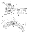
(A)は、この発明の第2実施形態にかかる回転検出装置の一構成例を示すブロック図、(B)は同回転検出装置の磁気エンコーダの正面図である。
この回転検出装置を軸受に搭載した回転検出装置付き軸受の一実施形態を示す断面図である。
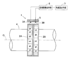
この発明の第1実施形態を図1ないし図13と共に説明する。図1は、この実施形態の回転検出装置の概略構成を示す。この回転検出装置1は、例えばモータの回転軸などの回転部材4の外周に、その軸心Oに対して同心のリング状に設けられた複数(ここでは2つ)の磁気エンコーダ2A,2Bと、これら各磁気エンコーダ2A,2Bの磁界をそれぞれ検出する複数(ここでは2つ)の磁気センサ3A,3Bとを備える。磁気センサ3A,3Bは、図1の例では前記各磁気エンコーダ2A,2Bに対して微小のギャップを介してそれぞれ径方向(ラジアル方向)に対向するように、例えばモータのハウジング等の固定部材5に設けられる。ここでは、磁気センサ3Aが磁気エンコーダ2Aに対向し、磁気センサ3Bが磁気エンコーダ2Bに対向する。
磁気エンコーダ2A,2Bは、複数の磁極対(磁極Sと磁極Nの1組)を周方向に等ピッチで着磁させたリング状の磁性部材であり、ラジアルタイプである図1の例では、その外周面に磁極対が着磁されている。これら2つの磁気エンコーダ2A,2Bの磁極対の数は互いに異ならせてある。また、図1の例では、2つの磁気エンコーダ2A,2Bを軸方向に隣接させて配置しているが、これら磁気エンコーダ2A,2Bが同一の回転をするならば、それぞれを別の場所に配置しても良い。
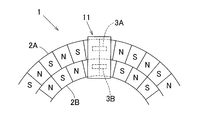
磁気エンコーダ2A,2Bの他の例として、図2に示すように、リング状の磁性部材の軸方向端面に複数の磁極対を周方向に等ピッチで並ぶように着磁させたアキシアルタイプのものを用いても良い。この例では、2つの磁気エンコーダ2A,2Bを、内外周に隣接するように同心に配置している。アキシアルタイプの磁気エンコーダ2A,2Bの場合、その着磁面に対向する軸方向に向けて各磁気センサ3A,3Bが配置される。
なお、複数の磁気エンコーダ2A,2Bは、ラジアルタイプおよびアキシアルタイプのいずれにおいても、必ずしも隣接して配置されていなくても良く、一体に回転可能であれば、互いに離れて配置されていても良い。
なお、複数の磁気エンコーダ2A,2Bは、ラジアルタイプおよびアキシアルタイプのいずれにおいても、必ずしも隣接して配置されていなくても良く、一体に回転可能であれば、互いに離れて配置されていても良い。
磁気センサ3A,3Bは、対応する磁気エンコーダ2A,2Bの磁極対の数よりも高い分解能で磁極検出できる機能、つまり磁気エンコーダ2A,2Bの磁極の範囲内における位置の情報を検出する機能を有するものとされる。この機能を満たすために、例えば磁気センサ3Aのセンサ素子として、対応する磁気エンコーダ2Aの1磁極対のピッチλを1周期とするとき、図3のように90度位相差(λ/4)となるように磁極の並び方向に離して配置したホール素子などの2つの磁気センサ素子3A1,3A2を用いたものとしても良い。この場合、これら2つの磁気センサ素子3A1,3A2により得られる2相の信号(sinφ,cosφ)を周波数逓倍したうえで、磁極内位相(ファイ=tan-1(sinφ/cosφ))を算出するものとする。すなわち、磁極内位相を内挿演算処理で算出するものとする。他の磁気センサ3Bについても、上記磁気センサ3Aと同様である。なお図3の波形図は、磁気エンコーダ2Aの磁極の配列を磁界強度に換算して示したものである。
磁気センサ3A,3Bのセンサ素子をこのような構成とすると、磁気エンコーダ2A,2Bの磁界分布をオン・オフ信号としてではなく、アナログ電圧による正弦波状の信号としてより細かく検出でき、精度の良い絶対角度検出が可能となる。
磁気エンコーダ2A,2Bの磁極の範囲内における位置の情報を検出する機能を有する磁気センサ3A,3Bのセンサ素子の他の例として、図4(B)に示すようなラインセンサを用いても良い。すなわち、例えば磁気センサ3Aのセンサ素子として、対応する磁気エンコーダ2Aの磁極の並び方向に沿って磁気センサ素子3aが並ぶラインセンサ3AA,3ABを用いる。なお、図4(A)は、磁気エンコーダ2Aにおける1磁極の区間を磁界強度に換算して波形図で示したものである。この場合、磁気センサ3Aの第1のラインセンサ3AAは、図4(A)における180度の位相区間のうち90度の位相区間に対応付けて配置し、第2のラインセンサ3ABは残りの90度の位相区間に対応付けて配置する。このような配置構成により、第1のラインセンサ3AAの検出信号を加算回路31で加算した信号S1と、第2のラインセンサ3ABの検出信号を加算回路32で加算した信号S2を別の加算回路33で加算することで、図4(C)に示すような磁界信号に応じたsin 信号を得る。また、信号S1と、インバータ35を介した信号S2をさらに別の加算回路34で加算することで、図4(C)に示すような磁界信号に応じたcos 信号を得る。このようにして得られた2相の出力信号から、磁極の範囲内における位置を検出する。
磁気センサ3A,3Bのセンサ素子をこのようにラインセンサで構成した場合、磁界パターンの歪みやノイズの影響が低減されて、より高い精度で磁気エンコーダ2A,2Bの位相を検出することが可能である。
各磁気センサ3A,3Bは、図7に示すように、磁気センサ素子3A1,3A2,3B1,3B2のほかに、磁気センサ素子の検出した磁界信号からそれらの位相を求め、この求めた位相をABZ相信号として出力する位相検出回路13A,13Bを有する。ABZ相信号は、互いに90°位相の異なるA相およびB相のパルス信号A,B、および原点位置を示すZ相のパルス信号Zを含む信号である。図7では、センサ素子の例として、図3の構成例の磁気センサ素子3A1,3A2,3B1,3B2の場合を示している。
例えば、図1の構成例において、磁気センサ3A,3Bは位相差検出手段6に接続される。位相差検出手段6は、各磁気センサ3A,3Bの検出した磁界信号の位相差を求める手段であり、その後段に角度算出手段7が接続される。角度算出手段7は、位相差検出手段6の検出した位相差に基づいて磁気エンコーダ2A,2Bの絶対角度を算出する手段である。
上記複数の磁気センサ3A,3Bは、別々の素子として、つまり個別にパッケージされた形態で設けられて配線基板(図示せず)や他の手段に実装され、前記位相差検出手段6と、配線基板の配線または独立した配線で接続されている。
上記複数の磁気センサ3A,3Bは、別々の素子として、つまり個別にパッケージされた形態で設けられて配線基板(図示せず)や他の手段に実装され、前記位相差検出手段6と、配線基板の配線または独立した配線で接続されている。
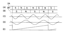
この回転検出装置1による絶対角度検出の概略動作を、図5(A)~(E)および図6(A)~(E)を参照して以下に説明する。図1において、2つの磁気エンコーダ2B,2Aの磁極対の数をPとP+nとすると、両磁気エンコーダ2A,2Bの間では1回転あたり磁極対にしてn個分の位相差があるので、これら磁気エンコーダ2A,2Bに対応する磁気センサ3A,3Bの検出信号の位相は、360/n度回転するごとに一致する。
図5(A),(B)には両磁気エンコーダ2A,2Bの磁極のパターン例を示し、図5(C),(D)にはこれら磁気エンコーダに対応する磁気センサ3A,3Bの検出信号の波形を示す。この場合、磁気エンコーダ2Aの3磁極対に対して、磁気エンコーダ2Bの2磁極対が対応しており、この区間内での絶対位置を検出することができる。図5(E)は、図5(C),(D)の検出信号に基づき、図1の位相差検出手段6より求められる位相差の出力信号の波形図を示す。
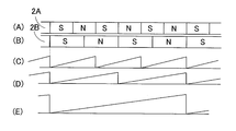
なお、図6(A)~(E)は、各磁気センサ3A,3Bによる検出位相と位相差の波形図を示す。すなわち、図6(A),(B)には両磁気エンコーダ2A,2Bの磁極のパターン例を示し、図6(C),(D)には対応する磁気センサ3A,3Bの検出位相の波形図を示し、図6(E)には位相差検出手段6より出力される位相差信号の波形図を示す。
なお、図6(A)~(E)は、各磁気センサ3A,3Bによる検出位相と位相差の波形図を示す。すなわち、図6(A),(B)には両磁気エンコーダ2A,2Bの磁極のパターン例を示し、図6(C),(D)には対応する磁気センサ3A,3Bの検出位相の波形図を示し、図6(E)には位相差検出手段6より出力される位相差信号の波形図を示す。
図7は、この回転検出装置1における絶対角度検出回路の構成例を示す。図5(C),(D)に示したような各磁気センサ3A,3Bの磁気センサ素子3A1,3A2,3B1,3B2による検出信号に基づき、それぞれ対応する位相検出回路13A,13Bは、図6(C),(D)に示したような検出位相信号を出力する。ここでは、説明を簡単にするために検出位相信号を鋸歯の波形として示しているが、後述するように位相検出回路13A,13Bは検出位相信号としてABZ相信号(ABZ1,ABZ2)を出力する。位相差検出手段6は、これらの検出位相信号に基づき、図6(E)に示したような位相差信号を出力する。その次段に設けられた角度算出手段7は、位相差検出手段6で求められた位相差を、予め設定された計算パラメータにしたがって絶対角度へ換算する処理を行う。角度算出手段7で用いられる計算パラメータは不揮発メモリなどのメモリ8に記憶されている。このメモリ8には、前記計算パラメータのほか、磁気エンコーダ2A,2Bの磁極対の数の設定、絶対角度基準位置、信号出力の方法など、装置の動作に必要な情報が記憶されている。ここでは、メモリ8の次段に通信インタフェース(I/F)9を設けることで、通信インタフェース9を通じてメモリ8の内容を更新できる構成とされている。これにより、個別の設定情報を使用状況に応じて可変設定でき、使い勝手が良くなる。
角度算出手段7で算出された絶対角度情報は、パラレル信号、シリアルデータ、アナログ電圧、PWMなどの変調信号として、角度情報出力回路10から、あるいは前記通信I/F9を介して出力される。また、角度算出手段7からは回転パルス信号も出力される。回転パルス信号としては、2つの磁気センサ3A,3Bの検出信号のうち、いずれか1つの信号を出力すれば良い。上記したように、各磁気センサ3A,3Bはそれぞれ逓倍機能を備えているので、高い分解能で回転信号を出力することができる。
図8にブロック図で示すように、各磁気センサ3A,3Bの位相検出回路13A,13Bは、センサ素子の検出した磁界信号からそれらの位相を算出する角度算出手段12のほか、算出した位相情報をABZ相信号として出力し位相差検出手段6に伝達する角度情報出力回路20を有する。
前記各磁気センサ3A,3Bの位相検出回路13A,13Bの出力するABZ相信号のうち、少なくとも1組の信号(ここでは位相検出回路13Aの出力するABZ相信号ABZ1)は、ABZ相信号外部出力手段14によって外部に出力される。このABZ相信号外部出力手段14は、位相検出回路13Aの出力から外部に引き出される別の信号回路として構成される。
このように、後段の位相差検出手段6などを経ずに位相検出回路13Aから外部にABZ相信号を出力させると、このABZ相信号を回転部材4の回転速度検出などにそのまま利用することができる。
このように、後段の位相差検出手段6などを経ずに位相検出回路13Aから外部にABZ相信号を出力させると、このABZ相信号を回転部材4の回転速度検出などにそのまま利用することができる。
角度情報出力手段20は、回転パルス信号生成手段17と、絶対角度出力モード実行手段15と、モード実行信号生成手段16とを有する。
回転パルス信号生成手段17は、前記角度算出手段12で算出した磁気位相に基づきABZ相信号を生成する手段である。図9(A),(B)には、回転パルス信号生成手段17が生成する2つのパルス信号(A相信号,B相信号)の波形図を示す。図9(C)には、回転パルス信号生成手段17が生成するZ相信号の波形図を示す。
回転パルス信号生成手段17は、前記角度算出手段12で算出した磁気位相に基づきABZ相信号を生成する手段である。図9(A),(B)には、回転パルス信号生成手段17が生成する2つのパルス信号(A相信号,B相信号)の波形図を示す。図9(C)には、回転パルス信号生成手段17が生成するZ相信号の波形図を示す。
絶対角度出力モード実行手段15は、前記回転パルス信号(AB相信号)を、前記インデックス信号(Z相信号)を出力してから現在の磁界位相まで出力するモードである絶対角度出力モードと、上記A相およびB相のパルス信号A,Bのみを出力するモードとに切換えて出力可能な手段である。前記回転パルス信号生成手段17により生成される回転パルス信号(AB相信号)は、前記絶対角度出力モードの場合とそのモードでない場合とで異なる。すなわち、絶対角度出力モードでない場合(通常時)の回転パルス信号(AB相信号)は、磁気センサ3A,3Bが検出する磁界位相の変化に応じた速度のパルス信号として生成される。これに対して、絶対角度出力モードでの回転パルス信号(AB相信号)は、前記通常時のパルス信号に比べて十分高速なパルス信号として生成される。なお、インデックス信号(Z相信号)も、絶対角度出力モードでは高速なパルス信号とされる。
絶対角度出力モード実行手段15は、磁気センサ3A,3Bの電源オンの直後、および磁気センサ3A,3Bの出力を受ける位相差検出手段6からの要求信号(request信号)に応じて前記絶対角度出力モードの出力動作を実行する。図9(F)には、位相差検出手段6から出力される要求信号(request信号) の波形図を示す。磁気センサ3A,3Bは、電源オンの直後に電源オン信号を出力し、この電源オン信号が絶対角度出力モード実行手段15に入力される。
絶対角度出力モード実行手段15は、磁気センサ3A,3Bの電源オンの直後、および磁気センサ3A,3Bの出力を受ける位相差検出手段6からの要求信号(request信号)に応じて前記絶対角度出力モードの出力動作を実行する。図9(F)には、位相差検出手段6から出力される要求信号(request信号) の波形図を示す。磁気センサ3A,3Bは、電源オンの直後に電源オン信号を出力し、この電源オン信号が絶対角度出力モード実行手段15に入力される。
モード実行信号生成手段16は、前記絶対角度出力モード実行手段15が絶対角度出力モードの出力動作を実行していることを示す信号(ABS_mode信号)を出力する手段である。なお、モード実行信号生成手段16は、例えば、絶対角度出力モード実行手段15の一部として構成される。図9(D)には、モード実行信号生成手段16が出力するABS_mode信号の波形図を示す。
次に、前記各磁気センサ3A,3Bが磁界位相を検出し、その磁界位相情報を位相差検出手段6に向けて出力する動作を、回転部材が停止している場合(図9(A)~(F))と回転している場合(図10(A)~(F))とに分けて説明する。
・回転部材が停止している場合
位相差検出手段6から磁気センサ3A,3Bの位相検出回路13A,13Bにおける角度情報出力回路20に、図9(F)のように絶対角度出力の要求信号(request)が入力されると、これに呼応して絶対角度出力モード実行手段15が動作可能となり、モード実行信号生成手段16から図9(D)のように絶対角度出力モード中であることを示すモード実行信号(ABS_mode)が生成され、回転パルス信号生成手段17から図9(A),(B),(C)のように各回転パルス信号(A,B,Z)が生成される。各信号の生成順序としては、先ずABS_mode信号が1となり、その後インデックス信号(Z相信号)が出力され、さらに遅れて2つの回転パルス信号(A相信号,B相信号)が出力される。この場合のインデックス信号(Z相信号)は、磁気センサ3A,3Bの零相とは無関係に出力される。
・回転部材が停止している場合
位相差検出手段6から磁気センサ3A,3Bの位相検出回路13A,13Bにおける角度情報出力回路20に、図9(F)のように絶対角度出力の要求信号(request)が入力されると、これに呼応して絶対角度出力モード実行手段15が動作可能となり、モード実行信号生成手段16から図9(D)のように絶対角度出力モード中であることを示すモード実行信号(ABS_mode)が生成され、回転パルス信号生成手段17から図9(A),(B),(C)のように各回転パルス信号(A,B,Z)が生成される。各信号の生成順序としては、先ずABS_mode信号が1となり、その後インデックス信号(Z相信号)が出力され、さらに遅れて2つの回転パルス信号(A相信号,B相信号)が出力される。この場合のインデックス信号(Z相信号)は、磁気センサ3A,3Bの零相とは無関係に出力される。
これらの信号を受信して動作する位相差検出手段6では、インデックス信号(Z相信号)を受信することで絶対角度値を示すポジションカウンタ18A,18Bが0にリセットされる。Z相信号に続いて出力されるA相信号およびB相信号を、前記ポジションカウンタ18A,18Bが図9(E)のように計数する。A相信号およびB相信号のポジションカウンタ18A,18Bでの扱いは、これら各信号の立ち上がりおよび立ち下がりのエッジ部で計数するもの(4逓倍)とされる。磁気センサ3A,3Bが検出している現在の磁界位相の絶対値をQnとすると、回転パルス信号生成手段17からは、A相信号およびB相信号としてポジションカウンタ18A,18Bでの計数値が合計Qnとなるパルス数が出力される。
また、回転パルス信号生成手段17が、A相信号およびB相信号として合計Qnカウント分のパルス数を出力すると、モード実行信号生成手段16の生成するABS_mode信号が0となり、絶対角度出力モードが終了する。その結果、位相差検出手段6のポジションカウンタ18A,18Bの計数値は、絶対角度出力モードが終了すると、磁気センサ3A,3Bが検出している現在の磁界位相の絶対値Qnを示す。
したがって、絶対角度出力モード動作中(ABS_mode=1)に回転パルス信号生成手段17から出力されるA相信号およびB相信号を計数することにより、位相差検出手段6のポジションカウンタ18A,18Bに絶対位相データQnが転送されることになり、別途シリアル通信手段を設けることなく、ABZ相信号を用いて磁界位相情報を位相差検出手段6に向けて出力することができる。
また、回転パルス信号生成手段17が、A相信号およびB相信号として合計Qnカウント分のパルス数を出力すると、モード実行信号生成手段16の生成するABS_mode信号が0となり、絶対角度出力モードが終了する。その結果、位相差検出手段6のポジションカウンタ18A,18Bの計数値は、絶対角度出力モードが終了すると、磁気センサ3A,3Bが検出している現在の磁界位相の絶対値Qnを示す。
したがって、絶対角度出力モード動作中(ABS_mode=1)に回転パルス信号生成手段17から出力されるA相信号およびB相信号を計数することにより、位相差検出手段6のポジションカウンタ18A,18Bに絶対位相データQnが転送されることになり、別途シリアル通信手段を設けることなく、ABZ相信号を用いて磁界位相情報を位相差検出手段6に向けて出力することができる。
上記説明では、位相差検出手段6から絶対角度出力モードの要求信号(request)を磁気センサ3A,3Bにおける位相検出回路13A,13Bの角度情報出力回路20に入力することによって、絶対角度出力モード実行手段15を絶対角度出力モードとする場合を示したが、磁気センサ3A,3Bが電源オンとなったときにも、初期化動作の一部として絶対角度出力モード実行手段15が絶対角度出力モードとされる。この場合、磁気センサ3A,3Bから出力される電源オン信号が前記要求信号(request)に代わって、絶対角度出力モードのタイミング信号となる。
この場合にも、磁気センサ3A,3Bの電源がオンになると、磁気センサ3A,3Bの検出する現在の磁界位相に相当するパルス数のAB相信号が出力されるため、この信号を受信する位相差検出手段6に現在の磁界位相情報が伝えられることになる。位相差検出手段6がリセットされた場合や、位相差検出手段6の起動時間が長くかかり電源オン直後のAB相信号を正確に受信できない場合には、位相差検出手段6から磁界位相情報の出力を要求する要求信号(request)を改めて磁気センサ3A,3Bにおける位相検出回路13A,13Bの角度情報出力回路20に入力し、再度絶対角度検出モードを実行させることにより、現在の磁界位相情報を位相差径手段6に転送することが可能になる。
この場合にも、磁気センサ3A,3Bの電源がオンになると、磁気センサ3A,3Bの検出する現在の磁界位相に相当するパルス数のAB相信号が出力されるため、この信号を受信する位相差検出手段6に現在の磁界位相情報が伝えられることになる。位相差検出手段6がリセットされた場合や、位相差検出手段6の起動時間が長くかかり電源オン直後のAB相信号を正確に受信できない場合には、位相差検出手段6から磁界位相情報の出力を要求する要求信号(request)を改めて磁気センサ3A,3Bにおける位相検出回路13A,13Bの角度情報出力回路20に入力し、再度絶対角度検出モードを実行させることにより、現在の磁界位相情報を位相差径手段6に転送することが可能になる。
なお、絶対角度出力モードにおいては、上記したようにA,B,Zの各相信号はできるかぎり高速なパルス信号の形態で出力される。その結果、磁界位相情報を位相差検出手段6に転送するために必要な時間を最低限にすることができる。
・回転部材が回転している場合
この場合も、位相差検出手段6から磁気センサ3A,3Bにおける位相検出回路13A,13Bの角度情報出力回路20に、図10(F)のように絶対角度出力の要求信号(request)が入力されると、これに呼応して絶対角度出力モード実行手段15が動作可能となり、モード実行信号生成手段16から図10(E)のように絶対角度出力モード中であることを示すモード実行信号(ABS_mode=1)が生成され、回転パルス信号生成手段17から図9(B),(C),(D)のように各回転パルス信号(A,B,Z相信号)が生成される。
位相差検出手段6では、Z相信号を受信することで絶対角度値を示すポジションカウンタ18A,18Bがリセットされ、Z相信号に続いて出力されるA相信号およびB相信号を、前記ポジションカウンタ18A,18Bが計数する。A相信号およびB相信号のパルス出力が、図10(A)のように一旦現在の磁界位相に達すると、そこで絶対角度出力モード動作が終了する(ABS_mode=0)。その後は、回転部材の回転に伴い磁気センサ3A,3Bで検出される磁界位相の変化に応じた回転パルス信号(ABZ相信号)が出力される。これにより、パルスを計数することで各磁気センサ3A,3Bの検出する磁界位相を知る位相差検出手段6では、絶対角度出力モード動作が終了(ABS_mode=0)となった後は実際の磁界位相情報を常に取得している状態となる。
この場合も、位相差検出手段6から磁気センサ3A,3Bにおける位相検出回路13A,13Bの角度情報出力回路20に、図10(F)のように絶対角度出力の要求信号(request)が入力されると、これに呼応して絶対角度出力モード実行手段15が動作可能となり、モード実行信号生成手段16から図10(E)のように絶対角度出力モード中であることを示すモード実行信号(ABS_mode=1)が生成され、回転パルス信号生成手段17から図9(B),(C),(D)のように各回転パルス信号(A,B,Z相信号)が生成される。
位相差検出手段6では、Z相信号を受信することで絶対角度値を示すポジションカウンタ18A,18Bがリセットされ、Z相信号に続いて出力されるA相信号およびB相信号を、前記ポジションカウンタ18A,18Bが計数する。A相信号およびB相信号のパルス出力が、図10(A)のように一旦現在の磁界位相に達すると、そこで絶対角度出力モード動作が終了する(ABS_mode=0)。その後は、回転部材の回転に伴い磁気センサ3A,3Bで検出される磁界位相の変化に応じた回転パルス信号(ABZ相信号)が出力される。これにより、パルスを計数することで各磁気センサ3A,3Bの検出する磁界位相を知る位相差検出手段6では、絶対角度出力モード動作が終了(ABS_mode=0)となった後は実際の磁界位相情報を常に取得している状態となる。
このように、この実施形態の回転検出装置1では、磁気センサ3A,3Bで検出した磁界位相情報を、特別なハードウェアの追加なしに、従来のインクリメンタル・エンコーダと同様なABZ相パルス信号を利用して位相差検出手段6に伝達することができる。このため、ノイズに強く高速な伝達が可能で、配線の本線も少なくて済む。また、通信プロトコルのオーバーヘッドがないため、回転情報を最小時間で伝送することができる。
また、磁気センサ3A,3Bにおける位相検出回路13A,13Bの角度情報出力回路20の絶対角度出力モード実行手段15が絶対角度出力モードを実行していることを示す信号(ABS_mode)を出力するモード実行信号生成手段16を設けているので、絶対角度出力モード動作中を示す信号線を備えておれば、位相差検出手段6において、磁気センサ3A,3Bから送信されてくる回転パルス信号(ABZ相信号)がどのような状態で出力されているかを判別することができ、機器の制御状態などを乱すことなく磁界位相情報を伝達することもできる。
また、磁気センサ3A,3Bに対する位相差検出手段6からの要求信号(request)に応じて、絶対角度出力モード実行手段15が絶対角度出力モードによる出力を実行するものとしているので、位相差検出手段6の状態に応じて磁界位相情報を出力することができ、位相差の演算を余裕を持って行うことができる。
図7の角度情報出力回路10でも、前記角度算出手段7で算出された絶対角度を、互いに90度位相の異なるA相およびB相の2つのパルス信号と、原点位置を示すZ相のパルス信号とでなるABZ相信号として出力するようにしても良い。
この場合、図11に示すように、受信側回路44から角度情報出力回路10に対して絶対角度出力の要求信号(request)が入力されると、これに呼応して角度情報出力回路10における絶対角度出力モード実行手段45が動作可能となり、角度情報出力回路10におけるモード実行信号生成手段46から絶対角度出力モード中であることを示すモード実行信号(ABS_mode=1)が生成され、角度情報出力回路10における回転パルス信号生成手段47からA,B,Z相信号が出力されるように、角度情報出力回路10を構成しても良い。
受信側回路44では、Z相信号を受信することで絶対角度値を示すポジションカウンタ48が0にリセットされ、Z相信号に続いて出力されるA相信号およびB相信号を、前記ポジションカウンタ48が計数する。A相信号およびB相信号のパルス出力が、一旦現在の絶対角度値に達すると、そこで絶対角度出力モード動作が終了する(ABS_mode=0)。その後は、回転部材4(図1)の回転に伴い検出される絶対角度の変化に応じた回転パルス信号(ABZ相信号)を角度算出手段7から出力する。これにより、パルスを計数することで絶対角度を知る受信側回路44では、絶対角度出力モード動作が終了(ABS_mode=0)となった後は実際の絶対角度情報を常に取得している状態となる。
この場合、図11に示すように、受信側回路44から角度情報出力回路10に対して絶対角度出力の要求信号(request)が入力されると、これに呼応して角度情報出力回路10における絶対角度出力モード実行手段45が動作可能となり、角度情報出力回路10におけるモード実行信号生成手段46から絶対角度出力モード中であることを示すモード実行信号(ABS_mode=1)が生成され、角度情報出力回路10における回転パルス信号生成手段47からA,B,Z相信号が出力されるように、角度情報出力回路10を構成しても良い。
受信側回路44では、Z相信号を受信することで絶対角度値を示すポジションカウンタ48が0にリセットされ、Z相信号に続いて出力されるA相信号およびB相信号を、前記ポジションカウンタ48が計数する。A相信号およびB相信号のパルス出力が、一旦現在の絶対角度値に達すると、そこで絶対角度出力モード動作が終了する(ABS_mode=0)。その後は、回転部材4(図1)の回転に伴い検出される絶対角度の変化に応じた回転パルス信号(ABZ相信号)を角度算出手段7から出力する。これにより、パルスを計数することで絶対角度を知る受信側回路44では、絶対角度出力モード動作が終了(ABS_mode=0)となった後は実際の絶対角度情報を常に取得している状態となる。
このように、角度情報出力回路10からABZ相信号のような回転パルス信号を出力し、絶対角度出力モードによって絶対角度情報を出力する構成とすると、絶対角度を出力するインタフェースを別途備える必要がなく、この回転検出装置1の回路構成、および回転検出装置1が搭載される機器側の回路構成を簡略化することができる。
また、この回転検出装置1において、前記磁気センサ3A,3Bと、図7に示した角度情報出力回路10を含む信号処理回路とを、例えば図2の例で示すように、センサモジュール11として一体化しても良いし、このセンサモジュール11を1つの半導体チップに集積しても良い。このように構成した場合、部品点数の低減、磁気センサ3A,3Bの互いの位置精度の向上、製造コストの低減、組立コストの低減、信号ノイズ低減による検出精度向上などのメリットが得られ、小型で低コストの回転検出装置1とすることができる。
なお、この場合、2つの磁気エンコーダ2A,2Bに対して1つのセンサモジュール11を対向させることになるので、2つの磁気エンコーダ2A,2Bは互いに近接して配置させることになる。
なお、この場合、2つの磁気エンコーダ2A,2Bに対して1つのセンサモジュール11を対向させることになるので、2つの磁気エンコーダ2A,2Bは互いに近接して配置させることになる。
このように、この回転検出装置1は、同心のリング状に設けられ互いに磁極数が異なる複数の磁気エンコーダ2A,2Bと、これら各磁気エンコーダ2A,2Bの磁界をそれぞれ検出する複数の磁気センサ3A,3Bとを備え、これら各磁気センサ3A,3Bは磁気エンコーダ2A,2Bの磁極内における位置の情報を検出する機能を有したものであり、センサ素子と、そのセンサ素子の検出した磁界信号からその位相を求めこれをABZ相信号として出力する位相検出手段13A,13Bとを有するものとし、この位相検出手段13A,13B出力から前記各磁界信号の位相差を位相差検出手段6で求め、この検出した位相差に基づいて磁気エンコーダ2A,2Bの絶対角度を角度算出手段7で算出するようにしているので、ノイズに強く高速回転時でも精度良く絶対角度を検出できる回転検出装置とすることができる。
上記実施形態における典型例の特徴を整理すると、次のとおりである。図7の位相差検出手段6への検出位相信号の伝達は、ABZ相のパルス信号を用いて図8に伝達される。
検出した磁気位相を0~360度の位相データとして扱い、図10に示すチャートのように磁気位相データを一連のパルス出力の形態で伝達する。この方式によれば、アナログ信号伝達を用いないためノイズに強い。また、電源ON直後に位相データを絶対角度出力モードで出力後は、回転体の回転にともなう回転パルスが伝達され、カウンタ18A,18Bによる計数で追従するため、高速な応答が可能で、算出される絶対角度の検出精度を高めることができる。シリアル通信によるデータ伝送と比較して、回転情報の伝達に遅延がないため、高速回転での応答性を向上させることができる。
また、図7の最上部に示したパルス出力のように、一方の磁気センサ3A(または3B)の検出した位相信号(絶対角度出力モード以外は回転パルスと等価)を出力すれば、角度計算による内部遅延なく回転信号を出力できるため、高速回転にも対応した角度センサが実現できる。
検出した磁気位相を0~360度の位相データとして扱い、図10に示すチャートのように磁気位相データを一連のパルス出力の形態で伝達する。この方式によれば、アナログ信号伝達を用いないためノイズに強い。また、電源ON直後に位相データを絶対角度出力モードで出力後は、回転体の回転にともなう回転パルスが伝達され、カウンタ18A,18Bによる計数で追従するため、高速な応答が可能で、算出される絶対角度の検出精度を高めることができる。シリアル通信によるデータ伝送と比較して、回転情報の伝達に遅延がないため、高速回転での応答性を向上させることができる。
また、図7の最上部に示したパルス出力のように、一方の磁気センサ3A(または3B)の検出した位相信号(絶対角度出力モード以外は回転パルスと等価)を出力すれば、角度計算による内部遅延なく回転信号を出力できるため、高速回転にも対応した角度センサが実現できる。
このように、次の各利点が得られる。
・位相信号の伝達にアナログ信号を用いないため、ノイズに強い。
・電源ON直後に、各センサ3A,3Bの検出した磁気位相を絶対角度出力モードで出力するため、余分な配線を用意することなく磁気位相のデータを伝送することができる。
・一旦絶対角度(位相)データを出力した後は、回転に応じたABZ信号を出力するため、検出位相信号を高速に伝達可能で、検出遅れもほとんど発生せず、高精度な絶対角度検出が可能。
・位相信号の伝達にアナログ信号を用いないため、ノイズに強い。
・電源ON直後に、各センサ3A,3Bの検出した磁気位相を絶対角度出力モードで出力するため、余分な配線を用意することなく磁気位相のデータを伝送することができる。
・一旦絶対角度(位相)データを出力した後は、回転に応じたABZ信号を出力するため、検出位相信号を高速に伝達可能で、検出遅れもほとんど発生せず、高精度な絶対角度検出が可能。
なお、上記実施形態では、2つの磁気エンコーダ2A,2Bを用いたものを例示したが、磁気エンコーダは2つでなくてもよく、磁極対の数の異なる3つ以上の磁気エンコーダを組み合わせて、より広い範囲の絶対角度を検出する構成としても良い。この回転検出装置1をモータの回転検出に使用する場合、上記磁極対の数の差の調整において、モータのロータ極数Pnに合わせてPとP+Pnという組合せとすれば、回転検出装置1によりモータの電気角を検出できるため、モータの回転制御に好都合である。
前記図7の構成では、各磁気センサ3A,3Bが磁極内位相を検出する位相検出手段13A,13Bを有し、単独でABZ信号を用いた位置情報出力が可能としていた。しかし、各磁気センサ3A,3Bが、磁極内位相を逓倍する逓倍機能だけを備えており、磁極毎にZ相信号を出力する機能がない場合もある。
その場合、例えば、2つの磁気センサ素子3A1,3A2により得られる2相のアナログ信号(sinφ,cosφ)等を別途利用して磁極内位相を求めて記憶する。その後、出力されるAB信号の積算によりポジションカウンタ18A,18Bを動作させ、角度検出を継続することができる。
しかし、ノイズ等の影響でポジションカウンタ18A,18Bが誤動作(誤カウント)することがあると、その誤差を修正する機会がなく、検出誤差が滞留してしまう。
その場合、例えば、2つの磁気センサ素子3A1,3A2により得られる2相のアナログ信号(sinφ,cosφ)等を別途利用して磁極内位相を求めて記憶する。その後、出力されるAB信号の積算によりポジションカウンタ18A,18Bを動作させ、角度検出を継続することができる。
しかし、ノイズ等の影響でポジションカウンタ18A,18Bが誤動作(誤カウント)することがあると、その誤差を修正する機会がなく、検出誤差が滞留してしまう。
そこで、この発明の第2実施形態に係る回転検出装置1では、磁極数が異なる複数の磁気エンコーダのうち、少なくとも一方の磁気エンコーダを複数のトラックで形成し、これらトラックの特定の位置にインデックス信号を生成するための位相ずれパターンを形成している。具体的には、図12(B)の3トラック構成の例に示すように、互いに同心で磁極数が異なる2つの磁気エンコーダ2A,2Bのうち、外径側の磁気エンコーダ2Aが、それぞれ磁気エンコーダトラックである2つのトラック2Am,2Aiで形成されている。両磁気エンコーダ2A,2Bは、リング状の磁性部材の軸方向端面に磁極対を形成したアキシアルタイプである。
図12(B)に示すように、外径側の磁気エンコーダ2Aの2つのトラック2Am,2Aiは、互いに磁極数が同じであるが、このうちの外径側のトラック2Aiは、内径側のトラック2Amである位相検出用のトラック2Amに対し部分的に磁極幅が異なっていて、インデックストラックとなる。すなわち2つのトラック2Amおよびトラック2Aiにおいて、インデックス信号を生成するインデックス位置P1が、円周方向一定間隔で定められ、前記トラック2AiのS極からN極への周方向の磁極遷移位置が、前記インデックス位置P1では周方向一方側(左側)にずれている。このインデックス位置P1は、例えば、磁気エンコーダ2A,2B間の磁極対数の差nと等しい個数だけ等間隔に形成される。
トラック2Aiにおける、位相検出用のトラック2Amに対して前記の磁極遷移位置が変わる部分のパターンZPが、インデックス信号を生成するための「位相ずれパターン」となる。
磁気センサ3Am,3Aiは、トラック2Am、トラック2Aiにそれぞれ微小のギャップを介して対向する。これら磁気センサ3Am,3Aiのうち磁気センサ3Aiは、前記磁極遷移位置のずれを検出してインデックス信号を出力する。インデックス位置P1がn個等間隔に形成される場合、磁気エンコーダ1回転あたりn個のインデックス信号を出力し得る。
トラック2Aiにおける、位相検出用のトラック2Amに対して前記の磁極遷移位置が変わる部分のパターンZPが、インデックス信号を生成するための「位相ずれパターン」となる。
磁気センサ3Am,3Aiは、トラック2Am、トラック2Aiにそれぞれ微小のギャップを介して対向する。これら磁気センサ3Am,3Aiのうち磁気センサ3Aiは、前記磁極遷移位置のずれを検出してインデックス信号を出力する。インデックス位置P1がn個等間隔に形成される場合、磁気エンコーダ1回転あたりn個のインデックス信号を出力し得る。
図12(A)に示すように、検出した前記インデックス信号をZ相信号として、前記磁気センサ3Aiから出力する。位相差検出手段6は、このインデックス信号を受信することで、ポジションカウンタ18Aを「0」にリセットすることができる。このため、ノイズ等の影響でポジションカウンタ18Aが誤カウントした場合であっても、ポジションカウンタ18Aのリセット以降は影響が及ばない。このため、誤差の滞留を防止できる。
前記インデックス位置P1は、前記のように円周方向一定間隔で形成されても良いし、複数のトラック2Am,2Aiにおける全ての磁極対に形成されていても良い。インデックス位置P1が全ての磁極対に形成された場合、磁気センサそのものが磁極内位相を検出してABZ信号を出力できる構成と等価になる。
前記インデックス位置P1は、前記のように円周方向一定間隔で形成されても良いし、複数のトラック2Am,2Aiにおける全ての磁極対に形成されていても良い。インデックス位置P1が全ての磁極対に形成された場合、磁気センサそのものが磁極内位相を検出してABZ信号を出力できる構成と等価になる。
複数の磁気エンコーダ2A,2Bそれぞれに、インデックス信号を生成するための位相ずれパターンが形成されていても良い。磁極数の異なる磁気エンコーダ2A,2Bの両方がインデックス信号を備えていた場合、位相差検出手段6は、前記両方のインデックス信号を受信することで、両方のAB相信号を計数するポジションカウンタ18A,18Bを「0」にリセットすることができる。ポジションカウンタ18A,18Bにおける誤カウントがそれぞれリセットされるため、検出値に対する信頼性をさらに向上させることができる。この場合においても、インデックス位置P1は円周方向一定間隔で形成されても良いし、全ての磁極対に形成されていても良い。
また、回転体の高速回転時に、磁極数の異なる両方の磁気エンコーダ2A,2Bの信号から絶対角度を計算すると、構成によっては遅延時間が問題となる場合がある。しかし、インデックス信号が一定位置で出力されていれば、絶対角度の計算が終わるのを待たずに、前記インデックス信号を用いた処理を実行することも可能になる。よって、高速回転時における応答性を高める効果もある。
位相差検出手段6は、前記インデックス信号を受信したタイミングでポジションカウンタ18A,18Bを規定の値に設定する動作を行うようにしても良い。
また、回転体の高速回転時に、磁極数の異なる両方の磁気エンコーダ2A,2Bの信号から絶対角度を計算すると、構成によっては遅延時間が問題となる場合がある。しかし、インデックス信号が一定位置で出力されていれば、絶対角度の計算が終わるのを待たずに、前記インデックス信号を用いた処理を実行することも可能になる。よって、高速回転時における応答性を高める効果もある。
位相差検出手段6は、前記インデックス信号を受信したタイミングでポジションカウンタ18A,18Bを規定の値に設定する動作を行うようにしても良い。
図13は、上記第1または第2実施形態のいずれかの回転検出装置1を軸受に搭載した回転検出装置付き軸受の一実施形態を示す断面図である。この回転検出装置付き軸受50は、回転側軌道輪である内輪52と固定側軌道輪である外輪53の間に複数の転動体54が介在する転がり軸受51の一端部に、上記回転検出装置1を設けたものである。転がり軸受51は深溝玉軸受からなり、内輪52の外径面および外輪53の内径面にはそれぞれ転動体54の転走面52a,53aが形成されている。内輪52と外輪53の間の軸受空間は、回転検出装置1の設置側とは反対側の端部がシール56で密封されている。
回転検出装置1の2つの磁気エンコーダ2A,2Bは、内輪52の一端部の外径面に圧入嵌合されるリング状の芯金57の外径面に、軸方向に並べて設けられる。回転検出装置1の2つの磁気センサ3A,3Bは、図2で示したように他の信号処理回路と共にセンサモジュール11として一体化され、リング状の金属製センサハウジング58の内側に挿入された状態で樹脂モールド59され、センサハウジング58を介して外輪53の一端部の内径面に取付けられる。これにより、磁気エンコーダ2A,2Bと対応する磁気センサ3A,3Bとがラジアル方向に対向配置される。センサモジュール11に接続されるリード線60はセンサハウジング59を貫通して外部に引き出され、このリード線60を介してセンサモジュール11と外部回路との間で信号の授受や電源供給が行われる。
この回転検出装置付き軸受50では、上記回転検出装置1を転がり軸受51に搭載しているので、軸受使用機器の部品点数、組立工数の削減、およびコンパクト化を図ることができる。
以上のとおり、図面を参照しながら好適な実施形態を説明したが、当業者であれば、本件明細書を見て、自明な範囲内で種々の変更および修正を容易に想定するであろう。したがって、そのような変更および修正は、請求の範囲から定まるこの発明の範囲内のものと解釈される。
1…回転検出装置
2A,2B…磁気エンコーダ
3A,3B…磁気センサ
3A1,3A2,3B1,3B2…磁気センサ素子
3AA,3AB…ラインセンサ
6…位相差検出手段
7…角度算出手段
10…角度情報出力回路
13A,13B…位相検出回路
50…回転検出装置付き軸受
51…転がり軸受
2A,2B…磁気エンコーダ
3A,3B…磁気センサ
3A1,3A2,3B1,3B2…磁気センサ素子
3AA,3AB…ラインセンサ
6…位相差検出手段
7…角度算出手段
10…角度情報出力回路
13A,13B…位相検出回路
50…回転検出装置付き軸受
51…転がり軸受
Claims (14)
- 同心のリング状に設けられ互いに磁極数が異なる複数の磁気エンコーダと、これら各磁気エンコーダの磁界をそれぞれ検出する複数の磁気センサとを備え、前記各磁気センサは磁気エンコーダの磁極内における位置の情報を検出する機能を有したものである回転検出装置であって、
前記各磁気センサは、複数のセンサ素子と、そのセンサ素子の検出した磁界信号からその位相を求めこれを互いに90°位相の異なるA相およびB相のパルス信号A,Bおよび原点位置を示すZ相のパルス信号Zを含むABZ相信号として出力する位相検出手段とを有するものとし、この位相検出手段の出力から前記各磁界信号の位相差を求める位相差検出手段と、この検出した位相差に基づいて磁気エンコーダの絶対角度を算出する角度算出手段とを設けた回転検出装置。 - 請求項1において、磁極数が異なる複数の磁気エンコーダのうち、少なくとも一方の磁気エンコーダが複数のトラックで形成され、これらトラックの特定の位置にインデックス信号を生成するための位相ずれパターンが形成されている回転検出装置。
- 請求項2において、前記インデックス信号を生成するための位相ずれパターンが、磁気エンコーダ間の磁極対数の差nと等しい個数だけ等間隔に形成され、前記磁気エンコーダの1回転あたりにn個(nは自然数)のZ相信号を出力するように構成された回転検出装置。
- 請求項2において、前記インデックス信号を生成するための位相ずれパターンが、複数のトラックにおける全ての磁極対に形成され、磁極対毎にZ相信号を出力するように構成された回転検出装置。
- 請求項1において、前記複数の磁気センサが個別にパッケージされた形態で実装され、前記位相差検出手段と配線で接続されている回転検出装置。
- 請求項1において、前記位相検出手段は、前記磁界信号の位相を絶対角度で出力する絶対角度出力モードと、上記A相およびB相のパルス信号A,Bのみを出力するモードとに切換えて出力可能な絶対角度出力モード実行手段を有する回転検出装置。
- 請求項1において、前記位相検出手段の出力するABZ相信号のうち、少なくとも1組の信号を、この回転検出装置に対する外部に出力するABZ相信号外部出力手段を設けた回転検出装置。
- 請求項1において、前記磁気センサが、互いに磁極ピッチ内でずれた位置に配置された複数のセンサ素子を有し、sin およびcos の2相の信号出力を得られるものであって、磁極内における位置を、前記出力信号を用いた内挿演算処理で検出するものである回転検出装置。
- 請求項8において、前記複数のセンサ素子は2個であって、互いに、前記磁極ピッチで90°離れた位置に配置されている回転検出装置。
- 請求項1において、前記磁気センサが、磁気エンコーダの磁極の並び方向に沿ってセンサ素子が並ぶラインセンサを有し、sin ,cos の2相の信号出力を演算によって生成して、磁極内における位置を、前記出力信号を用いた内挿演算処理で検出するものである回転検出装置。
- 請求項1において、前記角度算出手段で算出された絶対角度情報をABZ相信号として出力する角度情報出力手段を設けた回転検出装置。
- 請求項1において、前記磁気エンコーダが外周面に各磁極を有し、前記磁気センサの前記磁気センサ素子が、磁気エンコーダに対してラジアル方向に対面する回転検出装置。
- 請求項1において、前記磁気エンコーダが軸方向面に各磁極を有し、前記磁気センサの前記磁気センサ素子が、磁気エンコーダに対してアキシアル方向に対面する回転検出装置。
- 請求項1に記載の回転検出装置を軸受に組み込んだ回転検出装置付き軸受。
Priority Applications (2)
| Application Number | Priority Date | Filing Date | Title |
|---|---|---|---|
| EP09834415.3A EP2372313B1 (en) | 2008-12-24 | 2009-12-22 | Rotation detecting device and bearing having rotation detecting device |
| US12/998,963 US8803510B2 (en) | 2008-12-24 | 2009-12-22 | Rotation detecting device and bearing having rotation detecting device |
Applications Claiming Priority (4)
| Application Number | Priority Date | Filing Date | Title |
|---|---|---|---|
| JP2008327467 | 2008-12-24 | ||
| JP2008-327467 | 2008-12-24 | ||
| JP2009271042A JP5221494B2 (ja) | 2008-12-24 | 2009-11-30 | 回転検出装置および回転検出装置付き軸受 |
| JP2009-271042 | 2009-11-30 |
Publications (1)
| Publication Number | Publication Date |
|---|---|
| WO2010073607A1 true WO2010073607A1 (ja) | 2010-07-01 |
Family
ID=42287254
Family Applications (1)
| Application Number | Title | Priority Date | Filing Date |
|---|---|---|---|
| PCT/JP2009/007100 Ceased WO2010073607A1 (ja) | 2008-12-24 | 2009-12-22 | 回転検出装置および回転検出装置付き軸受 |
Country Status (4)
| Country | Link |
|---|---|
| US (1) | US8803510B2 (ja) |
| EP (1) | EP2372313B1 (ja) |
| JP (1) | JP5221494B2 (ja) |
| WO (1) | WO2010073607A1 (ja) |
Cited By (1)
| Publication number | Priority date | Publication date | Assignee | Title |
|---|---|---|---|---|
| CN103134525A (zh) * | 2011-12-02 | 2013-06-05 | 发那科株式会社 | 磁性编码器 |
Families Citing this family (34)
| Publication number | Priority date | Publication date | Assignee | Title |
|---|---|---|---|---|
| DE102009028093A1 (de) * | 2009-07-29 | 2011-02-10 | Robert Bosch Gmbh | Verfahren zur Herstellung eines magnetischen Sensorelements |
| US9163926B2 (en) | 2012-01-25 | 2015-10-20 | Mitutoyo Corporation | Inductive detection type rotary encoder |
| EP2672285B1 (en) * | 2012-06-06 | 2014-05-21 | Nxp B.V. | Magnetic sensor arrangement |
| JP6086205B2 (ja) * | 2012-12-12 | 2017-03-01 | 株式会社ジェイテクト | 位相差検出装置およびそれを備えた回転角検出装置 |
| CN104254760B (zh) * | 2013-04-24 | 2016-08-17 | 三菱电机株式会社 | 伺服电动机以及编码器 |
| KR101468323B1 (ko) * | 2013-07-26 | 2014-12-02 | 성균관대학교산학협력단 | 디지털 pll을 이용한 마그네틱 엔코더의 출력 신호 보상 장치 및 방법 |
| JP6165541B2 (ja) * | 2013-07-26 | 2017-07-19 | Ntn株式会社 | 回転検出装置および回転検出装置付き軸受 |
| US20160258783A1 (en) * | 2013-11-05 | 2016-09-08 | Renishaw Plc | Position measurement encoder calibration |
| US10222234B2 (en) * | 2014-06-17 | 2019-03-05 | Infineon Technologies Ag | Rotation sensor |
| US11125768B2 (en) | 2014-06-17 | 2021-09-21 | Infineon Technologies Ag | Angle based speed sensor device |
| SG10201403879WA (en) * | 2014-07-04 | 2016-02-26 | Rockwell Automation Asia Pacific Business Ctr Pte Ltd | System And Method For Incremental Encoder Loss Detection |
| FR3023370B1 (fr) | 2014-07-07 | 2016-08-19 | Ntn-Snr Roulements | Montage d’un systeme de determination de position angulaire sur un organe tournant |
| FR3028612B1 (fr) | 2014-11-17 | 2016-12-30 | Ntn-Snr Roulements | Systeme de determination de la position absolue d’un organe |
| CN107155392B (zh) * | 2015-01-09 | 2020-08-07 | 株式会社日立产机系统 | 电力转换装置和电力转换装置的控制方法 |
| JP2016217783A (ja) * | 2015-05-15 | 2016-12-22 | 日本電産サンキョー株式会社 | 位置検出装置 |
| TWI601939B (zh) * | 2016-03-04 | 2017-10-11 | 國立清華大學 | 絕對位置偵測裝置及方法 |
| US11448524B2 (en) * | 2016-04-07 | 2022-09-20 | Phoenix America Inc. | Multipole magnet for use with a pitched magnetic sensor |
| GB2552386B (en) * | 2016-07-22 | 2022-06-08 | Cmr Surgical Ltd | Magnetic position sensor mounting arrangement |
| GB2552478B (en) * | 2016-07-22 | 2021-04-28 | Cmr Surgical Ltd | Magnetic position sensor |
| KR101963106B1 (ko) * | 2016-11-29 | 2019-04-01 | 주식회사 해치텍 | 회전각 검출 장치 |
| JP6877170B2 (ja) * | 2017-02-14 | 2021-05-26 | 日本電産サンキョー株式会社 | ロータリエンコーダ及びその絶対角度位置検出方法 |
| JP6877168B2 (ja) * | 2017-02-14 | 2021-05-26 | 日本電産サンキョー株式会社 | ロータリエンコーダ及びその絶対角度位置検出方法 |
| CN110494716B (zh) * | 2017-04-13 | 2022-04-15 | 索尼公司 | 位置检测装置和位置检测方法 |
| FR3069319B1 (fr) | 2017-07-18 | 2020-10-23 | Ntn Snr Roulements | Systeme de determination de la position d'un organe |
| JP7006110B2 (ja) * | 2017-10-06 | 2022-01-24 | 日本精工株式会社 | モータ制御装置及びモータシステム |
| JP7193635B2 (ja) | 2018-12-06 | 2022-12-20 | 株式会社ハーモニック・ドライブ・システムズ | デュアルアブソリュートエンコーダ |
| US10866122B2 (en) | 2019-01-23 | 2020-12-15 | Allegro Microsystems, Llc | Magnetic field sensor for detecting an absolute position of a target object |
| US10816366B2 (en) * | 2019-01-23 | 2020-10-27 | Allegro Microsystems, Llc | Magnetic field sensor for detecting an absolute position of a target object |
| JP6779333B2 (ja) * | 2019-04-16 | 2020-11-04 | 三菱電機株式会社 | 回転角度検出装置 |
| JP7353992B2 (ja) | 2020-01-14 | 2023-10-02 | 株式会社ミツトヨ | ロータリエンコーダ |
| US11346688B2 (en) | 2020-07-06 | 2022-05-31 | Allegro Microsystems, Llc | Magnetic field sensors for detecting absolute position of multi-track targets |
| US11637482B2 (en) * | 2020-10-08 | 2023-04-25 | Analog Devices International Unlimited Company | Magnetic sensor system for motor control |
| KR102591233B1 (ko) * | 2021-02-25 | 2023-10-20 | 에스티엠(주) | 마그네틱 엔코더 |
| US12455178B2 (en) | 2023-12-22 | 2025-10-28 | Allegro Microsystems, Llc | Inductive linear stroke sensor using dual tracks with different periodicity |
Citations (6)
| Publication number | Priority date | Publication date | Assignee | Title |
|---|---|---|---|---|
| JP2002541485A (ja) | 1999-04-14 | 2002-12-03 | エス.エヌ.エール.ルールマン | コーダから生ずる磁気パルスを検出するための整列された複数の検知要素を有する素子を備えた軸受要素 |
| JP2006322927A (ja) | 2005-04-19 | 2006-11-30 | Mitsutoyo Corp | アブソリュートロータリエンコーダ及びマイクロメータ |
| JP2008039744A (ja) * | 2006-08-10 | 2008-02-21 | Uchiyama Mfg Corp | 環状磁気エンコーダ |
| JP2008116291A (ja) | 2006-11-02 | 2008-05-22 | Ntn Corp | 回転検出装置および回転検出装置付き軸受 |
| JP2008233069A (ja) | 2007-02-23 | 2008-10-02 | Ntn Corp | 回転検出装置および回転検出装置付き軸受 |
| JP2009271042A (ja) | 2008-05-07 | 2009-11-19 | Etsuo Ban | 連続波hf帯磁気共鳴装置検出器用プローブ |
Family Cites Families (8)
| Publication number | Priority date | Publication date | Assignee | Title |
|---|---|---|---|---|
| JPH0658766A (ja) * | 1992-08-05 | 1994-03-04 | Hitachi Ltd | 絶対位置検出装置およびモ−タ制御装置 |
| DE19800774B4 (de) * | 1998-01-12 | 2006-12-21 | Siemens Ag | Verfahren und magnetische Maßverkörperung zur Generierung eines Referenzsignals sowie Herstellungsverfahren für eine solche magnetische Maßverkörperung |
| JP3551252B2 (ja) * | 1998-07-23 | 2004-08-04 | 株式会社安川電機 | アブソリュートエンコーダ |
| DE10041089A1 (de) * | 2000-08-22 | 2002-03-07 | Bosch Gmbh Robert | Verfahren zur Korrektur einer Winkelmessung |
| JP2003270062A (ja) * | 2002-03-13 | 2003-09-25 | Koyo Seiko Co Ltd | 回転角度検出装置、トルク検出装置及び舵取装置 |
| JP2003269475A (ja) * | 2002-03-15 | 2003-09-25 | Ntn Corp | 原点検出可能回転センサ付軸受 |
| JP4703968B2 (ja) * | 2004-03-30 | 2011-06-15 | Ntn株式会社 | 回転センサ付軸受およびその回転センサの被検出部着磁方法 |
| CN100420914C (zh) * | 2005-04-19 | 2008-09-24 | 三丰株式会社 | 绝对式旋转编码器和千分尺 |
-
2009
- 2009-11-30 JP JP2009271042A patent/JP5221494B2/ja not_active Expired - Fee Related
- 2009-12-22 WO PCT/JP2009/007100 patent/WO2010073607A1/ja not_active Ceased
- 2009-12-22 EP EP09834415.3A patent/EP2372313B1/en not_active Not-in-force
- 2009-12-22 US US12/998,963 patent/US8803510B2/en not_active Expired - Fee Related
Patent Citations (6)
| Publication number | Priority date | Publication date | Assignee | Title |
|---|---|---|---|---|
| JP2002541485A (ja) | 1999-04-14 | 2002-12-03 | エス.エヌ.エール.ルールマン | コーダから生ずる磁気パルスを検出するための整列された複数の検知要素を有する素子を備えた軸受要素 |
| JP2006322927A (ja) | 2005-04-19 | 2006-11-30 | Mitsutoyo Corp | アブソリュートロータリエンコーダ及びマイクロメータ |
| JP2008039744A (ja) * | 2006-08-10 | 2008-02-21 | Uchiyama Mfg Corp | 環状磁気エンコーダ |
| JP2008116291A (ja) | 2006-11-02 | 2008-05-22 | Ntn Corp | 回転検出装置および回転検出装置付き軸受 |
| JP2008233069A (ja) | 2007-02-23 | 2008-10-02 | Ntn Corp | 回転検出装置および回転検出装置付き軸受 |
| JP2009271042A (ja) | 2008-05-07 | 2009-11-19 | Etsuo Ban | 連続波hf帯磁気共鳴装置検出器用プローブ |
Cited By (3)
| Publication number | Priority date | Publication date | Assignee | Title |
|---|---|---|---|---|
| CN103134525A (zh) * | 2011-12-02 | 2013-06-05 | 发那科株式会社 | 磁性编码器 |
| CN105737865A (zh) * | 2011-12-02 | 2016-07-06 | 发那科株式会社 | 磁性编码器 |
| CN105737865B (zh) * | 2011-12-02 | 2018-09-11 | 发那科株式会社 | 磁性编码器 |
Also Published As
| Publication number | Publication date |
|---|---|
| EP2372313A1 (en) | 2011-10-05 |
| US8803510B2 (en) | 2014-08-12 |
| EP2372313B1 (en) | 2019-08-07 |
| JP2010169664A (ja) | 2010-08-05 |
| EP2372313A4 (en) | 2017-07-05 |
| US20110309824A1 (en) | 2011-12-22 |
| JP5221494B2 (ja) | 2013-06-26 |
Similar Documents
| Publication | Publication Date | Title |
|---|---|---|
| JP5221494B2 (ja) | 回転検出装置および回転検出装置付き軸受 | |
| JP5583317B2 (ja) | 回転検出装置および回転検出装置付き軸受 | |
| JP5081553B2 (ja) | 回転検出装置および回転検出装置付き軸受 | |
| JP6477933B2 (ja) | 回転角度検出装置及び回転角度検出方法 | |
| TWI579533B (zh) | Absolute encoder devices and motors | |
| US7301333B2 (en) | Angle position detection apparatus | |
| US20210310834A1 (en) | Dual absolute encoder | |
| US9303972B2 (en) | Position-measuring device and method for operating the same | |
| CN101529209B (zh) | 旋转检测装置和带有旋转检测装置的轴承 | |
| US10312839B2 (en) | Brushless DC motor with control electronics motor assembly | |
| US7023203B2 (en) | Absolute magnetic encoder | |
| JP2008267868A (ja) | 回転検出装置および回転検出装置付き軸受 | |
| WO2010029742A1 (ja) | 回転検出装置および回転検出装置付き軸受 | |
| JP2009069092A (ja) | 回転検出装置および回転検出装置付き軸受 | |
| JP2012088276A (ja) | 回転検出器 | |
| US9134143B2 (en) | Absolute position detector with abnormality detection function | |
| JP2001183169A (ja) | 位置検出装置 | |
| JP2008267867A (ja) | 回転検出装置および回転検出装置付き軸受 | |
| JP5161010B2 (ja) | 回転検出装置および回転検出装置付き軸受 | |
| CN117200627A (zh) | 高精度闭环伺服系统 | |
| CN117097083A (zh) | 电机及输出轴绝对位置的检测方法 | |
| JP6201910B2 (ja) | 回転検出センサ及びその製造方法 | |
| CN117394609B (zh) | 永磁同步伺服电机及电气设备 | |
| JP2019071712A (ja) | モータ制御装置及びモータシステム | |
| CN117040206B (zh) | 高精度伺服电机及电气设备 |
Legal Events
| Date | Code | Title | Description |
|---|---|---|---|
| 121 | Ep: the epo has been informed by wipo that ep was designated in this application |
Ref document number: 09834415 Country of ref document: EP Kind code of ref document: A1 |
|
| NENP | Non-entry into the national phase |
Ref country code: DE |
|
| WWE | Wipo information: entry into national phase |
Ref document number: 2009834415 Country of ref document: EP |
|
| WWE | Wipo information: entry into national phase |
Ref document number: 12998963 Country of ref document: US |