WO2010073646A1 - カテーテル - Google Patents
カテーテル Download PDFInfo
- Publication number
- WO2010073646A1 WO2010073646A1 PCT/JP2009/007158 JP2009007158W WO2010073646A1 WO 2010073646 A1 WO2010073646 A1 WO 2010073646A1 JP 2009007158 W JP2009007158 W JP 2009007158W WO 2010073646 A1 WO2010073646 A1 WO 2010073646A1
- Authority
- WO
- WIPO (PCT)
- Prior art keywords
- catheter
- distal end
- operation line
- end portion
- bent
- Prior art date
- Legal status (The legal status is an assumption and is not a legal conclusion. Google has not performed a legal analysis and makes no representation as to the accuracy of the status listed.)
- Ceased
Links
Images


Classifications
-
- A—HUMAN NECESSITIES
- A61—MEDICAL OR VETERINARY SCIENCE; HYGIENE
- A61M—DEVICES FOR INTRODUCING MEDIA INTO, OR ONTO, THE BODY; DEVICES FOR TRANSDUCING BODY MEDIA OR FOR TAKING MEDIA FROM THE BODY; DEVICES FOR PRODUCING OR ENDING SLEEP OR STUPOR
- A61M25/00—Catheters; Hollow probes
- A61M25/01—Introducing, guiding, advancing, emplacing or holding catheters
- A61M25/0105—Steering means as part of the catheter or advancing means; Markers for positioning
- A61M25/0133—Tip steering devices
- A61M25/0147—Tip steering devices with movable mechanical means, e.g. pull wires
-
- A—HUMAN NECESSITIES
- A61—MEDICAL OR VETERINARY SCIENCE; HYGIENE
- A61B—DIAGNOSIS; SURGERY; IDENTIFICATION
- A61B1/00—Instruments for performing medical examinations of the interior of cavities or tubes of the body by visual or photographical inspection, e.g. endoscopes; Illuminating arrangements therefor
- A61B1/005—Flexible endoscopes
- A61B1/0051—Flexible endoscopes with controlled bending of insertion part
- A61B1/0057—Constructional details of force transmission elements, e.g. control wires
-
- A—HUMAN NECESSITIES
- A61—MEDICAL OR VETERINARY SCIENCE; HYGIENE
- A61M—DEVICES FOR INTRODUCING MEDIA INTO, OR ONTO, THE BODY; DEVICES FOR TRANSDUCING BODY MEDIA OR FOR TAKING MEDIA FROM THE BODY; DEVICES FOR PRODUCING OR ENDING SLEEP OR STUPOR
- A61M25/00—Catheters; Hollow probes
- A61M25/01—Introducing, guiding, advancing, emplacing or holding catheters
- A61M25/0105—Steering means as part of the catheter or advancing means; Markers for positioning
- A61M25/0133—Tip steering devices
- A61M25/0141—Tip steering devices having flexible regions as a result of using materials with different mechanical properties
-
- A—HUMAN NECESSITIES
- A61—MEDICAL OR VETERINARY SCIENCE; HYGIENE
- A61M—DEVICES FOR INTRODUCING MEDIA INTO, OR ONTO, THE BODY; DEVICES FOR TRANSDUCING BODY MEDIA OR FOR TAKING MEDIA FROM THE BODY; DEVICES FOR PRODUCING OR ENDING SLEEP OR STUPOR
- A61M25/00—Catheters; Hollow probes
- A61M25/01—Introducing, guiding, advancing, emplacing or holding catheters
- A61M25/0105—Steering means as part of the catheter or advancing means; Markers for positioning
- A61M25/0133—Tip steering devices
- A61M2025/0161—Tip steering devices wherein the distal tips have two or more deflection regions
-
- A—HUMAN NECESSITIES
- A61—MEDICAL OR VETERINARY SCIENCE; HYGIENE
- A61M—DEVICES FOR INTRODUCING MEDIA INTO, OR ONTO, THE BODY; DEVICES FOR TRANSDUCING BODY MEDIA OR FOR TAKING MEDIA FROM THE BODY; DEVICES FOR PRODUCING OR ENDING SLEEP OR STUPOR
- A61M25/00—Catheters; Hollow probes
- A61M25/0043—Catheters; Hollow probes characterised by structural features
- A61M25/005—Catheters; Hollow probes characterised by structural features with embedded materials for reinforcement, e.g. wires, coils, braids
- A61M25/0053—Catheters; Hollow probes characterised by structural features with embedded materials for reinforcement, e.g. wires, coils, braids having a variable stiffness along the longitudinal axis, e.g. by varying the pitch of the coil or braid
-
- A—HUMAN NECESSITIES
- A61—MEDICAL OR VETERINARY SCIENCE; HYGIENE
- A61M—DEVICES FOR INTRODUCING MEDIA INTO, OR ONTO, THE BODY; DEVICES FOR TRANSDUCING BODY MEDIA OR FOR TAKING MEDIA FROM THE BODY; DEVICES FOR PRODUCING OR ENDING SLEEP OR STUPOR
- A61M25/00—Catheters; Hollow probes
- A61M25/01—Introducing, guiding, advancing, emplacing or holding catheters
- A61M25/0105—Steering means as part of the catheter or advancing means; Markers for positioning
- A61M25/0133—Tip steering devices
- A61M25/0152—Tip steering devices with pre-shaped mechanisms, e.g. pre-shaped stylets or pre-shaped outer tubes
Definitions
- the present invention relates to a catheter.
- Patent Document 1 listed below describes an invention in which a push / pull wire fixed to the distal end is operated on the proximal end side as one aspect of bending the distal end of the catheter. ing.
- the push / pull wire is penetrated through a wire lumen having a diameter smaller than that of the main lumen through which the guide wire is inserted, and the distal end of the catheter bends to the wire lumen side by pulling it, and the opposite side by pushing. It is supposed to be bent.
- the distal end of the catheter does not necessarily bend away from the wire lumen when the push / pull wire is pushed into the catheter. That is, when the push / pull wire is pulled, the distal end of the catheter is expected to bend toward the wire lumen, but when the push / pull wire is pushed, the distal end is stretched straight. However, it does not bend to the opposite side of the wire lumen. Even if the distal end bends to the opposite side of the wire lumen by pushing the pull / pull wire, the bend is slight, and the amount of bending obtained by pulling and pushing the wire is asymmetric. Therefore, in the above invention, it is difficult to obtain sufficient adjustment capability in the direction of travel of the catheter.
- the push / pull wire of the present invention has such a high rigidity that the distal end of the catheter can be bent when it is pushed. Therefore, if an excessive push force is generated at the distal end by the push operation of the operator, the push / pull wire may break through the distal end of the catheter and protrude into the body cavity.
- the present invention has been made in view of the above problems, and provides a catheter that can adjust the traveling direction well and can be safely bent.
- the catheter of the present invention is a catheter comprising a main lumen and a sub-lumen having a smaller diameter than the main lumen, and a plurality of the sub-lumens are arranged in a distributed manner in the circumferential direction of the main lumen.
- An operation line fixed to the distal end portion of the catheter is slidably inserted into each of the plurality of sublumens.
- the catheter of the present invention when the proximal end of the operation line is pulled, a tensile force is applied to the distal end portion of the catheter so that the operation line is When the distal end portion is bent toward the inserted sublumen and the proximal end of the operation line is pushed into the catheter, the operation line extends from the operation line to the distal end portion of the catheter. Thus, the pushing force may not be substantially applied.
- three or more sub-lumens through which the operation lines are inserted may be distributed in the circumferential direction of the main lumen. Further, the two sub-lumens through which the operation lines are inserted may be arranged to face the periphery of the main lumen. Moreover, the operation part which pulls the said operation line and bends the distal end part of the said catheter may be provided in the proximal end part of the said catheter.
- the operation line may be fixed at an intermediate position at the distal end portion of the catheter, and a shaping portion may be provided on the distal end side of the distal end portion with respect to the operation line.
- the marker member which consists of a radiopaque material may each be provided in the front-end
- the shaping part may have a two-dimensional or three-dimensional bent shape.
- the distal end portion of the catheter may have a bent shape, one operation line may be provided inside the bending direction, and the other operation line may be provided outside the bending direction.
- the flexibility of the catheter may increase in a plurality of stages from the proximal end side to the distal end side of the catheter.
- the various components of the present invention do not have to be individually independent, that a plurality of components are formed as one member, and one component is formed of a plurality of members. It may be that a certain component is a part of another component, a part of a certain component overlaps a part of another component, and the like.
- the distal end portion of the catheter can be bent toward the operation line by pulling the operation lines inserted through the sub-lumens. Therefore, since it is not necessary to push the operation line in the bending operation of the distal end portion of the catheter, a safe bending operation is possible. Moreover, since the operation line is distributed and arranged at a plurality of locations around the main lumen, the bending direction of the distal end portion can be adjusted well.
- FIG. 1 is a longitudinal cross-sectional schematic diagram of the catheter concerning 4th embodiment of this invention
- (b) is an enlarged view of a distal end part
- (c) is an expansion of the distal end part concerning a modification.
- FIG. It is a longitudinal cross-sectional schematic diagram which shows the state which penetrates the catheter of 4th embodiment through the blood vessel.
- (A) is a longitudinal cross-sectional schematic diagram of the catheter concerning 5th embodiment of this invention
- (b) is a schematic diagram which shows the state which bent the shaping part of this embodiment
- (c) is this implementation
- It is a schematic diagram which shows the state which pulled the operation line of form.
- It is a schematic diagram which shows the state which inserts the catheter of this embodiment in a blood vessel branch.
- (A) is a schematic diagram of the distal end part of the catheter of 6th embodiment
- (b) is a schematic diagram of the distal end part of the catheter of 7th embodiment.
- FIG. 1 is a schematic longitudinal sectional view of the catheter 10 according to the first embodiment of the present invention cut in the extending direction.
- the left side of the figure corresponds to the distal end (tip) side of the catheter 10, and the right side corresponds to the proximal end (base end) side. However, in the figure, the proximal end side of the catheter 10 is not shown.
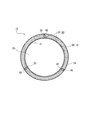
- 2 is a cross-sectional view (cross-sectional view) taken along the line II-II in FIG.
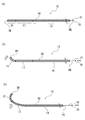
- FIG. 3 is a side view for explaining the operation of the catheter 10 of the present embodiment.
- FIG. 4A is a schematic longitudinal sectional view showing the catheter 10 in a natural state
- FIG. 4B is a schematic longitudinal sectional view showing the catheter 10 in a state where the operation line 40 is slightly pulled.
- c) is a schematic longitudinal sectional view showing the catheter 10 in a state where the operation line 40 is further pulled. In the figure, only one of the three operation lines 40 in the catheter 10 of the present embodiment is illustrated.
- the catheter 10 of this embodiment includes a main lumen 20 and a sub-lumen 30 having a smaller diameter than the main lumen 20.
- a plurality of sublumens 30 are arranged in a distributed manner in the circumferential direction of the main lumen 20, and an operation line 40 fixed to the distal end portion 15 of the catheter 10 includes a plurality of sublumens 30. Each is slidably inserted.
- the catheter 10 of this embodiment will be described in detail.
- a tensile force is applied to the distal end portion 15 of the catheter 10, and the sublumen 30 through which the operation line 40 is inserted.
- the distal end 15 bends to the side.
- the pushing force is not substantially applied from the operation line 40 to the distal end portion 15 of the catheter 10.
- the distal end portion 15 of the catheter 10 refers to a predetermined length region including the distal end DE of the catheter 10.
- the proximal end portion 19 of the catheter 10 refers to a predetermined length region including the proximal end PE of the catheter 10.
- the bending of the catheter 10 means that part or all of the catheter 10 is bent or bent. The present invention does not distinguish between bending and bending. That is, in the present invention, there is a case of bending regardless of the radius of curvature.
- FIG. 2 illustrates a mode in which three sub-lumens 30 are arranged around the main lumen 20 at intervals of 120 degrees.
- the catheter 10 of this embodiment includes a tubular inner layer 21 made of a resin material and having a main lumen 20 formed therein, and a blade layer 50 formed by knitting wires 52 around the inner layer 21. And an outer layer 60 made of the same or different kind of resin material as the inner layer 21 and formed around the inner layer 21 to enclose the blade layer 50.
- the sub-lumen 30 through which the operation lines 40 are inserted is formed inside the outer layer 60 and outside the blade layer 50.
- the main body of the catheter 10 made of a resin material in which the main lumen 20 and the sublumen 30 are formed is referred to as a sheath 16.
- the sublumen 30 is provided along the longitudinal direction of the catheter 10 (left-right direction in FIGS. 1 and 3), and at least the proximal end portion 19 of the catheter 10 is open.
- the proximal end 41 of the operation line 40 protrudes from the proximal end portion 19 to the proximal end side.
- sub-lumen 30 By providing the sub-lumen 30 through which the operation line 40 is inserted apart from the main lumen 20, when the medicine or the like is supplied through the main lumen 20 or when the optical system is inserted, these sub-lumens 30 leak into the sub-lumen 30. There is no. Further, by providing the sub-lumen 30 outside the blade layer 50 as in the present embodiment, the inside of the blade layer 50, that is, the main lumen 20 is protected against the sliding operation line 40. For this reason, even if the operation line 40 is detached from the distal end portion 15 of the catheter 10, the operation line 40 does not tear the peripheral wall of the main lumen 20.
- a hydrophilic coat layer 64 having an outer surface subjected to a lubrication treatment is optionally provided as the outermost layer of the catheter 10.
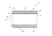
- the distal end portion 15 of the catheter 10 is provided with a ring-shaped marker member 66 made of a material that does not transmit radiation such as X-rays. Specifically, a metal material such as platinum can be used for the marker member 66.
- the marker member 66 of this embodiment is provided around the main lumen 20 and inside the outer layer 60.
- the tip (distal end) of the operation line 40 is fixed to the distal end portion 15 of the catheter 10.
- a mode of fixing the tip of the operation line 40 to the distal end portion 15 is not particularly limited.
- the tip of the operating line 40 may be fastened to the marker member 66, may be welded to the distal end 15 of the sheath 16, or may be adhered to the marker member 66 or the distal end 15 of the sheath 16 with an adhesive. It may be adhered and fixed.
- the catheter 10 may be provided with a plurality of marker members 66 and 67. Further, the tip of the operation line 40 may be fixed to the intermediate position 12 in the distal end portion 15 of the catheter 10 or may be fixed to the distal end DE (see FIG. 9).
- a fluorine-based thermoplastic polymer material can be used for the inner layer 21. More specifically, polytetrafluoroethylene (PTFE), polyvinylidene fluoride (PVDF), perfluoroalkoxy fluororesin (PFA), or the like can be used.
- PTFE polytetrafluoroethylene
- PVDF polyvinylidene fluoride
- PFA perfluoroalkoxy fluororesin
- thermoplastic polymer is widely used for the outer layer 60.
- examples include polyimide (PI), polyamideimide (PAI), polyethylene terephthalate (PET), polyethylene (PE), polyamide (PA), nylon elastomer, polyurethane (PU), ethylene-vinyl acetate resin (EVA), poly Vinyl chloride (PVC) or polypropylene (PP) can be used.
- a fine wire of polymer fiber such as PI, PAI or PET can be used in addition to a fine metal wire such as stainless steel (SUS) or nickel titanium alloy.
- the cross-sectional shape of the wire 52 is not particularly limited, and may be a round line or a flat line.
- the method of inserting the operation line 40 into the sub-lumen 30 can be various.
- the operation line 40 may be inserted from one end side of the sheath 16 of the catheter 10 that is formed through the sub-lumen 30 in advance.
- the operation line 40 may be extruded together with the resin material and inserted into the sub-lumen 30.
- the operation line 40 When the operation line 40 is pushed out together with the resin material and inserted into the sub-lumen 30, the operation line 40 is required to have heat resistance equal to or higher than the melting temperature of the resin material constituting the sheath 16.
- the operation line 40 as specific materials, for example, polyether ether ketone (PEEK), polyphenylene sulfide (PPS), polybutylene terephthalate (PBT), polymer fiber such as PI or PTFE, or SUS, Corrosion-resistant coated steel wires, metal wires such as titanium or titanium alloys can be used.
- the operation line 40 is not required to have heat resistance, such as when the operation line 40 is inserted into the sub-lumen 30 of the sheath 16 formed in advance, in addition to the above materials, PVDF, high-density polyethylene (HDPE) or polyester can also be used.
- PVDF high-density polyethylene
- HDPE high-density polyethylene
- a hydrophilic material such as polyvinyl alcohol (PVA) or polyvinyl pyrrolidone can be used.
- the catheter 10 is provided with an operation portion 70 at the proximal end portion 19 of the catheter 10 that pulls the operation line 40 to bend the distal end portion 15 of the catheter 10.
- the operation unit 70 bends the distal end portion 15 by pulling a plurality of operation lines 40 individually or two or more at the same time.
- the proximal end 41 of the operation line 40 is pulled toward the proximal end (right side in FIG. 3)
- the distal end 15 of the catheter 10 is connected to the catheter 10 via the marker member 66.
- the distal end portion 15 bends to the side of the sub-lumen 30 through which the operation line 40 is inserted by applying a tensile force.
- the catheter 10 is bent toward the intermediate direction between the sub-lumens 30, the two operation lines 40 inserted through the two sub-lumens 30 sandwiching the direction may be pulled together.
- the distal end portion 15 can be bent in an arbitrary direction over 360 degrees by individually controlling the pulling lengths of the three operation lines 40. Thereby, the approach direction of the catheter 10 is changed only by pulling the operation line 40 by the operation unit 70 without performing a torque operation to apply torque to the entire catheter 10 and direct the distal end portion 15 in a predetermined direction. It becomes possible to operate.
- the flexibility of the catheter 10 is increased in a plurality of stages from the proximal end PE side to the distal end DE side. That is, as shown in FIG. 3A, the catheter 10 is partitioned along the longitudinal direction into a distal end portion 15, an intermediate portion 17, and a proximal end portion 19. 17, the flexibility is high, and the distal end portion 15 is more flexible than the intermediate portion 17.
- the flexibility of the catheter 10 refers to the ease of bending when a unit load is applied in the radial direction.
- the order of the diameter of the sheath 16 may be the order of the proximal end portion 19, the intermediate portion 17, and the distal end portion 15.
- the order of the braid density of the blade layer 50 may be the order of the proximal end portion 19, the intermediate portion 17, and the distal end portion 15.
- the followability of the distal end portion 15 by pulling the operation line 40 is improved as shown in FIG.
- the distal end portion 15 can be easily bent toward the operation line 40.
- the intermediate portion 17 can be bent in addition to the distal end portion 15.
- the proximal end 19 to which the bending moment caused by the weight of the catheter 10 is most loaded is made rigid, so that the stiffness of the catheter 10 can be strengthened and form stability can be maintained.
- the flexibility of the catheter 10 continuously increases from the proximal end PE side to the distal end DE side. Specifically, the hardness is continuously increased at the proximal end portion 19 toward the proximal end PE. Accordingly, as shown in FIG. 3C, when the catheter 10 is largely bent, the deformation of the intermediate portion 17 is not hindered by the rigidity of the proximal end portion 19. In other words, according to the present embodiment, the intermediate portion 17 can be sufficiently bent and deformed while maintaining the moment resistance in the vicinity of the proximal end PE of the catheter 10.
- the radius of the main lumen 20 can be about 200 to 300 ⁇ m
- the thickness of the inner layer 21 can be about 10 to 30 ⁇ m
- the thickness of the outer layer 60 can be about 100 to 150 ⁇ m
- the thickness of the blade layer 50 can be 20 to 30 ⁇ m.
- the radius from the axial center of the catheter 10 to the center of the sublumen 30 can be about 300 to 350 ⁇ m
- the inner diameter of the sublumen 30 can be 40 to 100 ⁇ m
- the thickness of the operation line 40 can be 30 to 60 ⁇ m.
- the outermost diameter of the catheter 10 can be about 350 to 450 ⁇ m.
- the outer diameter of the catheter 10 of this embodiment is less than 1 mm in diameter, and can be inserted into blood vessels such as the celiac artery and peripheral blood vessels such as the hepatic artery branch and the internal carotid artery branch.
- the catheter 10 of the present embodiment is freely operated in the direction of travel by pulling the operation line 40, so that the catheter 10 can be advanced in a desired direction even in a branching blood vessel, for example.
- FIG. 3A shows a state where the distal end DE of the catheter 10 inserted into the blood vessel 100 reaches the branching portion 101 of the blood vessel 100.
- the distal end portion 15 of the catheter 10 since the distal end portion 15 of the catheter 10 has high flexibility, the distal end portion 15 is bent at the corner portion 102 of the blood vessel 100 as shown in FIG. In some cases, the travel proceeds in the direction Y corresponding to the extension of the main pipe 104. Therefore, in the catheter 10 of the present embodiment, as shown in FIG. 5C, the proximal end 41 of the operation line 40 is further pulled so that not only the distal end portion 15 but also the intermediate portion 17 is directed in the direction X Can be curved toward.
- the entire traveling direction of the catheter 10 can be changed from the extending direction Y of the main tube 104 to the extending direction X of the blood vessel branch 103. Then, by causing the distal end DE of the catheter 10 to enter the blood vessel branch 103 at a sufficient depth, the intermediate portion 17 and the proximal end portion 19 follow this and enter the blood vessel branch 103.
- the intermediate portion 17 and the proximal end portion 19 have a bending rigidity greater than that of the distal end portion 15. Therefore, even if the intermediate portion 17 or the proximal end portion 19 contacts the corner portion 102, the catheter 10 is no longer bent and enters the main tube 104.
- the catheter 10 of the present embodiment can be advanced in a desired direction even for a branched blood vessel or a peripheral blood vessel.
- the bending angle of the distal end portion 15 exceeds 90 degrees. Therefore, even if the branch angle of the blood vessel 100 is an acute angle that makes a U-turn, the catheter 10 can enter the branch branch.
- FIG. 5 is a schematic longitudinal sectional view of the catheter 10 according to the second embodiment.
- the catheter 10 of this embodiment includes a tubular inner layer 21 made of a resin material and having a main lumen 20 formed therein, a blade layer 50 formed by knitting wires 52 around the inner layer 21, and the same or different kind of inner layer 21. And an outer layer 60 that is formed around the inner layer 21 and encloses the blade layer 50.
- the sub-lumen 30 through which the operation lines 40 are inserted is formed inside the inner layer 21.
- the tip of the operation line 40 inserted through the sub-lumen 30 is welded to the distal end portion 15 of the inner layer 21.
- the operation line 40 since the outer periphery of the sublumen 30 is protected by the blade layer 50, it is assumed that an excessive tensile force is applied to the operation line 40 during operation and this is detached from the distal end portion 15. However, the operation line 40 does not cleave the outer layer 60 and is not exposed to the outside.
- FIG. 6 is a schematic cross-sectional view of the distal end portion 15 of the catheter 10 according to the third embodiment of the present invention.
- two sub-lumens 30 (30a, 30b) through which the operation lines 40 (40a, 40b) are respectively inserted are arranged to face the periphery of the main lumen 20.
- the sub-lumen 30a and the sub-lumen 30b are formed so as to face each other by 180 degrees across the axis of the catheter 10.
- the operation line 40a is inserted through the sub-lumen 30a, and the operation line 40b is inserted through the sub-lumen 30b.
- the operator can bend the distal end 15 of the catheter 10 in a desired direction by rotating the catheter 10 by a maximum of 90 degrees while pulling one of the operation lines 40a or 40b. Can do.
- the entire catheter 10 is drawn in a state where the operation line 40a is pulled and the distal end portion 15 is bent upward in the drawing.
- the torque may be rotated by 90 degrees clockwise.
- the entire catheter 10 may be rotated by 90 degrees in the counterclockwise direction in the figure with the distal end 15 bent downward in the drawing by pulling the operation line 40b.
- the distal end portion 15 can be bent in a desired direction while suppressing the torque rotation of the entire catheter 10 to 90 degrees or less. For this reason, the operator can orient
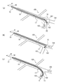
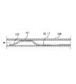
- FIG. 7A is a schematic longitudinal sectional view of the catheter 10 according to the fourth embodiment of the present invention
- FIG. 7B is an enlarged view of the distal end portion 15.
- FIG. 4C is an enlarged view of the distal end portion 15 according to a modification of the present embodiment.
- the catheter 10 of this embodiment is different from the third embodiment in that the distal end portion 15 has a bent shape. And in the catheter 10 of this embodiment, the one operation line 40a is provided in the outer side of the bending direction, and the other operation line 40b is provided in the inner side of the bending direction.
- the distal end 15 of the sheath 16 is shaped, and the first bent portion 151 and the second bent portion 152 are continuous from the intermediate portion 17 on the proximal end side. Is formed.
- the first bent portion 151 and the second bent portion 152 are bent in a common plane. That is, the distal end portion 15 of the present embodiment is bent two-dimensionally in multiple stages.
- the first bent portion 151 and the second bent portion 152 are bent at an angle of approximately 45 degrees with respect to the extending direction of the intermediate portion 17.
- the first bent portion 151 is formed longer than the second bent portion 152.
- the length of the first bent portion 151 can be set to 10 to 15 mm
- the length of the second bent portion 152 can be set to 3 to 10 mm.
- the operation line 40 a and the operation line 40 b are inserted through the sheath 16 until reaching the vicinity of the marker member 66 provided at the most distal end of the distal end portion 15. Is coupled to this.
- the second bent portion 152 is first lifted upward in the drawing, and the bending angle between the first bent portion 151 and the second bent portion 152 is increased. Reduce.
- both the second bent portion 152 and the first bent portion 151 are lifted upward in the drawing, and the first bent portion 151 and the intermediate portion 17 (see the drawing (a)). The bending angle of the is reduced.
- the operation line 40a and the operation line 40b may be coupled to the sheath 16 in the vicinity of the distal end of the first bent portion 151.
- the operation line 40a when the operation line 40a is pulled, the first bent portion 151 is lifted upward in the figure while the bending angle between the second bent portion 152 and the first bent portion 151 remains unchanged.
- the bending angle with respect to the intermediate portion 17 decreases.
- the first bent portion 151 and the second bent portion 152 can be bent in the direction opposite to the above, and the bending angle of the distal end portion 15 can be increased.
- the sheath 16 does not immediately recover to the natural state. In other words, there is a time delay before the retracted sheath 16 returns. Therefore, in the present embodiment, the sheath 16 can be quickly recovered to a natural state by pulling one operation line, removing the pulling force, and then pulling the other operation line.
- FIG. 8 is a schematic longitudinal sectional view showing a state in which the catheter 10 of the present embodiment is inserted into the blood vessel 100.
- the catheter 10 of the present embodiment By pulling the operation line 40a (not shown in the figure) to reduce the bending angle of the second bent portion 152, the catheter 10 of the present embodiment with the bent shape shaped at the tip is obtained.
- a relatively thin blood vessel 100 can be inserted.
- the catheter 10 is torque-rotated so that the second bent portion 152 is bent in the direction of the blood vessel branch 103.
- the second bent portion 152 can be easily entered into the blood vessel branch 103 by relaxing the traction force of the operation line 40a in accordance with the branch direction. At this time, the second bent portion 152 can be caused to enter the vascular branch 103 more easily by pulling the operation line 40b.
- the two-stage bent end portion 15 is illustrated, but the present invention is not limited to this.
- the shape of the shaping of the distal end portion 15 can be arbitrarily selected from a U shape, an L shape, an S shape, an ⁇ shape, a spiral shape, or a combination thereof.
- the curvature is not particularly limited.
- the distal end portion 15 of the sheath 16 is bent from a state in which the manipulation line 40a and the manipulation line 40b are inserted through the straight tubular sheath 16 in advance and the distal end portion is coupled to the sheath 16. It is good to deform.
- the softening point temperature (melting temperature) of the operation lines 40 a and 40 b of this embodiment is higher than the softening point temperature of the sheath 16. Then, when shaping the distal end portion 15 of the sheath 16, the tip of the sheath 16 is heated to a temperature not lower than the softening point temperature of the sheath 16 and lower than the softening point temperature (melting temperature) of the operation wires 40a and 40b.
- the sheath 16 may be bent in a desired direction and then cooled.
- timing for shaping the distal end portion 15 is not particularly limited. That is, shaping may be performed in advance at the time of product shipment of the catheter 10 (pre-shaping), or shaping may be performed on-site immediately before insertion of the catheter 10 into a body vessel such as a blood vessel (re-shaping). Also good.
- Fig.9 (a) is a longitudinal cross-sectional schematic diagram of the catheter 10 concerning 5th embodiment of this invention.
- the operation line 40 (40a, 40b) is fixed to the intermediate position 12 at the distal end portion 15 of the catheter 10.
- the distal end portion 15 of the catheter 10 is provided with the shaping portion 11 on the distal end (distal end DE) side of the operation line 40.
- the shaping portion 11 is formed in a straight line, and is provided as a reshaped scheduled region.
- Marker members 66 and 67 made of a radiopaque material are provided at the distal end (distal end DE) of the distal end portion 15 of the catheter 10 and the intermediate position 12, respectively.
- the intermediate position 12 where the marker member 67 is provided does not need to be the exact center of the distal end portion 15.
- the flexibility of the catheter 10 increases in a plurality of stages from the proximal end side (right side in FIG. 9) to the distal end DE side. Specifically, the distal end portion 15 is lower in the bending elastic modulus of the sheath 16 than the intermediate portion 17 and has high flexibility.
- the distal end portion 15 is further divided into a shaping portion 11 and an active portion 13.
- the active portion 13 is a region on the proximal end side of the operation line 40 at the distal end portion 15 with respect to the fixed end 42.
- the shaping unit 11 is a region at the distal end DE side of the fixed end 42 in the distal end portion 15.
- the marker member 67 is provided in the vicinity of the fixed end 42 of the operation line 40.
- the fixed end 42 of the operation line 40 may be connected to the marker member 67 or may be slightly separated. In other words, the marker member 67 is provided in the boundary region between the shaping part 11 and the active part 13.
- FIG. 9B is a schematic diagram showing a state where the shaping portion 11 is bent by pre-shape or re-shape in the catheter 10 of the present embodiment.
- the shaping part 11 of this embodiment is bent downward in the figure from the marker member 67 toward the distal end DE.
- the bending angle ⁇ of the shaping part 11 is preferably 40 to 50 degrees.
- the catheter 10 can be suitably inserted into a blood vessel that branches or bends at various angles.
- the shaping portion 11 has an axial length of 3 to 10 mm
- the active portion 13 has an axial length of 10 to 20 mm
- the intermediate portion 17 has an axial length of 20 mm or more.
- the distal end portion 15 of the catheter 10 has a bent shape of the shaping portion 11, one operation line 40 b is provided inside the bending direction, and the other operation line 40 a is provided outside the bending direction. .
- FIG. 9C is a schematic diagram showing a state where the operation line 40 a provided outside the bent shape of the shaping portion 11 is pulled.
- the active portion 13 bends toward the operation line 40a.
- the shaping part 11 can maintain a bent shape.
- the catheter 10 of this embodiment can bend the active portion 13 while maintaining the bent shape of the shaping portion 11.
- the intermediate portion 17 of the present embodiment has a sufficiently large bending rigidity as compared with the active portion 13, and when the operation line 40 is pulled, only the active portion 13 is bent.
- the shaping part 11 and the active part 13 have the same bending rigidity and radial dimension of the sheath 16.
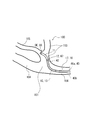
- FIG. 10 is a schematic diagram showing a state in which the catheter 10 of the present embodiment shown in FIG. 9B is inserted into the blood vessel branch 105.
- the figure shows a state in which the shaping portion 11 of the catheter 10 inserted from the right side in the figure into the main tube 104 of the blood vessel 100 has reached the branching portion 101 of the blood vessel 100.
- the catheter 10 of the present embodiment is attached to the distal end DE to which the marker member 66 is attached and the marker member 67 by irradiating the body 100 such as the blood vessel 100 with radiation such as X-rays from outside the body.
- the intermediate position 12 can be visually confirmed. For this reason, it can be detected that the shaping unit 11 has reached the branching portion 101 of the blood vessel 100.
- the first blood vessel branch 103 branches from the main tube 104.
- a second blood vessel branch 105 is branched and formed immediately after the first blood vessel branch 103 is branched. For this reason, in order to allow the catheter 10 to enter the second blood vessel branch 105 from the main tube 104 via the first blood vessel branch 103, it is necessary to bend the catheter 10 in a substantially S shape.
- the fixed end 42 of the operation line 40 is located on the proximal end side with respect to the shaping part 11, and the traction force of the operation line 40 is not applied to the shaping part 11.
- the active part 13 can be bent as it is. For this reason, as shown in FIG. 10, by pulling the operation line 40 a provided outside the bent shape of the shaping portion 11, the catheter 10 is deformed into a substantially S shape, and the distal end provided with the marker member 66 is provided.
- the distal end DE can be suitably pushed into the second blood vessel branch 105.
- the catheter 10 Since the shaping portion 11 has a bent shape, the catheter 10 is torque-rotated without pulling the operation line 40 for a simple branch of the blood vessel 100, so that the bending direction of the shaping portion 11 is changed. Pushing is possible only by adjusting to the branch direction. Thereby, a quick insertion operation into the blood vessel branch 103 is possible.
- the catheter 10 of the present embodiment includes marker members 66 and 67 at both ends of the shaping unit 11, respectively. Further, the marker members 66 and 67 each have an annular shape. For this reason, the position and direction of the marker members 66 and 67 can be grasped by irradiating with radiation. For this reason, not only the position of the distal end DE where the marker member 66 is mounted, but also the position of the intermediate position 12 where the marker member 67 is mounted and the orientation of the shaping portion 11 can be known. As a result, the catheter 10 can be selectively pushed into the blood vessel branches 103 and 105 that branch at various angles.
- FIG. 11A is a schematic diagram of the distal end portion 15 of the catheter 10 according to the sixth embodiment of the present invention.
- FIG. 6B is a schematic view of the distal end portion 15 of the catheter 10 according to the seventh embodiment of the present invention.
- the shaping portion 11 has a two-dimensional or three-dimensional bent shape.
- the shaping portion 11 is formed in a spiral shape and has a loop portion 14, and has a three-dimensional bent shape.
- the shaping portion 11 is formed in a waveform and has a two-dimensional bent shape.
- the operation line 40 is fixed to the marker member 67 and inserted through the active portion 13 and its proximal end side. Thereby, when the operation line 40 is pulled, a load in the bending direction is not applied to the shaping unit 11.
- the catheter 10 of the sixth embodiment is particularly suitable for insertion into a loop-shaped blood vessel formed by cancer cells or the like. That is, when the distal end DE of the catheter 10 in FIG. 11A is pushed into a loop-shaped blood vessel, the loop portion 14 is inserted following the loop shape of the blood vessel.
- the traction force does not act on the shaping portion 11, so that the shaping portion 11 is flexible. It can be freely bent and deformed depending on the nature. For this reason, the loop part 14 of the shaping part 11 follows flexibly corresponding to a loop-shaped blood vessel, and it is possible to insert the catheter 10 without giving an excessive burden to the said blood vessel.
Landscapes
- Health & Medical Sciences (AREA)
- Life Sciences & Earth Sciences (AREA)
- Engineering & Computer Science (AREA)
- Animal Behavior & Ethology (AREA)
- Veterinary Medicine (AREA)
- Biophysics (AREA)
- Public Health (AREA)
- Biomedical Technology (AREA)
- Heart & Thoracic Surgery (AREA)
- General Health & Medical Sciences (AREA)
- Pulmonology (AREA)
- Hematology (AREA)
- Anesthesiology (AREA)
- Surgery (AREA)
- Mechanical Engineering (AREA)
- Physics & Mathematics (AREA)
- Nuclear Medicine, Radiotherapy & Molecular Imaging (AREA)
- Optics & Photonics (AREA)
- Pathology (AREA)
- Radiology & Medical Imaging (AREA)
- Medical Informatics (AREA)
- Molecular Biology (AREA)
- Media Introduction/Drainage Providing Device (AREA)
Abstract
Description
押し/引きワイヤは、ガイドワイヤを挿通する主管腔よりも小径のワイヤ管腔に貫通されており、これを引っ張ることでワイヤ管腔側にカテーテルの遠位端が屈曲し、押し込むことで逆側に屈曲するとされている。
第一には、押し/引きワイヤをカテーテルに押し込んだ場合に、カテーテルの遠位端はワイヤ管腔と逆側には必ずしも屈曲しないことである。すなわち、押し/引きワイヤを引っ張った場合にはカテーテルの遠位端がワイヤ管腔側に屈曲することが予想されるものの、押し/引きワイヤを押し込んだ場合には、遠位端はもっぱら真っ直ぐ伸張されるに留まり、ワイヤ管腔の逆側には屈曲しない。かりに押し/引きワイヤの押し込みによってワイヤ管腔と逆側に遠位端が屈曲するとしても、かかる屈曲は僅かであって、ワイヤの引っ張りと押し込みとでそれぞれ得られる屈曲量は非対称である。したがって、上記発明ではカテーテルの進行方向の調整能力を十分に得ることが困難である。
第二には、上記発明の押し/引きワイヤは、これを押し込んだ場合にカテーテルの遠位端を屈曲させることができる程度に高い剛性を有している。したがって、操作者の押し込み操作によって過度の押し込み力が遠位端に生じた場合には、押し/引きワイヤがカテーテルの遠位端を突き破って体腔内に突出する恐れがある。
また、前記操作線がそれぞれ挿通された2つの前記サブルーメンが前記メインルーメンの周囲に対向して配置されていてもよい。
また、前記操作線を牽引して前記カテーテルの遠位端部を屈曲させる操作部が、前記カテーテルの近位端部に設けられていてもよい。
また、前記操作線は前記カテーテルの前記遠位端部における中間位置に固定されており、前記遠位端部には、前記操作線よりも先端側にシェイピング部が設けられていてもよい。
また、前記遠位端部における先端と前記中間位置とに、放射線不透過材料からなるマーカー部材がそれぞれ設けられていてもよい。
また、前記シェイピング部が二次元的または三次元的な屈曲形状をなしていてもよい。
また、前記カテーテルの遠位端部が屈曲形状をなし、一の前記操作線が屈曲方向の内側に設けられ、他の前記操作線が屈曲方向の外側に設けられていてもよい。
また、前記カテーテルの近位端側から遠位端側にかけて、前記カテーテルの可撓性が複数段階に増大していてもよい。
図2は、図1のII-II断面図(横断面図)である。
図3は、本実施形態のカテーテル10の動作を説明する側面図である。同図(a)は自然状態のカテーテル10を示す縦断面模式図であり、同図(b)は操作線40を僅かに牽引した状態のカテーテル10を示す縦断面模式図であり、同図(c)は操作線40をさらに牽引した状態のカテーテル10を示す縦断面模式図である。同図では、本実施形態のカテーテル10における3本の操作線40のうち、1本のみを図示している。
本実施形態のカテーテル10は、メインルーメン20と、メインルーメン20よりも小径のサブルーメン30と、を備えている。
そして、カテーテル10は、複数のサブルーメン30がメインルーメン20の周方向に分散して配置されているとともに、カテーテル10の遠位端部15に固定された操作線40が、複数のサブルーメン30にそれぞれ摺動可能に挿通されている。
本実施形態のカテーテル10において、操作線40の近位端41を牽引した場合には、カテーテル10の遠位端部15に引張力が与えられて、当該操作線40が挿通されたサブルーメン30の側に遠位端部15が屈曲する。
一方、操作線40の近位端41をカテーテル10に対して押し込んだ場合には、当該操作線40からカテーテル10の遠位端部15に対して押込力が実質的に与えられることはない。
また、カテーテル10が屈曲するとは、カテーテル10の一部または全部が、湾曲または折れ曲がって曲がることをいう。本発明では屈曲と湾曲とを区別しない。すなわち、曲率半径の大小によらず本発明では屈曲という場合がある。
そして、カテーテル10は、操作線40がそれぞれ挿通されたサブルーメン30が、外層60の内部であってブレード層50の外側に形成されている。
サブルーメン30はカテーテル10の長手方向(図1、3における左右方向)に沿って設けられ、少なくともカテーテル10の近位端部19が開口している。操作線40の近位端41は近位端部19から基端側に突出している。
そして、本実施形態のようにサブルーメン30をブレード層50の外部に設けることにより、摺動する操作線40に対して、ブレード層50の内部、すなわちメインルーメン20が保護される。このため、かりに操作線40がカテーテル10の遠位端部15から外れたとしても、操作線40がメインルーメン20の周壁を開裂してしまうことがない。
カテーテル10の遠位端部15には、X線等の放射線が不透過な材料からなるリング状のマーカー部材66が設けられている。具体的には、マーカー部材66には白金などの金属材料を用いることができる。本実施形態のマーカー部材66は、メインルーメン20の周囲であって外層60の内部に設けられている。
内層21にフッ素系樹脂を用いることにより、カテーテル10のメインルーメン20を通じて造影剤や薬液などを患部に供給する際のデリバリー性が良好となる。
ワイヤ52の断面形状は特に限定されず、丸線でも平線でもよい。
一方、予め成形されたシース16のサブルーメン30に対して操作線40を挿通する場合など、操作線40に耐熱性が求められない場合は、上記各材料に加えて、PVDF、高密度ポリエチレン(HDPE)またはポリエステルなどを使用することもできる。
本実施形態のカテーテル10においては、操作線40の近位端41を基端側(図3における右方)に牽引した場合には、マーカー部材66を介してカテーテル10の遠位端部15に引張力が与えられて、当該操作線40が挿通されたサブルーメン30の側に遠位端部15が屈曲する。
カテーテル10を、サブルーメン30同士の中間方向に向かって屈曲させる場合は、当該方向を挟む2つのサブルーメン30に挿通された2本の操作線40を共に牽引すればよい。
すなわち、図3(a)に示すように、カテーテル10は長手方向に沿って遠位端部15、中間部17および近位端部19に区画されており、近位端部19よりも中間部17において可撓性が高く、さらに中間部17よりも遠位端部15において可撓性が高くなっている。
ここで、カテーテル10の可撓性とは、径方向に単位荷重を付与した場合の曲がりやすさをいう。
また、図3(c)に示すように、操作線40の牽引量を増加させた場合には、遠位端部15に加えて中間部17を屈曲させることができる。
一方、カテーテル10の自重に起因する曲げモーメントがもっとも負荷される近位端部19をリジッドとすることにより、カテーテル10のコシを強くし、形態安定性を保つことができる。
具体的には、近位端部19において、近位端PEに向かって硬度を連続的に増大させている。
これにより、図3(c)に示すようにカテーテル10を大きく屈曲させる際に、近位端部19の剛性に拘束されて中間部17の変形が阻害されることがない。言い換えると、本実施形態によれば、カテーテル10の近位端PE近傍における耐モーメント性を維持しつつ、中間部17を十分に屈曲変形させることができる。
メインルーメン20の半径は200~300μm程度、内層21の厚さは10~30μm程度、外層60の厚さは100~150μm程度、ブレード層50の厚さは20~30μmとすることができる。そして、カテーテル10の軸心からサブルーメン30の中心までの半径は300~350μm程度、サブルーメン30の内径は40~100μmとし、操作線40の太さを30~60μmとすることができる。そして、カテーテル10の最外径を350~450μm程度とすることができる。
すなわち、本実施形態のカテーテル10の外径は直径1mm未満であり、腹腔動脈などの血管、および肝動脈枝や内頚動脈枝などの末梢血管に挿通可能である。また、本実施形態のカテーテル10に関しては、操作線40の牽引により進行方向が自在に操作されるため、たとえば分岐する血管内においても所望の方向にカテーテル10を進入させることが可能である。
同図(a)は、血管100内に挿通されたカテーテル10の遠位端DEが、血管100の分岐部101に至った状態を示している。
ここで、分岐部101より血管枝103に向かって、図中の矢印の示す方向Xにカテーテル10を進行させることを試みる。そこで、同図(a)に示すように、カテーテル10における3本の操作線40のうちの1本または2本を牽引して、遠位端部15を方向Xに屈曲させたとする。
そこで、本実施形態のカテーテル10では、同図(c)に示すように、操作線40の近位端41をさらに牽引することにより、遠位端部15のみならず中間部17をも方向Xに向かって湾曲させることができる。
そして、カテーテル10の遠位端DEを血管枝103に十分な深さで進入させることにより、中間部17および近位端部19はこれに追随して血管枝103に進入していく。そして、中間部17や近位端部19は、遠位端部15よりも大きな曲げ剛性を有している。したがって、かりに中間部17や近位端部19がコーナー部102に接触したとしても、もはやカテーテル10が折れ曲がって主管104に進入することはない。
以上より、分岐のある血管や末梢血管に対しても、本実施形態のカテーテル10を所望の方向に進入させることができる。
図5は、第二実施形態にかかるカテーテル10の縦断面模式図である。
そして、カテーテル10は、操作線40がそれぞれ挿通されたサブルーメン30が、内層21の内部に形成されている。
本実施形態のカテーテル10においては、操作線40(40a、40b)がそれぞれ挿通された2つのサブルーメン30(30a、30b)が、メインルーメン20の周囲に対向して配置されている。
たとえば、図6においてカテーテル10の遠位端部15を図中右方に屈曲させる場合、操作線40aを牽引して遠位端部15を図中上方に屈曲させた状態で、カテーテル10の全体を同図にて時計回りに90度だけトルク回転させればよい。または、操作線40bを牽引して遠位端部15を図中下方に屈曲させた状態で、カテーテル10の全体を同図にて反時計回りに90度だけトルク回転させてもよい。
本実施形態の操作線40a、40bの軟化点温度(溶融温度)は、シース16の軟化点温度よりも高い。そして、シース16の遠位端部15をシェイピングするにあたっては、シース16の軟化点温度以上、かつ操作線40a、40bの軟化点温度(溶融温度)未満の温度にシース16の先端を加熱して、所望の方向にシース16を屈曲させ、その後に冷却するとよい。
本実施形態のカテーテル10は、操作線40(40a、40b)がカテーテル10の遠位端部15における中間位置12に固定されている。そして、カテーテル10の遠位端部15には、操作線40よりも先端(遠位端DE)側にシェイピング部11が設けられている。
マーカー部材67は、操作線40の固定端42の近傍に設けられている。操作線40の固定端42はマーカー部材67に連結されていてもよく、または僅かに離間していてもよい。言い換えると、マーカー部材67はシェイピング部11と能動部13との境界領域に設けられている。
本実施形態のカテーテル10では、シェイピング部11を3~10mm、能動部13を10~20mm、中間部17を20mm以上の軸長とするとよい。
このため、主管104から第一の血管枝103を経由して第二の血管枝105にカテーテル10を進入させるためには、カテーテル10を略S字状に屈曲させる必要がある。
これにより、様々な角度で分岐する血管枝103、105に対して選択的にカテーテル10を押し込んでいくことができる。
ここで、操作線40を牽引して能動部13の先端(マーカー部材67)を所定の血管枝に志向させたとしてもシェイピング部11にはこの牽引力が作用しないため、シェイピング部11はその可撓性により自由に曲げ変形することができる。このため、ループ状の血管に対応してシェイピング部11のループ部14が柔軟に追随し、当該血管に過大な負担を与えることなくカテーテル10を挿入することが可能である。
Claims (13)
- メインルーメンと、前記メインルーメンよりも小径のサブルーメンと、を備えるカテーテルであって、
複数の前記サブルーメンが前記メインルーメンの周方向に分散して配置されているとともに、
前記カテーテルの遠位端部に固定された操作線が、複数の前記サブルーメンにそれぞれ摺動可能に挿通されていることを特徴とするカテーテル。 - 前記操作線の近位端を牽引した場合には、前記カテーテルの遠位端部に引張力が与えられて、当該操作線が挿通された前記サブルーメンの側に前記遠位端部が屈曲し、
前記操作線の近位端を前記カテーテルに対して押し込んだ場合には、当該操作線から前記カテーテルの遠位端部に対して押込力が実質的に与えられない
ことを特徴とする請求項1に記載のカテーテル。 - 前記操作線がそれぞれ挿通された3つ以上の前記サブルーメンが前記メインルーメンの周方向に分散して配置されていることを特徴とする請求項1または2に記載のカテーテル。
- 前記操作線がそれぞれ挿通された2つの前記サブルーメンが前記メインルーメンの周囲に対向して配置されていることを特徴とする請求項1または2に記載のカテーテル。
- 前記操作線を牽引して前記カテーテルの遠位端部を屈曲させる操作部が、前記カテーテルの近位端部に設けられていることを特徴とする請求項1から4のいずれかに記載のカテーテル。
- 前記操作線は前記カテーテルの前記遠位端部における中間位置に固定されており、
前記遠位端部には、前記操作線よりも先端側にシェイピング部が設けられていることを特徴とする請求項1から5のいずれかに記載のカテーテル。 - 前記遠位端部における先端と前記中間位置とに、放射線不透過材料からなるマーカー部材がそれぞれ設けられていることを特徴とする請求項6に記載のカテーテル。
- 前記シェイピング部が二次元的または三次元的な屈曲形状をなしている請求項6または7に記載のカテーテル。
- 前記カテーテルの前記遠位端部が屈曲形状をなし、
一の前記操作線が屈曲方向の内側に設けられ、他の前記操作線が屈曲方向の外側に設けられていることを特徴とする請求項1から8のいずれかに記載のカテーテル。 - 前記カテーテルの近位端側から遠位端側にかけて、前記カテーテルの可撓性が複数段階に増大していることを特徴とする請求項1から9のいずれかに記載のカテーテル。
- 前記カテーテルの少なくとも一部長さ領域において、前記カテーテルの可撓性が、前記カテーテルの近位端側から遠位端側にかけて連続的に増大していることを特徴とする請求項1から10のいずれかに記載のカテーテル。
- 樹脂材料からなり前記メインルーメンが内部に形成された管状の内層と、前記内層の周囲にワイヤを編成してなるブレード層と、前記内層と同種または異種の樹脂材料からなり前記内層の周囲に形成されて前記ブレード層を内包する外層と、を有する請求項1から11のいずれかに記載のカテーテルであって、
前記操作線がそれぞれ挿通された前記サブルーメンが、前記内層の内部に形成されていることを特徴とするカテーテル。 - 樹脂材料からなり前記メインルーメンが内部に形成された管状の内層と、前記内層の周囲にワイヤを編成してなるブレード層と、前記内層と同種または異種の樹脂材料からなり前記内層の周囲に形成されて前記ブレード層を内包する外層と、を有する請求項1から11のいずれかに記載のカテーテルであって、
前記操作線がそれぞれ挿通された前記サブルーメンが、前記外層の内部であって前記ブレード層の外側に形成されていることを特徴とするカテーテル。
Priority Applications (4)
| Application Number | Priority Date | Filing Date | Title |
|---|---|---|---|
| CN2009801527300A CN102264428A (zh) | 2008-12-26 | 2009-12-24 | 导管 |
| JP2010543869A JP5724382B2 (ja) | 2008-12-26 | 2009-12-24 | カテーテル |
| EP09834453A EP2371415A4 (en) | 2008-12-26 | 2009-12-24 | CATHETER |
| US13/142,390 US20110270229A1 (en) | 2008-12-26 | 2009-12-24 | Catheter |
Applications Claiming Priority (4)
| Application Number | Priority Date | Filing Date | Title |
|---|---|---|---|
| JP2008332204 | 2008-12-26 | ||
| JP2008-332204 | 2008-12-26 | ||
| JP2009108473 | 2009-04-27 | ||
| JP2009-108473 | 2009-04-27 |
Publications (1)
| Publication Number | Publication Date |
|---|---|
| WO2010073646A1 true WO2010073646A1 (ja) | 2010-07-01 |
Family
ID=42287293
Family Applications (1)
| Application Number | Title | Priority Date | Filing Date |
|---|---|---|---|
| PCT/JP2009/007158 Ceased WO2010073646A1 (ja) | 2008-12-26 | 2009-12-24 | カテーテル |
Country Status (6)
| Country | Link |
|---|---|
| US (1) | US20110270229A1 (ja) |
| EP (1) | EP2371415A4 (ja) |
| JP (1) | JP5724382B2 (ja) |
| KR (1) | KR20110117116A (ja) |
| CN (1) | CN102264428A (ja) |
| WO (1) | WO2010073646A1 (ja) |
Cited By (6)
| Publication number | Priority date | Publication date | Assignee | Title |
|---|---|---|---|---|
| JP2012061070A (ja) * | 2010-09-15 | 2012-03-29 | Sumitomo Bakelite Co Ltd | カテーテル |
| WO2014098011A1 (ja) * | 2012-12-18 | 2014-06-26 | 住友ベークライト株式会社 | 医療機器 |
| JP2017535376A (ja) * | 2014-12-01 | 2017-11-30 | コーニンクレッカ フィリップス エヌ ヴェKoninklijke Philips N.V. | 器用な偏向制御のためのプルワイヤを備える事前湾曲させられた操縦可能なカテーテル |
| JPWO2021166057A1 (ja) * | 2020-02-18 | 2021-08-26 | ||
| JP2024504704A (ja) * | 2021-01-22 | 2024-02-01 | マイクロライナー テクノロジーズ,インコーポレイテッド | ガイドワイヤに沿った非外傷性カテーテル挿入のためのシステムおよび装置 |
| WO2025204551A1 (ja) * | 2024-03-25 | 2025-10-02 | ソニーグループ株式会社 | 情報処理装置、情報処理方法、およびプログラム |
Families Citing this family (22)
| Publication number | Priority date | Publication date | Assignee | Title |
|---|---|---|---|---|
| DE102013008159A1 (de) | 2012-05-14 | 2013-11-14 | Thoratec Corporation | Mantelsystem für Katheterpumpe |
| GB2504176A (en) | 2012-05-14 | 2014-01-22 | Thoratec Corp | Collapsible impeller for catheter pump |
| JP5885302B2 (ja) * | 2012-10-29 | 2016-03-15 | 日本ライフライン株式会社 | 医療機器 |
| US11077294B2 (en) * | 2013-03-13 | 2021-08-03 | Tc1 Llc | Sheath assembly for catheter pump |
| US10363349B2 (en) | 2014-04-15 | 2019-07-30 | Tc1 Llp | Heart pump providing adjustable outflow |
| CA2946324C (en) * | 2014-05-02 | 2023-03-21 | Intellimedical Technologies Pty Ltd | Elongate steerable devices for insertion into a subject's body |
| JP6570123B2 (ja) * | 2016-02-29 | 2019-09-04 | 日本ライフライン株式会社 | 心腔内除細動カテーテル |
| US10898684B2 (en) * | 2016-09-23 | 2021-01-26 | Sanovas Intellectual Property, Llc | Non-buckling steerable catheter |
| WO2018169032A1 (ja) * | 2017-03-16 | 2018-09-20 | テルモ株式会社 | カテーテル組立体 |
| CN108354579A (zh) * | 2018-01-14 | 2018-08-03 | 宁波高新区世代能源科技有限公司 | 智能肠胃镜 |
| CN109330545A (zh) * | 2018-10-11 | 2019-02-15 | 苏州中科先进技术研究院有限公司 | 一种双侧驱动的四向蛇骨及内窥镜 |
| CN109349984A (zh) * | 2018-11-09 | 2019-02-19 | 苏州新光维医疗科技有限公司 | 一种具有编织丝结构的柔性渐变式内窥镜导管 |
| CN109771706A (zh) * | 2019-01-17 | 2019-05-21 | 广东省人民医院(广东省医学科学院) | 吸痰管 |
| WO2020220113A1 (en) | 2019-04-29 | 2020-11-05 | North Star Specialists Inc. | Marker band pull wire assembly and method of use thereof |
| US20220386851A1 (en) * | 2019-11-13 | 2022-12-08 | Scivita Medical Technology Co., Ltd. | Endoscope structure |
| JP7555185B2 (ja) * | 2019-12-02 | 2024-09-24 | 朝日インテック株式会社 | カテーテル |
| CN111012994A (zh) * | 2020-01-07 | 2020-04-17 | 邢海洋 | 一种可视吸痰管 |
| CN114191685A (zh) * | 2021-10-19 | 2022-03-18 | 深圳北芯医疗科技有限公司 | 导管鞘 |
| KR102852103B1 (ko) * | 2022-11-11 | 2025-08-29 | 계명대학교 산학협력단 | 스테인리스 링을 구비하는 말단 각도 조절이 가능한 카테터 장치 및 이를 이용하는 방법 |
| US11950765B1 (en) * | 2023-04-29 | 2024-04-09 | Syncrobotix, Inc. | Highly maneuverable surgical catheter and bronchoscope |
| US12127805B1 (en) * | 2023-04-29 | 2024-10-29 | Syncrobotix, Inc. | Highly maneuverable surgical catheter and drive system |
| US12127804B1 (en) * | 2023-04-29 | 2024-10-29 | Syncrobotix, Inc. | Simplified highly maneuverable surgical catheter and bronchoscope |
Citations (11)
| Publication number | Priority date | Publication date | Assignee | Title |
|---|---|---|---|---|
| JPH05345031A (ja) * | 1992-06-16 | 1993-12-27 | Tougou Medeikitsuto Kk | カテーテル |
| JPH08252319A (ja) * | 1995-03-15 | 1996-10-01 | Olympus Optical Co Ltd | 可撓管の湾曲機構 |
| JPH09506541A (ja) * | 1995-04-28 | 1997-06-30 | ターゲット セラピューティクス, インコーポレイテッド | 高性能ブレードカテーテル |
| JP2006061350A (ja) * | 2004-08-26 | 2006-03-09 | Japan Lifeline Co Ltd | 先端偏向操作可能カテーテル |
| JP2007061311A (ja) * | 2005-08-30 | 2007-03-15 | Piolax Medical Device:Kk | カテーテル |
| WO2007035554A1 (en) * | 2005-09-16 | 2007-03-29 | Biosense Webster, Inc. | Catheter with flexible pre-shaped tip section |
| JP2007507305A (ja) | 2003-10-01 | 2007-03-29 | ミクラス エンドバスキュラー コーポレイション | 方向操作可能なバルーン・カテーテル |
| JP2007319594A (ja) * | 2006-06-05 | 2007-12-13 | Kaneka Corp | 医療用カテーテルチューブ |
| JP2008245765A (ja) * | 2007-03-29 | 2008-10-16 | Japan Lifeline Co Ltd | 先端偏向操作可能カテーテル |
| JP2008264104A (ja) * | 2007-04-18 | 2008-11-06 | Hirakawa Hewtech Corp | カテーテル用チューブの製造方法 |
| JP2009108473A (ja) | 2007-10-26 | 2009-05-21 | Ishizukagumi:Kk | 高所構造物に対する吊り足場架設方法 |
Family Cites Families (14)
| Publication number | Priority date | Publication date | Assignee | Title |
|---|---|---|---|---|
| EP0420993B1 (en) * | 1989-04-13 | 1995-02-15 | Mitsubishi Cable Industries, Ltd. | Catheter |
| US6096036A (en) * | 1998-05-05 | 2000-08-01 | Cardiac Pacemakers, Inc. | Steerable catheter with preformed distal shape and method for use |
| US5916147A (en) * | 1997-09-22 | 1999-06-29 | Boury; Harb N. | Selectively manipulable catheter |
| US20040199052A1 (en) * | 2003-04-01 | 2004-10-07 | Scimed Life Systems, Inc. | Endoscopic imaging system |
| JP2004329254A (ja) * | 2003-04-30 | 2004-11-25 | Japan Lifeline Co Ltd | 先端偏向操作可能カテーテル |
| US20050064223A1 (en) * | 2003-09-22 | 2005-03-24 | Bavaro Vincent Peter | Polymeric marker with high radiopacity |
| CA2558796C (en) * | 2004-03-23 | 2016-10-04 | Boston Scientific Limited | In-vivo visualization system |
| US20060252993A1 (en) * | 2005-03-23 | 2006-11-09 | Freed David I | Medical devices and systems |
| WO2006122061A1 (en) * | 2005-05-06 | 2006-11-16 | Acumen Medical, Inc. | Complexly shaped steerable catheters and methods for making and using them |
| US8298210B2 (en) * | 2005-10-26 | 2012-10-30 | Medtronic Vascular, Inc. | Catheter having oval aspiration lumen and method of making |
| US7867169B2 (en) * | 2005-12-02 | 2011-01-11 | Abbott Cardiovascular Systems Inc. | Echogenic needle catheter configured to produce an improved ultrasound image |
| US9155452B2 (en) * | 2007-04-27 | 2015-10-13 | Intuitive Surgical Operations, Inc. | Complex shape steerable tissue visualization and manipulation catheter |
| US20080300462A1 (en) * | 2007-05-31 | 2008-12-04 | Boston Scientific Scimed, Inc. | Active controlled bending in medical devices |
| US8096985B2 (en) * | 2008-05-07 | 2012-01-17 | Guided Delivery Systems Inc. | Deflectable guide |
-
2009
- 2009-12-24 EP EP09834453A patent/EP2371415A4/en not_active Withdrawn
- 2009-12-24 KR KR1020117017523A patent/KR20110117116A/ko not_active Ceased
- 2009-12-24 CN CN2009801527300A patent/CN102264428A/zh active Pending
- 2009-12-24 US US13/142,390 patent/US20110270229A1/en not_active Abandoned
- 2009-12-24 JP JP2010543869A patent/JP5724382B2/ja active Active
- 2009-12-24 WO PCT/JP2009/007158 patent/WO2010073646A1/ja not_active Ceased
Patent Citations (11)
| Publication number | Priority date | Publication date | Assignee | Title |
|---|---|---|---|---|
| JPH05345031A (ja) * | 1992-06-16 | 1993-12-27 | Tougou Medeikitsuto Kk | カテーテル |
| JPH08252319A (ja) * | 1995-03-15 | 1996-10-01 | Olympus Optical Co Ltd | 可撓管の湾曲機構 |
| JPH09506541A (ja) * | 1995-04-28 | 1997-06-30 | ターゲット セラピューティクス, インコーポレイテッド | 高性能ブレードカテーテル |
| JP2007507305A (ja) | 2003-10-01 | 2007-03-29 | ミクラス エンドバスキュラー コーポレイション | 方向操作可能なバルーン・カテーテル |
| JP2006061350A (ja) * | 2004-08-26 | 2006-03-09 | Japan Lifeline Co Ltd | 先端偏向操作可能カテーテル |
| JP2007061311A (ja) * | 2005-08-30 | 2007-03-15 | Piolax Medical Device:Kk | カテーテル |
| WO2007035554A1 (en) * | 2005-09-16 | 2007-03-29 | Biosense Webster, Inc. | Catheter with flexible pre-shaped tip section |
| JP2007319594A (ja) * | 2006-06-05 | 2007-12-13 | Kaneka Corp | 医療用カテーテルチューブ |
| JP2008245765A (ja) * | 2007-03-29 | 2008-10-16 | Japan Lifeline Co Ltd | 先端偏向操作可能カテーテル |
| JP2008264104A (ja) * | 2007-04-18 | 2008-11-06 | Hirakawa Hewtech Corp | カテーテル用チューブの製造方法 |
| JP2009108473A (ja) | 2007-10-26 | 2009-05-21 | Ishizukagumi:Kk | 高所構造物に対する吊り足場架設方法 |
Non-Patent Citations (1)
| Title |
|---|
| See also references of EP2371415A4 * |
Cited By (8)
| Publication number | Priority date | Publication date | Assignee | Title |
|---|---|---|---|---|
| JP2012061070A (ja) * | 2010-09-15 | 2012-03-29 | Sumitomo Bakelite Co Ltd | カテーテル |
| WO2014098011A1 (ja) * | 2012-12-18 | 2014-06-26 | 住友ベークライト株式会社 | 医療機器 |
| JP2017535376A (ja) * | 2014-12-01 | 2017-11-30 | コーニンクレッカ フィリップス エヌ ヴェKoninklijke Philips N.V. | 器用な偏向制御のためのプルワイヤを備える事前湾曲させられた操縦可能なカテーテル |
| JPWO2021166057A1 (ja) * | 2020-02-18 | 2021-08-26 | ||
| WO2021166057A1 (ja) * | 2020-02-18 | 2021-08-26 | 日本ライフライン株式会社 | 電極カテーテル |
| JP2024504704A (ja) * | 2021-01-22 | 2024-02-01 | マイクロライナー テクノロジーズ,インコーポレイテッド | ガイドワイヤに沿った非外傷性カテーテル挿入のためのシステムおよび装置 |
| JP7820837B2 (ja) | 2021-01-22 | 2026-02-26 | マイクロライナー テクノロジーズ,インコーポレイテッド | ガイドワイヤに沿った非外傷性カテーテル挿入のためのシステムおよび装置 |
| WO2025204551A1 (ja) * | 2024-03-25 | 2025-10-02 | ソニーグループ株式会社 | 情報処理装置、情報処理方法、およびプログラム |
Also Published As
| Publication number | Publication date |
|---|---|
| CN102264428A (zh) | 2011-11-30 |
| US20110270229A1 (en) | 2011-11-03 |
| EP2371415A1 (en) | 2011-10-05 |
| JPWO2010073646A1 (ja) | 2012-06-07 |
| KR20110117116A (ko) | 2011-10-26 |
| JP5724382B2 (ja) | 2015-05-27 |
| EP2371415A4 (en) | 2012-06-27 |
Similar Documents
| Publication | Publication Date | Title |
|---|---|---|
| JP5724382B2 (ja) | カテーテル | |
| JP5452026B2 (ja) | カテーテル | |
| JP5604974B2 (ja) | カテーテル | |
| US11951262B2 (en) | Catheter devices and methods for making them | |
| KR102724146B1 (ko) | 카테터 및 카테터의 제조 방법 | |
| US9427551B2 (en) | Steerable catheters and methods for making them | |
| JP6149855B2 (ja) | 医療機器 | |
| JP5636656B2 (ja) | カテーテル | |
| WO2013146673A1 (ja) | 医療機器および医療機器の製造方法 | |
| JP2010227137A (ja) | カテーテル | |
| JP2012213478A (ja) | 医療用機器 | |
| JP5927974B2 (ja) | 医療機器 | |
| EP3331595B1 (en) | Catheter devices and methods for making them | |
| JP2014188216A (ja) | 医療用機器および医療用機器の製造方法 | |
| JP2014111139A (ja) | カテーテル | |
| JP5446488B2 (ja) | カテーテルの製造方法 | |
| JP6792587B2 (ja) | 医療機器および医療機器の製造方法 | |
| US20130289498A1 (en) | Catheter and Method for Making a Catheter | |
| JP2016214942A (ja) | 医療機器および医療機器の製造方法 | |
| JP6885037B2 (ja) | 医療機器 | |
| JP2013208150A (ja) | カテーテル | |
| JP5212092B2 (ja) | カテーテルの製造方法 | |
| JP2017158958A (ja) | ガイドワイヤ | |
| JP2012213432A (ja) | 医療用器具及び医療用器具の製造方法 |
Legal Events
| Date | Code | Title | Description |
|---|---|---|---|
| WWE | Wipo information: entry into national phase |
Ref document number: 200980152730.0 Country of ref document: CN |
|
| 121 | Ep: the epo has been informed by wipo that ep was designated in this application |
Ref document number: 09834453 Country of ref document: EP Kind code of ref document: A1 |
|
| ENP | Entry into the national phase |
Ref document number: 2010543869 Country of ref document: JP Kind code of ref document: A |
|
| REEP | Request for entry into the european phase |
Ref document number: 2009834453 Country of ref document: EP |
|
| WWE | Wipo information: entry into national phase |
Ref document number: 2009834453 Country of ref document: EP |
|
| NENP | Non-entry into the national phase |
Ref country code: DE |
|
| WWE | Wipo information: entry into national phase |
Ref document number: 13142390 Country of ref document: US |
|
| ENP | Entry into the national phase |
Ref document number: 20117017523 Country of ref document: KR Kind code of ref document: A |