WO2010073672A1 - 遮蔽板およびその遮蔽板を備える車両構造 - Google Patents
遮蔽板およびその遮蔽板を備える車両構造 Download PDFInfo
- Publication number
- WO2010073672A1 WO2010073672A1 PCT/JP2009/007199 JP2009007199W WO2010073672A1 WO 2010073672 A1 WO2010073672 A1 WO 2010073672A1 JP 2009007199 W JP2009007199 W JP 2009007199W WO 2010073672 A1 WO2010073672 A1 WO 2010073672A1
- Authority
- WO
- WIPO (PCT)
- Prior art keywords
- flat plate
- shielding plate
- bent
- shielding
- fragile
- Prior art date
- Legal status (The legal status is an assumption and is not a legal conclusion. Google has not performed a legal analysis and makes no representation as to the accuracy of the status listed.)
- Ceased
Links
Images









Classifications
-
- B—PERFORMING OPERATIONS; TRANSPORTING
- B62—LAND VEHICLES FOR TRAVELLING OTHERWISE THAN ON RAILS
- B62D—MOTOR VEHICLES; TRAILERS
- B62D29/00—Superstructures, understructures, or sub-units thereof, characterised by the material thereof
- B62D29/001—Superstructures, understructures, or sub-units thereof, characterised by the material thereof characterised by combining metal and synthetic material
- B62D29/002—Superstructures, understructures, or sub-units thereof, characterised by the material thereof characterised by combining metal and synthetic material a foamable synthetic material or metal being added in situ
-
- B—PERFORMING OPERATIONS; TRANSPORTING
- B62—LAND VEHICLES FOR TRAVELLING OTHERWISE THAN ON RAILS
- B62D—MOTOR VEHICLES; TRAILERS
- B62D25/00—Superstructure or monocoque structure sub-units; Parts or details thereof not otherwise provided for
- B62D25/08—Front or rear portions
- B62D25/081—Cowls
-
- Y—GENERAL TAGGING OF NEW TECHNOLOGICAL DEVELOPMENTS; GENERAL TAGGING OF CROSS-SECTIONAL TECHNOLOGIES SPANNING OVER SEVERAL SECTIONS OF THE IPC; TECHNICAL SUBJECTS COVERED BY FORMER USPC CROSS-REFERENCE ART COLLECTIONS [XRACs] AND DIGESTS
- Y10—TECHNICAL SUBJECTS COVERED BY FORMER USPC
- Y10T—TECHNICAL SUBJECTS COVERED BY FORMER US CLASSIFICATION
- Y10T428/00—Stock material or miscellaneous articles
- Y10T428/15—Sheet, web, or layer weakened to permit separation through thickness
-
- Y—GENERAL TAGGING OF NEW TECHNOLOGICAL DEVELOPMENTS; GENERAL TAGGING OF CROSS-SECTIONAL TECHNOLOGIES SPANNING OVER SEVERAL SECTIONS OF THE IPC; TECHNICAL SUBJECTS COVERED BY FORMER USPC CROSS-REFERENCE ART COLLECTIONS [XRACs] AND DIGESTS
- Y10—TECHNICAL SUBJECTS COVERED BY FORMER USPC
- Y10T—TECHNICAL SUBJECTS COVERED BY FORMER US CLASSIFICATION
- Y10T428/00—Stock material or miscellaneous articles
- Y10T428/24—Structurally defined web or sheet [e.g., overall dimension, etc.]
- Y10T428/24008—Structurally defined web or sheet [e.g., overall dimension, etc.] including fastener for attaching to external surface
-
- Y—GENERAL TAGGING OF NEW TECHNOLOGICAL DEVELOPMENTS; GENERAL TAGGING OF CROSS-SECTIONAL TECHNOLOGIES SPANNING OVER SEVERAL SECTIONS OF THE IPC; TECHNICAL SUBJECTS COVERED BY FORMER USPC CROSS-REFERENCE ART COLLECTIONS [XRACs] AND DIGESTS
- Y10—TECHNICAL SUBJECTS COVERED BY FORMER USPC
- Y10T—TECHNICAL SUBJECTS COVERED BY FORMER US CLASSIFICATION
- Y10T428/00—Stock material or miscellaneous articles
- Y10T428/24—Structurally defined web or sheet [e.g., overall dimension, etc.]
- Y10T428/2419—Fold at edge
- Y10T428/24198—Channel-shaped edge component [e.g., binding, etc.]
-
- Y—GENERAL TAGGING OF NEW TECHNOLOGICAL DEVELOPMENTS; GENERAL TAGGING OF CROSS-SECTIONAL TECHNOLOGIES SPANNING OVER SEVERAL SECTIONS OF THE IPC; TECHNICAL SUBJECTS COVERED BY FORMER USPC CROSS-REFERENCE ART COLLECTIONS [XRACs] AND DIGESTS
- Y10—TECHNICAL SUBJECTS COVERED BY FORMER USPC
- Y10T—TECHNICAL SUBJECTS COVERED BY FORMER US CLASSIFICATION
- Y10T428/00—Stock material or miscellaneous articles
- Y10T428/24—Structurally defined web or sheet [e.g., overall dimension, etc.]
- Y10T428/24479—Structurally defined web or sheet [e.g., overall dimension, etc.] including variation in thickness
- Y10T428/24595—Structurally defined web or sheet [e.g., overall dimension, etc.] including variation in thickness and varying density
-
- Y—GENERAL TAGGING OF NEW TECHNOLOGICAL DEVELOPMENTS; GENERAL TAGGING OF CROSS-SECTIONAL TECHNOLOGIES SPANNING OVER SEVERAL SECTIONS OF THE IPC; TECHNICAL SUBJECTS COVERED BY FORMER USPC CROSS-REFERENCE ART COLLECTIONS [XRACs] AND DIGESTS
- Y10—TECHNICAL SUBJECTS COVERED BY FORMER USPC
- Y10T—TECHNICAL SUBJECTS COVERED BY FORMER US CLASSIFICATION
- Y10T428/00—Stock material or miscellaneous articles
- Y10T428/24—Structurally defined web or sheet [e.g., overall dimension, etc.]
- Y10T428/24777—Edge feature
-
- Y—GENERAL TAGGING OF NEW TECHNOLOGICAL DEVELOPMENTS; GENERAL TAGGING OF CROSS-SECTIONAL TECHNOLOGIES SPANNING OVER SEVERAL SECTIONS OF THE IPC; TECHNICAL SUBJECTS COVERED BY FORMER USPC CROSS-REFERENCE ART COLLECTIONS [XRACs] AND DIGESTS
- Y10—TECHNICAL SUBJECTS COVERED BY FORMER USPC
- Y10T—TECHNICAL SUBJECTS COVERED BY FORMER US CLASSIFICATION
- Y10T428/00—Stock material or miscellaneous articles
- Y10T428/24—Structurally defined web or sheet [e.g., overall dimension, etc.]
- Y10T428/24942—Structurally defined web or sheet [e.g., overall dimension, etc.] including components having same physical characteristic in differing degree
Definitions
- the present invention relates to a shielding plate and a vehicle structure including the shielding plate.
- an object of the present invention is to bend regardless of a portion to which an external force is applied, to absorb an impact reliably, and to improve the production efficiency regardless of the shape, and the shielding thereof It is providing the vehicle structure provided with a board.
- the shielding plate of the present invention includes a flat plate member and a stress concentration portion formed over the entire surface of the flat plate member and bent when an external force is applied.
- a stress concentration portion that is bent when an external force is applied is formed over the entire surface of the flat plate member. Therefore, even if an external force is applied to any part, the flat plate member can be bent at the stress concentration portion. Moreover, since the stress concentration portion is provided over the entire surface of the flat plate member, an external force can be applied to the stress concentration portion regardless of the shape of the flat plate member.
- the flat plate member includes a first flat plate, a second flat plate arranged to face the first flat plate, and a plurality of columns provided between the first flat plate and the second flat plate.
- the stress concentration part is a weak part formed between the pillar parts.
- the flat plate member is formed of a first flat plate, a second flat plate, and a column portion, and a fragile portion is formed between the column portions. Therefore, the strength of the shielding plate can be maintained in the column portion, and the flat plate member can be reliably bent at the fragile portion between the column portions.
- the fragile portion is formed on the flat plate member along at least one direction.
- the fragile portion is formed along at least one direction. Therefore, the flat plate-like member can be reliably bent along one direction at the site where the external force is applied. As a result, the shielding plate can absorb the impact at the time of collision more reliably.
- the shielding plate of the present invention it is preferable that a plurality of the weak portions are arranged in parallel on the flat plate member at intervals in a direction orthogonal to the direction in which the weak portions are formed.
- the plurality of fragile portions are arranged side by side in the direction orthogonal to the direction in which the fragile portions are formed. Therefore, the flat plate-like member can be bent in a direction orthogonal to the direction in which the fragile portion is formed regardless of the portion to which the external force is applied. As a result, the shielding plate can absorb the impact at the time of collision more reliably. Further, in the shielding plate of the present invention, the fragile portions are formed in the flat plate member along the three directions, respectively, and the plurality of the fragile portions are arranged in parallel at intervals in the directions orthogonal to the three directions. It is preferable to be provided.
- the flat plate member can be bent in any direction regardless of the portion to which the external force is applied. As a result, this shielding plate can absorb the impact at the time of collision more reliably.
- the vertical compressive strength in the direction in which the fragile portions are arranged side by side is 0.02 to 0.9 times the vertical compressive strength in the direction in which the fragile portions are formed. Is preferred.
- the vertical compressive strength in the direction in which the fragile portions are arranged side by side is 0.02 to 0.9 times the vertical compressive strength in the direction in which the fragile portions are formed. That is, the vertical compressive strength in the direction in which the fragile portions are arranged side by side is set lower than the vertical compressive strength in the direction in which the fragile portions are formed. Therefore, the flat member can be easily bent by applying an external force from the direction in which the fragile portions are arranged side by side.
- this shielding board can absorb more reliably the impact from the direction where a weak part is arranged in parallel.
- it is suitable to further provide the reinforcement part formed in part on the said flat member.
- a desired part can be reinforced by the reinforcing portion. Therefore, the strength of a desired part can be improved.
- the shielding plate of the present invention it is preferable that the shielding plate further includes a bent portion that is partially formed on the flat plate-like member, bent when an external force is applied, and different from the stress concentration portion. With this shielding plate, a desired portion of the flat plate member can be bent.
- the bent portion is formed along one direction, and a liquid and / or a solid flow flows when mounted on the structural member and / or in the space of the structural member. When it occurs, it is preferably bendable along said one direction.
- the flat plate member when the structural member is formed in a complicated shape, the flat plate member can be bent and reliably disposed on the structural member.
- the liquid and / or solid in the space of the structural member can be passed by bending the flat plate member.
- the bent portion is formed by hot pressing in the thickness direction of the flat plate member, and one surface and the other surface of the bent portion are inclined with respect to the one direction. It is preferable that a streak is formed, and the streak on one surface of the bent portion and the streak on the other surface of the bent portion intersect when projected in the thickness direction.
- the mobility of the bent portion can be enhanced by the streak, and the streaks on one side and the other side of the bent portion intersect when projected in the thickness direction, so the durability of the bent portion Can be increased.
- the elastic member it is suitable for the elastic member to be provided in at least one part of the peripheral part of the said flat member.
- the elastic member is disposed on the peripheral portion of the flat plate member. Therefore, when the shielding plate is attached to the space of the structural member, the elastic member is deformed according to the shape of the space of the structural member and is in close contact with the structural member. As a result, the shielding effect can be enhanced by bringing the shielding plate into close contact with the structural member with a simple configuration.
- the elastic member is arranged on the opposite side of the flat plate member with respect to the fitting portion and the fitting portion to be fitted to the peripheral portion so as to sandwich the peripheral portion. It is preferable to provide an elastic part.
- the elastic member includes a fitting portion that fits with the peripheral portion so as to sandwich the peripheral portion, and an elastic portion that is disposed on the opposite side of the flat plate member with respect to the fitting portion.
- the elastic member can be securely fixed to the flat plate member by sandwiching the peripheral edge portion of the flat plate member with the fitting portion, and when the shielding plate is attached to the space of the structural member, the elastic portion is , It can be securely adhered to the structural member.
- the elastic member includes an elastic layer and a pressure-sensitive adhesive layer formed on a surface of the elastic layer, the elastic member is disposed outside the peripheral edge, and the elastic layer is An overlapping portion that is overlapped by being bonded to each other via the pressure-sensitive adhesive layer, and an adhesive that is continuous from the overlapping portion and is adhered to one surface and the other surface of the peripheral portion to be adhered to the peripheral portion It is suitable to provide a part.
- the overlapping portion can be fixed to the flat plate member by the sticking portion, and the overlapping portion can be securely adhered to the structural member to which the shielding plate is attached.
- the shielding plate of the present invention further includes a flexible sheet including an extension portion that is laminated on at least one surface of the flat plate-like member and extends outward from a peripheral edge portion of the flat plate-like portion. Is preferred.
- the flexible extension portion can be reliably attached to the structural member to which the shielding plate is attached.
- the shielding plate can be reliably disposed on the structural member having a complicated shape, or by bending the flexible extension part, While the liquid and / or solid in the space of the structural member can be passed, the space of the structural member can be reliably shielded.
- the shielding plate of the present invention it is preferable that the shielding plate further includes a fixing member that is attached to the flat plate-like member and can be fixed in the space of the structural member.
- a fixing member that can be fixed in the space of the structural member is provided in the flat plate-like member. Therefore, the shielding plate can be installed in the space of the structural member without separately forming the fixing member.
- the shielding plate can be easily installed in the space of the structural member.
- the vehicle structure of the present invention includes a shielding plate that includes a flat plate member and a stress concentration portion that is formed over the entire surface of the flat plate member and bends when an external force is applied. Therefore, this vehicle structure can absorb an impact reliably at the time of a collision.
- the shielding plate of the present invention it is possible to absorb the impact reliably and improve the production efficiency. Further, according to the vehicle structure of the present invention, it is possible to reliably absorb an impact at the time of a collision.
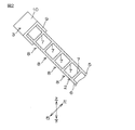
- FIG. 1 is a side view showing a first embodiment of the shielding plate of the present invention.
- FIG. 2 is a cross-sectional view taken along line AA shown in FIG.
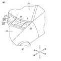
- FIG. 3 is a perspective view of a main part of the vehicle as an example of the vehicle structure including the shielding plate shown in FIG.
- FIG. 4 is a left side view of an essential part of the vehicle shown in FIG.
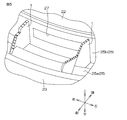
- FIG. 5 is a perspective view of the main part as seen from the upper left, showing a case where an external force is applied to the vehicle shown in FIG. 6 is an enlarged view of the left shielding plate shown in FIG.
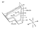
- FIG. 7 is a perspective view showing the second embodiment of the present invention as viewed from the upper left.
- FIG. 8 is a left side view showing the third embodiment of the present invention.
- FIG. 1 is a side view showing a first embodiment of the shielding plate of the present invention.
- FIG. 2 is a cross-sectional view taken along line AA shown in FIG.
- FIG. 3 is
- FIG. 9 is an explanatory view showing a method of attaching the elastic member to the peripheral edge in the fourth embodiment of the present invention, wherein (a) is a step of opening the tip of the fitting portion toward both sides in the thickness direction; (B) shows the process of sticking the front-end
- FIG. 10 is an explanatory view showing a method of attaching an elastic member to a peripheral edge portion in a fifth embodiment of the present invention, wherein (a) shows a pressure-sensitive adhesive layer on the inner surface of the elastic member, and a peripheral edge of a flat member. (B) shows the process which adhere
- FIG. 11 is a perspective view showing a sixth embodiment of the present invention.
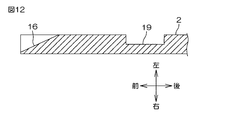
- 12 is a cross-sectional view of the first concave portion and the second concave portion of FIG. 11, and is a cross-sectional view taken along the line BB shown in FIG.
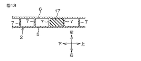
- FIG. 13 is a cross-sectional view of the filling portion of FIG. 11 and is a cross-sectional view taken along the line CC shown in FIG.
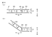
- FIG. 14 is a cross-sectional view of the bent portion of FIG. 11, and is a cross-sectional view taken along the line DD shown in FIG.
- FIG. 15 is a perspective view for explaining bending at the bent portion of FIG.
- FIG. 16 is a perspective view showing a bent portion according to the seventh embodiment of the present invention.
- FIG. 12 is a cross-sectional view of the first concave portion and the second concave portion of FIG. 11, and is a cross-sectional view taken along the line BB shown in FIG.
- FIG. 13 is a cross-section
- FIG. 17 is a perspective view showing a bent portion according to the eighth embodiment of the present invention.
- FIG. 18 is a perspective view showing a bent portion according to the ninth embodiment of the present invention.
- FIG. 19 is a cross-sectional view showing a bent portion according to the tenth embodiment of the present invention.
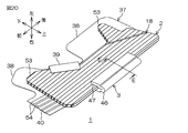
- FIG. 20 is a perspective view showing an eleventh embodiment of the present invention.
- FIG. 21 is an enlarged perspective view showing the flexure of FIG. 22 is an enlarged cross-sectional view of the elastic member of FIG. 20, and is a cross-sectional view taken along the line EE shown in FIG. FIG.
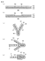
- Step 23 is an explanatory view showing a method for attaching the elastic member to the peripheral edge, where (a) is a step of preparing an elastic adhesive sheet, and (b) is to peel off the release film at the center in the width direction. Step (c) is a step of bonding the centers in the width direction to each other, (d) is a step of causing the sticking portion to face the peripheral edge of the flat plate member, and (e) is a step of attaching the sticking portion to the flat plate member. The process of sticking to a peripheral part is shown.
- FIG. 1 is a perspective view showing a first embodiment of the shielding plate of the present invention
- FIG. 2 is a partial sectional view taken along the line AA shown in FIG.
- standard when mentioning a direction regarding the shielding board 1, the direction when it fixes to a perpendicular direction is made into a reference
- the shielding plate 1 is mounted on the flat plate member 2, the elastic member 3 provided on the peripheral edge of the flat plate member 2 over the entire circumference, and the flat plate member 2, and is a space of the structural member.
- the clip 4 is provided as a fixing member that can be fixed to.
- the flat plate-like member 2 has a cross-sectional ladder shape (cross-sectional harmonica shape) and is opposed to the left side plate 5 and the left side plate 5 as the first flat plate with an interval in the left-right direction (horizontal direction).
- a right plate 6 as a second flat plate and a plurality of column portions 7 provided between the left plate 5 and the right plate 6 are integrally provided.
- the flat plate-like member 2 is formed in a predetermined shape corresponding to the cross-sectional shape of the space of a structural member to be described later.
- the rear side thereof has a substantially rectangular shape in side view extending along the vertical direction.
- the front side is formed in a substantially pentagonal shape in a side view projecting forward from the upper end portion on the rear side to the center portion in the vertical direction.
- the left side plate 5 and the right side plate 6 are formed in a flat plate shape corresponding to the outer shape of the flat plate member 2.
- a plurality of the column portions 7 are arranged in parallel across the entire surface of the flat plate member 2 with an interval in the front-rear direction (a direction orthogonal to the thickness direction of the flat plate member 2).
- Each column portion 7 is formed in a straight line so as to incline backward as it goes upward.
- the pillar part 7 is formed in the flat form extended along the left-right direction, as shown in FIG.
- the fragile portion 8 is formed along one direction (shown as a fragile portion forming direction F in FIG. 1) between the column portions 7 formed in a straight line.
- the flat plate member 2 is formed over the entire surface with an interval in a direction perpendicular to the fragile portion forming direction F.
- the flat plate-like member 2 is formed, for example, by synthetic extrusion such as polyethylene, polypropylene, polycarbonate, polyester, polystyrene, acrylic, etc., into a sheet shape having the above-mentioned cross-sectional shape by integral extrusion molding, and then the shape described above. It can be formed by punching. Preferably, it is formed from polypropylene or polycarbonate.
- the flat plate member 2 can be formed, for example, by punching a commercially available plastic cardboard sheet (dumpler sheet) into the shape described above.
- the basis weight of the flat plate member 2 is, for example, 200 to 2000 g / m 2 , preferably 300 to 1500 g / m 2 . If the basis weight of the flat member 2 is less than the above range, there is a problem that the strength of the flat member 2 becomes too low. Moreover, when there are more fabric weights of the flat member 2 than the said range, there exists a malfunction that the flat member 2 becomes difficult to bend.
- the vertical compressive strength in the direction in which the fragile portions of the flat plate member 2 are juxtaposed is, for example, 0.02 to 0.9 times the vertical compressive strength in the fragile portion forming direction F, preferably 0.05 to 0. 0. 5 times. If the vertical compressive strength in the direction in which the fragile portions of the flat plate member 2 are arranged side by side is lower than the above range, it may be difficult to maintain the shape of the flat plate member 2. Moreover, when the vertical compressive strength in the direction where the weak part of the flat member 2 is arranged in parallel is higher than the said range, it may become difficult to bend the flat member 2 along the intended direction.
- the vertical compression strength (end crush) is obtained in accordance with JIS Z 0403-2 in the above-described direction.
- the left side plate 5 and the right side plate 6 are opposed to each other with an interval of 0.8 to 10 mm, preferably 2 to 5 mm, for example, and their thickness is, for example, 0.1 to 1 mm, preferably 0. .2 to 0.6 mm.
- the column portions 7 are arranged in parallel at an interval of, for example, 0.8 to 10 mm, preferably 2 to 5 mm, and the thickness thereof is, for example, 0.1 to 1 mm, preferably 0.2 to 0.6 mm. It is.
- the column part 7 is arrange
- the column part 7 is arrange
- the elastic member 3 includes a fitting portion 9 that fits with the peripheral portion so as to sandwich the peripheral portion of the flat plate member 2, and an opposite side of the flat member 2 with respect to the fitting portion 9. And an elastic portion 10 to be arranged.
- the fitting portion 9 is formed in a substantially U-shaped cross section that opens toward the flat plate member 2 so as to correspond to the peripheral end portion of the flat plate member 2.
- fitting portion 9 examples include pressure-sensitive adhesive sheets, pressure-sensitive adhesive films and rigid molded products formed from synthetic resins such as polyethylene, polypropylene, polyvinyl chloride, polyester, nylon, polyurethane, and epoxy, and ethylene / propylene rubber foams. And an adhesive sheet formed from a synthetic rubber foam such as ethylene / propylene / diene rubber foam.
- an adhesive sheet formed from a synthetic rubber foam such as ethylene / propylene / diene rubber foam.
- the adhesive sheet formed from a synthetic rubber foam is mentioned. More preferably, an adhesive sheet formed from an ethylene / propylene / diene rubber foam is used.
- the elastic part 10 is formed in a substantially rectangular shape in sectional view.
- the elastic portion 10 is formed of, for example, a synthetic rubber foam such as a polyurethane rubber foam, an ethylene / propylene rubber foam, an ethylene / propylene / diene rubber foam, or preferably an ethylene / propylene / diene rubber foam.
- the elastic member 3 is formed by adhering the elastic portion 10 to the fitting portion 9 with an adhesive or the like.
- the clip 4 is formed of, for example, a hard synthetic resin molded product or the like. As shown in FIG. 1, the clip 4 is used to fix the flat plate member 2 and the elastic member 3 in the space between the holding member 11 and the structural member from the left and right directions.
- the fixed portions 12 are integrally provided, and are arranged one by one below the front side and the rear side of the flat plate-like member 2.
- the sandwiching portion 11 is integrally provided with a bottom portion 13 having a substantially rectangular shape in plan view and two sandwiching pieces 14 extending upward from both left and right end edges of the bottom portion.
- the length of the bottom 13 in the left-right direction is, for example, 2 to 18 mm, preferably 4 to 12 mm.
- the thickness of the bottom portion 13 is, for example, 0.5 to 5 mm, preferably 1 to 3 mm, and the thickness of the sandwiching piece 14 is, for example, 0.5 to 3 mm, preferably 1 to 2 mm.
- the fixed portion 12 is formed in a substantially cylindrical shape so as to protrude downward from the lower end surface of the bottom portion 13. Moreover, the radial direction length of the fixing
- the fitting portion 9 of the elastic member 3 is folded and adhered so as to sandwich the peripheral edge portion of the flat plate member 2 formed in a predetermined shape, and then the clip 4. The flat plate member 2 and the elastic member 3 are sandwiched by the sandwiching pieces 14 until the elastic member 3 comes into contact with the bottom portion 13. In this way, the shielding plate 1 is obtained.
- FIG. 3 is a perspective view of a main part when a cowl portion of a vehicle as an example of a vehicle structure including the shielding plate shown in FIG. 1 is viewed from the upper left.
- FIG. 4 is a left side view of an essential part of the vehicle shown in FIG. In FIG. 3, for convenience, the inside of the cowl portion 24 is directly displayed, and the elastic member 3 of the shielding plate 1 is omitted.
- the vehicle 21 includes a windshield 22, an engine hood 23, and a cowl portion 24 provided between the windshield 22 and the engine hood 23.
- the cowl portion 24 is disposed along the left-right direction of the vehicle 21 and includes a cowl frame 25 having a structure that is recessed downward.
- the cowl frame 25 is integrally provided with an engine room side groove portion 25a formed on the front side and a vehicle interior side groove portion 25b that communicates with the rear side of the engine room side groove portion 25a and is formed deeper.
- a cowl space 26 as an example of a space of a structural member is defined by the side groove portion 25a and the vehicle interior side groove portion 25b.
- an outside air introduction port 27 for introducing outside air into the passenger compartment is formed in the rear wall of the passenger compartment side groove 25b.
- the bottom walls of the engine compartment side groove portion 25a and the vehicle compartment side groove portion 25b are provided with fixing portions at positions corresponding to the clips 4 disposed on the front side and the rear side of the shielding plate 1, respectively, as shown in FIG.
- An insertion hole 28 is formed.
- the shielding board 1 is arrange
- the fixing portion 12 of the front clip 4 is fixed to the fixing portion insertion hole 28 of the engine room side groove portion 25a.
- the portion 12 is inserted from above into the fixed portion insertion hole 28 of the engine room side groove portion 25b until the lower end surface of the bottom portion 13 comes into contact with the bottom surface of the cowl frame 25, and the elastic member 3 is in close contact with the inner peripheral surface of the cowl frame 25.
- the portion where the outside air introduction port 27 is formed is shielded, and hot air and odor from the engine room can be prevented from flowing into the vehicle interior via the outside air introduction port 27. it can.
- the operation of the shielding plate 1 when an impact force I as an external force is applied to the vehicle 21 will be described with reference to FIGS. 5 and 6.
- the direction in which the impact force I is applied is, for example, that the vehicle 21 collides head-on and the collided object comes on the engine hood 23 and the cowl portion 24 of the vehicle 21. This is assumed.
- FIG. 5 is a perspective view of the main part as seen from the upper left, showing a case where an external force is applied to the vehicle shown in FIG. 6 is an enlarged view of the left shielding plate shown in FIG.
- the shielding plate 1 is bent when an impact force I is applied to the vehicle 21. Specifically, first, an impact force I is applied from a direction substantially orthogonal to the weakened portion forming direction F, that is, from a diagonally upper front side (see FIG. 1).
- a stress is generated in the flat plate member 2 according to the impact force I, and the generated stress corresponds to the way the impact force I is applied (the magnitude, direction, applied portion, etc. of the impact force). It concentrates on any part of the member 2. Since the fragile portion 8 is formed over the entire surface of the flat plate member 2, as shown in FIG. 6, in the fragile portion 8 where stress is particularly concentrated, either the left side plate 5 or the right side plate 6 is in the left-right direction. By bending, the flat plate member 2 is bent.
- the flat plate-like member 2 is bent along the fragile portion forming direction F so that the right side plate 6 between the column portions 7 protrudes leftward at the fragile portion 8 on the front side thereof,
- the fragile portion 8 on the rear side is bent along the fragile portion forming direction F so that the left side plate 5 between the column portions 7 protrudes rightward, thereby bending at the two fragile portions 8. is doing.
- the flat member 2 is bent at the fragile portion 8 corresponding to the impact force I, and the impact force I can be absorbed.
- the weak part 8 bent by the impact force I is formed over the whole surface of the flat member 2, the weak part 8 is applied to any part where the impact force I is applied.
- the flat plate member 2 can be bent.
- the fragile portion 8 is provided over the entire surface of the flat plate member 2, the impact force I can be applied to the fragile portion 8 regardless of the shape of the flat plate member 2.
- the shielding plate 1 can reliably absorb the impact force I and can improve the production efficiency.
- the flat plate member 2 is formed of the left side plate 5, the right side plate 6 and the column part 7, and the fragile part 8 is formed between the column parts 7. In the portion 7, the strength of the shielding plate 1 can be maintained, and the flat member 2 can be reliably bent in the fragile portion 8 between the column portions 7.
- the fragile portion 8 is formed along the fragile portion forming direction F. Therefore, the flat plate-like member 2 can be reliably bent along the fragile portion forming direction F at the site where the impact force I is applied. As a result, the shielding plate 1 can absorb the impact force I more reliably.
- the plurality of weak parts 8 are arranged in parallel in the direction perpendicular to the weak part forming direction F. Therefore, the flat plate-like member 2 can be bent in the direction orthogonal to the fragile portion forming direction F regardless of the portion to which the impact force I is applied.
- the shielding plate 1 can absorb the impact force I more reliably.
- the vertical compressive strength in the direction in which the fragile portions 8 are arranged side by side is 0.02 to 0.9 times the vertical compressive strength in the fragile portion forming direction F. That is, the vertical compressive strength in the direction in which the fragile portions 8 are arranged side by side is set lower than the vertical compressive strength in the fragile portion forming direction F. Therefore, for example, when the vehicle 21 collides head-on and the collided object is placed on the engine hood 23 and the cowl portion 24 of the vehicle 21, the impact force from the direction in which the fragile portions 8 are arranged side by side. By adding I, the flat plate member 2 can be easily bent.
- this shielding board 1 can absorb more reliably the impact force I from the direction where the weak part 8 is arranged in parallel.
- the elastic member 3 is disposed on the peripheral edge of the flat plate member 2 over the entire circumference. Therefore, when the shielding plate 1 is attached to the cowl space 26, the elastic member 3 is deformed according to the shape of the cowl space 26 and is in close contact with the cowl frame 25.
- the shielding plate 1 can be brought into close contact with the cowl frame 25 with a simple configuration to improve the shielding effect.
- the elastic member 3 is arranged on the opposite side of the flat plate member 2 with respect to the fitting portion 9 that fits the peripheral portion so as to sandwich the peripheral portion of the flat plate member 2.
- the elastic part 10 is provided.
- the elastic member 3 can be reliably fixed to the flat plate member 2 by sandwiching the peripheral edge portion of the flat plate member 2 with the fitting portion 9, and when the shielding plate 1 is attached to the cowl space 26.
- the elastic part 10 can be securely attached to the cowl frame 25.
- the shielding plate 1 is provided with a clip 4 that can be fixed to the cowl space 26 on the flat plate member 2. Therefore, the shielding plate 1 can be installed in the cowl space 26 without separately forming the clip 4.
- FIG. 7 is a perspective view showing the second embodiment of the present invention as viewed from the upper left.
- members similar to those in the first embodiment are denoted by the same reference numerals as those in the first embodiment, and description thereof is omitted.
- the shielding plate 1 includes the clip 4 that can be fixed to the cowl space 26.
- the cowl frame 25 has a front wall and a rear wall.
- the clip 4 may not be provided.
- two first protrusions 34 are formed on the bridging plate 32 at intervals in the front-rear direction.
- the shielding plate 31 includes a flat plate member 2 and an elastic member 3.
- two through holes 33 are formed in the shielding plate 31 at substantially the center of the flat plate member 2 in an arrangement corresponding to the first protrusions 34.
- the shielding plate 31 is attached, for example, by inserting the first projecting portion 34 toward the left side through the through hole 33 and fixing the first projecting portion 34 to the bridge plate 32 on the right side.
- FIG. 8 is a left side view showing the third embodiment of the present invention.
- the same members as those in the first embodiment are denoted by the same reference numerals as those in the first embodiment, and the description thereof is omitted.
- the shielding plate 1 includes the straight column portions 7 that are arranged in parallel at intervals.
- the side view is arranged in a staggered manner.
- a substantially circular column portion 42 may be provided. And between each pillar part 42, it is divided as the weak part 43 weaker than the part in which the pillar part 42 is formed.
- the fragile portion 43 includes three fragile portions in the front-rear direction, the direction inclined backward as it goes upward, and the direction inclined forward as it goes upward between the column portions 42 arranged in a staggered manner. It is formed along the forming direction F. Moreover, each weak part formation direction F cross
- This shielding board 41 has the same effect as the shielding board 1 of 1st Embodiment. Moreover, in the shielding plate 41, the fragile portions 43 are formed along the three fragile portion forming directions F, and are arranged side by side in a direction orthogonal to the respective fragile portion forming directions F. Therefore, the flat plate member 2 can be bent in any direction regardless of the portion to which the impact force I is applied.
- FIG. 9 is an explanatory diagram showing a method of attaching the elastic member to the peripheral edge in the fourth embodiment of the present invention.
- the same members as those in the above-described embodiments are denoted by the same reference numerals, and the description thereof is omitted.
- the elastic member 3 is formed of separate members of the fitting portion 9 and the elastic portion 10, but for example, as shown in FIG. It can be formed from one member.
- the elastic layer 44 is formed from the foam forming the elastic portion 10 described above, and the elastic portion 10 having a substantially rectangular cross section as a base and the fitting portion 9 having a substantially U-shaped cross section as a free portion. Is formed integrally.
- An adhesive layer 45 made of a known adhesive is laminated on the inner surface of the fitting portion 9. And in order to stick this elastic member 3 to the peripheral part of the flat member 2, first, as shown by the broken line arrow of FIG. Open to both sides. Subsequently, as shown in the arrow in FIG. 9A and FIG. 9B, after the fitting portion 9 is inserted into the flat plate member 2, the inner surface of the fitting portion 9 is interposed via the adhesive layer 45. It sticks to the peripheral part of the flat member 2.
- FIG. 10 is an explanatory view showing a method of attaching the elastic member to the peripheral edge in the fifth embodiment of the present invention.
- the elastic part 10 and the fitting part 9 are formed in a substantially rectangular cross section and a substantially U-shaped cross section, respectively.
- the elastic part 10 and the fitting part 9 are formed in a substantially rectangular cross section and a substantially U-shaped cross section, respectively.
- FIG. 3 can also be formed in a trapezoidal cross section.
- the elastic member 3 is formed in a substantially trapezoidal shape in cross-section in which the width (length in the thickness direction of the flat plate-like member 2) is gradually narrowed toward the outside (outside of the peripheral edge).
- the adhesive layer on the inner surface of the elastic member 3 opposite surface facing the peripheral portion. 45 is brought into contact with the peripheral edge of the flat plate member 2.
- the center in the width direction of the inner surface of the elastic member 3 is bonded to the end surface of the peripheral portion of the flat plate member 2 via the adhesive layer 45.
- both end portions in the width direction of the elastic member 3 are bonded to both the left side surface and the right side surface of the peripheral portion of the flat plate member 2 through the adhesive layer 45.
- the adhesive layer 45 Adhere to both sides of the periphery.
- the elastic member 3 is formed into a substantially circular cross section (curved shape that bulges outward) by pulling at both ends in the width direction as described above, and an elastic portion 10 disposed outside the peripheral portion, The fitting parts 9 arranged on both sides of the part are respectively formed.
- the elastic member 3 Since the elastic member 3 is formed in a substantially circular cross section (curved cross section) after being attached to the peripheral portion, the elastic member 3 is compared with the substantially rectangular elastic member 3 in FIG. The peeling due to the contact with the cowl portion 24 can be effectively prevented. Therefore, the adhesion between the elastic member 3 and the peripheral edge of the flat plate member 2 can be enhanced. As a result, the shielding effect of the shielding plate 1 using the elastic member 3 can be further improved.
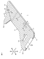
- FIG. 11 is a perspective view showing a sixth embodiment of the present invention
- FIG. 12 is a cross-sectional view of the recess shown in FIG. 11, and is a cross-sectional view taken along line BB shown in FIG. 11 is a cross-sectional view taken along line CC shown in FIG. 11, and
- FIG. 14 is a cross-sectional view of the bent portion shown in FIG. 11, and is DD shown in FIG.
- FIG. 15 is a cross-sectional view taken along the line, and FIG. 15 is a perspective view for explaining bending at the bent portion of FIG.
- the shielding plate 1 shown in FIG. 11 is applied in an appropriate posture corresponding to the shape of the cowl of the vehicle structure. For convenience, the direction arrow shown in FIG. Will be described.
- the shielding plate 1 has a cross-section (cross-section in a direction perpendicular to the front-rear direction) ladder shape, is a substantially rectangular flat strip shape extending in the front-rear direction, and the lower end of the front end and the lower end of the rear end are on the lower side
- the flat plate-like member 2 having the second projecting portions 53 projecting from each other is provided.
- the flat plate-like member 2 includes a first concave portion 16, a second concave portion 19 and a filling portion 17 as reinforcing portions, and a bent portion 18.
- the first recess 16 is partially formed on the flat plate member 2, specifically, provided on the front end surface of the flat plate member 2 and formed so that the left side of the front end edge is compressed in an inclined manner. Yes. Specifically, as shown in FIG. 11 and FIG. 12, the first recess 16 is formed in an inclined shape (triangular cross section) that approaches the right side as the left side moves forward. Moreover, the 1st recessed part 16 can be formed by hot-pressing the front-end surface of the flat member 2 from the upper side, for example.
- the second recess 19 is partially formed on the flat plate member 2. Specifically, the second recess 19 is provided at the front end portion of the flat plate member 2, and is arranged behind the first recess 16 with an interval therebetween. It is formed so as to extend along a direction (a direction orthogonal to the fragile portion forming direction F). Moreover, the 2nd recessed part 19 is formed so that the left side part of the flat member 2 may be compressed toward the right side (in the thickness direction middle). Specifically, the second recess 19 is formed to be recessed in a substantially rectangular shape in cross section.
- the 2nd recessed part 19 can be formed by hot-pressing the left side of the flat member 2 from the left side, for example.
- the filling portion 17 is partially formed on the flat plate member 2. Specifically, the filling portion 17 is arranged on the upper portion of the flat plate member 2, and in the flat plate member 2 in the front-rear direction. Is formed over.
- the filling portion 17 is formed by filling a space (filling space) defined by a pair of column portions 7 facing each other, the left side plate 5 and the right side plate 6 on which they are installed, with a filler.
- a filler which forms the filling part 17 the same thing as the above-mentioned synthetic resin which forms the flat member 2, and / or the above-mentioned synthetic rubber foam is mentioned, for example.
- the filling portion 17 can be formed by injecting the above-described synthetic resin into the above-described filling space from the front end and / or the rear end thereof.
- the bent portion 18 is partially formed on the flat plate member 2, and is specifically provided at the rear end portion of the flat plate member 2. It is formed so as to be inclined with respect to the forming direction F. That is, the bent portion 18 is formed in a straight line shape from the rear end surface to the lower end surface in a side view, and is inclined downward toward the front.
- the bent portion 18 is formed so that the left side portion of the flat plate member 2 (the left side plate 5 and the column portion 7 indicated by a broken line in FIG. 14) is compressed toward the right side (in the thickness direction).
- the bent portion 18 is formed to be recessed in a substantially triangular shape in cross section.
- the bending part 18 is formed so that bending is possible along the above-mentioned inclination direction (direction where the bending part 18 extends) so that the arrow of FIG.14 (b) may be referred.
- the bending part 18 can be formed by pressing the left side of the flat member 2 from the left side, for example.
- the bent portion 18 is formed as a portion that is bent when an external force (stress) is applied by an operator described later.
- the shielding plate 1 when the impact force I is applied to the front end portion of the flat plate member 2 along the fragile portion forming direction F, the flat plate member 2 attempts to bend, and the first recess 16 and the first The two recesses 19 can reinforce them and their vicinity. Therefore, the strength of such a part can be increased. As a result, it is possible to absorb the impact force I by bending the flat plate member 2 while maintaining a predetermined shape.
- the operator or the like bends the bent portion 18 to ensure that the shielding plate 1 is secured to the cowl portion. 24. Specifically, when there is a narrow space in front of the place where the shielding plate 1 is disposed, the bent portion 18 is bent, and after passing through the narrow space in a state where the flat plate member 2 is folded, the bent portion is again formed. By extending 18, the flat plate-like member 2 is arranged in an open state.
- the bent portion 18 is formed to be inclined with respect to the fragile portion forming direction F.
- a virtual line in FIG. It can also be formed into a shape.
- the bent portion 18 is formed in an inclined shape with respect to the fragile portion forming direction F.
- the bent portion 18 When the bent portion 18 is formed perpendicular to the fragile portion forming direction F, as shown in FIG.
- the end portions 29 facing the bent portion 18 are arranged to face each other in the fragile portion forming direction F. For this reason, the end portions 29 come into contact with each other when the bent portion 18 is bent, so that the movable range of bending of the bent portion 18 may be limited, and the right side plate 6 of the bent portion 18 is pulled by the contact described above. And the right side plate 6 may be damaged.
- the end portion 29 desired for the bent portion 18 of the installation portion 20 is in a direction G perpendicular to the direction along the bent portion 18. They are not arranged opposite to each other but are arranged in a bowl shape. Therefore, the end portions 29 on both sides of the bending portion 18 are close to each other while preventing the end portions 29 of the erection portion 20 from contacting each other when the bending portion 18 is bent (see FIG. 14B).
- the bent portion 18 can be flexibly bent, and damage (specifically, cracking, etc.) of the right side plate 6 of the bent portion 18 can be prevented.
- FIG. 16 is a perspective view showing a bent portion according to a seventh embodiment of the present invention
- FIG. 17 is a perspective view showing a bent portion according to an eighth embodiment of the present invention
- FIG. 18 is a view of the ninth embodiment of the present invention.
- FIG. 19 is sectional drawing which shows the bending part of 10th Embodiment of this invention.
- the bent portion 18 is formed so as to be cut out in a triangular shape in cross section, but the shape is not particularly limited.
- FIGS. It can also be formed in a shape (FIGS. 16, 18 and 19) and a substantially W-shaped cross-sectional view (FIG. 17) so as to be recessed.
- the bent portion 18 is formed in a straight line extending orthogonally to the fragile portion forming direction F. Further, the width (length in the front-rear direction) of the bent portion 18 is a length that does not cause contact between the end portions 29 of the erection portion 20 when bent, that is, between the left side plate 5 and the right side plate 6 described above. It is set longer than the interval.
- the bent portion 18 is formed along the vertical direction and is formed so as to be bendable along the vertical direction.
- the bending part 18 can be formed by hot-pressing the left side part of the flat member 2 from the left side, for example. Thereby, the flexible bending of the bending part 18 can be achieved. Therefore, when a flow of liquid (specifically, rainwater and / or cleaning liquid, etc.) and / or a solid foreign substance flowing therewith occurs in the cowl space 26 (see FIG. 3) of the cowl portion 24, it is caused by that.
- the flat plate member 2 can be bent by the pressing force, and the liquid and / or foreign matter flowing in the cowl space 26 (see FIG. 3) in the cowl portion 24 of the vehicle 21 can be passed.
- the bent portion 18 is partitioned by two substantially triangular compression portions 50.
- the bent portion 18 can achieve a more flexible bend by the two compressed portions 50. Therefore, the liquid and / or foreign matter flowing through the cowl space 26 (see FIG. 3) in the cowl portion 24 of the vehicle 21 can be more reliably passed.
- streaks 30 that are inclined with respect to the vertical direction are formed on the left side surface and the right side surface of the bent portion 18. That is, among the streaks 30, the left streak 51 formed on the left side surface of the bent portion 18 and the right streak 52 formed on the right side surface of the bent portion 18 protrude to the left side and the right side, respectively, and are spaced apart in the vertical direction. A plurality are arranged with a gap therebetween. Further, the left streak 51 and the right streak 52 are orthogonal to each other when projected in the left-right direction (thickness direction), more specifically, while the left streak 51 is inclined backward as it goes upward, The right streak 52 is inclined forward as it goes upward.
- the streak 30 is formed by applying heat and pressure simultaneously from the left and right directions by a heat press in the left and right direction, specifically, a heat press machine having two molds corresponding to the left streak 51 and the right streak 52. .
- a heat press machine having two molds corresponding to the left streak 51 and the right streak 52.
- the bendability of the bent portion 18 can be enhanced by the streak 30. Therefore, the liquid and / or foreign matter flowing through the cowl space 26 (see FIG. 3) in the cowl portion 24 of the vehicle 21 can be reliably passed.
- the bent portion 18 is formed over the entire vertical direction of the flat plate member 2, but can also be formed, for example, in the vertical direction end portion or in the middle of the direction.
- the flat plate member 2 is formed with slits 35 for dividing the flat plate member 2 into two, and the first flexible sheet 36 is provided on the left side of the flat plate member 2 on both sides of the slit 35.
- a bent portion 18 is formed.
- the first flexible sheet 36 is formed from, for example, the above-described synthetic resin, for example, synthetic rubber such as ethylene / propylene rubber, ethylene / propylene / diene rubber, foam, etc., and is made of paper, nonwoven fabric, woven fabric, etc. It is made of fiber.
- the first flexible sheet 36 can achieve flexible bending of the bent portion 18, and the liquid flowing into the cowl space 26 (see FIG. 3) in the cowl portion 24 of the vehicle 21 and / or Or a foreign material can be passed.
- FIG. 20 is a perspective view showing an eleventh embodiment of the present invention
- FIG. 21 is an enlarged perspective view showing a flexible portion of FIG. 20
- FIG. 22 is an enlarged sectional view of the elastic member of FIG.
- FIG. 23 is an explanatory view showing a method of attaching the elastic member to the peripheral edge portion.
- the shielding plate 1 further includes a second flexible sheet 37 as a flexible sheet.
- the second flexible sheet 37 is laminated on the right side surface of the flat plate member 2, and specifically, is disposed so as to include the second protruding portion 53 of the flat plate member 2 in a side view. . That is, the second flexible sheet 37 includes an extending portion 38 that extends outward (forward, backward, and downward) from the peripheral edge of the second protrusion 53 of the flat plate-like member 2.
- the second flexible sheet 37 is formed of, for example, the same material as that for forming the first flexible sheet 36, and is preferably formed of the above-described synthetic rubber.
- the second flexible sheet 37 includes a bent portion 39 and a bellows portion 40.
- the bending portion 39 is bent toward the left side in the extending direction of the extending portion 38, and the distal end portion of the extending portion 38 is placed on the left side of the peripheral portion of the flat plate member 2. It is formed by adhering to the surface via an adhesive (not shown).
- the bellows portion 40 extends forward from the front end portion, and is formed in a cross-sectional bellows shape.
- the accordion portion 40 is formed with fold lines 54 extending in the front-rear direction at intervals in the up-down direction.
- the elastic member 3 includes the elastic layer 44 and the adhesive layer 45 as described above, and includes an overlapping portion 46 and a pasting portion 47 integrally.
- the overlapping portion 46 is disposed on the outer side (upper side) of the peripheral edge portion of the flat plate-like member 2, and is partitioned as a portion that overlaps each other when the elastic layer 44 is bonded to each other through the adhesive layer 45.
- the sticking portion 47 is continuous from the lower end portion of the overlapping portion 46, and is adhered to the left side surface and the right side surface of the peripheral portion of the flat plate member 2 via the adhesive layer 45, whereby the peripheral edge of the flat plate member 2 is obtained. It is divided as a part stuck on the both sides
- a cut 58 is formed in advance between the center in the width direction and both ends in the width direction.
- the release film 57 at the center in the width direction is peeled off from the adhesive layer 45 along the cut line 58.
- the elastic layer 44 at the center in the width direction is bonded via the pressure-sensitive adhesive layer 45 so that they overlap each other. Thereby, the overlap part 46 and the sticking part 47 which continues from it and extends in two directions are formed.
- the release film 57 of the sticking portion 47 is peeled off from the pressure-sensitive adhesive layer 45, and the elastic layer 44 of the sticking portion 47 is end-faced at the peripheral edge of the flat plate member 2.
- the elastic layer 44 of the attaching portion 47 is attached to the left side surface and the right side surface of the peripheral portion via the adhesive layer 45.
- the flexible extending portion 38 can be reliably attached to the cowl portion 24 (see FIG. 3) to which the shielding plate 1 is attached.
- the shielding plate 1 can be reliably arranged on the cowl portion 24 having a complicated shape, or the flexible extension portion 38 is left and right.
- the liquid and / or foreign matter described above in the cowl space 26 (see FIG. 3) of the cowl portion 24 can be passed.
- the overlapping portion 46 can be fixed to the flat plate member 2 by the sticking portion 47, and the overlapping portion 46 can be securely attached to the cowl portion 24.
- the overlap width W (see FIG. 22) of the overlap portion 46 can be set to a constant value, the shielding effect by the overlap portion 46 can be further enhanced. Furthermore, in arrangement
- the shielding plate is used for, for example, a space partition such as a cowl member of a vehicle.
Landscapes
- Engineering & Computer Science (AREA)
- Chemical & Material Sciences (AREA)
- Combustion & Propulsion (AREA)
- Transportation (AREA)
- Mechanical Engineering (AREA)
- Architecture (AREA)
- Structural Engineering (AREA)
- Body Structure For Vehicles (AREA)
- Vehicle Interior And Exterior Ornaments, Soundproofing, And Insulation (AREA)
- Vibration Dampers (AREA)
Abstract
Description
通常、このエアボックス内に取り込んだ外気を、カウルトップカバーに開口された通気孔を通じて車室内に流入させることにより、車室内を換気するが、このとき、エンジンルームの熱気や臭気が車室内へ流入するという不具合がある。
例えば、車体パネル、フェンダパネルおよびフェンダプロテクタにより形成される空間部内の空気の流通を遮断するために、車体パネルにインシュレータを取り付ける場合において、インシュレータの取り付け手段に、フェンダパネルに加わる衝撃力により破断する破断部を設ける、インシュレータの取り付け構造が提案されている(例えば、下記特許文献1参照。)。
一方、上記の構造では、破断部は、取り付け手段の特定部位に設けられているところ、衝突時の衝撃が、その特定部位に十分に加わらないと、破断部が破断しない場合がある。そのような場合には、インシュレータがフェンダパネルから脱離しないため、フェンダパネルが変形しにくくなり、衝撃を吸収しにくいという不具合がある。
そこで、本発明の目的は、外力が加わる部位に関わらず屈曲して、衝撃を確実に吸収することができ、しかも、形状に関わらず生産効率を向上させることができる遮蔽板、および、その遮蔽板を備える車両構造を提供することにある。
この遮蔽板では、外力が加わることによって屈曲する応力集中部が、平板状部材の全面にわたって形成されている。そのため、外力がどの部位に加わっても応力集中部において、平板状部材を屈曲させることができる。しかも、応力集中部が平板状部材の全面にわたって設けられているので、平板状部材をどのような形状に形成しても、外力を応力集中部に作用させることができる。
また、本発明の遮蔽板では、前記平板状部材は、第1平板、第1平板と対向配置される第2平板、および、第1平板と第2平板との間に架設される複数の柱部を備え、前記応力集中部は、前記柱部の間に形成される脆弱部であることが好適である。
そのため、柱部において、遮蔽板の強度を保つことができるとともに、柱部の間の脆弱部において、平板状部材を確実に屈曲させることができる。
また、本発明の遮蔽板では、前記平板状部材には、少なくとも一方向に沿って、前記脆弱部が形成されることが好適である。
その結果、この遮蔽板は、衝突時の衝撃を、より確実に吸収することができる。
また、本発明の遮蔽板では、前記平板状部材には、前記脆弱部が形成される方向と直交する方向に間隔を隔てて、複数の前記脆弱部が並設されることが好適である。
その結果、この遮蔽板は、衝突時の衝撃を、より確実に吸収することができる。
また、本発明の遮蔽板では、前記平板状部材には、3方向に沿って、それぞれ前記脆弱部が形成され、3方向とそれぞれ直交する方向に間隔を隔てて、複数の前記脆弱部が並設されることが好適である。
その結果、この遮蔽板は、衝突時の衝撃を、より一層確実に吸収することができる。
また、本発明の遮蔽板では、前記脆弱部が並設される方向における垂直圧縮強さが、前記脆弱部が形成される方向における垂直圧縮強さの0.02~0.9倍であることが好適である。
また、本発明の遮蔽板では、前記平板状部材に部分的に形成される補強部をさらに備えることが好適である。
この遮蔽板では、補強部によって、所望の部位を補強することができる。そのため、所望の部位の強度を向上させることができる。
この遮蔽板では、平板状部材の所望の部位を屈曲させることができる。
また、本発明の遮蔽板では、前記屈曲部は、一方向に沿うように形成されており、構造部材への実装時、および/または、前記構造部材の空間に液体および/または固体の流れが生じた時、前記一方向に沿って屈曲可能であることが好適である。
あるいは、平板状部材を屈曲させることにより、構造部材の空間における液体および/または固体を通過させることができる。
また、本発明の遮蔽板では、前記屈曲部は、前記平板状部材の厚み方向における熱プレスにより形成され、前記屈曲部の一方面および他方面には、前記一方向に対して傾斜状に沿う筋目が形成されており、前記屈曲部の一方面の前記筋目と、前記屈曲部の他方面の前記筋目とは、厚み方向に投影したときに交差していることが好適である。
また、本発明の遮蔽板では、前記平板状部材の周縁部の少なくとも一部に弾性部材が設けられていることが好適である。
その結果、この遮蔽板を、簡易な構成で、構造部材に密着させて、遮蔽効果を高めることができる。
この遮蔽板では、弾性部材が、周縁部を挟むように周縁部と嵌合する嵌合部と、嵌合部に対して平板状部材の反対側に配置される弾性部とを備えている。
また、本発明の遮蔽板では、前記弾性部材は、弾性層および前記弾性層の表面に形成される粘着剤層を備え、前記弾性部材は、前記周縁部の外側に配置され、前記弾性層が前記粘着剤層を介して互いに接着されることにより重なる重なり部分と、前記重なり部分から連続し、前記周縁部の一方面および他方面に接着されることにより前記周縁部に貼着される貼着部分とを備えていることが好適である。
また、本発明の遮蔽板では、前記平板状部材の少なくとも一方面に積層され、前記平板状部の周縁部から外方に延出する延出部を備える可撓性シートをさらに備えていることが好適である。
一方、可撓性の延出部を屈曲させることにより、遮蔽板を、複雑な形状の構造部材に確実に配置することができながら、あるいは、可撓性の延出部を屈曲させることにより、構造部材の空間における液体および/または固体を通過させることができながら、構造部材の空間を確実に遮蔽することができる。
この遮蔽板は、構造部材の空間に固定可能な固定部材が、平板状部材に備えられている。そのため、別途、固定部材を形成しなくても、遮蔽板を構造部材の空間に設置することができる。
また、本発明の車両構造は、平板状部材と、前記平板状部材の全面にわたって形成され、外力が加わることによって屈曲する応力集中部とを備える遮蔽板を備えることを特徴としている。
そのため、この車両構造は、衝突時に、衝撃を確実に吸収することができる。
また、本発明の車両構造によれば、衝突時に、衝撃を確実に吸収することができる。
遮蔽板1は、図1に示すように、平板状部材2、平板状部材2の周縁部に全周にわたって設けられている弾性部材3、および、平板状部材2に装着され、構造部材の空間に固定可能な固定部材としてのクリップ4を備えている。
平板状部材2は、図1に示すように、後述する構造部材の空間の断面形状に対応するような所定形状に形成され、例えば、その後側が、上下方向に沿って延びる側面視略矩形状に形成され、その前側が、その後側の上端部から上下方向中央部にわたって、前方に突出する側面視略五角形状に形成されている。
柱部7は、平板状部材2の全面にわたって、前後方向(平板状部材2の厚み方向と直交する方向)に間隔を隔てて複数並列配置されている。各柱部7は、上方に向かうに従って後方に傾斜するように、一直線状に形成されている。また、柱部7は、図2に示すように、左右方向に沿って延びる平板状に形成されている。
すなわち、脆弱部8は、一直線状に形成される各柱部7の間において、一方向(図1において、脆弱部形成方向Fとして示す。)に沿って形成されており、各脆弱部8は、脆弱部形成方向Fと直交する方向に間隔を隔てて、平板状部材2の全面にわたって形成されている。
平板状部材2の目付けは、例えば、200~2000g/m2、好ましくは、300~1500g/m2である。平板状部材2の目付けが上記範囲より少ないと、平板状部材2の強度が低くなりすぎるという不具合がある。また、平板状部材2の目付けが上記範囲より多いと、平板状部材2が屈曲しにくくなるという不具合がある。
左側板5と右側板6とは、例えば、0.8~10mm、好ましくは、2~5mmの間隔を隔てて対向配置され、それらの厚みは、例えば、0.1~1mm、好ましくは、0.2~0.6mmである。
嵌合部9は、平板状部材2の周端部に対応するように、平板状部材2に向かって開く断面略コ字状に形成されている。
そして、弾性部材3は、嵌合部9に弾性部10を接着剤などにより接着することにより形成される。
挟持部11は、平面視略矩形状の底部13と、底部の左右方向両端縁から上方に向かって延びる2枚の挟持片14とを一体的に備えている。底部13の左右方向長さは、例えば、2~18mm、好ましくは、4~12mmである。また、底部13の厚みは、例えば、0.5~5mm、好ましくは、1~3mmであり、挟持片14の厚みは、例えば、0.5~3mm、好ましくは、1~2mmである。
そして、遮蔽板1を製造するには、まず、所定形状に形成された平板状部材2の周縁部を挟むように、弾性部材3の嵌合部9を折り曲げて貼着し、次いで、クリップ4の挟持片14で平板状部材2および弾性部材3を、底部13に弾性部材3が当接するまで挟み込む。これによって、遮蔽板1を得る。
以下、図1に示される遮蔽板1の使用方法について、車両構造の一例としての車両21のカウル部24に適用する例を挙げて説明する。
図3は、図1に示される遮蔽板を備えた車両構造の一例としての車両のカウル部を左上方から見た要部斜視図である。図4は、図3に示される車両の要部左側面図である。なお、図3では、便宜的に、カウル部24の内部を直接表示しており、また、遮蔽板1の弾性部材3を省略している。
カウル部24は、車両21の左右方向に沿って配置されており、下方に向かって凹む構造のカウルフレーム25を備えている。カウルフレーム25は、前側に形成されるエンジンルーム側溝部25a、および、エンジンルーム側溝部25aの後側に連通し、より深く形成される車室側溝部25bを一体的に備えており、エンジンルーム側溝部25aと車室側溝部25bとにより、構造部材の空間の一例としてのカウル空間26が区画されている。また、車室側溝部25bの後壁には、外気を車室内に導入するための外気導入口27が形成されている。また、エンジンルーム側溝部25aおよび車室側溝部25bの底壁には、図4に示すように、遮蔽板1の前側および後側に配置されているクリップ4にそれぞれ対応する位置において、固定部挿通穴28が形成されている。
遮蔽板1をカウル空間26に配置するには、図4に示すように、前側のクリップ4の固定部12を、エンジンルーム側溝部25aの固定部挿通穴28に、後側のクリップ4の固定部12を、エンジンルーム側溝部25bの固定部挿通穴28に、底部13の下端面がカウルフレーム25の底面に当接するまで上方から挿通し、弾性部材3がカウルフレーム25の内周面に密着するように、固定する。
以下、車両21に外力としての衝撃力Iが加わった場合における遮蔽板1の作用について、図5および図6を参照しながら説明する。なお、衝撃力Iが加わる方向(図1において矢印で示す方向)は、例えば、車両21が正面衝突し、衝突した対象物が、車両21のエンジンフード23およびカウル部24の上に載りかかってきた場合などを想定している。
遮蔽板1は、図5に示すように、車両21に衝撃力Iが加わることにより、屈曲する。
詳しくは、まず、脆弱部形成方向Fとほぼ直交する方向、すなわち、前方斜め上方から、衝撃力Iが加わる(図1参照。)。
平板状部材2には、全面にわたって脆弱部8が形成されているので、図6に示すように、特に応力が集中する脆弱部8において、左側板5および右側板6のいずれかが左右方向に屈曲することにより、平板状部材2が屈曲する。
これにより、衝撃力Iが加わることにより、衝撃力Iに応じた脆弱部8において平板状部材2が屈曲し、衝撃力Iを吸収することができる。
また、この遮蔽板1によれば、平板状部材2が、左側板5、右側板6および柱部7から形成されており、柱部7の間に脆弱部8が形成されているので、柱部7において、遮蔽板1の強度を保つことができるとともに、柱部7の間の脆弱部8において、平板状部材2を確実に屈曲させることができる。
その結果、この遮蔽板1は、衝撃力Iを、より確実に吸収することができる。
この遮蔽板1では、複数の脆弱部8が、脆弱部形成方向Fと直交する方向に間隔を隔てて並設されている。そのため、脆弱部形成方向Fと直交する方向において、衝撃力Iが加わる部位に関わらず、平板状部材2を屈曲させることができる。
この遮蔽板1では、脆弱部8が並設される方向における垂直圧縮強さが、脆弱部形成方向Fにおける垂直圧縮強さの0.02~0.9倍である。すなわち、脆弱部8が並設される方向における垂直圧縮強さが、脆弱部形成方向Fにおける垂直圧縮強さよりも低く設定されている。そのため、例えば、車両21が正面衝突し、衝突した対象物が、車両21のエンジンフード23およびカウル部24の上に載りかかってきた場合などに、脆弱部8が並設される方向から衝撃力Iが加わることによって、容易に、平板状部材2を屈曲させることができる。
この遮蔽板1では、弾性部材3が平板状部材2の周縁部に全周にわたって配置されている。そのため、遮蔽板1をカウル空間26に取り付けた場合、弾性部材3が、カウル空間26の形状に応じて変形し、カウルフレーム25に密着する。
この遮蔽板1では、弾性部材3が、平板状部材2の周縁部を挟むように周縁部と嵌合する嵌合部9と、嵌合部9に対して平板状部材2の反対側に配置される弾性部10とを備えている。
また、この遮蔽板1は、カウル空間26に固定可能なクリップ4が、平板状部材2に備えられている。そのため、別途、クリップ4を形成しなくても、遮蔽板1をカウル空間26に設置することができる。
そして、この車両21は、遮蔽板1を備えているので、衝突時に、衝撃力Iを確実に吸収することができる。
(変形例)
図7は、本発明の第2実施形態を示す左上方から見た斜視図である。なお、図7において、第1実施形態と同様の部材には、第1実施形態と同一の符号を付し、その説明を省略する。
その場合、具体的には、架橋板32には、第1突出部34が前後方向に間隔を隔てて2つ形成されている。
そして、遮蔽板31は、例えば、貫通穴33に、第1突出部34を、左側に向かって挿通し、右側の架橋板32に対して固定することにより、取り付けられる。
図8は、本発明の第3実施形態を示す左側面図である。なお、図8において、第1実施形態と同様の部材には、第1実施形態と同一の符号を付し、その説明を省略する。
そして、各柱部42の間は、柱部42が形成されている部分に比べて脆弱な脆弱部43として区画されている。
この遮蔽板41は、第1実施形態の遮蔽板1と同様の作用効果を有している。しかも、この遮蔽板41では、脆弱部43が、3つの脆弱部形成方向Fに沿って形成され、各脆弱部形成方向Fとそれぞれ直交する方向に間隔を隔てて、並設されている。そのため、あらゆる方向において、衝撃力Iが加わる部位に関わらず、平板状部材2を屈曲させることができる。
図9は、本発明の第4実施形態における弾性部材の周縁部への貼着方法を示す説明図である。なお、以降の各図において、上記した各実施形態と同様の部材には、上記と同一の符号を付し、その説明を省略する。
上記した図2の説明では、弾性部材3を、嵌合部9と弾性部10との別々の部材から形成しているが、例えば、図9(b)に示すように、弾性層44の1つの部材から形成することができる。
また、嵌合部9の内面には、公知の粘着剤からなる粘着剤層45が積層されている。
そして、この弾性部材3を平板状部材2の周縁部に貼着するには、まず、図9(a)の破線矢印で示すように、嵌合部9の先端を平板状部材2の厚み方向両側に向けて開く。続いて、図9(a)の矢印および図9(b)に示すように、嵌合部9を平板状部材2に差し込んだ後、嵌合部9の内面を、粘着剤層45を介して、平板状部材2の周縁部に貼着する。
図10は、本発明の第5実施形態における弾性部材の周縁部への貼着方法を示す説明図である。
上記した説明では、弾性部10と嵌合部9とを、それぞれ、断面略矩形状と断面略コ字形状とに形成しているが、例えば、図10(a)に示すように、弾性部材3を、断面台形状に形成することもできる。
弾性部材3を平板状部材2の周縁部に貼着するには、まず、図10(a)の矢印で示すように、弾性部材3の内面(周縁部に対向する対向面)の粘着剤層45を、平板状部材2の周縁部に接触させる。これにより、弾性部材3の内面の幅方向中央が平板状部材2の周縁部の端面に、粘着剤層45を介して接着する。
そして、弾性部材3は、上記した幅方向両端部の引っ張りによって、断面略円形状(外側に膨出する湾曲状)に形成されて、周縁部の外方に配置される弾性部10と、周縁部の両側に配置される嵌合部9とがそれぞれ形成される。
平板状部材2は、補強部としての第1凹部16、第2凹部19および充填部17と、屈曲部18とを備えている。
また、第1凹部16は、平板状部材2の前端面を、例えば、上側から熱プレスすることによって、形成することができる。
充填部17は、図11および図13に示すように、平板状部材2に部分的に形成されており、具体的には、平板状部材2の上部に配置され、平板状部材2において前後方向にわたって形成されている。充填部17は、互いに対向する1対の柱部7、それらを架設する左側板5および右側板6によって区画される空間(充填空間)に充填材が充填されることによって、形成されている。充填部17を形成する充填材としては、例えば、平板状部材2を形成する上記した合成樹脂、および/または、上記した合成ゴム発泡体と同様のものが挙げられる。
屈曲部18は、図11および図14(a)に示すように、平板状部材2に部分的に形成されており、具体的には、平板状部材2の後端部に設けられ、脆弱部形成方向Fに対して傾斜状に延びて形成されている。すなわち、屈曲部18は、後端面から下端面にわたって、側面視直線状に形成され、前方に向かうに従って下側に傾斜状に形成されている。また、屈曲部18は、平板状部材2の左側部(図14の破線で示す左側板5および柱部7)が右方(厚み方向途中)に向かって圧縮されるように形成されている。具体的には、屈曲部18は、断面視略三角形状に凹むように形成されている。
また、屈曲部18は、平板状部材2の左側を、例えば、左側からプレスすることによって、形成することができる。
なお、この屈曲部18は、上記した衝撃力Iが加わることによって屈曲する脆弱部8とは異なり、後述する作業者による外力(応力)が加わることにより屈曲する部分として形成されている。
そのため、かかる部位の強度を高めることができる。
その結果、平板状部材2を、所定形状を保持しつつ、屈曲させて衝撃力Iを吸収することができる。
そのため、かかる部位の強度を高めることができる。
その結果、平板状部材2を、所定形状を保持しつつ、屈曲させて衝撃力Iを吸収することができる。
詳しくは、遮蔽板1を配置する箇所の手前に狭小空間がある場合、屈曲部18を屈曲させることにより、平板状部材2を折り畳んだ状態で、その狭小空間を通過させた後、再度屈曲部18を伸展させることにより、平板状部材2を開いた状態で配置する。
好ましくは、図11の実線で示すように、屈曲部18を、脆弱部形成方向Fに対して傾斜状に形成する。
上記した説明では、屈曲部18を、断面視三角形状に切り欠かれるように形成しているが、その形状は特に限定されず、例えば、図16~図19に示すように、断面視略矩形状(図16、図18および図19)、断面視略W字形状(図17)に、凹むように形成することもできる。
屈曲部18は、上下方向に沿って形成され、上下方向に沿って屈曲可能に形成されている。
これにより、屈曲部18の柔軟な屈曲を達成することができる。
そのため、カウル部24のカウル空間26(図3参照)に液体(具体的には、雨水および/または洗浄液など)および/またはそれとともに流れる固体状の異物の流れが生じたときに、それに起因する押圧力によって、平板状部材2を屈曲させることができ、車両21のカウル部24内におけるカウル空間26(図3参照)に流れる液体および/または異物を通過させることができる。
この屈曲部18は、2つの圧縮部分50によって、より一層柔軟な屈曲を達成することができる。そのため、上記した車両21のカウル部24内におけるカウル空間26(図3参照)に流れる液体および/または異物をより一層確実に通過させることができる。
また、左筋目51および右筋目52は、左右方向(厚み方向)に投影したときに、互いに直交しており、より具体的には、左筋目51が、上方に向かうに従って後方に傾斜する一方、右筋目52が、上方に向かうに従って前方に傾斜している。
そして、この遮蔽板1では、筋目30によって、屈曲部18の屈曲性を高めることができる。そのため、上記した車両21のカウル部24内におけるカウル空間26(図3参照)に流れる液体および/または異物を確実に通過させることができる。
なお、図18の説明では、屈曲部18は、平板状部材2の上下方向全体にわたって形成されているが、例えば、上下方向端部または方向途中に形成することもできる。
図19において、平板状部材2には、それを2つに分断するスリット35が形成されており、スリット35の両側の平板状部材2の左側面に架設される第1可撓性シート36によって、屈曲部18が形成されている。
この屈曲部18では、第1可撓性シート36によって、屈曲部18の柔軟な屈曲を達成することができ、車両21のカウル部24内におけるカウル空間26(図3参照)に流れる液体および/または異物を通過させることができる。
図20において、この遮蔽板1は、可撓性シートとしての第2可撓性シート37をさらに備えている。
すなわち、第2可撓性シート37は、平板状部材2の第2突出部53の周縁部から外方(前方、後方および下方)に延出する延出部38を備えている。
第2可撓性シート37は、例えば、上記した第1可撓性シート36を形成する材料と同様の材料から形成され、好ましくは、上記した合成ゴムから形成されている。
撓み部39は、図21の矢印で示すように、延出部38の延出方向途中を左側に向けて撓ませながら、延出部38の先端部を、平板状部材2の周縁部の左側面に、図示しない接着剤を介して接着することにより形成される。
また、蛇腹部40は、図20に示すように、前端部から前方に延出しており、断面蛇腹状に形成されている。また、蛇腹部40には、前後方向に沿って延びる折り目54が、上下方向に間隔を隔てて形成されている。
重なり部分46は、平板状部材2の周縁部の外側(上側)に配置され、弾性層44が粘着剤層45を介して互いに接着されることにより互いに重なる部分として区画されている。
そして、この弾性部材3を平板状部材2の周縁部に貼着するには、まず、図23(a)に示すように、弾性層44、その表面に形成される粘着剤層45およびその表面に形成される離型フィルム57を備える弾性粘着シート55を用意する。
次いで、図23(b)に示すように、幅方向中央の離型フィルム57を、切り目58に沿って、粘着剤層45から引き剥がす。
次いで、図23(c)に示すように、幅方向中央の弾性層44を、それらが互いに重なるように、粘着剤層45を介して接着する。これにより、重なり部分46と、それから連続し、2方向に延びる貼着部分47とが形成される。
この遮蔽板1では、可撓性の延出部38を、遮蔽板1が取り付けられるカウル部24(図3参照)に対して確実に装着することができる。
また、この遮蔽板1では、貼着部分47によって、重なり部分46を平板状部材2に固定することができるとともに、重なり部分46が、カウル部24に対して、確実に密着することができる。
さらに、弾性部材3の平板状部材2の周縁部の端面に対する配置(図23(d)参照)では、重なり部分46と貼着部分47との連続部を、周縁部の端面の中心に対向配置させることにより、貼着部分47を、周縁部の右側面および左側面にバランスよく、かつ、簡単に配置して、貼着することができる。
Claims (16)
- 平板状部材と、
前記平板状部材の全面にわたって形成され、外力が加わることによって屈曲する応力集中部とを備えることを特徴とする、遮蔽板。 - 前記平板状部材は、第1平板、第1平板と対向配置される第2平板、および、第1平板と第2平板との間に架設される複数の柱部を備え、
前記応力集中部は、前記柱部の間に形成される脆弱部であることを特徴とする、請求項1に記載の遮蔽板。 - 前記平板状部材には、少なくとも一方向に沿って、前記脆弱部が形成されることを特徴とする、請求項2に記載の遮蔽板。
- 前記平板状部材には、前記脆弱部が形成される方向と直交する方向に間隔を隔てて、複数の前記脆弱部が並設されることを特徴とする、請求項3に記載の遮蔽板。
- 前記平板状部材には、
3方向に沿って、それぞれ前記脆弱部が形成され、
3方向とそれぞれ直交する方向に間隔を隔てて、複数の前記脆弱部が並設されることを特徴とする、請求項2に記載の遮蔽板。 - 前記脆弱部が並設される方向における垂直圧縮強さが、
前記脆弱部が形成される方向における垂直圧縮強さの0.02~0.9倍であることを特徴とする、請求項2に記載の遮蔽板。 - 前記平板状部材に部分的に形成される補強部をさらに備えることを特徴とする、請求項1に記載の遮蔽板。
- 前記平板状部材に部分的に形成され、外力が加わることによって屈曲し、前記応力集中部とは異なる屈曲部をさらに備えることを特徴とする、請求項1に記載の遮蔽板。
- 前記屈曲部は、一方向に沿うように形成されており、構造部材への実装時、および/または、前記構造部材の空間に液体および/または固体の流れが生じた時、前記一方向に沿って屈曲可能であることを特徴とする、請求項8に記載の遮蔽板。
- 前記屈曲部は、前記平板状部材の厚み方向における熱プレスにより形成され、
前記屈曲部の一方面および他方面には、前記一方向に対して傾斜状に沿う筋目が形成されており、
前記屈曲部の一方面の前記筋目と、前記屈曲部の他方面の前記筋目とは、厚み方向に投影したときに交差していることを特徴とする、請求項9に記載の遮蔽板。 - 前記平板状部材の周縁部の少なくとも一部に弾性部材が設けられていることを特徴とする、請求項1に記載の遮蔽板。
- 前記弾性部材は、
前記周縁部を挟むように、前記周縁部と嵌合する嵌合部と、
前記嵌合部に対して前記平板状部材の反対側に配置される弾性部とを備えることを特徴とする、請求項11に記載の遮蔽板。 - 前記弾性部材は、弾性層および前記弾性層の表面に形成される粘着剤層を備え、
前記弾性部材は、
前記周縁部の外側に配置され、前記弾性層が前記粘着剤層を介して互いに接着されることにより重なる重なり部分と、
前記重なり部分から連続し、前記周縁部の一方面および他方面に接着されることにより前記周縁部に貼り付けられる貼着部分と
を備えていることを特徴とする、請求項11に記載の遮蔽板。 - 前記平板状部材の少なくとも一方面に積層され、前記平板状部の周縁部から外方に延出する延出部を備える可撓性シートをさらに備えていることを特徴とする、請求項1に記載の遮蔽板。
- 前記平板状部材に装着され、構造部材の空間に固定可能な固定部材をさらに備えることを特徴とする、請求項1に記載の遮蔽板。
- 平板状部材と、前記平板状部材の全面にわたって形成され、外力が加わることによって屈曲する応力集中部とを備える遮蔽板を備えることを特徴とする、車両構造。
Priority Applications (5)
| Application Number | Priority Date | Filing Date | Title |
|---|---|---|---|
| ES09834478.1T ES2440930T3 (es) | 2008-12-26 | 2009-12-24 | Placa de protección y estructura de vehículo provisto de la placa de protección |
| BRPI0917959A BRPI0917959A2 (pt) | 2008-12-26 | 2009-12-24 | placa de blindagem e estrutura de veículo provida com a placa de blindagem |
| EP09834478.1A EP2371679B1 (en) | 2008-12-26 | 2009-12-24 | Shield plate and vehicle structure provided with the shield plate |
| US12/737,081 US20110076435A1 (en) | 2008-12-26 | 2009-12-24 | Shield plate and Vehicle Structure Provided With The Shield Plate |
| CN200980121390.5A CN102056789B (zh) | 2008-12-26 | 2009-12-24 | 遮蔽板及具备该遮蔽板的车辆结构 |
Applications Claiming Priority (4)
| Application Number | Priority Date | Filing Date | Title |
|---|---|---|---|
| JP2008333304 | 2008-12-26 | ||
| JP2008-333304 | 2008-12-26 | ||
| JP2009290142A JP2010168036A (ja) | 2008-12-26 | 2009-12-22 | 遮蔽板およびその遮蔽板を備える車両構造 |
| JP2009-290142 | 2009-12-22 |
Publications (1)
| Publication Number | Publication Date |
|---|---|
| WO2010073672A1 true WO2010073672A1 (ja) | 2010-07-01 |
Family
ID=42287313
Family Applications (1)
| Application Number | Title | Priority Date | Filing Date |
|---|---|---|---|
| PCT/JP2009/007199 Ceased WO2010073672A1 (ja) | 2008-12-26 | 2009-12-24 | 遮蔽板およびその遮蔽板を備える車両構造 |
Country Status (7)
| Country | Link |
|---|---|
| US (1) | US20110076435A1 (ja) |
| EP (1) | EP2371679B1 (ja) |
| JP (1) | JP2010168036A (ja) |
| CN (1) | CN102056789B (ja) |
| BR (1) | BRPI0917959A2 (ja) |
| ES (1) | ES2440930T3 (ja) |
| WO (1) | WO2010073672A1 (ja) |
Cited By (3)
| Publication number | Priority date | Publication date | Assignee | Title |
|---|---|---|---|---|
| JP2012025284A (ja) * | 2010-07-23 | 2012-02-09 | Toyota Motor Corp | 車両前部構造 |
| WO2012114496A1 (ja) * | 2011-02-24 | 2012-08-30 | トヨタ自動車株式会社 | 自動車用カウル部構造 |
| EP2441650A3 (en) * | 2010-10-18 | 2014-03-19 | Kojima Press Industry Co., Ltd. | Cowl louver sealing structure |
Families Citing this family (19)
| Publication number | Priority date | Publication date | Assignee | Title |
|---|---|---|---|---|
| JP5551032B2 (ja) * | 2010-09-14 | 2014-07-16 | 小島プレス工業株式会社 | カウルルーバー用遮熱板 |
| JP5959802B2 (ja) * | 2011-03-28 | 2016-08-02 | 小島プレス工業株式会社 | カウルルーバー |
| JP5673459B2 (ja) * | 2011-09-14 | 2015-02-18 | トヨタ自動車株式会社 | カウルルーバ |
| US8641130B2 (en) * | 2011-09-23 | 2014-02-04 | Nissan North America, Inc. | Vehicle cowl cover |
| WO2013142145A1 (en) * | 2012-03-20 | 2013-09-26 | Zephyros, Inc. | Baffle assembly |
| EP3483046A1 (en) | 2012-06-08 | 2019-05-15 | Zephyros Inc. | Baffle with expanding material |
| JP6235869B2 (ja) * | 2013-11-01 | 2017-11-22 | 八千代工業株式会社 | 燃料タンクにおける波消し板固定構造 |
| FR3020599B1 (fr) * | 2014-05-05 | 2016-05-06 | Renault Sa | Element de fermeture lateral de boite a eau, boite a eau correspondante et vehicule ainsi equipe |
| JP6564041B2 (ja) * | 2014-12-17 | 2019-08-21 | トヨタ モーター ヨーロッパ | 車両 |
| US10239563B2 (en) * | 2016-11-01 | 2019-03-26 | Ford Global Technologies Llc | Instrument panel to front cowl attachment |
| US9914340B1 (en) * | 2016-12-07 | 2018-03-13 | Nissan North America, Inc. | Vehicle cowl attachment |
| JP6792787B2 (ja) * | 2017-02-16 | 2020-12-02 | トヨタ車体株式会社 | 車両のカウル構造 |
| US11021126B1 (en) * | 2017-06-30 | 2021-06-01 | Apple Inc. | Windshield area intrusion control |
| DE102017124579A1 (de) * | 2017-10-20 | 2019-04-25 | Dalphi Metal Espana, S.A. | Fahrzeuginsassen-rückhaltesystem mit einem gassack |
| EP3611081B1 (de) * | 2018-08-13 | 2023-05-03 | Sika Technology Ag | Vorrichtung zur verstärkung, abdichtung oder dämpfung eines strukturelementes |
| CN113016101A (zh) * | 2018-11-13 | 2021-06-22 | 瑞维安知识产权控股有限责任公司 | 具有底部防冲击护罩的电动车辆电池组 |
| JP7058371B1 (ja) | 2021-12-02 | 2022-04-21 | 西川ゴム工業株式会社 | 防音材の製造方法 |
| JP7783101B2 (ja) * | 2022-03-21 | 2025-12-09 | 株式会社Subaru | 車両のカウル構造 |
| FR3149283A1 (fr) * | 2023-06-02 | 2024-12-06 | Psa Automobiles Sa | Ensemble de véhicule automobile et véhicule automobile comportant un tel ensemble |
Citations (8)
| Publication number | Priority date | Publication date | Assignee | Title |
|---|---|---|---|---|
| JPH05305880A (ja) * | 1992-04-30 | 1993-11-19 | Toray Ind Inc | 車輌用衝撃吸収材及び車輌用構造材 |
| JPH09315237A (ja) * | 1996-05-31 | 1997-12-09 | Sanjiyou Kogyo Kk | 車両の室内天井構造及び室内天井組立方法 |
| JP2002143280A (ja) * | 2000-11-14 | 2002-05-21 | Fujitec:Kk | 臭気の緩和方法とその設備 |
| JP2006062520A (ja) * | 2004-08-26 | 2006-03-09 | Nippon Plast Co Ltd | 自動車のカウルボックス構造 |
| JP2007090999A (ja) | 2005-09-28 | 2007-04-12 | Nippon Plast Co Ltd | インシュレータの取り付け構造 |
| JP2007137363A (ja) * | 2005-11-22 | 2007-06-07 | Kojima Press Co Ltd | カウルルーバ |
| JP2008056106A (ja) * | 2006-08-31 | 2008-03-13 | Toyota Motor Corp | 車両のカウル構造 |
| JP2010006313A (ja) * | 2008-06-30 | 2010-01-14 | Daihatsu Motor Co Ltd | 車両用カウルルーバの衝撃力吸収構造 |
Family Cites Families (14)
| Publication number | Priority date | Publication date | Assignee | Title |
|---|---|---|---|---|
| US3220151A (en) * | 1962-03-20 | 1965-11-30 | Robert H Goldman | Building unit with laterally related interfitted panel sections |
| US3663048A (en) * | 1970-04-03 | 1972-05-16 | Gen Motors Corp | Vehicle bumper installation |
| DE3134340C2 (de) * | 1981-08-31 | 1983-09-29 | Vereinigte Glaswerke Gmbh, 5100 Aachen | Einklebbare Fahrzeug-Glasscheibe |
| US5306068A (en) * | 1991-08-30 | 1994-04-26 | Toray Industries Inc. | Automobile door |
| EP0643114A3 (en) * | 1993-09-14 | 1997-08-27 | Sumitomo Chemical Co | Composition for printing inks. |
| EP0754104B1 (en) * | 1994-03-31 | 1998-12-09 | British Steel Plc | Improvements in and relating to double skin composite structures |
| US5741571A (en) * | 1994-03-31 | 1998-04-21 | British Steel Plc | Double skin composite panels |
| EP1125798B1 (en) * | 2000-02-17 | 2006-05-03 | Kabushiki Kaisha Kobe Seiko Sho | Stiffener assembly for bumper and bumper stay |
| JP4200760B2 (ja) * | 2002-12-27 | 2008-12-24 | 日本プラスト株式会社 | 自動車のカウルトップカバー |
| FR2878809B1 (fr) * | 2004-12-03 | 2008-06-13 | Renault Sas | Traverse pour support de pare-brise sur un vehicule automobile |
| JP4344955B2 (ja) * | 2006-12-26 | 2009-10-14 | 三菱自動車工業株式会社 | 車両後部の車体構造 |
| JP2008265653A (ja) * | 2007-04-24 | 2008-11-06 | Mazda Motor Corp | 自動車の前部車体構造 |
| JP2008302883A (ja) * | 2007-06-11 | 2008-12-18 | Toyota Motor Corp | カウルルーバ構造 |
| FR2930509B1 (fr) * | 2008-04-29 | 2010-04-16 | Peugeot Citroen Automobiles Sa | Structure de vehicule automobile, son procede de fabrication , et vehicule comportant une telle structure |
-
2009
- 2009-12-22 JP JP2009290142A patent/JP2010168036A/ja active Pending
- 2009-12-24 BR BRPI0917959A patent/BRPI0917959A2/pt not_active IP Right Cessation
- 2009-12-24 EP EP09834478.1A patent/EP2371679B1/en active Active
- 2009-12-24 ES ES09834478.1T patent/ES2440930T3/es active Active
- 2009-12-24 WO PCT/JP2009/007199 patent/WO2010073672A1/ja not_active Ceased
- 2009-12-24 CN CN200980121390.5A patent/CN102056789B/zh active Active
- 2009-12-24 US US12/737,081 patent/US20110076435A1/en not_active Abandoned
Patent Citations (8)
| Publication number | Priority date | Publication date | Assignee | Title |
|---|---|---|---|---|
| JPH05305880A (ja) * | 1992-04-30 | 1993-11-19 | Toray Ind Inc | 車輌用衝撃吸収材及び車輌用構造材 |
| JPH09315237A (ja) * | 1996-05-31 | 1997-12-09 | Sanjiyou Kogyo Kk | 車両の室内天井構造及び室内天井組立方法 |
| JP2002143280A (ja) * | 2000-11-14 | 2002-05-21 | Fujitec:Kk | 臭気の緩和方法とその設備 |
| JP2006062520A (ja) * | 2004-08-26 | 2006-03-09 | Nippon Plast Co Ltd | 自動車のカウルボックス構造 |
| JP2007090999A (ja) | 2005-09-28 | 2007-04-12 | Nippon Plast Co Ltd | インシュレータの取り付け構造 |
| JP2007137363A (ja) * | 2005-11-22 | 2007-06-07 | Kojima Press Co Ltd | カウルルーバ |
| JP2008056106A (ja) * | 2006-08-31 | 2008-03-13 | Toyota Motor Corp | 車両のカウル構造 |
| JP2010006313A (ja) * | 2008-06-30 | 2010-01-14 | Daihatsu Motor Co Ltd | 車両用カウルルーバの衝撃力吸収構造 |
Non-Patent Citations (1)
| Title |
|---|
| See also references of EP2371679A4 |
Cited By (4)
| Publication number | Priority date | Publication date | Assignee | Title |
|---|---|---|---|---|
| JP2012025284A (ja) * | 2010-07-23 | 2012-02-09 | Toyota Motor Corp | 車両前部構造 |
| EP2441650A3 (en) * | 2010-10-18 | 2014-03-19 | Kojima Press Industry Co., Ltd. | Cowl louver sealing structure |
| US8702155B2 (en) | 2010-10-18 | 2014-04-22 | Kojima Press Industry Co., Ltd. | Cowl louver sealing structure |
| WO2012114496A1 (ja) * | 2011-02-24 | 2012-08-30 | トヨタ自動車株式会社 | 自動車用カウル部構造 |
Also Published As
| Publication number | Publication date |
|---|---|
| EP2371679A4 (en) | 2012-07-11 |
| US20110076435A1 (en) | 2011-03-31 |
| JP2010168036A (ja) | 2010-08-05 |
| EP2371679B1 (en) | 2013-11-20 |
| CN102056789A (zh) | 2011-05-11 |
| CN102056789B (zh) | 2014-03-12 |
| BRPI0917959A2 (pt) | 2015-11-17 |
| EP2371679A1 (en) | 2011-10-05 |
| ES2440930T3 (es) | 2014-01-31 |
Similar Documents
| Publication | Publication Date | Title |
|---|---|---|
| JP2010168036A (ja) | 遮蔽板およびその遮蔽板を備える車両構造 | |
| JP5493507B2 (ja) | 車両用アームレスト | |
| JP6150696B2 (ja) | 車両用バックドア | |
| CN103158509B (zh) | 冲击吸收组件 | |
| JP5964614B2 (ja) | エアガイドおよび車両 | |
| JP6150682B2 (ja) | 車両用バックドア | |
| JP6145489B2 (ja) | 遮蔽板 | |
| JP5528579B2 (ja) | 車両インテリア取り付け部およびその製作のための方法 | |
| JP2010159010A (ja) | 車両用カウルルーバ | |
| JP6898773B2 (ja) | フェンダー用騒音低減部材 | |
| JP2016203944A (ja) | 車両の成形天井材及びその成形天井材を使用した車両のルーフ構造 | |
| JP5201403B2 (ja) | インストルメントパネル構造 | |
| JP5036652B2 (ja) | 車両のエアバッグ装置のカバー体 | |
| JP5573654B2 (ja) | 内装材の取付構造 | |
| US8641084B2 (en) | Ageing-resistant mounting for inflatable airbag module | |
| JP2005280628A (ja) | カウルトップカバー | |
| JP6185809B2 (ja) | リアスポイラ | |
| WO2012147684A1 (ja) | 緩衝装置支持部材、緩衝装置支持構造体および車両 | |
| JP4772664B2 (ja) | エアバッグ安全装置に取り付けられる自動車のダッシュボード組立体、その製造方法及び該組立体を備える自動車 | |
| JP2018024296A (ja) | エアバッグリッド補強部材およびその製造方法 | |
| JP3426990B2 (ja) | 車両用内装部品 | |
| JP2004322773A (ja) | 一体型エアバッグリッドの構造と製造方法 | |
| CN115716460A (zh) | 气囊罩 | |
| JP2015168049A (ja) | 積層板およびその穴開け方法 | |
| JP2022167115A (ja) | ドアホールシールおよびドアホールシールの製造方法 |
Legal Events
| Date | Code | Title | Description |
|---|---|---|---|
| WWE | Wipo information: entry into national phase |
Ref document number: 200980121390.5 Country of ref document: CN |
|
| 121 | Ep: the epo has been informed by wipo that ep was designated in this application |
Ref document number: 09834478 Country of ref document: EP Kind code of ref document: A1 |
|
| WWE | Wipo information: entry into national phase |
Ref document number: 2009834478 Country of ref document: EP |
|
| WWE | Wipo information: entry into national phase |
Ref document number: 12737081 Country of ref document: US |
|
| NENP | Non-entry into the national phase |
Ref country code: DE |
|
| ENP | Entry into the national phase |
Ref document number: PI0917959 Country of ref document: BR Kind code of ref document: A2 Effective date: 20110207 |