WO2010073734A1 - Elément de clampage, clamp et appareil anastomotique - Google Patents
Elément de clampage, clamp et appareil anastomotique Download PDFInfo
- Publication number
- WO2010073734A1 WO2010073734A1 PCT/JP2009/007321 JP2009007321W WO2010073734A1 WO 2010073734 A1 WO2010073734 A1 WO 2010073734A1 JP 2009007321 W JP2009007321 W JP 2009007321W WO 2010073734 A1 WO2010073734 A1 WO 2010073734A1
- Authority
- WO
- WIPO (PCT)
- Prior art keywords
- valgus
- clamp
- organ
- gripping
- piercing
- Prior art date
- Legal status (The legal status is an assumption and is not a legal conclusion. Google has not performed a legal analysis and makes no representation as to the accuracy of the status listed.)
- Ceased
Links
Images















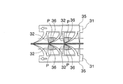


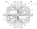
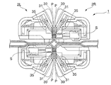
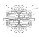
















Classifications
-
- A—HUMAN NECESSITIES
- A61—MEDICAL OR VETERINARY SCIENCE; HYGIENE
- A61B—DIAGNOSIS; SURGERY; IDENTIFICATION
- A61B17/00—Surgical instruments, devices or methods
- A61B17/11—Surgical instruments, devices or methods for performing anastomosis; Buttons for anastomosis
- A61B17/115—Staplers for performing anastomosis, e.g. in a single operation
- A61B17/1152—Staplers for performing anastomosis, e.g. in a single operation applying the staples on the outside of the lumen
-
- A—HUMAN NECESSITIES
- A61—MEDICAL OR VETERINARY SCIENCE; HYGIENE
- A61B—DIAGNOSIS; SURGERY; IDENTIFICATION
- A61B17/00—Surgical instruments, devices or methods
- A61B17/068—Surgical staplers, e.g. containing multiple staples or clamps
- A61B17/072—Surgical staplers, e.g. containing multiple staples or clamps for applying a row of staples in a single action, e.g. the staples being applied simultaneously
- A61B17/07207—Surgical staplers, e.g. containing multiple staples or clamps for applying a row of staples in a single action, e.g. the staples being applied simultaneously the staples being applied sequentially
-
- A—HUMAN NECESSITIES
- A61—MEDICAL OR VETERINARY SCIENCE; HYGIENE
- A61B—DIAGNOSIS; SURGERY; IDENTIFICATION
- A61B17/00—Surgical instruments, devices or methods
- A61B17/068—Surgical staplers, e.g. containing multiple staples or clamps
- A61B17/072—Surgical staplers, e.g. containing multiple staples or clamps for applying a row of staples in a single action, e.g. the staples being applied simultaneously
- A61B2017/07214—Stapler heads
-
- A—HUMAN NECESSITIES
- A61—MEDICAL OR VETERINARY SCIENCE; HYGIENE
- A61B—DIAGNOSIS; SURGERY; IDENTIFICATION
- A61B17/00—Surgical instruments, devices or methods
- A61B17/11—Surgical instruments, devices or methods for performing anastomosis; Buttons for anastomosis
- A61B2017/1121—Surgical instruments, devices or methods for performing anastomosis; Buttons for anastomosis adapted for performing tissue or graft eversion
Definitions
- the present invention relates to a clamp member, a clamp, and an anastomosis device for grasping an organ tissue for suturing or anastomosing a digestive tract or the like in a surgical operation.
- the inner anastomosis in which the vicinity of the stump portion of the cylindrical living tissue is bent inward and sutured in the tube, and the vicinity of the stump portion is bent outward.
- the valgus anastomosis that is sutured outside the tube is known.
- the varus anastomosis is generally performed from the viewpoint of hygiene, adhesion prevention, etc., and in the varus anastomosis of the digestive tract, staples that are suture members are arranged in a ring shape.
- the annular automatic anastomosis device is the first choice (see, for example, Patent Document 1).
- an anastomosis device is a means for efficiently performing valgus anastomosis in a short time.
- the present invention has been made in view of such circumstances, and an object thereof is to solve at least one of the problems described below.
- 1st invention which concerns on this invention is a clamp member, Comprising: It has the clamp surface which pinches
- a first holding tooth plate member in which a plurality of piercing teeth are arranged at an equal pitch in the longitudinal direction of the fork, and the first holding tooth plate member is disposed along the first holding tooth plate member and corresponds to each piercing tooth.
- the rake teeth have a plurality of rake teeth that are arranged at an equal pitch to the piercing teeth that are formed with the tip side facing the corresponding piercing tooth side, and move relative to the first grasping tooth plate member.
- a second gripping tooth plate member configured so that a tip end portion thereof matches a tip portion of the piercing tooth, and the first gripping tooth plate member and the second gripping tooth plate member can be moved relative to each other.
- a gripping tooth drive unit that is connected to at least one of the plate members and relatively moves the first gripping toothplate member and the second gripping toothplate member by one pitch in the longitudinal direction;
- An organ gripping mechanism configured to grip the vicinity of a suture portion of the tissue, and connected to the organ gripping mechanism, crossing the organ gripping mechanism across the longitudinal direction of the fork, and the piercing teeth are sutured of the organ tissue
- a valgus mechanism configured to move a valgus movement range from a position before valgus that pierces the vicinity of the part to a position after valgus where the sutured portion of the organ tissue is located on the stitching surface; and a valgus mechanism disposed on the fork.
- Defining the valgus movement range of the organ gripping mechanism holding the organ gripping mechanism at each of the pre-valgus position and the post-valgus position, and moving the organ gripping mechanism toward the valgus position
- Characterized in that it comprises a gripping management means for managing serial first gripping teeth plate member and the second gripping teeth plate member.
- the first grasping toothplate member and the second grasping toothplate member of the organ grasping mechanism move relative to each other, so that the piercing teeth pierce the vicinity of the suture part outside the organ tissue.
- the tip of the rake teeth matches the tip of the piercing tooth to grip the organ tissue, and the valgus mechanism moves the organ gripping mechanism across the longitudinal direction of the clamp member, thereby inverting the organ tissue.
- An organ wall is formed.
- that the tip portion of the rake tooth matches the tip portion of the piercing tooth means that these tip portions substantially match for the purpose of grasping the organ tissue.
- a grip management means is provided, and the first gripping tooth plate is held when the organ gripping mechanism is held at each of the pre-valgus position and the post-valgus position, and the organ gripping mechanism is moved to the post-valgus position side. Since the member and the second grasping tooth plate member are appropriately managed so as not to perform an unintended operation, the organ tissue is prevented from being detached from the piercing teeth and the rake teeth at the time of eversion, and the grasped organ The tissue can be held stably.
- 2nd invention which concerns on this invention is a clamp member which concerns on the said 1st invention, Comprising: As for the said organ holding
- the piercing teeth are configured to advance in the piercing direction, and when the piercing teeth are in the retracted position in the piercing direction, the piercing teeth and the rake teeth
- a gripping tooth protection wall portion is provided that stores the tip portion and prevents the tip portion of the piercing tooth and the rake tooth from coming into contact with the outside.
- the gripping tooth protection wall portion stores the tip portions of the piercing teeth and the rake teeth.
- the tip portion of the rake teeth is prevented from being damaged due to contact with an external object, and as a result, damage to the organ tissue due to the damaged piercing teeth and rake teeth is suppressed.
- the piercing direction means a direction in which the piercing tooth presses the outside of the organ tissue (direction in which the piercing tooth moves). Further, since the stab teeth and rake teeth are prevented from coming into contact with an operator such as a medical worker, the operator can easily, safely and efficiently handle the organ gripping mechanism.
- a third invention according to the present invention is the clamp member according to the first or second invention, wherein the piercing teeth extend in the piercing direction or in a direction inclined toward the rake teeth side. It is characterized by being formed.
- the piercing teeth are formed to extend in the piercing direction or in a direction inclined to the rake teeth side, so that the piercing can be easily performed and the organ tissue is It can be gripped well with rake teeth.
- 4th invention which concerns on this invention is a clamp member which concerns on the said 1st or 2nd invention, Comprising:
- the said piercing tooth is formed so that the front-end
- the distal end side of the piercing tooth is formed so as to be gradually displaced toward the rake tooth side, so that the organ tissue is prevented from being damaged, and the organ tissue is securely grasped. Can do.
- a fifth invention according to the present invention is the clamp member according to any one of the first to fourth inventions, wherein the organ gripping mechanism includes the organ tissue in the first gripping toothplate member.
- a first inclined notch that inclines toward the side away from the pierced tooth toward a gripping operation direction in which the second gripping toothplate member moves relative to the first gripping toothplate member.
- a first engaging cutout portion extending in the gripping operation direction from the gripping operation direction end of the first inclined cutout portion, and the second gripping toothplate member includes A second engagement notch portion that is inclined toward the side away from the rake teeth in the gripping tooth operation direction is formed, and the gripping tooth drive portion includes the first engagement notch portion and the second engagement notch.
- a gripping tooth operating member is formed to be engaged with the portion, and the gripping tooth operating member is By being moved in the working direction, the rake teeth and the tips of the piercing teeth are advanced in the piercing direction, and the rake teeth are moved toward the corresponding piercing teeth. It is characterized by.
- the gripping tooth operating member when the gripping tooth drive unit is operated, the gripping tooth operating member is engaged with the first inclined notch portion and the second engagement notch portion of the first engagement notch portion. While being moved in the gripping operation direction, the piercing teeth and the rake teeth advance in the piercing direction to pierce the organ tissue.
- the gripping tooth operating member abuts on the end of the second engagement notch in the gripping operation direction and moves along the relief of the first engagement notch, so that the second gripping tooth plate member
- the gripping tooth plate member moves in the gripping operation direction, the rake teeth move toward the corresponding piercing tooth side by one pitch, and the tip portion of the rake tooth matches the tip portion of the piercing tooth.
- one operation of the grasping tooth drive unit moves the rake teeth and piercing teeth in the piercing direction and moves the rake teeth and the piercing teeth in the direction in which they approach each other, thereby efficiently and reliably organ tissue. Can be gripped.
- a sixth invention according to the present invention is the clamp member according to any one of the first to fifth inventions, wherein the organ gripping mechanism has a guide formed on the suture surface side of the housing, By moving a cutting blade along the guide, the organ tissue arranged on the clamp surface can be separated from the suture part or a position corresponding to the suture part at an appropriate interval.
- the cutting blade since the cutting blade is guided by the guide formed on the suture surface side, the cutting blade is moved along the guide to correspond to the suture portion or the suture portion of the organ tissue.
- a cutting part (cut end) is formed at a position spaced a predetermined distance from the position.
- a seventh invention according to the present invention is the clamp member according to any one of the first to sixth inventions, wherein the valgus mechanism is disposed on each of the forks and holds each of the organs A valgus for allowing the tip of the piercing teeth and the rake teeth to pass through a predetermined valgus trajectory corresponding to the valgus movement range by being connected to a mechanism and performing a rotation, slide, or combined operation.
- An operation unit is provided.
- the valgus mechanism and the rake teeth are raked by rotating, sliding, or performing a combined operation on the valgus operation unit connected to the organ gripping mechanism.
- the tip of the tooth passes through a predetermined valgus locus corresponding to the valgus movement range. Therefore, a valgus operation unit suitable for the shape of the organ gripping mechanism and the valgus mechanism can be configured.
- An eighth invention according to the present invention is the clamp member according to any one of the first to seventh inventions, wherein the valgus mechanism is configured to remotely operate the organ gripping mechanism by the valgus operation unit.
- the organ grasping mechanism is configured to be capable of valgus and capable of holding the organ gripping mechanism at the position before valgus and the position after valgus.
- the valgus operation part can be remotely operated by the valgus operation part, and the organ gripping mechanism can be held at the valgus position and the valgus position. Can be easily operated, and the organ gripping mechanism can be securely held at the position before and after the valgus to perform a stable valgus operation.
- a ninth invention according to the present invention is the clamp member according to any one of the first to eighth inventions, wherein the valgus mechanism includes a link mechanism including at least four links, and the stitching direction.
- the tip of the piercing teeth and the rake teeth moves along a predetermined valgus locus corresponding to the valgus movement range by changing the posture of the link mechanism on a plane orthogonal to Features.
- the link mechanism including at least four links changes the posture in the plane orthogonal to the stitching direction, the tip portions of the piercing teeth and the rake teeth move along a predetermined valgus locus.
- the organ tissue can be smoothly evacuated while suppressing the tensile force on the grasped organ tissue and the elongation of the organ tissue. As a result, it is possible to suppress an excessive force from being applied to the organ tissue that is gripped during the valgus, thereby reducing the burden on the organ tissue.
- a tenth invention according to the present invention is the clamp member according to the ninth invention, wherein the organ gripping mechanism includes the gripping drive unit, the first gripping tooth plate member, and the second gripping tooth.
- the plate member is connected so as to be relatively movable in a direction crossing the longitudinal direction of the fork.
- the gripping drive unit, the first gripping toothplate member, and the second gripping toothplate member are connected so as to be relatively movable in a direction crossing the longitudinal direction of the fork. Therefore, when a valgus operation is performed, the position of the gripping tooth drive unit in the direction across the fork can be maintained as it is, and the tip of the piercing teeth and the rake teeth can be valgused.
- the operation unit can be easily operated.
- An eleventh invention according to the present invention is the clamp member according to any one of the first to eighth inventions, wherein the valgus mechanism is formed around a valgus axis formed along the stitching direction.
- a valgus rotation support portion that supports the organ gripping mechanism so that the tip portions of the piercing teeth and the rake teeth move along a predetermined valgus locus corresponding to the valgus movement range by rotating. It is characterized by providing.
- the tip of the piercing teeth and the rake teeth moves along a predetermined valgus locus by the valgus mechanism rotating around the valgus axis formed along the stitching direction. Therefore, the valgus mechanism can have a simple structure.
- a twelfth aspect of the present invention is the clamp member according to the eleventh aspect of the present invention, wherein the valgus mechanism is selectively operated at any one of the position before the valgus and the position after the valgus.
- a valgus position locking member for locking the organ gripping mechanism is provided, and the valgus position locking member holds the organ until the gripping tooth drive unit moves the piercing teeth and the rake teeth to a gripping position.
- the gripping mechanism is locked at the position before the valgus, and when the piercing teeth and the rake teeth are in a gripping state, the organ gripping mechanism is allowed to valgus and after the valgus operation is performed.
- the organ gripping mechanism is locked at the valgus position.
- the valgus position locking member locks the organ gripping mechanism at the pre-valgus position until the gripping tooth drive unit moves the piercing teeth and the rake teeth to the gripping position.
- the organ gripping mechanism can be operated valgus.
- the organ gripping mechanism is locked at the post-valgus position, so that the organ gripping mechanism is held at the post-valgus position.
- the organ gripping mechanism and the valgus mechanism can be stably held until the anastomosis is completed.
- a thirteenth aspect of the present invention is the clamp member according to the twelfth aspect of the present invention, wherein the valgus position locking member is moved together with the organ gripping mechanism, and the pierced teeth and the rake teeth Is moved relative to the organ gripping mechanism when moved to the gripping position, and the organ gripping mechanism is locked at the valgus front position until the piercing teeth and the rake teeth move to the gripping position.
- the gripping mechanism When the gripping mechanism is evacuated, it moves relative to the organ gripping mechanism, and the locking with the organ gripping mechanism switches from the valgus front position locking part to the valgus rear position locking part. It is comprised as follows.
- the clamp member according to the present invention has the valgus position locking member that is moved together with the organ gripping mechanism, the valgus position locking portion formed on the valgus position locking member, The posterior position locking portion is configured to hold the organ gripping mechanism at the valgus position and the valgus position.
- the valgus position locking member moves relative to the organ gripping mechanism, so that the locking with the organ gripping mechanism is performed from the valgus front position locking portion to the post valgus position. Switch to the locking part.
- the organ gripping mechanism can be reliably held at the position before and after the valgus with a simple configuration.
- 14th invention which concerns on this invention is a clamp, Comprising: The clamp member which concerns on any one said 1st thru
- the clamp is configured by arranging two clamp members as a pair so that the clamp surfaces are opposed to each other. Therefore, organ tissues sandwiched between the clamps are held by the organs of the respective clamp members.
- the gripping and valving can be easily and efficiently performed.
- a fifteenth aspect of the present invention is the clamp according to the fourteenth aspect of the present invention, further comprising grasping operation synchronization means for synchronously moving the organ grasping mechanism disposed on each of the clamp members.
- the gripping operation synchronizing means that operates the corresponding organ gripping mechanisms in synchronization with each other is provided, the piercing teeth and the rake teeth are disposed on both sides of the organ between the hollow portions.
- the tissue can be grasped at the same time.
- the organ tissue can be grasped stably, and stable suturing and anastomosis can be performed.
- the clamp according to the fourteenth or fifteenth aspect of the present invention is configured so that the stitching surfaces are separated from each other and accessible, and when approaching each other, the stitching surfaces face each other.
- a clamp in which two clamp members are disposed as a pair and the two are disposed as a pair, each of two pairs of clamp members configured as a pair of two clamp members facing each other on the stitching surface, A staple accommodating portion which is disposed on one of the clamp members and has a slot through which staples pass on the stitching surface side and accommodates the staple; an ejection portion which pushes out the staple from the staple accommodating portion; and the clamp An anvil member disposed on the other clamp member of the pair of members and having a shape portion for forming the staple on the stitching surface side.
- the engagement mechanism is formed.
- the suture mechanism is formed in each of the two pairs of clamp members, and the stitched portions of the organ wall formed by the valgus are brought into contact with each other and sutured with staples. Can be performed efficiently and stably.
- the organ tissue is restrained from being detached from the piercing teeth and the rake teeth at the time of valgus, so that the grasped organ tissue can be stably held.
- the sandwiched organ tissue can be easily and efficiently grasped and evacuated by the organ grasping mechanism and the valgus mechanism of each clamp member constituting the clamp.
- anastomosis instrument according to the present invention anastomosis of organ tissues can be performed efficiently and stably.
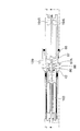
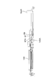
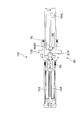
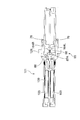
- interval maintenance means which concerns on the anastomosis instrument of 1st Embodiment
- interval maintenance means which concerns on the anastomosis instrument of 1st Embodiment
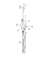
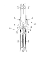
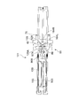
- latching of the organ grasping mechanism by the valgus knob concerning the anastomosis instrument of a 1st embodiment and is a figure showing the state in the middle of valgus.
- FIG. 1 It is a perspective view which shows 2nd Embodiment of the organ holding
- 44A is a view for explaining a valgus mechanism of the anastomotic apparatus according to the second embodiment of the present invention, and is a view showing a cross section AA of FIG. 43B. It is a figure explaining the valgus mechanism of the anastomotic device concerning the 2nd Embodiment of this invention, and is a top view which shows the state after the valgus seen from the clamp surface side. It is a figure explaining the valgus mechanism of the anastomotic apparatus concerning the 2nd Embodiment of this invention, and is a top view which shows the state after the valgus seen from the opposite side of the clamp surface.
- 45A is a view for explaining the valgus mechanism of the anastomotic apparatus according to the second embodiment of the present invention, and is a view showing a BB cross section of FIG. 44B. It is a perspective view which shows the state before the valgus explaining the valgus mechanism of the anastomosis apparatus which concerns on the 2nd Embodiment of this invention. It is a perspective view which shows the state after the valgus explaining the valgus mechanism of the anastomosis instrument concerning the 2nd Embodiment of this invention.
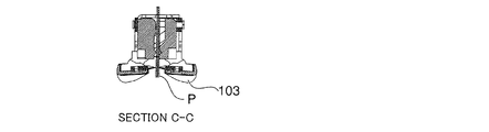
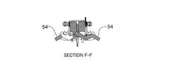
- FIG. 52A is a view for explaining the valgus mechanism of the anastomotic apparatus according to the second embodiment of the present invention, and is a view showing a DD section of FIG. 51A.
- FIG. 52A is a view for explaining the valgus mechanism of the anastomotic apparatus according to the second embodiment of the present invention, and is a view showing a CC cross section of FIG. 51A.
- FIG. 52A is a view for explaining a valgus mechanism of the anastomotic apparatus according to the second embodiment of the present invention, and is a view showing a FF cross section of FIG. 51A.
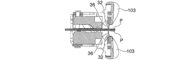
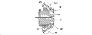
- FIG. 52B is a view for explaining the valgus mechanism of the anastomotic apparatus according to the second embodiment of the present invention, and showing the EE cross section of FIG. 51A.
- FIG. 52B is a view for explaining the valgus mechanism of the anastomotic apparatus according to the second embodiment of the present invention, and is a view showing a HH cross section of FIG. 51A.
- FIG. 52B is a view for explaining the valgus mechanism of the anastomotic apparatus according to the second embodiment of the present invention, and showing the GG cross section of FIG. 51A.
- FIG. 1 It is a figure explaining the valgus mechanism of the anastomotic device concerning the 2nd Embodiment of this invention, and is sectional drawing which shows the state before an organ tissue is valgused. It is a figure explaining the valgus mechanism of the anastomosis apparatus concerning the 2nd Embodiment of this invention, and is sectional drawing which shows the state in the middle of the organ tissue valgus. It is a figure explaining the valgus mechanism of the anastomosis instrument concerning the 2nd Embodiment of this invention, and is sectional drawing which shows the state after an organ tissue is valgus. It is a top view explaining the lock release means of the anastomosis apparatus concerning the 2nd Embodiment of this invention.
- FIG. 1 It is a figure explaining the valgus mechanism of the anastomotic device concerning the 2nd Embodiment of this invention, and is sectional drawing which shows the state before an organ tissue is valgused. It is a
- 55B is a view for explaining unlocking means of the anastomotic apparatus according to the second embodiment of the present invention, and is a view showing a JJ cross section of FIG. 55A. It is an enlarged view explaining the principal part of the lock release means of the anastomosis instrument concerning the 2nd Embodiment of this invention. It is a top view explaining the lock release means of the anastomosis apparatus concerning the 2nd Embodiment of this invention. It is a side view explaining the lock release means of the anastomosis instrument concerning the 2nd Embodiment of the present invention. It is a top view explaining the lock release means of the anastomosis apparatus concerning the 2nd Embodiment of this invention.
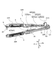
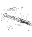
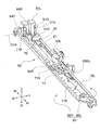
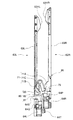
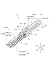
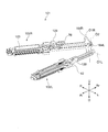
- FIG. 1 to FIG. 3 are diagrams showing an anastomosis apparatus according to the present invention, in which reference numeral 1 indicates an anastomosis apparatus, and reference numerals 2R and 2L indicate clamps.
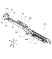
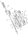
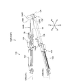
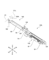
- 4 and 5 show a pair of clamp members 20R (comprising a clamp member 21R and a clamp member 25R) constituting the clamp 2R, and a pair of clamp members 20L (a clamp member 21L and a clamp) constituting the clamp 2L.
- 6 is a diagram showing the clamp member 25L.
- Reference numerals R, L, Fr, Rr, U, and D attached to the coordinate axes shown in FIG. 1 to FIG. 6 indicate directions related to the anastomosis instrument 1 and its constituent members. The right (R), left (L), Fr (front end side), upper side (U), and lower side (D) are shown when the front side is called the front side.
- the anastomosis instrument 1 includes a clamp 2 ⁇ / b> R that can rotate around the axis O ⁇ b> 1 ⁇ / b> R and a clamp 2 ⁇ / b> L that can rotate around the axis O ⁇ b> 1 ⁇ / b> L.
- the clamp 2R and the clamp 2L are rotatable around the axes O1R and O1L, respectively.
- the clamp 2R and the clamp 2L are formed coaxially with the axis O2 orthogonal to the axis O1L formed in the clamp 2L in the connecting hole 23R formed coaxially with the axis O2 orthogonal to the axis O1R formed in the clamp 2R.
- the coupling pin 23L is inserted to be coupled, and the clamp 2R and the clamp 2L are rotatable around the axis O2.
- the axis O1R of the clamp 2R and the axis O1L of the clamp 2L are arranged on one axis O1.
- the axis O1 and the axis O2 do not mean absolute coordinates in space, but are axes based on the anastomosis instrument 1 when the clamps 2R and 2L are closed to constitute the anastomosis instrument 1.
- the clamp 2 ⁇ / b> R includes a clamp member 21 ⁇ / b> R and a clamp member 25 ⁇ / b> R, and each clamp member 21 ⁇ / b> R, 25 ⁇ / b> R is formed by extending in the stitching direction when used as the anastomosis instrument 1.
- the organ gripping mechanism 3 disposed in the longitudinal direction of the clamp members 21R and 25R, and the organ gripped by the organ gripping mechanism 3 by changing the posture of the organ gripping mechanism 3 in a cross section orthogonal to the longitudinal direction of the clamp members 21R and 25R.
- a valgus mechanism 5 for inverting the end of the tissue, a firing mechanism 60 and an anvil member 67, and a grip management means are provided.
- the clamp surface of the clamp member 21R and the clamp surface of the clamp member 25R are configured to be able to face each other, and the organ tissue can be sandwiched by closing the clamp member 21R and the clamp member 25R. Yes.
- the clamp 2L includes a clamp member 21L and a clamp member 25L, and each clamp member 21L, 25L is formed to extend in the stitching direction when used as the anastomosis instrument 1.
- the fork, the organ gripping mechanism 3 disposed in the longitudinal direction of the clamp members 21L and 25L, and the organ gripping mechanism 3 in a cross-section orthogonal to the longitudinal direction of the clamp members 21L and 25L.
- the valgus mechanism 5 that causes the end of the organ tissue to valgus, the firing mechanism 60 and the anvil member 67, and grip management means are provided.
- the clamp surface of the clamp member 21L and the clamp surface of the clamp member 25L are configured to be able to face each other, and the organ tissue can be sandwiched by closing the clamp member 21L and the clamp member 25L. Yes.
- the clamp 2R and the clamp 2L can be closed around the axis O2 when all the valgus mechanisms 5 provided on the clamp members 21R, 25R, 21L, and 25L are operated valgus. Yes.
- the clamp 2R and the clamp 2L constitute two pairs of clamp members 21 and 25 that face each other when the anastomosis instrument 1 is closed around the axis O2.
- the mutually facing surfaces between the clamp member 21R and the clamp member 21L constituting the clamp member pair 21 and between the clamp member 21R and the clamp member 21L constituting the clamp member pair 25 are stitched facing surfaces (stitched surfaces). Yes.
- a suturing mechanism including a firing mechanism 60 and an anvil member 67 is configured between the clamp members 21R and 21L and the clamp members 21L and 21R facing each other.
- the firing mechanism 60 is disposed on the clamp member 21R and the clamp member 25L
- the anvil member 67 is disposed on the clamp members 21L and 25R.
- FIG. 6 is a diagram illustrating a schematic configuration of a firing mechanism 60 disposed on the clamp member 25L of the clamp 2L.
- the firing mechanism 60 includes a staple storage unit 61 that stores the staple S and an injection unit 62. ing.
- each of the clamp members 21R and 25R of the clamp 2R and the clamp members 21L and 25L of the clamp 2L are covered with, for example, a lightweight plastic resin appearance cover that suppresses reaction with organ tissue.
- the organ gripping mechanism 3 includes a stab tooth member (first grip tooth plate member) 31, a rake tooth member (second grip tooth plate member) 35, a housing 39, and a grip tooth operation.
- a member (gripping tooth operating member) 40 and an engagement pin (first engagement member, second engagement member) 43 are provided, and from the front side (sewn surface side), the housing 39, the piercing tooth member 31, and the rake teeth
- the member 35 and the grasping tooth actuating member 40 are arranged in this order so as to grasp the vicinity of the sutured portion of the organ tissue.
- the housing 39 can store the piercing tooth member 31 and the rake tooth member 35 including the distal end portion 32A of the piercing tooth 32 and the distal end portion 36A of the rake tooth 36.
- the exposure on the tip side is suppressed.
- the piercing direction means the direction in which the piercing tooth presses the outside of the organ tissue (the direction in which the piercing tooth moves).
- the piercing tooth member 31 and the rake teeth 36 are arranged in a state where the rake teeth 36 are retracted to the front side by one pitch (interval of the piercing teeth 32) with respect to the piercing teeth 32, and the rake teeth 36 advance one pitch.
- the tip portion 36A of the rake tooth 36 substantially coincides (matches) with the tip portion 32A of the piercing tooth 32 one pitch ahead.
- the piercing tooth member 31 is made of a plate-like member.
- a plurality of piercing teeth 32 formed in a straight needle shape are arranged in a comb-teeth shape at an equal pitch, and the piercing tooth 32 has a first engagement notch 33.
- the first engagement notch 33 is inclined first toward the side away from the piercing teeth 32 from the front side (one side) in the arrangement direction of the piercing teeth 32 toward the distal end side (the other side).
- An inclined notch 33A and a relief portion 33B extending from the first inclined notch 33A to the front end side in the arrangement direction are formed.
- the rake tooth member 35 is formed of a plate-like member arranged in parallel with the piercing tooth member 31.
- a plurality of rake teeth 36 formed in a hook needle shape correspond to the piercing teeth 32, and the corresponding piercing piercing teeth 35 are formed.
- a second engagement notch portion 37 is formed which is arranged at an equal pitch to the teeth 32 and is inclined toward the side away from the rake teeth 36 from one side to the other side.
- the rake teeth 36 are formed so that the distal end side thereof faces the distal end sides of the clamp members 20R and 20L, and the rake teeth 36 are advanced by one pitch relative to the piercing teeth 32 so that the piercing teeth 32 are pierced by the organ.
- the rake teeth 36 are hooked on the tissue P to grasp the organ tissue P.
- the housing 39 is disposed on the front surface side of the piercing tooth member 31 and the rake tooth member 35, suppresses the exposure of the tip side of the piercing tooth 32 and the rake tooth 36, damages the piercing tooth 32 and the rake tooth 36, and the operator. It is designed to suppress the contact. Further, two long holes 39A are formed in the housing 39 in the arrangement direction of the piercing teeth 32, and the engagement pins 43 are movable along the long holes 39A.
- the gripping tooth operating member 40 is provided with two engaging pins 43.
- the engaging pins 43 are connected to the piercing tooth member 31, the rake tooth member 35, and the housing 39.
- the clamp members 20R and 20L are relatively moved from the front side to the tip side.
- the first inclined cutout portion 33A, the second engagement cutout portion 37, and the engagement pin 43 constitute a first driving mechanism, and the engagement pin 43 moves from the front side to the distal end side to thereby pierce the tooth. 32 and rake teeth 36 are moved in the direction of arrow ⁇ to be exposed from the edge 39E of the housing 39.
- the relief portion 33B, the second engagement notch portion 37, and the engagement pin 43 constitute a second drive mechanism, and the engagement pin 43 moves from the front side to the distal end side to the relief portion 33B.
- the rake tooth member 35 and the piercing tooth member 31 are introduced by engaging with the second engagement notch portion 37 and moving the distal end side wall portion of the second engagement notch portion 37 from the near side to the tip side.
- the phase of the rake teeth 36 and the piercing teeth 32 is changed by one pitch by moving the rake teeth 36 in the arrow ⁇ direction by relatively moving the piercing teeth 32 in the arrangement direction.
- the first drive mechanism and the second drive mechanism are both connected to the operation knob 41, and the operation knob 41 is operated so that the rake teeth 36 are moved in the longitudinal direction relative to the piercing teeth 32. 1 pitch, and exposed from the edge 39E of the housing 39.
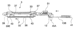
- FIGS. 8A and 8B are diagrams schematically showing the organ gripping mechanism 3.
- the gripping tooth operating member 40 is connected to the connecting rod 12 via a connecting member 44, and the connecting rod 12 is connected via a UB connector 13.
- the connecting member 13B is connected to the operation knob 41.
- the gripping tooth operating member 40 is engaged with the engagement recess 12G of the connecting rod 12 via the engagement protrusion 40A.
- the engagement recess 12G is formed so that the width of the end face 12H in the longitudinal direction is slightly wider than the engagement protrusion 40A.
- the connecting rod 12 is inserted into a valgus operation knob 51 described later so as to be slidable in the axial direction, and the operation knob 41 is moved from the front side to the tip side (right to left side in FIG. 8A) as shown in FIG. 8B. By doing so, the stab teeth 32 and the rake teeth 36 are moved in the organ gripping mechanism 3 in a direction to be exposed from the edge 39E of the housing 39. Further, the connecting rod 12 has a portion inserted into the valgus operation knob 51 formed, for example, as a square pole. When the valgus operation knob 51 is rotated, the linking rod 12 is rotated and the valgus mechanism is rotated. 5 is configured so that the piercing teeth 32 and the rake teeth 36 of the organ gripping mechanism 3 are in a valgus state. Further, the rotation of the valgus operation knob 51 is not transmitted to the UB connector 13.
- FIGS. 9A, 9B, and 9C the operation of the organ gripping mechanism 3 will be described with reference to FIGS. 9A, 9B, and 9C.
- the operation knob 41 is operated (moved from the right to the left in FIG. 9A) to move the connecting member 13B as shown in FIG. 9A, the connecting rod 12 moves forward and the engaging pin 43 moves to the piercing tooth member 31.
- the first inclined notch 33A and the inclined portion of the second engagement notch 37 of the rake tooth member 35 are engaged.
- the engaging pin 43 is inclined by the first inclined notch 33A of the piercing tooth member 31 and the inclined portion of the second engaging notch 37 of the rake tooth member 35.
- the piercing teeth 32 and the rake teeth 36 are moved in the direction of the arrow ⁇ and exposed from the edge 39E of the housing 39.
- the engagement pin 43 is guided to the relief portion 33 ⁇ / b> B of the piercing tooth member 31 and is engaged with the second engagement notch portion 37 of the rake tooth member 35, so that the second engagement notch portion 37 is engaged.
- the first gripping toothplate member and the second gripping toothplate member are such that the gripping tooth drive unit is connected to at least one of the first gripping toothplate member and the second gripping toothplate member.
- the configuration may be such that they can move relative to each other.
- the housing 39 has a cutting blade for cutting the organ tissue so that an appropriate interval is secured from the sutured portion in the anastomosis of the organ tissue P on the front surface (the end of the organ tissue P is present).
- a cut protector for cutting off the organ tissue that is cut off by C and used as a stump portion at a predetermined distance K from the position corresponding to the suture portion (here, the distal end portion 32A of the piercing tooth 32).
- Guide 39B is formed.
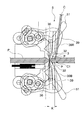
- the cutting portion C1 at the distal end of the cutting blade C causes the organ tissue P sandwiched between the clamp surfaces to the distal end portion 32A of the piercing tooth 32.
- the cut protector 39B preferably crosses the gripping tooth distal end side in the range of 10 ° to 45 ° with respect to the direction in which the piercing teeth 32 extend.
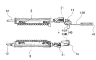
- each clamp 2R, 2L has, for example, a synchronization convex portion 45A formed on the UB connector 13 of one of the clamp members, and the other clamp member corresponding to the UB connector 13.
- the disposed connector 14 is formed with a synchronization recess 45B.
- the synchronization convex portion 45A and the synchronization concave portion 45B constitute a gripping operation synchronization means 45 that moves the organ gripping mechanism 3 in synchronization.
- the two organ gripping mechanisms 3 that are opposed to each other by closing the clamps 2R and 2L and inserting the synchronization convex portion 45A into the synchronization concave portion 45B sandwich the organ tissue P between the clamp surfaces.
- the piercing teeth 32 and the rake teeth 36 are driven synchronously.
- the valgus mechanism 5 is configured such that a valgus operation knob (valgus operation portion) 51 for valgus operating the organ gripping mechanism 3 by remote operation and a connecting rod 12 rotate across the longitudinal direction of the fork.
- the link 53 that changes its posture when viewed from the axial direction along the longitudinal direction of the organ 1 causes the organ gripping mechanism 3 to move from the position before the valgus where it pierces the vicinity of the suture portion to the outside where the suture portion of the organ tissue is located on the suture surface. It is configured to move in the valgus movement range that reaches the reverse position.
- an engagement for locking the valgus mechanism 5 at the valgus position and the valgus position is provided.
- a joint is provided.
- the valgus operation knob 51 is formed with a lock recess into which a lock protrusion (not shown) formed in the valgus operation knob 51 enters when the valgus operation is performed, and the valgus operation knob 51 is rotated.
- the locking convex portion engages with the locking concave portion and the piercing teeth 32 and the rake teeth 36 of the organ gripping mechanism 3 are held at the exposed positions, and the organ gripping mechanism 3 is held at the valgus post-rotation position.
- the valgus state is maintained.
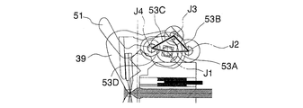
- the link 53 is composed of four (four or more) links 53A, 53B, 53C, and 53D as shown in FIGS. 12A and 12B.
- the link 53A has an anastomosis at one end. 1 is formed between the fulcrums J1 and J2 which are formed on the main body side and formed as a fulcrum J1 which coincides with the rotation axis of the connecting rod 12 and whose other end is a fulcrum J2 formed on the link member 52B.
- the link 53B is formed between fulcrums J2 and J3 having one end as a fulcrum J2 formed on the link member 52B and the other end as a fulcrum J3 formed on the housing 39, and the link 53C is formed on the housing 39 at one end.
- the link 53D is formed between the fulcrum J4 and the fulcrum J1 formed on the housing 39, respectively.
- the link 53D is formed between the fulcrum J4 and the fulcrum J1 formed on the housing 39.
- the valgus mechanism 5 is a rectangular link 53 formed by links 53A, 53B, 53C, 53D.
- FIG. 13 is a diagram showing the valgus locus of the organ tissue P by the valgus mechanism 5 including the link 53.
- the organ gripping mechanism 3 grips the valgus operation knob 51 by rotating the valgus operation knob 51.
- the organ tissue P can be smoothly evacuated with a small force, and a simple structure can reduce the burden on the organ tissue P by suppressing an excessive stretching force from being applied to the organ tissue P during valgus. it can.
- the clamps 2R and 2L constituting the anastomosis apparatus 1 maintain the clamp member interval for adjusting and holding the interval between the pair of clamp members 20R and 20L to a predetermined interval by rotating the valgus operation knob 51 at the time of valgus.
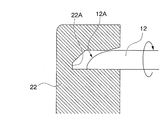
- the clamp member interval maintaining means includes, for example, a fork connecting member 22 provided on the distal end side of one of the clamp members 20 constituting the clamp 2 and the other clamp member 20.
- the fork connecting member 22 is provided with a storage space for storing the distal end portion 12A of the connecting rod 12.
- the distal end portion 12A of the connecting rod 12 has a taper formed on one side surface on the distal end side and a flat surface portion formed on the other side surface, and the storage space of the fork connecting member 22 is in a state in which it is not reversed.
- the distal end portion 12A of the connecting rod 12 can be easily inserted into the accommodating space, and an inner wall surface is formed that is pressed by the flat portion of the distal end portion 12A when the organ gripping mechanism 3 is turned outward.
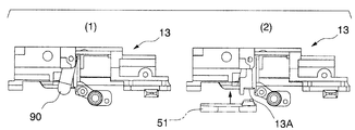
- each clamp 2 manages the piercing tooth member 31 and the rake tooth member 35 so that they do not move relative to each other when the organ gripping mechanism 3 moves to the valgus rear position side. It has a grip management means for preventing the grip mechanism 3 from coming off.
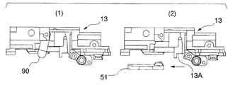
- the grip management means includes a locking recess 13A formed on the UB connector 13, and a locking protrusion 51A formed on the front side in the rotational direction of the valgus operation knob 51 in the valgus operation of the valgus operation knob 51.
- the locking projection 51A is inserted into the locking recess 13A.
- FIGS. 15A (1) and (2) when the organ grasping mechanism 3 is advanced to grasp the organ tissue P by the piercing teeth 32 and the rake teeth 36, the UB connector 13 is also advanced.
- FIGS. 15B (1) and (2) when the UB connector 13 moves forward, the locking recess 13 A reaches a position corresponding to the locking protrusion 51 A of the valgus operation knob 51.
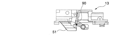
- FIGS. 15C (1) and 15 (2) when the knob 51 is turned to the valgus state, the locking convex portion 51A is inserted into the locking concave portion 13A and the retreat of the UB connector 13 is suppressed. Is done. 15A (1), FIG. 15B (1), and FIG.
- FIG. 15C (1) are views showing the orientation of the release member 90 with respect to the UB connector 13, and FIG. 15A (2), FIG. 15B (2), and FIG. (2) is a figure which shows the relative position with the latching convex part 51A of the valgus operation knob 51, and the release member 90 is abbreviate
- 15A (2) and 15B (2), the valgus operation knob 51 indicated by a two-dot chain line conceptually shows the relative positions of the locking convex portion 51A and the locking concave portion 13A.
- the mechanism for stably grasping the organ tissue P in the valgus state may be realized by another mechanism, and the setting of the mechanism can be arbitrarily selected.
- the suturing mechanism includes a clamp member 21R and a clamp member 25R that constitute the clamp 2R, and a clamp member 21L and a clamp member 25L that constitute the clamp 2L. It is comprised between two pairs of clamp members 21 and 25 that can be opposed to each other between the clamps 2R and 2L.
- the two sets of stitching mechanisms each include a firing mechanism 60 and an anvil member 67. ing.
- FIGS. 18A and 18B illustrate the operation of the suturing mechanism.
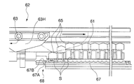
- the firing mechanism 60 includes an upper firing mechanism 60R disposed on the clamp 2R and a lower firing mechanism 60L disposed on the clamp 2L as shown in FIGS. 4 and 5, and each firing mechanism. 60 includes an ejection unit 62 and a staple storage unit 61 that holds the staple S as shown in FIG. 18A.
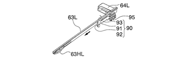
- the ejection sliders 63R and 63L are provided on the frame 11R for constituting the clamp member 21R of the clamp 2R, and the ejection slider 63R constituting the upper suturing mechanism in the anastomosis instrument 1
- the ejection slider 63L constituting the side stitching mechanism is provided on a frame for constituting the clamp member 25L of the clamp 2L.
- the firing mechanism 60 is disposed on the clamp members (one clamp member) 21R, 25L of the pair of clamp members 21, 25, and the anvil member 67 is disposed on the clamp members (the other clamp member) 21L, 25R. Has been.
- an upper firing mechanism 60R for suturing the upper side when the operator holds the anastomosis instrument 1 is disposed on the clamp member 21R, and the clamp 2L
- An anvil member 67R corresponding to the lower firing mechanism 60R to be disposed is disposed on the clamp member 21R.
- the lower firing mechanism 60L is disposed on the clamp member 25L, and the anvil member 67L is disposed on the clamp member 21L.
- the staple storage portion 61 has a plurality of holding holes (not shown) corresponding to the shape and arrangement of the staples S.
- the holding holes are along the longitudinal direction of the respective clamp members 21R and 25L.
- the upper and lower two rows of staples S are arranged in parallel.
- the injection unit 62 inputs to the injection slider 63, the slider head 63H formed at the tip of the injection slider 63, and the injection slider 63 as shown in FIGS.
- An injection knob 64 and a knockout 65 are provided.
- the ejection slider 63 includes an ejection slider 63R and an ejection slider 63L.
- the staple S is made of a material that has high strength and corrosion resistance and hardly generates a biological reaction, such as titanium, and is formed in a “U” shape, and is bent on both sides with respect to the central shaft portion. These needle portions are bent toward the center side of the central shaft portion, so that the stacked organ tissues P are locked and sutured together.
- each anvil member 67 is provided with two rows of molding recesses for bending and molding the needle portions on both sides of the ejected staple S toward the center side of the central shaft portion.
- the staple storage units 61R and 61L are disposed corresponding to the staple storage units 61R and 61L.
- the suturing mechanism advances the ejection slider 63 so that the slider head 63H presses the taper portion of the knockout 65 and advances the staple S to the staple S side stored in the staple storage portion 61. Injection is sequentially performed toward the anvil member 67.
- a slider guide 64S extending from the injection knob 64R to the front of the injection knob 64L is formed on the front side of the injection slider 64R in the moving direction of the injection knob 64R (moving direction at the time of injection).
- the slider guide 64S engages with a guide formed on a frame (not shown) of the clamp member 21L corresponding to the frame 11R to suppress lateral blur when the injection knob 64R moves forward and backward.
- the slider guide 64S constitutes an injection order management means, and the injection slider 63L advances before the injection slider 63R, and the injection when the injection slider 63R is at the origin position (position before operation). The slider 63L is prevented from moving forward.
- a slider guide 64T is formed on the rear side of the injection slider 64L in the moving direction of the injection knob 64L.
- the slider guide 64T has the clamp member 25L and the clamp member 25R closed. In this case, by engaging with a guide gap formed between a frame and a corresponding frame (not shown), lateral blurring when the injection knob 64L moves forward and backward is suppressed. .
- the injection knobs 64R and 64L are formed with lock knobs 64P and 64Q, respectively.
- the injection knobs 64R and 64L are formed by pushing the lock knobs 64P and 64Q so that the engaging portions formed on the lock knobs 64P and 64Q are guides for the frame.
- the injection knobs 64R and 64L can be moved forward when the engagement with a notch formed in the portion (for example, the notch 11P in the frame 11R) is released. As a result, erroneous operation of the forward movement of each of the injection knobs 64R and 64L is suppressed.
- the suturing mechanism is provided with a floating mechanism 68.
- the floating mechanism 68 has a diameter of an anvil mounting hole 67A for mounting the anvil member 67 in the clamp 2 larger than that of the mounting screw 67B. It is configured by being formed slightly larger, and can be adjusted within a predetermined range of the relative position of the anvil member 67 with respect to the staple storage portion 61.
- the floating mechanism 68 is provided on the anvil member 67 side and the staple storage unit 61 is fixed.
- the floating mechanism 68 is provided on either the staple storage unit 61 or the anvil member 67.
- the floating mechanism 68 may be provided on the staple storage unit 61 side, or may be provided on both the staple storage unit 61 and the anvil member 67.
- the suturing mechanism is provided with a positioning pin 61A (positioning means) as shown in FIG. 18B on the suturing facing surface of the staple storage portion 61, and a positioning hole (positioning position) on the suturing facing surface of the anvil member 67.
- 66A is formed, and the relative position between the staple storage portion 61 and the anvil member 67 is maintained by inserting the positioning pin 61A into the positioning hole 66A.
- the anastomosis instrument 1 is provided with a preceding injection portion locking means, and the injection portion that has been operated first among the two sets of suturing mechanisms is locked at the injection end position so as to be immovable.
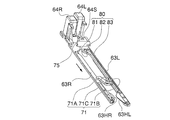
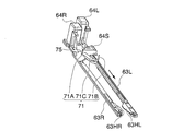
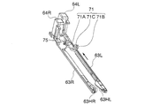
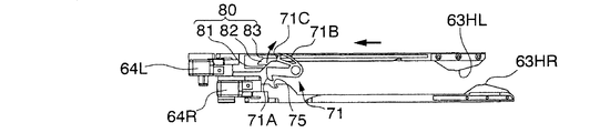
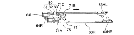
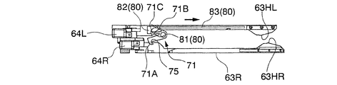
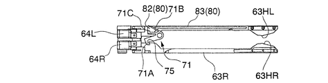
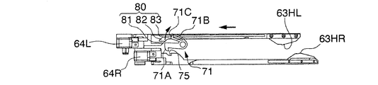
- the preceding injection portion locking means includes a slider lock recess 75 formed in the injection slider 63R as shown in FIGS. 19A to 19D and FIGS. 20A to 20E, and a slider lock provided in the anastomosis instrument body. And a member 71.
- the slider lock member 71 includes, for example, three arms extending from a member main body formed of a resin such as plastic and having an attachment hole for attachment to the anastomosis instrument 1. The three arms are respectively locked.
- the portion 71A, the urging portion 71B, and the release pin portion 71C are formed, and when the urging portion 71B is elastically deformed, the orientation around the mounting hole of the lock portion 71A and the release pin portion 71C changes. ing.
- the preceding injection portion locking means locks the injection slider 63R by engaging the lock portion 71A of the slider lock member 71 with the slider locking recess 75 of the injection slider 63R at the forward end position.
- the ejection slider 63R is prevented from moving forward and backward.
- the ejection slider 63R is advanced to suture the organ tissue P on the upper side of the anastomotic apparatus 1 clamped by the clamp member pair 21.
- the locking portion 71A engages with the slider locking recess 75, and the ejection slider 63R becomes immovable. This state is maintained until the ejection slider 63L moves backward to the forward end and then moves backward.
- the ejection slider 63 ⁇ / b> L is advanced in order to suture the organ tissue P on the lower side of the anastomotic apparatus 1 clamped by the clamp member pair 25.
- the lock portion 71A is disengaged from the slider locking recess 75, and the ejection slider 63R can slide.
- the anastomosis instrument 1 is provided with an ejection portion unlocking means, and the ejection slider 63 to be actuated later is moved to the original position side after the ejection of the staple S is finished, so that it is moved earlier and is engaged by the preceding ejection portion locking means.
- the stopped injection slider 63 is unlocked to be movable.
- the injection portion lock releasing means has a release groove portion 80 formed on the injection slider 63L and a slider lock member 71.
- the injection portion unlocking means when the injection slider 63R (one injection portion) is operated in advance among the two sets of stitching mechanisms, When the ejection slider 63L (the other ejection part) is operated and then both ejection sliders 63R and 63L are returned to the origin position, the piercing teeth 32 and the rake teeth 36 are moved backward to move the organ gripping mechanism. 3 is released. Note that it is preferable in terms of operation that the ejection slider 63L when the ejection slider 63R that has been operated in advance is unlocked by the ejection unit unlocking means is a retracted end.
- the ejection slider 63L has a release groove portion for engaging with the lock release pin portion 71C to release the lock portion 71A from the slider locking recess 75. 80 is formed.
- the release groove portion 80 includes a pin introducing portion 81 formed on the upper surface of the ejection slider 63L, an inclined portion 82, and a deformation holding portion 83. Have.
- the slider guide 64S is not shown in FIG.
- the ejection slider 63L is advanced in order to suture the organ tissue P clamped to the lower side of the anastomosis instrument 1.
- FIG. 20B when the ejection of the staple S by the ejection slider 63L is completed, the lock release pin portion 71C comes close to the pin introduction portion 81 of the release groove portion 80.
- FIG. 20B when the ejection of the staple S by the ejection slider 63L is completed, the lock release pin portion 71C comes close to the pin introduction portion 81 of the release groove portion 80.
- the anastomosis instrument 1 has a grip release mechanism (lock release means).
- FIG. 21A to FIG. 24E are diagrams illustrating the grip release mechanism.
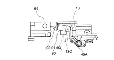
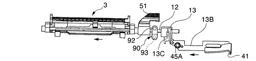
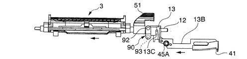
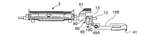
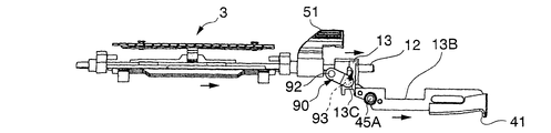
- the grip release mechanism includes a release member 90, a release member control unit 95 formed on the ejection slider 63R, and an engagement recess 13C formed on the UB connector 13 and engageable with an engagement pin 93. .
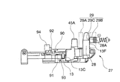
- the UB connector 13 includes an engagement recess 13C that constitutes a grip release mechanism as shown in FIGS. 21A and 21B, and an engagement pin 93 can be engaged therewith. Further, as shown in FIG. 21B, the UB connector 13 constitutes an upper and lower lock 27 for locking the upper clamp members 21R and 21L and the lower clamp members 25R and 25L in a closed state.
- the vertical lock 27 includes an engagement convex portion 28 and a release knob 29.
- the engagement convex portion 28 is disposed on the lower clamp members 25R and 25L, and the release knob 29 is disposed on the upper clamp members 21R and 21L.
- the engagement convex portion 28 is made of a plate-like member extending toward the upper clamp members 21R and 21L, and has a plurality of engagement grooves 28A formed in parallel with the axes O1R and O1L of the clamps 2R and 2L. Yes.
- the release knob 29 engages with the engagement convex portion 28 to operate the vertical lock and releases the locked vertical lock 27, and forms a hole into which the engagement convex portion 28 is inserted. It has wall part 29A and the locking member 28B which locks the engagement convex part 28.
- the locking member 28B is urged toward the engaging groove 28A, and the engaging projections 29C formed at the tip of the locking member 28B engage with the engaging groove 28A, thereby closing the clamps 2R and 2L. It is designed to lock in a locked state. Further, by moving the release knob 28 against the urging direction, the engagement of the engagement convex portion 29C with respect to the engagement groove 28A is released, and the vertical lock 27 is released.
- the release member 90 is formed with a rotation pin 92 provided on one side of one end of a release member main body 91 formed in an oval shape so as to be rotatable with respect to the anastomosis instrument 1, and the other end.
- An engaging pin 93 is formed on the surface opposite to the part where the rotating pin 92 is formed, and is connected to the anastomosis instrument 1 via the rotating pin 92.
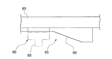
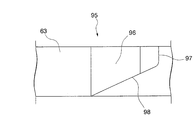
- FIG. 22A and 22B are diagrams illustrating the release member control unit 95, FIG. 22A is a side view, and FIG. 22B is a plan view showing a lower surface of the ejection slider 63R.
- the release member control unit 95 is formed on a lower surface of the ejection slider 63R, and a release member deformation inclination portion 96 in which the rear side of the injection slider 63R is gradually increased away from the lower surface of the injection slider 63R, and a release member deformation inclination portion 96.
- the release member restoration step portion 97 formed on the rear side of the release slider 63R and the engagement slider 93 of the release member 90 arranged substantially orthogonal to the injection slider 63R as the injection slider 63R moves backward are used to move the injection slider 63R in the moving direction ( And an inclined portion 98 that is rotated in the backward direction.
- FIGS. 23A to 23D and FIGS. 24A to 24E are views for explaining the operation of the grasp release mechanism.
- FIGS. 23A to 23D show the operation of the release member 90
- FIG. 23A the ejection slider 63L is advanced.
- FIG. 23B when the release member control unit 95 of the ejection slider 63L advances to the release member 90, the release member main body 91 rides on the release member deformation inclined portion 96 of the release member control unit 95. In this case, since the release member main body 91 is deformed, the release member 90 is not rotated.
- FIG. 24A to 24E are views for explaining the action of the release member 90 in the grip release mechanism.
- the operation knob 41 is advanced to operate the organ gripping mechanism 3.
- FIG. 24B shows a position in the organ gripping mechanism 3 when, for example, the piercing teeth 32 and the rake teeth 36 are both moved and exposed
- FIG. 24C shows the rake teeth 36 reaching the advancing end and organ tissue.
- the case where the UB connector 13 moves forward to the position where P is gripped (excluding the arrow in the return direction) is shown.
- the release member main body 91 is deformed until the UB connector 13 reaches the position shown in FIG. 24C through FIGS. 24A and 23B and until it reaches the state shown in FIG. 23C through FIGS. 23A and 23B. Until the release member 90 gets over the release member control unit 95, the release member 90 does not rotate.
- the release member 90 starts to rotate by the release member control unit 95 in FIGS. 23B and 23C.
- the release member 90 rotates and the engagement pin 93 of the release member 90 starts to engage with the engagement recess 13 ⁇ / b> C of the UB connector 13, and the organ is gripped via the UB connector 13.
- the connecting rod 12 of the mechanism 3 is retracted.
- the piercing teeth 32 and the rake teeth 36 are lowered into the housing 39.
- the release member 90 is rotated until it reaches the rotation end, and when the UB connector 13 is retracted to that position, the organ grasping mechanism 3 releases the organ tissue P.
- the release member 90 engages with the engagement recess 13C of the UB connector 13 to retract the UB connector 13, so that the valgus mechanism 5 can be removed from the organ tissue P without returning to the original position before valgus. Since the piercing teeth 32 and the rake teeth 36 come off, they can be removed from the anastomosis apparatus 1 while maintaining the abutting state of the anastomosed organ tissue P.
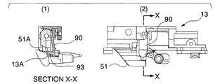
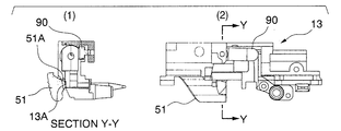
- FIGS. 25A to 25D A specific operation will be described with reference to FIGS. 25A to 25D.
- the locking convex portion 51A is inserted into the locking concave portion 13A of the UB connector 13, and FIG. 15C (1), FIG. It is a state equivalent to 15C (2).
- the engagement pin 93 is moved to the locking projection 51A as shown in FIGS. 25B (1) and (2).
- FIG. 25B (1) shows the XX cross section of FIG. 25B (2)
- FIG. 25D (1) shows the YY cross section of FIG. 25D (2).
- the operation of the anastomosis apparatus 1 will be described with reference to FIGS. 26A to 34.
- the vicinity of the end of the tubular organ tissue P is flattened between a pair of opposing clamp surfaces in the clamp 2 with a marker (not shown) as a guide, and the clamp 2 is rotated around the axis O1.
- the operation knob 41 is operated by moving and pinching.
- the piercing teeth 32 are pierced into the organ tissue P, and the organ tissue P is hooked and grasped by the rake teeth 36.
- the valgus operation knob 51 is operated to change the posture of the link 53 of the valgus mechanism 5 so that the vicinity of the end of the organ tissue P is valgus. 29 and 30 show the intermediate process.
- the valgus operation knob 51 is further rotated to move the vicinity of the end of the organ tissue P to the valgus end position.
- the two sets of clamps 2R and 2L are rotated around the axis O2, so that the clamps 2R and 2L are opposed to each other as shown in FIG.
- the end part near the part is abutted.
- the clamp 2R and the clamp 2L are sufficiently overlapped by the fork coupling hook N provided on the tip side.
- the left and right firing mechanisms 60 are operated to sew together the organ tissues P that are butted together as shown in FIG. Stitching is performed by operating the ejection knobs 64R and 64L to slide the ejection sliders 63R and 63L in order, and the slider heads 63H advance to advance the corresponding knockouts 65 to store the staples.
- the staple S is ejected from the portion 61 toward the anvil member 67 and the needle portion is bent and molded.
- the ejection slider 63L and the ejection slider 63R are retracted in order to retract the stab teeth 32 and rake teeth 36 of the organ gripping mechanism 3, and the stab teeth 32 and rake teeth 36 become organs.
- the clamps 2R and 2L are opened, and then the clamps 2R and 2L are rotated around the axis O2 to separate the clamp members 21R, 21L, 25R, and 25L of the anastomosis device from the organ tissue P.
- the piercing tooth 32 extends substantially in the piercing direction.
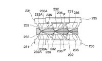
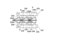
- the piercing teeth 232 may be configured to extend slightly inclined toward the rake teeth 236. By adopting such a configuration, the piercing teeth 232 can be easily pierced and the organ tissue P can be sufficiently grasped together with the rake teeth 236. it can.
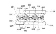
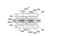
- the piercing teeth 332 may be formed in a curved shape like the rake teeth 336 so that the distal end portion 332A is gradually displaced toward the rake teeth 336 side.
- the piercing teeth 332 may be formed in a curved shape like the rake teeth 336 so that the distal end portion 332A is gradually displaced toward the rake teeth 336 side.
- the organ gripping mechanism 3 can be held at the pre-valgus position and the valgus position by the remote operation by the valgus operation knob 51.
- the operation can be easily performed, and the organ gripping mechanism 3 can be securely held at the position before valgus and the position after valgus to perform stable valgus operation.
- the organ tissue P clamped by the clamp 2 can be maintained at substantially the same thickness, so that the organ tissue P can be stably grasped and sutured.
- the organ gripping mechanism 3 is held at each of the pre-valgus position and the post-valgus position, and when the organ gripping mechanism 3 moves to the post-valgus position side, The organ tissue P is prevented from being detached from the piercing teeth 32 and the rake teeth 36, and the grasped organ tissue P can be stably held.
- the piercing teeth 32 and the rake teeth 36 are accommodated in the housing 39, so that the tip portions 32A and 36A of the piercing teeth 32 and the rake teeth 36 are in contact with an external object. And the damage is suppressed. As a result, an operator such as a medical worker can easily, safely and efficiently handle it. In addition, damage to the organ tissue P by the damaged piercing teeth 32 and rake teeth 36 is suppressed.
- the sandwiched organ tissue P can be easily and efficiently grasped and evacuated by the organ grasping mechanism 3 and the valgus mechanism 5 of the respective clamp members. Further, according to the clamps 2R and 2L, the upper and lower corresponding organ gripping mechanisms 3 are operated in synchronization, so that the organ tissue P can be gripped simultaneously from above and below, and the organ tissue P can be gripped stably. it can.
- the separation management means is provided, and the clamps 2R and 2L can be opened only when the two ejection parts are at the origin position. Can be suppressed.
- the organ tissue P is securely grasped by the organ grasping mechanism 3 and clamped on the clamp surface until the two injection knobs 64 ⁇ / b> R and 64 ⁇ / b> L are both actuated to complete the anastomosis, and thus stable.
- An anastomosis can be performed.
- anastomosis instrument 1 by operating the release knob 29, gripping by the up-and-down lock 27 and the organ gripping mechanism 3 can be easily released, and complicated procedures at the time of anastomosis and organs caused by erroneous operation The damage of the tissue P can be suppressed and a series of operation procedures can be easily and safely performed. As described above, according to the anastomosis instrument 1, the anastomosis of the organ tissue P can be performed efficiently and stably.
- FIG. 37 and FIG. 38 are views showing an anastomosis apparatus according to the present invention, in which reference numeral 101 indicates an anastomosis apparatus and reference numerals 102R and 102L indicate clamps.
- a pair of clamp members 120R (comprising a clamp member 121R and a clamp member 125R) constituting the clamp 102R, and a pair of clamp members 120L (a clamp member 121L and a clamp) constituting the clamp 102L.
- 41 is a diagram showing the clamp member 125L. Symbols R, L, Fr, Rr, U, and D attached to the coordinate axes shown in FIG. 37 to FIG. 41 indicate directions related to the anastomosis instrument 1 and its constituent members. The right (R), left (L), Fr (front end side), upper side (U), and lower side (D) are shown when the front side is called the front side.
- the anastomosis instrument 101 includes a clamp 102R that can rotate around the axis O1R and a clamp 102L that can rotate around the axis O1L.
- the clamp 102R and the clamp 102L are rotatable around the axes O1R and O1L, respectively.
- the clamp 102R and the clamp 102L are formed coaxially with the axis O2 orthogonal to the axis O1L formed in the clamp 102L in the connecting hole 123R formed coaxially with the axis O2 orthogonal to the axis O1R formed in the clamp 102R.
- the coupling pin 123L is inserted to be coupled, and the clamp 102R and the clamp 102L are rotatable around the axis O2.
- the axis O1R of the clamp 102R and the axis O1L of the clamp 102L are arranged on one axis O1. .
- a lock member (not shown) (not shown in FIG. 1) for closing the distal end side is provided with the clamp 102R and the clamp 102L closed, and the left and right clamps 102R and 102L open when performing anastomosis. It is designed to prevent this.
- the axis O1 and the axis O2 do not mean absolute coordinates in space, but are axes based on the anastomosis instrument 1 when the clamps 2R and 2L are closed to constitute the anastomosis instrument 1.
- the clamp 102R includes a clamp member 121R and a clamp member 125R.
- Each of the clamp members 121R and 125R includes a fork formed to extend in the stitching direction when used as the anastomosis instrument 101, an organ gripping mechanism 103 disposed in the longitudinal direction of the clamp members 121R and 125R, and a valgus mechanism.
- 105 a firing mechanism 160 and an anvil member 67, and grip management means.
- the valgus mechanism 105 rotates the respective organ gripping mechanisms 103 around the valgus axes O3U and O3D formed in the longitudinal direction of the respective clamp members 121R and 125R, and the organ tissue gripped by the organ gripping mechanism 103. The end of the is turned outside.
- the clamp surface of the clamp member 121R and the clamp surface of the clamp member 125R are configured to be able to face each other, and the organ tissue can be sandwiched by closing the clamp member 121R and the clamp member 125R. Yes.
- the clamp 102L includes a clamp member 121L and a clamp member 125L as shown in FIG.
- Each of the clamp members 121L and 125L includes a fork formed so as to extend in the stitching direction when used as the anastomosis instrument 101, an organ gripping mechanism 103 disposed in the longitudinal direction of the clamp members 121L and 125L, and a valgus mechanism.
- 105 a firing mechanism 160 and an anvil member 67, and grip management means.
- the valgus mechanism 105 rotates the respective organ gripping mechanisms 103 around the valgus axes O3 (O3U, O3D) formed in the longitudinal direction of the respective clamp members 121L, 125L so that the organ gripping mechanism 103 grips them.
- the end of the organ tissue is made varus.
- the valgus axis O3U and the valgus axis O3D of the clamps 120R and 102L are arranged coaxially on one valgus axis O3 when the clamps 120R and 102L are closed.
- clamp surface of the clamp member 121L and the clamp surface of the clamp member 125L are configured to be able to face each other, and the organ tissue can be sandwiched by closing the clamp member 121L and the clamp member 125L. Yes.
- the clamp 102R and the clamp 102L can be closed around the axis O2 when all the valgus mechanisms 105 provided on the clamp members 121R, 125R, 121L, and 125L are operated valgus. Yes.
- clamp 102R and the clamp 102L constitute two pairs of clamp members 121 and 125 that face each other when the anastomosis device 101 is closed around the axis O2.
- the mutually opposing surfaces between the clamp member 121R and the clamp member 121L constituting the clamp member pair 121 and between the clamp member 121R and the clamp member 121L constituting the clamp member pair 125 are stitched facing surfaces (stitched surfaces). Yes.
- a suturing mechanism including a firing mechanism 160 and an anvil member 67 is configured between the clamp members 121R and 121L and the clamp members 121L and 121R facing each other.
- the firing mechanism 160 is disposed on the clamp member 121R and the clamp member 25L
- the anvil member 67 is disposed on the clamp members 121L and 25R.
- FIG. 41 is a diagram illustrating a schematic configuration of a firing mechanism 160 disposed on the clamp member 125L of the clamp 102L.
- the firing mechanism 160 includes a staple storage unit 61 that stores the staple S, and an ejection unit.
- the injection unit has an injection knob 164L and an injection slider 63.
- the clamp 102R and the clamp 102L are covered with, for example, a lightweight plastic resin appearance cover that suppresses a reaction with an organ tissue.
- the organ gripping mechanism 103 includes a stab tooth member (first grip tooth plate member) 31, a rake tooth member (second grip tooth plate member) 35, a housing 139, and a grip tooth operation.
- a member (gripping tooth operating member) 140 and an engagement pin (first engagement member, second engagement member) 43 are provided, and from the front side (sewn surface side), the housing 139, the piercing tooth member 31, the rake teeth
- the member 35 and the grasping tooth actuating member 140 are arranged in this order so as to grasp the vicinity of the sutured portion of the organ tissue. Further, the organ gripping mechanism 103 is connected to the connecting plate 112 and the valgus position locking member 140 as shown in FIG.
- connection plate 112 and the valgus position locking member 140 move relative to both the piercing tooth member 31 and the rake tooth member 35 when gripping the organ gripping mechanism 103, and when performing the valgus operation,
- the connecting plate 112 and the valgus position locking member 140 are configured to move relative to each other in the rotational direction (direction across the fork).
- the housing 139 can store the piercing tooth member 31 and the rake tooth member 35 including the distal end portion 32A of the piercing tooth 32 and the distal end portion 36A of the rake tooth 36.
- the exposure on the tip side is suppressed.
- the piercing direction means the direction in which the piercing tooth presses the outside of the organ tissue (the direction in which the piercing tooth moves).
- the structure of the piercing tooth member 31, the rake tooth member 35, the piercing tooth 32, and the rake tooth 36 is the same as that of the organ gripping mechanism 3 according to the first embodiment, the same reference numerals are given and explanations are given. Omitted.
- the housing 139 is disposed on the front side of the piercing tooth member 31 and the rake tooth member 35, and suppresses exposure from the edge portion 139E of the distal end portion 32A of the piercing tooth 32 and the distal end portion 36A of the rake tooth 36 to pierce the tooth 32. In addition, damage to the rake teeth 36 and contact with the operator are suppressed. Further, the housing 139 is formed with two long holes 139A aligned in the arrangement direction of the piercing teeth 32, and the engagement pin 43 can be moved along the long holes 139A. 36 is moved in the direction of arrow ⁇ to be exposed from the edge 39E of the housing 39. In addition, a cut protector is formed in the housing 139 in the same manner as the housing 39.
- the housing 139 is formed with a valgus rotation support portion 5H for constituting a valgus axis O3 (O3U or O3D) at both ends.
- a valgus rotation support portion 5H of the organ gripping mechanism 103 constituting the upper clamp members 121R and 121L constituting the clamps 102R and 102L and the outside of the organ gripping mechanism 103 constituting the lower clamp members 125R and 125L.
- the counter-rotating support 5H is arranged at different positions in the longitudinal direction so that the valgus axis O3U and the valgus axis O3D form one valgus axis O3 when the clamps 102R and 102L are closed. Yes.
- the gripping tooth operating member 140 is provided with two engaging pins 43.
- the engaging pins 43 are connected to the piercing tooth member 31, the rake tooth member 35, and the housing 139.
- the clamp members 120R and 120L are relatively moved from the front side to the tip side.
- the first drive mechanism and the second drive mechanism are both connected to the operation knob 42, and the rake teeth 36 are elongated relative to the piercing teeth 32 by operating the operation knob 42. It moves by one pitch in the direction and is exposed from the edge 139E of the housing 139.
- the gripping tooth operating member 140 is engaged with the engaging projection 112G of the connecting plate 112 via the engaging recess 140A.
- the engaging convex portion 112G is formed so that the width of the end face in the longitudinal direction is slightly narrower than the engaging concave portion 140A.
- the valgus mechanism 105 is configured around the valgus axis O3 by a valgus operation knob (valgus operation part) 54 for valgus operating the organ gripping mechanism 103 by remote operation, which rotates across the longitudinal direction of the fork.
- the organ gripping mechanism 103 is rotated to move the organ tissue in a valgus movement range from the position before valgus to the position after valgus, thereby inverting the organ tissue.
- the valgus mechanism 105 includes a valgus position locking member 55 that moves together with the connection plate 112 of the organ gripping mechanism 103.
- the valgus position locking member 55 is movable with the connecting plate 112 and the housing 139.
- the valgus position locking member 55 and the connecting plate 112 include a guide hole 55D formed in the valgus position locking member 55 and a guide hole 12D formed in the connecting plate 112 (something in common with the guide 55D). Is moved by being guided by the pin 12.
- the organ gripping mechanism 103 is locked at the front valgus position by engaging with the front position locking portion 55B. Further, as shown in FIGS. 44A to 44C and 46, when the organ gripping mechanism 103 is operated valgus, the valgus rear position engaging portion 55G and the valgus rear position locking portion 55E of the organ gripping mechanism 103 are used. And the organ gripping mechanism 103 is locked in the valgus position.
- the valgus position locking member 55 and the connecting plate 112 are relatively movable within a predetermined range by the long hole 12L and the locking pin 55J, and the organ gripping mechanism 103 is valgused.
- the valgus position locking member 55 moves relative to the connecting plate 112 so that the housing 139 (the contact portion 5F) gets over the switching shape portion 55C of the locking shape portion 55A of the valgus position locking member 55.
- the engagement with the organ gripping mechanism 103 is switched from the front valgus position locking portion 55B to the rear valgus position locking portion 55G.
- the relative position between the valgus position locking member 55 and the connecting plate 112 is returned to the original position by the spring 55S.
- the organ gripping mechanism 103 can be reliably held in the pre-valgus position and the post-valgus position with a simple configuration.
- the organ gripping mechanism 103 disposed on the clamp member 121R the organ gripping mechanism 103 disposed on the clamp member 125R, and the organ gripping mechanism 103 disposed on the clamp member 121L and the clamp.
- the organ grasping mechanisms 103 arranged on the member 125L are operated in synchronization by the grasping operation synchronizing means 145, respectively.
- the first gripping toothplate member and the second gripping toothplate member are such that the gripping tooth drive unit is connected to at least one of the first gripping toothplate member and the second gripping toothplate member.
- the configuration may be such that they can move relative to each other.
- the clamps 102R and 102L are provided with a tip interval holding portion for holding a constant interval on the tip side of the clamp members 121R and 125R, 125R and 125L.
- the connecting plate 112 that constitutes the organ gripping mechanism 103 of the clamp members 125R and 125L is inclined at the tip end inclined from the tip end toward the rear end side toward the side away from the clamp members 121R and 121L.
- a portion 112A is formed.
- the operation knob 42 is operated to hold the organ tissue P by the organ gripping mechanism 103, whereby the tip inclined portion 112A is connected to the coupling storage portion 22C of the clamp members 121R and 121L. And the distance between the clamp surfaces of the clamps 102R and 102L can be formed at a predetermined distance easily and reliably.
- the tip inclined portion 112A and the connection storage portion 22C form a tip interval holding portion.
- FIGS. 51A to 54C the operation of the valgus mechanism 105 will be described with reference to FIGS. 51A to 54C.
- the organ tissue P is gripped by the organ gripping mechanism 103.
- the valgus operation knob 54 is in the position shown in FIG. 51B, and the grasped organ tissue P is in the state shown in FIG. 51C.
- FIGS. 52A to 52C show a state in the middle of valgus
- the valgus operation knob 54 is in the position shown in FIG. 52B
- the grasped organ tissue P is in a state as shown in FIG. 52C. .
- FIG. 54A to FIG. 54C are diagrams showing a process of inverting the organ tissue P by rotating the organ gripping mechanism 103.
- FIG. 54A shows a state before valgus
- FIG. 54C shows a state in the middle of the counterclockwise state.
- the lock release means includes a release knob 129 and a release knob management means 85.
- the injection knobs 164R and 164L are restrained by the injection portion lock member 76 (preceding injection portion lock means) when the injection knobs 164R and 164L are advanced and reach the advance end. Note that any of the injection knobs 164R and 164L may be preceded, and the injection unit 164 operated later is also restrained.
- the release knob 129 operates the release knob 129 by operating the release knob management means 85 when the anastomosis operation is completed by operating both the injection knob 164R and the injection knob 164L.
- the grip by 103 is released.
- the release knob 129 together with the engaging convex portion 128, constitutes the upper and lower locks of the clamps 102R and 102L and is used to release the locked up and down lock 27.
- the release knob 129 is urged toward the distal end side by the spring 129S. By operating 129 forward, the up / down lock is released.
- the release knob 129 has an engagement convex portion 129A for restricting the movement of the release knob 129 in the longitudinal direction, and a lock member 129B, and an engagement convex portion 128 is provided at the tip of the lock member 129B.
- the engagement convex portion 128 is disposed on the lower clamp members 125R and 125L, and the engagement member 129B of the release knob 129 is disposed on the upper clamp members 121R and 121L.
- the engaging convex portion 28 is formed of a plate-like member extending toward the upper clamp members 121R and 121L, and an engaging portion 128A formed in a triangular shape for engaging with the engaging convex portion 129B on the distal end side. Is formed.
- the engaging portion 128A has a plurality of engaging grooves formed in parallel with the axis O1R or O1L.
- the release knob management means 85 includes a lock member 86 and a lock management member (locking portion management member) 87.
- the lock member 86 extends in the longitudinal direction of the anastomotic device 101 on each of the clamp member 102R and the clamp 102L, is disposed in a pair symmetrically in the left-right direction, and expands outward in the left-right direction from the front end side toward the rear end side (Second lock latching portion) 86A and a lock recess (first lock latching portion) 86B formed to be recessed inward in the left-right direction in the middle of the longitudinal direction, each rotating around the tip side. It has become.
- the lock management member 87 is provided with a swinging member 88 on the side of the injection knobs 164R and 164L, and can be moved in the longitudinal direction of the anastomosis apparatus 101 by a guide (not shown), and the injection knobs 164R and 164L can be moved via the swinging member 88. It detects the operation and moves to the tip side.
- the lock management member 87 has a management projection 87A, and is movable in the longitudinal direction when the left and right clamps 102R and 102L are open, and when the left and right clamps 102R and 102L are closed, A management protrusion 87A is sandwiched between the left and right lock members 86.
- the lock member 86 When the management convex portion 87A is sandwiched on the rear end side between the left and right lock members 86, the lock member 86 is expanded on the outer side in the left and right direction and is sandwiched between the front ends. The rear end side of the lock member 86 is displaced inward in the left-right direction and becomes accessible.
- the lock inclined portion 86A and the lock recess 86B of the lock member 86 are positioned outward in the left-right direction.
- the lock inclined portion 86A and the lock concave portion 86B are positioned on the outer side in the left-right direction, the inclined portion 129A of the release knob 129 and the lock convex portion 42A of the operation knob 42 are respectively connected to the lock inclined portion 86A and the lock concave portion 86B.
- the release knob 129 is engaged and restrained in the longitudinal direction.
- the lock release means is configured so that the lock management member 87 is not sandwiched between the left and right lock members 86 when the clamps 102R and 102L are not closed.
- the organ gripping mechanism 103 and the release knob 129 can be operated freely.
- the release knob 129 is operated unless the injection knobs 164R and 164L are operated. It can not be made to.
- the clamping of the organ tissue P by the clamps 102R and 102L and the grasping of the organ tissue P by the organ gripping mechanism 103 can be reliably maintained until the operations of the two ejection parts are completed.
- the left and right clamps 102R and 102L are rotated around the axis O2 to be closed, thereby constituting the anastomosis instrument 101.
- the management convex portion 87A of the lock management member 87 is sandwiched between the rear end sides of the left and right lock members 86.
- the inclined portion 129A of the release knob 129 and the lock convex portion 42A of the operation knob 42 are respectively connected to the lock inclined portion 86A and the lock concave portion 86B of the lock member 86. And the release knob 129 is restrained.
- the injection knob 164L is restrained at the forward end by the injection portion locking member 76.
- the swinging member 88 rotates clockwise in FIG. 60, and the movement of the injection knob 164L is transmitted to the lock management member 87.
- the management convex portion 87A of the lock management member 87 moves between the left and right lock members 86 from the rear end side to the front end side, and the left and right lock members 86 are moved. Displacement inward in the left-right direction is possible, and the release knob 129 can be moved to the front side.
- the inclined portion 129A of the release knob 129 causes the lock inclined portion 86A of the lock member 86 to be displaced inward in the left-right direction, and the operation knob 42
- the lock projections 42A and the lock recesses 86B are disengaged, the operation knob 42 is moved to the near side, and the organ gripping mechanism 103 releases the grip of the organ tissue P.
- the vertical lock and the gripping by the organ gripping mechanism 103 can be released collectively by a simple operation of the release knob 129. As a result, the anastomosis can be performed safely.
- the organ tissue P can be smoothly valgus while suppressing the tensile force to the grasped organ tissue P and the elongation of the organ tissue P.
- An excessive force applied to the tissue P is suppressed, and the burden on the organ tissue P can be reduced.
- the organ tissue P clamped by the clamp 102 can be maintained at substantially the same thickness, so that the organ tissue P can be stably grasped and sutured.
- the anastomosis instrument 101 since the anastomosis instrument 101 has the preceding injection portion locking means and the injection portion release mechanism, the organ gripping mechanism 103, the valgus mechanism 105, etc. can be stably held until the anastomosis operation is completed. Can do. According to the anastomosis instrument 101, since it has the unlocking means, it is possible to prevent the anastomosis instrument 101 from being opened while the organ gripping mechanism 103 grips the organ tissue P, thereby suppressing damage to the organ tissue P. it can. As described above, according to the anastomosis instrument 1, an anastomosis operation can be performed easily and efficiently, and as a result, damage to the organ tissue P during anastomosis can be suppressed.
- the present invention is not limited to the above-described embodiment, and can be appropriately changed without departing from the gist thereof, and may have a configuration excluding a part of the configuration described in the above-described embodiment.
- the operation knobs 41 and 42 are moved to the distal side. It is good also as a structure by which the piercing tooth 32 and the rake teeth 36 are exposed by moving to the near side, ie, the front end side of the anastomosis instrument 1 is set as one side, and the near side is set as the other side. Whether the first drive mechanism and the second drive mechanism are operated by the common operation knobs 41 and 42 is an item that can be arbitrarily set.
- the two opposing clamps 2R, 2L rotate around the axis O2
- the pair of clamp members 20R, 20L constituting the clamps 2R, 2L are around the axes O1R, O1L, respectively.
- any one or some of clamp members 121R, 25R, 21L, and 25L which constitute these two clamps 2R and 2L are axis lines O1R and O1L.
- it may be configured to be separated and approached by a guide or the like.
- the piercing teeth 32 and the rake teeth 36 are exposed by the first drive mechanism, and the piercing tooth member 31 and the rake teeth member 35 are anastomosed to the housings 39 and 139. 1 to move the phase of the piercing teeth 32 and the rake teeth 36 by the second drive mechanism to the piercing tooth member 31 and the housings 39 and 139 in the longitudinal direction of the anastomosis instrument 1.
- it moves it is a matter which can be arbitrarily set up which member is moved among the piercing tooth member 31, the rake tooth member 35, and the housings 39 and 139 by moving.
- first drive mechanism and the second drive mechanism are operated by the operation knobs 41 and 42 .
- first drive mechanism and the second drive mechanism are individually operated. A configuration may be adopted.
- first drive mechanism and the second drive mechanism cause the movement of the operation knob 41 to pierce teeth 32 by the first and second engagement notches 33 and 37 formed on the piercing tooth member 31 and the rake tooth member 35.
- the displacement of the piercing teeth 32 and the rake teeth 36 may be applied by another mechanism.
- a configuration may be adopted in which the piercing teeth 32 and the rake teeth 36 are displaced by a motor, an actuator or the like.
- first drive mechanism and the second drive mechanism may be driven by moving the valgus operation knobs 51 and 54 in the longitudinal direction of the anastomosis devices 1 and 101.
- the valgus mechanism 105 is configured by using four or more links.
- the valgus mechanism 105 may be configured by three or less link mechanisms,
- the organ gripping mechanism 103 may be rotated around the connecting rod 12.
- the valgus shaft O3U of the valgus mechanism 105 disposed on the clamp member 121R of the clamp 2R and the valgus shaft O3D of the valgus mechanism 105 disposed on the clamp member 125R are:
- the clamp member 121R and the clamp member 125R are closed, and the valgus shaft of the clamp member 121R is closed.
- O3U and the valgus shaft O3D of the clamp member 125R may be arranged on different axes.
- the firing mechanisms 60 and 160 are arranged on the clamp members 21R and 121R and the clamp members 25L and 125L, and the clamp members 21L and 121L and the clamp members 25R, although the case where the anvil member 67 is disposed on the 125R has been described, the firing mechanisms 60 and 160 are disposed on the clamp members 21L and 121L and the clamp members 25R and 125R, and the anvil is disposed on the clamp members 21R and 121R and the clamp members 25L and 125L.
- the member 67 may be disposed.
- Whether or not to provide a floating mechanism related to the suturing mechanism can be arbitrarily set.
- which of the firing mechanisms 60 and 160 and the anvil member 67 is floated is an item that can be arbitrarily set.
- the valgus mechanism 5 is configured by a multi-link, and in the anastomosis instrument 101, the valgus mechanism 105 is configured by a single hinge.
- the valgus mechanism 5 slides in a direction across the fork. It is also possible to use a valgus mechanism having such a configuration.
- the anastomosis instrument 1 is provided with the injection order management means, the preceding injection portion locking means, the injection portion lock releasing means, and the grip releasing mechanism is described. Selectable.
- the clamps 2R, 2L, 102R, and 102L and the corresponding clamp members are used for the anastomosis devices 1 and 101.
- the present invention may be applied to other suture devices for suturing the organ tissue, or may be applied to other surgical tools for grasping the organ tissue.
- the present invention is not limited to human tissue, and can be applied to living body grasping devices, suture devices, and anastomosis devices for animals such as livestock and pets.
- the case where the outer cover is formed of a lightweight plastic, and the case where the outer cover is not covered with the outer cover in the second embodiment has been described.
- the material used as an outer cover in the case of coating may be formed of a metal material such as titanium in consideration of rejection in the living body, or other materials.
- the anastomosis instrument according to the present invention can be used industrially because anastomosis of organ tissues can be performed efficiently and stably.
Landscapes
- Health & Medical Sciences (AREA)
- Life Sciences & Earth Sciences (AREA)
- Surgery (AREA)
- Heart & Thoracic Surgery (AREA)
- Engineering & Computer Science (AREA)
- Biomedical Technology (AREA)
- Nuclear Medicine, Radiotherapy & Molecular Imaging (AREA)
- Medical Informatics (AREA)
- Molecular Biology (AREA)
- Animal Behavior & Ethology (AREA)
- General Health & Medical Sciences (AREA)
- Public Health (AREA)
- Veterinary Medicine (AREA)
- Surgical Instruments (AREA)
Abstract
Priority Applications (4)
| Application Number | Priority Date | Filing Date | Title |
|---|---|---|---|
| US13/141,174 US8523041B2 (en) | 2008-12-25 | 2009-12-25 | Clamp member, clamp and anastomotic apparatus |
| CN2009801433731A CN102202586A (zh) | 2008-12-25 | 2009-12-25 | 夹持部件、夹具及吻合器 |
| EP09834540A EP2371301A1 (fr) | 2008-12-25 | 2009-12-25 | Elément de clampage, clamp et appareil anastomotique |
| JP2010543928A JP5554722B2 (ja) | 2008-12-25 | 2009-12-25 | クランプ部材、クランプ及び吻合器 |
Applications Claiming Priority (4)
| Application Number | Priority Date | Filing Date | Title |
|---|---|---|---|
| JP2008-329867 | 2008-12-25 | ||
| JP2008-329866 | 2008-12-25 | ||
| JP2008329866 | 2008-12-25 | ||
| JP2008329867 | 2008-12-25 |
Publications (1)
| Publication Number | Publication Date |
|---|---|
| WO2010073734A1 true WO2010073734A1 (fr) | 2010-07-01 |
Family
ID=42287366
Family Applications (2)
| Application Number | Title | Priority Date | Filing Date |
|---|---|---|---|
| PCT/JP2009/007321 Ceased WO2010073734A1 (fr) | 2008-12-25 | 2009-12-25 | Elément de clampage, clamp et appareil anastomotique |
| PCT/JP2009/007320 Ceased WO2010073733A1 (fr) | 2008-12-25 | 2009-12-25 | Dispositif anastomotique |
Family Applications After (1)
| Application Number | Title | Priority Date | Filing Date |
|---|---|---|---|
| PCT/JP2009/007320 Ceased WO2010073733A1 (fr) | 2008-12-25 | 2009-12-25 | Dispositif anastomotique |
Country Status (5)
| Country | Link |
|---|---|
| US (1) | US8523041B2 (fr) |
| EP (1) | EP2371301A1 (fr) |
| JP (2) | JP5554722B2 (fr) |
| CN (1) | CN102202586A (fr) |
| WO (2) | WO2010073734A1 (fr) |
Cited By (1)
| Publication number | Priority date | Publication date | Assignee | Title |
|---|---|---|---|---|
| CN105395230A (zh) * | 2014-09-11 | 2016-03-16 | 天津瑞贝精密机械技术研发有限公司 | 一种外翻式端端吻合器 |
Families Citing this family (214)
| Publication number | Priority date | Publication date | Assignee | Title |
|---|---|---|---|---|
| US5865361A (en) | 1997-09-23 | 1999-02-02 | United States Surgical Corporation | Surgical stapling apparatus |
| US7845535B2 (en) | 2006-10-06 | 2010-12-07 | Tyco Healthcare Group Lp | Surgical instrument having a plastic surface |
| US8061576B2 (en) | 2007-08-31 | 2011-11-22 | Tyco Healthcare Group Lp | Surgical instrument |
| US7988028B2 (en) | 2008-09-23 | 2011-08-02 | Tyco Healthcare Group Lp | Surgical instrument having an asymmetric dynamic clamping member |
| US8628544B2 (en) | 2008-09-23 | 2014-01-14 | Covidien Lp | Knife bar for surgical instrument |
| US7896214B2 (en) | 2008-09-23 | 2011-03-01 | Tyco Healthcare Group Lp | Tissue stop for surgical instrument |
| WO2010073734A1 (fr) * | 2008-12-25 | 2010-07-01 | 泉工医科工業株式会社 | Elément de clampage, clamp et appareil anastomotique |
| US8292154B2 (en) | 2009-04-16 | 2012-10-23 | Tyco Healthcare Group Lp | Surgical apparatus for applying tissue fasteners |
| US8899461B2 (en) | 2010-10-01 | 2014-12-02 | Covidien Lp | Tissue stop for surgical instrument |
| US9289209B2 (en) | 2011-06-09 | 2016-03-22 | Covidien Lp | Surgical fastener applying apparatus |
| US9271728B2 (en) | 2011-06-09 | 2016-03-01 | Covidien Lp | Surgical fastener applying apparatus |
| US9451959B2 (en) | 2011-06-09 | 2016-09-27 | Covidien Lp | Surgical fastener applying apparatus |
| US8763876B2 (en) | 2011-06-30 | 2014-07-01 | Covidien Lp | Surgical instrument and cartridge for use therewith |
| US20130012958A1 (en) | 2011-07-08 | 2013-01-10 | Stanislaw Marczyk | Surgical Device with Articulation and Wrist Rotation |
| US9724095B2 (en) | 2011-08-08 | 2017-08-08 | Covidien Lp | Surgical fastener applying apparatus |
| US9155537B2 (en) | 2011-08-08 | 2015-10-13 | Covidien Lp | Surgical fastener applying apparatus |
| US9539007B2 (en) | 2011-08-08 | 2017-01-10 | Covidien Lp | Surgical fastener applying aparatus |
| US9016539B2 (en) | 2011-10-25 | 2015-04-28 | Covidien Lp | Multi-use loading unit |
| US8740036B2 (en) | 2011-12-01 | 2014-06-03 | Covidien Lp | Surgical instrument with actuator spring arm |
| US10299815B2 (en) | 2012-01-19 | 2019-05-28 | Covidien Lp | Surgical instrument with clam releases mechanism |
| US8864010B2 (en) | 2012-01-20 | 2014-10-21 | Covidien Lp | Curved guide member for articulating instruments |
| US8979827B2 (en) | 2012-03-14 | 2015-03-17 | Covidien Lp | Surgical instrument with articulation mechanism |
| US9526497B2 (en) | 2012-05-07 | 2016-12-27 | Covidien Lp | Surgical instrument with articulation mechanism |
| US9232944B2 (en) | 2012-06-29 | 2016-01-12 | Covidien Lp | Surgical instrument and bushing |
| US9364217B2 (en) | 2012-10-16 | 2016-06-14 | Covidien Lp | In-situ loaded stapler |
| US9345480B2 (en) | 2013-01-18 | 2016-05-24 | Covidien Lp | Surgical instrument and cartridge members for use therewith |
| US10561432B2 (en) | 2013-03-05 | 2020-02-18 | Covidien Lp | Pivoting screw for use with a pair of jaw members of a surgical instrument |
| US9814463B2 (en) | 2013-03-13 | 2017-11-14 | Covidien Lp | Surgical stapling apparatus |
| US12161322B2 (en) | 2013-03-13 | 2024-12-10 | Covidien Lp | Surgical stapling apparatus |
| US9566064B2 (en) | 2013-03-13 | 2017-02-14 | Covidien Lp | Surgical stapling apparatus |
| US9629628B2 (en) | 2013-03-13 | 2017-04-25 | Covidien Lp | Surgical stapling apparatus |
| US9717498B2 (en) | 2013-03-13 | 2017-08-01 | Covidien Lp | Surgical stapling apparatus |
| US9510827B2 (en) | 2013-03-25 | 2016-12-06 | Covidien Lp | Micro surgical instrument and loading unit for use therewith |
| CN103263283B (zh) * | 2013-05-02 | 2015-10-21 | 苏州天臣国际医疗科技有限公司 | 直线切割吻合器 |
| US9445810B2 (en) | 2013-06-12 | 2016-09-20 | Covidien Lp | Stapling device with grasping jaw mechanism |
| US9662108B2 (en) | 2013-08-30 | 2017-05-30 | Covidien Lp | Surgical stapling apparatus |
| CN105682568B (zh) | 2013-11-04 | 2018-10-23 | 柯惠Lp公司 | 手术紧固件施加装置 |
| CN110063762B (zh) | 2013-11-04 | 2022-04-15 | 柯惠Lp公司 | 手术紧固件施加装置 |
| CA2926748A1 (fr) | 2013-11-04 | 2015-05-07 | Covidien Lp | Appareil d'application d'agrafes chirurgicales |
| CN106028976B (zh) | 2013-12-17 | 2019-09-17 | 标准肥胖病学股份有限公司 | 用于医疗手术的切除线引导件及其使用方法 |
| US9867613B2 (en) | 2013-12-19 | 2018-01-16 | Covidien Lp | Surgical staples and end effectors for deploying the same |
| US9848874B2 (en) | 2014-02-14 | 2017-12-26 | Covidien Lp | Small diameter endoscopic stapler |
| CA2944383C (fr) | 2014-03-29 | 2019-09-17 | Standard Bariatrics, Inc. | Dispositifs d'agrafage chirurgical a effecteurs d'extremite, et leurs procedes d'utilisation |
| CA2944329C (fr) | 2014-03-29 | 2019-08-20 | Standard Bariatrics, Inc. | Effecteurs d'extremite, dispositifs d'agrafage chirurgical, et leurs procedes d'utilisation |
| US9757126B2 (en) | 2014-03-31 | 2017-09-12 | Covidien Lp | Surgical stapling apparatus with firing lockout mechanism |
| US9668733B2 (en) | 2014-04-21 | 2017-06-06 | Covidien Lp | Stapling device with features to prevent inadvertent firing of staples |
| US9861366B2 (en) | 2014-05-06 | 2018-01-09 | Covidien Lp | Ejecting assembly for a surgical stapler |
| EP3142569B1 (fr) | 2014-05-15 | 2023-12-27 | Covidien LP | Appareil d'application d'agrafe chirurgicale |
| CN104083190B (zh) * | 2014-06-18 | 2018-05-25 | 北京航空航天大学 | 一种医疗手术夹持器械咬合部位表面结构 |
| US10039545B2 (en) | 2015-02-23 | 2018-08-07 | Covidien Lp | Double fire stapling |
| US10285698B2 (en) | 2015-02-26 | 2019-05-14 | Covidien Lp | Surgical apparatus |
| US10085749B2 (en) | 2015-02-26 | 2018-10-02 | Covidien Lp | Surgical apparatus with conductor strain relief |
| US9918717B2 (en) | 2015-03-18 | 2018-03-20 | Covidien Lp | Pivot mechanism for surgical device |
| US10463368B2 (en) | 2015-04-10 | 2019-11-05 | Covidien Lp | Endoscopic stapler |
| US10117650B2 (en) | 2015-05-05 | 2018-11-06 | Covidien Lp | Adapter assembly and loading units for surgical stapling devices |
| US10299789B2 (en) | 2015-05-05 | 2019-05-28 | Covidie LP | Adapter assembly for surgical stapling devices |
| US10039532B2 (en) | 2015-05-06 | 2018-08-07 | Covidien Lp | Surgical instrument with articulation assembly |
| EP4245227B1 (fr) | 2015-05-08 | 2025-12-31 | Bolder Surgical, LLC | Agrafeuse chirurgicale |
| CA2986480A1 (fr) | 2015-05-25 | 2016-12-01 | Covidien Lp | Dispositif d'agrafage chirurgical de petit diametre |
| US10349941B2 (en) | 2015-05-27 | 2019-07-16 | Covidien Lp | Multi-fire lead screw stapling device |
| US10172615B2 (en) | 2015-05-27 | 2019-01-08 | Covidien Lp | Multi-fire push rod stapling device |
| US10548599B2 (en) | 2015-07-20 | 2020-02-04 | Covidien Lp | Endoscopic stapler and staple |
| US9987012B2 (en) | 2015-07-21 | 2018-06-05 | Covidien Lp | Small diameter cartridge design for a surgical stapling instrument |
| US10064622B2 (en) | 2015-07-29 | 2018-09-04 | Covidien Lp | Surgical stapling loading unit with stroke counter and lockout |
| US10045782B2 (en) | 2015-07-30 | 2018-08-14 | Covidien Lp | Surgical stapling loading unit with stroke counter and lockout |
| JP2018526133A (ja) * | 2015-09-04 | 2018-09-13 | ザ リージェンツ オブ ザ ユニバーシティ オブ ミシガン | 動脈微小血管吻合を補助する装置 |
| US10285837B1 (en) | 2015-09-16 | 2019-05-14 | Standard Bariatrics, Inc. | Systems and methods for measuring volume of potential sleeve in a sleeve gastrectomy |
| US10213204B2 (en) | 2015-10-02 | 2019-02-26 | Covidien Lp | Micro surgical instrument and loading unit for use therewith |
| US10772632B2 (en) | 2015-10-28 | 2020-09-15 | Covidien Lp | Surgical stapling device with triple leg staples |
| US10595864B2 (en) | 2015-11-24 | 2020-03-24 | Covidien Lp | Adapter assembly for interconnecting electromechanical surgical devices and surgical loading units, and surgical systems thereof |
| US10111660B2 (en) | 2015-12-03 | 2018-10-30 | Covidien Lp | Surgical stapler flexible distal tip |
| US10966717B2 (en) | 2016-01-07 | 2021-04-06 | Covidien Lp | Surgical fastener apparatus |
| US10660623B2 (en) | 2016-01-15 | 2020-05-26 | Covidien Lp | Centering mechanism for articulation joint |
| US10349937B2 (en) | 2016-02-10 | 2019-07-16 | Covidien Lp | Surgical stapler with articulation locking mechanism |
| US10420559B2 (en) | 2016-02-11 | 2019-09-24 | Covidien Lp | Surgical stapler with small diameter endoscopic portion |
| US10568632B2 (en) * | 2016-04-01 | 2020-02-25 | Ethicon Llc | Surgical stapling system comprising a jaw closure lockout |
| US10561419B2 (en) | 2016-05-04 | 2020-02-18 | Covidien Lp | Powered end effector assembly with pivotable channel |
| US11065022B2 (en) | 2016-05-17 | 2021-07-20 | Covidien Lp | Cutting member for a surgical instrument |
| US11642126B2 (en) | 2016-11-04 | 2023-05-09 | Covidien Lp | Surgical stapling apparatus with tissue pockets |
| US10631857B2 (en) | 2016-11-04 | 2020-04-28 | Covidien Lp | Loading unit for surgical instruments with low profile pushers |
| US10492784B2 (en) | 2016-11-08 | 2019-12-03 | Covidien Lp | Surgical tool assembly with compact firing assembly |
| US10463371B2 (en) | 2016-11-29 | 2019-11-05 | Covidien Lp | Reload assembly with spent reload indicator |
| US10709901B2 (en) | 2017-01-05 | 2020-07-14 | Covidien Lp | Implantable fasteners, applicators, and methods for brachytherapy |
| US10952767B2 (en) | 2017-02-06 | 2021-03-23 | Covidien Lp | Connector clip for securing an introducer to a surgical fastener applying apparatus |
| US20180235618A1 (en) | 2017-02-22 | 2018-08-23 | Covidien Lp | Loading unit for surgical instruments with low profile pushers |
| US11350915B2 (en) | 2017-02-23 | 2022-06-07 | Covidien Lp | Surgical stapler with small diameter endoscopic portion |
| US10849621B2 (en) | 2017-02-23 | 2020-12-01 | Covidien Lp | Surgical stapler with small diameter endoscopic portion |
| US10299790B2 (en) | 2017-03-03 | 2019-05-28 | Covidien Lp | Adapter with centering mechanism for articulation joint |
| US10660641B2 (en) | 2017-03-16 | 2020-05-26 | Covidien Lp | Adapter with centering mechanism for articulation joint |
| US10603035B2 (en) | 2017-05-02 | 2020-03-31 | Covidien Lp | Surgical loading unit including an articulating end effector |
| US11324502B2 (en) | 2017-05-02 | 2022-05-10 | Covidien Lp | Surgical loading unit including an articulating end effector |
| US10524784B2 (en) | 2017-05-05 | 2020-01-07 | Covidien Lp | Surgical staples with expandable backspan |
| US10390826B2 (en) | 2017-05-08 | 2019-08-27 | Covidien Lp | Surgical stapling device with elongated tool assembly and methods of use |
| US10420551B2 (en) | 2017-05-30 | 2019-09-24 | Covidien Lp | Authentication and information system for reusable surgical instruments |
| US10478185B2 (en) | 2017-06-02 | 2019-11-19 | Covidien Lp | Tool assembly with minimal dead space |
| US10912562B2 (en) | 2017-08-14 | 2021-02-09 | Standard Bariatrics, Inc. | End effectors, surgical stapling devices, and methods of using same |
| US10624636B2 (en) | 2017-08-23 | 2020-04-21 | Covidien Lp | Surgical stapling device with floating staple cartridge |
| US10806452B2 (en) | 2017-08-24 | 2020-10-20 | Covidien Lp | Loading unit for a surgical stapling instrument |
| US10925603B2 (en) | 2017-11-14 | 2021-02-23 | Covidien Lp | Reload with articulation stabilization system |
| US10863987B2 (en) | 2017-11-16 | 2020-12-15 | Covidien Lp | Surgical instrument with imaging device |
| CN109953786B (zh) * | 2017-12-14 | 2021-02-09 | 天臣国际医疗科技股份有限公司 | 钉仓组件及使用该钉仓组件的医用吻合器 |
| EP3725235A4 (fr) | 2017-12-14 | 2021-01-13 | Touchstone International Medical Science Co., Ltd. | Ensemble cartouche d'agrafes et agrafeuse médicale l'utilisant |
| US10945732B2 (en) | 2018-01-17 | 2021-03-16 | Covidien Lp | Surgical stapler with self-returning assembly |
| CN111801055B (zh) | 2018-03-02 | 2024-07-05 | 柯惠有限合伙公司 | 外科缝合器械 |
| US10849622B2 (en) | 2018-06-21 | 2020-12-01 | Covidien Lp | Articulated stapling with fire lock |
| US10736631B2 (en) | 2018-08-07 | 2020-08-11 | Covidien Lp | End effector with staple cartridge ejector |
| US11033266B2 (en) | 2018-08-13 | 2021-06-15 | Cilag Gmbh International | Decoupling mechanism for linear surgical stapler |
| US11278285B2 (en) | 2018-08-13 | 2022-03-22 | Cilag GbmH International | Clamping assembly for linear surgical stapler |
| US10898187B2 (en) | 2018-08-13 | 2021-01-26 | Ethicon Llc | Firing system for linear surgical stapler |
| US10849620B2 (en) | 2018-09-14 | 2020-12-01 | Covidien Lp | Connector mechanisms for surgical stapling instruments |
| US11510669B2 (en) | 2020-09-29 | 2022-11-29 | Covidien Lp | Hand-held surgical instruments |
| US11045193B2 (en) | 2018-10-11 | 2021-06-29 | Cilag Gmbh International | Anvil assembly for linear surgical stapler |
| US10905419B2 (en) | 2018-10-11 | 2021-02-02 | Ethicon Llc | Closure assembly for linear surgical stapler |
| US11090051B2 (en) | 2018-10-23 | 2021-08-17 | Covidien Lp | Surgical stapling device with floating staple cartridge |
| US11197673B2 (en) | 2018-10-30 | 2021-12-14 | Covidien Lp | Surgical stapling instruments and end effector assemblies thereof |
| US10912563B2 (en) | 2019-01-02 | 2021-02-09 | Covidien Lp | Stapling device including tool assembly stabilizing member |
| US11344297B2 (en) | 2019-02-28 | 2022-05-31 | Covidien Lp | Surgical stapling device with independently movable jaws |
| US11259808B2 (en) | 2019-03-13 | 2022-03-01 | Covidien Lp | Tool assemblies with a gap locking member |
| US11284892B2 (en) | 2019-04-02 | 2022-03-29 | Covidien Lp | Loading unit and adapter with modified coupling assembly |
| US11284893B2 (en) | 2019-04-02 | 2022-03-29 | Covidien Lp | Stapling device with articulating tool assembly |
| US11241228B2 (en) | 2019-04-05 | 2022-02-08 | Covidien Lp | Surgical instrument including an adapter assembly and an articulating surgical loading unit |
| US11224424B2 (en) | 2019-08-02 | 2022-01-18 | Covidien Lp | Linear stapling device with vertically movable knife |
| US11406385B2 (en) | 2019-10-11 | 2022-08-09 | Covidien Lp | Stapling device with a gap locking member |
| US11602449B2 (en) | 2019-11-04 | 2023-03-14 | Standard Bariatrics, Inc. | Systems and methods of performing surgery using Laplace's law tension retraction during surgery |
| US12274635B2 (en) | 2019-11-04 | 2025-04-15 | Standard Bariatrics, Inc. | Systems and methods of performing surgery using laplace's law tension retraction during surgery |
| US11123068B2 (en) | 2019-11-08 | 2021-09-21 | Covidien Lp | Surgical staple cartridge |
| US11534163B2 (en) | 2019-11-21 | 2022-12-27 | Covidien Lp | Surgical stapling instruments |
| US11974743B2 (en) | 2019-12-02 | 2024-05-07 | Covidien Lp | Linear stapling device with a gap locking member |
| US11707274B2 (en) | 2019-12-06 | 2023-07-25 | Covidien Lp | Articulating mechanism for surgical instrument |
| US11109862B2 (en) | 2019-12-12 | 2021-09-07 | Covidien Lp | Surgical stapling device with flexible shaft |
| US12383260B2 (en) | 2019-12-13 | 2025-08-12 | Covidien Lp | Surgical stapler with universal tip reload |
| US11737747B2 (en) | 2019-12-17 | 2023-08-29 | Covidien Lp | Hand-held surgical instruments |
| US11278282B2 (en) | 2020-01-31 | 2022-03-22 | Covidien Lp | Stapling device with selective cutting |
| US11452524B2 (en) | 2020-01-31 | 2022-09-27 | Covidien Lp | Surgical stapling device with lockout |
| CN115052539B (zh) | 2020-02-03 | 2025-08-08 | 柯惠有限合伙公司 | 外科缝合装置 |
| US11890014B2 (en) | 2020-02-14 | 2024-02-06 | Covidien Lp | Cartridge holder for surgical staples and having ridges in peripheral walls for gripping tissue |
| CN115103642B (zh) | 2020-02-14 | 2025-12-30 | 柯惠有限合伙公司 | 手术钉合装置 |
| US11344301B2 (en) | 2020-03-02 | 2022-05-31 | Covidien Lp | Surgical stapling device with replaceable reload assembly |
| US11344302B2 (en) | 2020-03-05 | 2022-05-31 | Covidien Lp | Articulation mechanism for surgical stapling device |
| US11246593B2 (en) | 2020-03-06 | 2022-02-15 | Covidien Lp | Staple cartridge |
| US11707278B2 (en) | 2020-03-06 | 2023-07-25 | Covidien Lp | Surgical stapler tool assembly to minimize bleeding |
| US11357505B2 (en) | 2020-03-10 | 2022-06-14 | Covidien Lp | Surgical stapling apparatus with firing lockout mechanism |
| US11317911B2 (en) | 2020-03-10 | 2022-05-03 | Covidien Lp | Tool assembly with replaceable cartridge assembly |
| US11406383B2 (en) | 2020-03-17 | 2022-08-09 | Covidien Lp | Fire assisted powered EGIA handle |
| JP7490802B2 (ja) | 2020-03-24 | 2024-05-27 | コヴィディエン リミテッド パートナーシップ | 交換可能なステープルカートリッジを備える外科用ステープル留め装置 |
| US11331098B2 (en) | 2020-04-01 | 2022-05-17 | Covidien Lp | Sled detection device |
| US11426159B2 (en) | 2020-04-01 | 2022-08-30 | Covidien Lp | Sled detection device |
| US11504117B2 (en) | 2020-04-02 | 2022-11-22 | Covidien Lp | Hand-held surgical instruments |
| US11937794B2 (en) | 2020-05-11 | 2024-03-26 | Covidien Lp | Powered handle assembly for surgical devices |
| US11191537B1 (en) | 2020-05-12 | 2021-12-07 | Covidien Lp | Stapling device with continuously parallel jaws |
| US11406387B2 (en) | 2020-05-12 | 2022-08-09 | Covidien Lp | Surgical stapling device with replaceable staple cartridge |
| US11534167B2 (en) | 2020-05-28 | 2022-12-27 | Covidien Lp | Electrotaxis-conducive stapling |
| US11191538B1 (en) | 2020-06-08 | 2021-12-07 | Covidien Lp | Surgical stapling device with parallel jaw closure |
| US11844517B2 (en) | 2020-06-25 | 2023-12-19 | Covidien Lp | Linear stapling device with continuously parallel jaws |
| US11324500B2 (en) | 2020-06-30 | 2022-05-10 | Covidien Lp | Surgical stapling device |
| KR20230029856A (ko) | 2020-06-30 | 2023-03-03 | 스탠다드 베리에트릭스, 인크. | 복강경 수술 절차 도중에 취입의 손실을 방지하거나 감소시키기 위한 시스템, 장치 및 방법 |
| US12023027B2 (en) | 2020-07-02 | 2024-07-02 | Covidien Lp | Surgical stapling device with compressible staple cartridge |
| US12349902B2 (en) | 2020-07-09 | 2025-07-08 | Covidien Lp | Powered handle assembly for surgical devices |
| US11446028B2 (en) | 2020-07-09 | 2022-09-20 | Covidien Lp | Tool assembly with pivotable clamping beam |
| US11517305B2 (en) | 2020-07-09 | 2022-12-06 | Covidien Lp | Contoured staple pusher |
| US12089838B2 (en) | 2020-07-21 | 2024-09-17 | Covidien Lp | Shipping cover for staple cartridge |
| US11266402B2 (en) | 2020-07-30 | 2022-03-08 | Covidien Lp | Sensing curved tip for surgical stapling instruments |
| US11439392B2 (en) | 2020-08-03 | 2022-09-13 | Covidien Lp | Surgical stapling device and fastener for pathological exam |
| US11395654B2 (en) | 2020-08-07 | 2022-07-26 | Covidien Lp | Surgical stapling device with articulation braking assembly |
| US11602342B2 (en) | 2020-08-27 | 2023-03-14 | Covidien Lp | Surgical stapling device with laser probe |
| US11678878B2 (en) | 2020-09-16 | 2023-06-20 | Covidien Lp | Articulation mechanism for surgical stapling device |
| US11660092B2 (en) | 2020-09-29 | 2023-05-30 | Covidien Lp | Adapter for securing loading units to handle assemblies of surgical stapling instruments |
| US11406384B2 (en) | 2020-10-05 | 2022-08-09 | Covidien Lp | Stapling device with drive assembly stop member |
| US11576674B2 (en) | 2020-10-06 | 2023-02-14 | Covidien Lp | Surgical stapling device with articulation lock assembly |
| US11890007B2 (en) | 2020-11-18 | 2024-02-06 | Covidien Lp | Stapling device with flex cable and tensioning mechanism |
| US11737774B2 (en) | 2020-12-04 | 2023-08-29 | Covidien Lp | Surgical instrument with articulation assembly |
| US11819200B2 (en) | 2020-12-15 | 2023-11-21 | Covidien Lp | Surgical instrument with articulation assembly |
| US11553914B2 (en) | 2020-12-22 | 2023-01-17 | Covidien Lp | Surgical stapling device with parallel jaw closure |
| US12336708B2 (en) | 2020-12-23 | 2025-06-24 | Covidien Lp | Surgical instrument including a decoupling mechanism |
| US11759206B2 (en) | 2021-01-05 | 2023-09-19 | Covidien Lp | Surgical stapling device with firing lockout mechanism |
| US11744582B2 (en) | 2021-01-05 | 2023-09-05 | Covidien Lp | Surgical stapling device with firing lockout mechanism |
| US11517313B2 (en) | 2021-01-27 | 2022-12-06 | Covidien Lp | Surgical stapling device with laminated drive member |
| US11759207B2 (en) | 2021-01-27 | 2023-09-19 | Covidien Lp | Surgical stapling apparatus with adjustable height clamping member |
| US11717300B2 (en) | 2021-03-11 | 2023-08-08 | Covidien Lp | Surgical stapling apparatus with integrated visualization |
| WO2022204078A1 (fr) | 2021-03-23 | 2022-09-29 | Standard Bariatrics, Inc. | Systèmes et procédés pour empêcher la migration de tissu dans des agrafeuses chirurgicales |
| US20220304682A1 (en) | 2021-03-24 | 2022-09-29 | Ethicon Llc | Fastener cartridge with non-repeating fastener rows |
| US11974750B2 (en) | 2021-03-26 | 2024-05-07 | Covidien Lp | Surgical staple cartridge |
| US11497495B2 (en) | 2021-03-31 | 2022-11-15 | Covidien Lp | Continuous stapler strip for use with a surgical stapling device |
| US11666330B2 (en) | 2021-04-05 | 2023-06-06 | Covidien Lp | Surgical stapling device with lockout mechanism |
| US11576670B2 (en) | 2021-05-06 | 2023-02-14 | Covidien Lp | Surgical stapling device with optimized drive assembly |
| US11812956B2 (en) | 2021-05-18 | 2023-11-14 | Covidien Lp | Dual firing radial stapling device |
| US11696755B2 (en) | 2021-05-19 | 2023-07-11 | Covidien Lp | Surgical stapling device with reload assembly removal lockout |
| WO2022241744A1 (fr) | 2021-05-21 | 2022-11-24 | Covidien Lp | Ensemble articulation pour un dispositif chirurgical |
| US11771423B2 (en) | 2021-05-25 | 2023-10-03 | Covidien Lp | Powered stapling device with manual retraction |
| US11510673B1 (en) | 2021-05-25 | 2022-11-29 | Covidien Lp | Powered stapling device with manual retraction |
| US11701119B2 (en) | 2021-05-26 | 2023-07-18 | Covidien Lp | Powered stapling device with rack release |
| US11576675B2 (en) | 2021-06-07 | 2023-02-14 | Covidien Lp | Staple cartridge with knife |
| US11617579B2 (en) | 2021-06-29 | 2023-04-04 | Covidien Lp | Ultra low profile surgical stapling instrument for tissue resections |
| US11707275B2 (en) | 2021-06-29 | 2023-07-25 | Covidien Lp | Asymmetrical surgical stapling device |
| US11602344B2 (en) | 2021-06-30 | 2023-03-14 | Covidien Lp | Surgical stapling apparatus with firing lockout assembly |
| US11540831B1 (en) | 2021-08-12 | 2023-01-03 | Covidien Lp | Staple cartridge with actuation sled detection |
| US11779334B2 (en) | 2021-08-19 | 2023-10-10 | Covidien Lp | Surgical stapling device including a manual retraction assembly |
| US11576671B1 (en) | 2021-08-20 | 2023-02-14 | Covidien Lp | Small diameter linear surgical stapling apparatus |
| US11707277B2 (en) | 2021-08-20 | 2023-07-25 | Covidien Lp | Articulating surgical stapling apparatus with pivotable knife bar guide assembly |
| US12023028B2 (en) | 2021-08-20 | 2024-07-02 | Covidien Lp | Articulating surgical stapling apparatus with pivotable knife bar guide assembly |
| US11864761B2 (en) | 2021-09-14 | 2024-01-09 | Covidien Lp | Surgical instrument with illumination mechanism |
| US11660094B2 (en) | 2021-09-29 | 2023-05-30 | Covidien Lp | Surgical fastening instrument with two-part surgical fasteners |
| US11653922B2 (en) | 2021-09-29 | 2023-05-23 | Covidien Lp | Surgical stapling device with firing lockout mechanism |
| US11849949B2 (en) | 2021-09-30 | 2023-12-26 | Covidien Lp | Surgical stapling device with firing lockout member |
| US12035909B2 (en) | 2021-10-13 | 2024-07-16 | Covidien Lp | Surgical stapling device with firing lockout mechanism |
| US12268389B2 (en) | 2021-11-12 | 2025-04-08 | Covidien Lp | Surgical stapling device with firing lockout |
| CN116407188B (zh) * | 2021-12-30 | 2025-12-16 | 苏州英途康医疗科技有限公司 | 用于吻合器钉砧弯折部弯折的折弯件、执行机构及吻合器 |
| US12137905B2 (en) | 2022-05-16 | 2024-11-12 | Covidien Lp | Gas-powered continuous feed surgical fastening device |
| US12193666B2 (en) | 2022-05-27 | 2025-01-14 | Covidien Lp | Replaceable staple cartridge with retractable knife |
| US12544068B2 (en) | 2022-06-14 | 2026-02-10 | Cilag Gmbh International | Linear surgical stapler |
| US12533136B2 (en) | 2022-06-14 | 2026-01-27 | Cilag Gmbh International | Linear surgical stapler |
| US12502173B2 (en) | 2023-05-09 | 2025-12-23 | Covidien Lp | Surgical stapling device with jaws that pivot between an open position and a clamped position |
| US12453555B2 (en) * | 2023-11-15 | 2025-10-28 | Cilag Gmbh International | Firing lockout for linear surgical stapler |
| CN118902523B (zh) * | 2024-08-06 | 2025-11-21 | 杭州迈瑞医疗科技有限公司 | 一种外科手术器械 |
Citations (4)
| Publication number | Priority date | Publication date | Assignee | Title |
|---|---|---|---|---|
| JPS534758B2 (fr) * | 1974-07-26 | 1978-02-20 | ||
| JPS5316634B2 (fr) * | 1975-03-31 | 1978-06-02 | ||
| JPS5538154A (en) | 1978-09-11 | 1980-03-17 | Vni I Isupuitaterunui I Medeit | Surgical device that stitch organ by means of staple in metal |
| JPH02111352A (ja) | 1988-07-01 | 1990-04-24 | United States Surgical Corp | 外科吻合用ステープル留め器具 |
Family Cites Families (11)
| Publication number | Priority date | Publication date | Assignee | Title |
|---|---|---|---|---|
| JPS534758A (en) | 1976-07-03 | 1978-01-17 | Nobuo Hirai | Metal working tool |
| JPS5316634A (en) | 1977-06-17 | 1978-02-15 | Canon Inc | Electrophotographic device |
| CH635505A5 (en) | 1978-08-28 | 1983-04-15 | Vnii Ispytatel Med Tech | Surgical suturing device for suturing organs with metal clips |
| JPS581939A (ja) | 1981-06-26 | 1983-01-07 | 松下電工株式会社 | 可動接点板の軸支装置 |
| US5478003A (en) * | 1991-10-18 | 1995-12-26 | United States Surgical Corporation | Surgical apparatus |
| US5484451A (en) * | 1992-05-08 | 1996-01-16 | Ethicon, Inc. | Endoscopic surgical instrument and staples for applying purse string sutures |
| US5431323A (en) * | 1992-10-09 | 1995-07-11 | Ethicon, Inc. | Endoscopic surgical instrument with pivotable and rotatable staple cartridge |
| US5465894A (en) * | 1993-12-06 | 1995-11-14 | Ethicon, Inc. | Surgical stapling instrument with articulated stapling head assembly on rotatable and flexible support shaft |
| US8241282B2 (en) * | 2006-01-24 | 2012-08-14 | Tyco Healthcare Group Lp | Vessel sealing cutting assemblies |
| US7588176B2 (en) * | 2007-06-18 | 2009-09-15 | Ethicon Endo-Surgery, Inc. | Surgical cutting instrument with improved closure system |
| WO2010073734A1 (fr) * | 2008-12-25 | 2010-07-01 | 泉工医科工業株式会社 | Elément de clampage, clamp et appareil anastomotique |
-
2009
- 2009-12-25 WO PCT/JP2009/007321 patent/WO2010073734A1/fr not_active Ceased
- 2009-12-25 JP JP2010543928A patent/JP5554722B2/ja not_active Expired - Fee Related
- 2009-12-25 EP EP09834540A patent/EP2371301A1/fr not_active Withdrawn
- 2009-12-25 WO PCT/JP2009/007320 patent/WO2010073733A1/fr not_active Ceased
- 2009-12-25 JP JP2010543927A patent/JPWO2010073733A1/ja active Pending
- 2009-12-25 US US13/141,174 patent/US8523041B2/en not_active Expired - Fee Related
- 2009-12-25 CN CN2009801433731A patent/CN102202586A/zh active Pending
Patent Citations (5)
| Publication number | Priority date | Publication date | Assignee | Title |
|---|---|---|---|---|
| JPS534758B2 (fr) * | 1974-07-26 | 1978-02-20 | ||
| JPS5316634B2 (fr) * | 1975-03-31 | 1978-06-02 | ||
| JPS5538154A (en) | 1978-09-11 | 1980-03-17 | Vni I Isupuitaterunui I Medeit | Surgical device that stitch organ by means of staple in metal |
| JPS581939B2 (ja) * | 1978-09-11 | 1983-01-13 | ヴセソジユズニ ナウチノ イスレドヴアテルスキ イ イスピタテルニ インスチテユ−ト メデイツインスコイテクニキ | 金属製ステイプルで器管を縫合する外科用装置 |
| JPH02111352A (ja) | 1988-07-01 | 1990-04-24 | United States Surgical Corp | 外科吻合用ステープル留め器具 |
Cited By (2)
| Publication number | Priority date | Publication date | Assignee | Title |
|---|---|---|---|---|
| CN105395230A (zh) * | 2014-09-11 | 2016-03-16 | 天津瑞贝精密机械技术研发有限公司 | 一种外翻式端端吻合器 |
| CN105395230B (zh) * | 2014-09-11 | 2017-05-10 | 天津瑞贝精密机械技术研发有限公司 | 一种外翻式端端吻合器 |
Also Published As
| Publication number | Publication date |
|---|---|
| CN102202586A (zh) | 2011-09-28 |
| WO2010073733A1 (fr) | 2010-07-01 |
| EP2371301A1 (fr) | 2011-10-05 |
| US8523041B2 (en) | 2013-09-03 |
| US20110257679A1 (en) | 2011-10-20 |
| JP5554722B2 (ja) | 2014-07-23 |
| JPWO2010073734A1 (ja) | 2012-06-14 |
| JPWO2010073733A1 (ja) | 2012-06-14 |
Similar Documents
| Publication | Publication Date | Title |
|---|---|---|
| JP5554722B2 (ja) | クランプ部材、クランプ及び吻合器 | |
| US9844366B2 (en) | Needle for laparoscopic suturing instrument | |
| RU2593358C2 (ru) | Хирургические инструменты с блокируемым шарнирным концевым эффектором | |
| JP6728073B2 (ja) | 外科用ステープラのための関節動作駆動機構 | |
| RU2600203C2 (ru) | Хирургические инструменты с шарнирным и вращающимся концевым эффектором | |
| RU2683695C2 (ru) | Хирургические режущие и сшивающие инструменты с концевыми эффекторами, выполненными с возможностью шарнирного поворота | |
| EP2992835B1 (fr) | Dispositifs pour faciliter la fermeture et le serrage d'un effecteur d'extrémité d'un dispositif chirurgical | |
| US7810693B2 (en) | Surgical stapling and cutting instrument with articulatable end effector | |
| JP6532879B2 (ja) | 別個かつ異なる閉鎖システムおよび発射システムを有する関節接合可能な外科用器具 | |
| US8070759B2 (en) | Surgical fastening device | |
| EP2959838A2 (fr) | Éléments d'entraînement d'articulation pour agrafeuse chirurgicale | |
| CN107847229A (zh) | 在刀狭槽处具有压缩特征结构的外科钉仓 | |
| CN102688074A (zh) | 抓紧钳机构 | |
| CN105025825A (zh) | 具有小齿轮和反向齿条的外科器械端部执行器关节运动驱动器 | |
| BR112013006851B1 (pt) | Instrumento cirúrgico | |
| EP4706554A2 (fr) | Instrument chirurgical avec agrafes de suture à cordes linéaires et en bourse | |
| JP4435967B2 (ja) | 外科用縫合器具および縫合切断器具 | |
| US20230380853A1 (en) | Articulation locking mechanisms for end effectors and methods of use | |
| CN111616762B (zh) | 具有可独立移动钳口的外科缝合装置 | |
| JP2007083022A (ja) | 手術器械の組立方法及びその組立方法に用いる医具 |
Legal Events
| Date | Code | Title | Description |
|---|---|---|---|
| WWE | Wipo information: entry into national phase |
Ref document number: 200980143373.1 Country of ref document: CN |
|
| 121 | Ep: the epo has been informed by wipo that ep was designated in this application |
Ref document number: 09834540 Country of ref document: EP Kind code of ref document: A1 |
|
| ENP | Entry into the national phase |
Ref document number: 2010543928 Country of ref document: JP Kind code of ref document: A |
|
| REEP | Request for entry into the european phase |
Ref document number: 2009834540 Country of ref document: EP |
|
| WWE | Wipo information: entry into national phase |
Ref document number: 2009834540 Country of ref document: EP |
|
| WWE | Wipo information: entry into national phase |
Ref document number: 13141174 Country of ref document: US |
|
| NENP | Non-entry into the national phase |
Ref country code: DE |