WO2010073907A1 - 微生物発電方法及び微生物発電装置 - Google Patents
微生物発電方法及び微生物発電装置 Download PDFInfo
- Publication number
- WO2010073907A1 WO2010073907A1 PCT/JP2009/070592 JP2009070592W WO2010073907A1 WO 2010073907 A1 WO2010073907 A1 WO 2010073907A1 JP 2009070592 W JP2009070592 W JP 2009070592W WO 2010073907 A1 WO2010073907 A1 WO 2010073907A1
- Authority
- WO
- WIPO (PCT)
- Prior art keywords
- positive electrode
- electrode chamber
- negative electrode
- power generation
- oxygen
- Prior art date
- Legal status (The legal status is an assumption and is not a legal conclusion. Google has not performed a legal analysis and makes no representation as to the accuracy of the status listed.)
- Ceased
Links
Images

Classifications
-
- H—ELECTRICITY
- H01—ELECTRIC ELEMENTS
- H01M—PROCESSES OR MEANS, e.g. BATTERIES, FOR THE DIRECT CONVERSION OF CHEMICAL ENERGY INTO ELECTRICAL ENERGY
- H01M8/00—Fuel cells; Manufacture thereof
- H01M8/16—Biochemical fuel cells, i.e. cells in which microorganisms function as catalysts
-
- C—CHEMISTRY; METALLURGY
- C12—BIOCHEMISTRY; BEER; SPIRITS; WINE; VINEGAR; MICROBIOLOGY; ENZYMOLOGY; MUTATION OR GENETIC ENGINEERING
- C12F—RECOVERY OF BY-PRODUCTS OF FERMENTED SOLUTIONS; DENATURED ALCOHOL; PREPARATION THEREOF
- C12F3/00—Recovery of by-products
- C12F3/02—Recovery of by-products of carbon dioxide
-
- C—CHEMISTRY; METALLURGY
- C12—BIOCHEMISTRY; BEER; SPIRITS; WINE; VINEGAR; MICROBIOLOGY; ENZYMOLOGY; MUTATION OR GENETIC ENGINEERING
- C12M—APPARATUS FOR ENZYMOLOGY OR MICROBIOLOGY; APPARATUS FOR CULTURING MICROORGANISMS FOR PRODUCING BIOMASS, FOR GROWING CELLS OR FOR OBTAINING FERMENTATION OR METABOLIC PRODUCTS, i.e. BIOREACTORS OR FERMENTERS
- C12M1/00—Apparatus for enzymology or microbiology
-
- C—CHEMISTRY; METALLURGY
- C12—BIOCHEMISTRY; BEER; SPIRITS; WINE; VINEGAR; MICROBIOLOGY; ENZYMOLOGY; MUTATION OR GENETIC ENGINEERING
- C12P—FERMENTATION OR ENZYME-USING PROCESSES TO SYNTHESISE A DESIRED CHEMICAL COMPOUND OR COMPOSITION OR TO SEPARATE OPTICAL ISOMERS FROM A RACEMIC MIXTURE
- C12P3/00—Preparation of elements or inorganic compounds except carbon dioxide
-
- H—ELECTRICITY
- H01—ELECTRIC ELEMENTS
- H01M—PROCESSES OR MEANS, e.g. BATTERIES, FOR THE DIRECT CONVERSION OF CHEMICAL ENERGY INTO ELECTRICAL ENERGY
- H01M8/00—Fuel cells; Manufacture thereof
- H01M8/02—Details
-
- Y—GENERAL TAGGING OF NEW TECHNOLOGICAL DEVELOPMENTS; GENERAL TAGGING OF CROSS-SECTIONAL TECHNOLOGIES SPANNING OVER SEVERAL SECTIONS OF THE IPC; TECHNICAL SUBJECTS COVERED BY FORMER USPC CROSS-REFERENCE ART COLLECTIONS [XRACs] AND DIGESTS
- Y02—TECHNOLOGIES OR APPLICATIONS FOR MITIGATION OR ADAPTATION AGAINST CLIMATE CHANGE
- Y02E—REDUCTION OF GREENHOUSE GAS [GHG] EMISSIONS, RELATED TO ENERGY GENERATION, TRANSMISSION OR DISTRIBUTION
- Y02E60/00—Enabling technologies; Technologies with a potential or indirect contribution to GHG emissions mitigation
- Y02E60/30—Hydrogen technology
- Y02E60/50—Fuel cells
Definitions
- the present invention relates to a power generation method and apparatus utilizing a metabolic reaction of microorganisms.
- the present invention relates to a microbial power generation method and apparatus for taking out reducing power obtained when an organic substance is oxidatively decomposed into microorganisms as electric energy.
- Microbial power generation is a method of generating electricity by taking out electrical energy obtained when microorganisms assimilate organic matter.
- microorganisms, organic matter assimilated by microorganisms, and an electron transfer medium are allowed to coexist in a negative electrode chamber in which a negative electrode is disposed.
- the electron mediator enters the microorganism, receives the electrons generated by the microorganisms oxidizing the organic matter, and passes them to the negative electrode.
- the negative electrode is electrically connected to the positive electrode via an external resistance (load), and the electrons transferred to the negative electrode move to the positive electrode via the external resistance (load) and are transferred to the electron acceptor in contact with the positive electrode.
- a current flows between the positive electrode and the negative electrode due to such movement of electrons.
- the positive electrode chamber and the negative electrode chamber are separated by an alkali ion conductor made of a solid electrolyte, the positive electrode chamber and the negative electrode chamber are set to pH 7 with a phosphate buffer (buffer), and the phosphate buffer (cathode) in the positive electrode chamber is set. It is described that power is generated by blowing air into the liquid.
- a porous body is installed as a positive electrode plate so as to be in contact with an electrolyte membrane that partitions a positive electrode chamber and a negative electrode chamber, air is circulated through the positive electrode chamber, and air and liquid are admitted in the voids of the porous body. It is described to make contact with.
- the positive electrode that circulates air in the positive electrode chamber and uses oxygen in the air as an electron acceptor may be referred to as an “air cathode”.
- a microbial power generation apparatus using an air cathode has the advantage that no catholyte is required and that air only needs to be circulated through the positive electrode chamber, and that aeration into the catholyte is not necessary.
- JP 2000-133326 A Japanese Patent Laid-Open No. 2004-342412 JP 2006-331706 A
- the power generation efficiency is as small as 50 to 150 W / m 3 per 1 m 3 of the negative electrode, and further improvement of the power generation efficiency is desired.
- An object of the present invention is to provide a microbial power generation method and a microbial power generation apparatus that can improve the power generation efficiency of a microbial power generation apparatus with simple and inexpensive means.
- the microorganism power generation method includes a negative electrode chamber that has a negative electrode and holds a liquid containing a microorganism and an electron donor, and is separated from the negative electrode chamber via an ion-permeable non-conductive film,
- a microbial power generation method for generating power by supplying an oxygen-containing gas to a positive electrode chamber of a microbial power generation apparatus including a positive electrode chamber having a positive electrode in contact with an ion-permeable non-conductive membrane the oxygen-containing gas generates biological treatment exhaust gas. It is characterized by including.
- the microbial power generation method of the second aspect is characterized in that, in the first aspect, an aerobic biological treatment exhaust gas is supplied to the positive electrode chamber as the oxygen-containing gas.
- the microbial power generation method of the third aspect is characterized in that, in the first aspect, air and anaerobic biological treatment exhaust gas are supplied to the positive electrode chamber as the oxygen-containing gas.
- the microbial power generation method of the fourth aspect has a negative electrode, and is separated from a negative electrode chamber holding a liquid containing microorganisms and an electron donor, and the negative electrode chamber via an ion-permeable non-conductive film,
- a microbial power generation method for generating power by supplying an oxygen-containing gas to a positive electrode chamber of a microbial power generation device including a positive electrode chamber having a positive electrode in contact with an ion-permeable non-conductive membrane the oxygen-containing method supplied to the positive electrode chamber Carbon dioxide and water vapor are introduced into the gas.
- the microbial power generation method according to the fifth aspect is characterized in that, in the fourth aspect, air is introduced into the positive electrode chamber together with carbon dioxide gas after aeration by aeration in a water tank.
- the microorganism power generation device of the sixth aspect has a negative electrode, and is separated from a negative electrode chamber holding a liquid containing microorganisms and an electron donor, and the negative electrode chamber via an ion-permeable non-conductive film,
- a microbial power generation apparatus including a positive electrode chamber having a positive electrode in contact with an ion-permeable non-conductive membrane and means for supplying an oxygen-containing gas to the positive electrode chamber, means for introducing biological treatment exhaust gas into the positive electrode chamber is provided. It is characterized by that.
- the microorganism power generation apparatus is the microorganism power generation apparatus according to the sixth aspect, further comprising means for introducing an aerobic biological treatment exhaust gas into the positive electrode chamber.
- the microorganism power generation apparatus is characterized in that, in the sixth aspect, there is provided means for introducing air and anaerobic biological treatment exhaust gas into the positive electrode chamber.
- the microorganism power generation device of the ninth aspect has a negative electrode, and is separated from a negative electrode chamber holding a liquid containing microorganisms and an electron donor, and the negative electrode chamber via an ion-permeable non-conductive film,
- a microbial power generation apparatus comprising a positive electrode chamber having a positive electrode in contact with an ion-permeable non-conductive membrane and means for supplying an oxygen-containing gas to the positive electrode chamber, carbon dioxide gas is added to the oxygen-containing gas supplied to the positive electrode chamber.
- a means for introducing water vapor is provided.
- the microorganism power generation device is the ninth aspect, wherein the means for introducing carbon dioxide gas and water vapor into the oxygen-containing gas supplied to the positive electrode chamber aerated by aeration of the air through the water tank, It is a means introduced into the positive electrode chamber.
- the power generation efficiency of the microbial power generation apparatus can be increased by a simple and inexpensive means of introducing biological treatment exhaust gas into the positive electrode chamber.
- the present inventors have introduced an acidic gas into the oxygen-containing gas supplied to the positive electrode chamber.
- a patent application was filed based on the finding that it promotes the movement of Na + and K + ions by the pH neutralization action, thereby improving the power generation efficiency (Japanese Patent Application No. 2008-280104, hereinafter referred to as “prior application”).
- this acidic gas it is preferable to use carbon dioxide gas because it is inexpensive, has high safety, and has no problem of equipment corrosion.
- the power generation efficiency can be further increased by further introducing water vapor into the oxygen-containing gas supplied to the positive electrode chamber.
- water vapor promotes ion permeation of the ion permeable non-conductive membrane. That is, it is known that ion permeable non-conductive membranes such as ion exchange membranes change in ion permeability depending on the moisture content. If the moisture content is small, the ion permeability decreases.
- biological treatment exhaust gas such as activated sludge process biological treatment exhaust gas contains sufficient oxygen and further contains carbon dioxide gas generated by wastewater treatment, so the concentration of carbon dioxide gas is high, and in addition, high humidity It contains a sufficient amount of water vapor.
- the concentration of carbon dioxide in the exhaust gas is high, which is suitable as a gas to be supplied to the positive electrode chamber.
- an air diffuser with high oxygen dissolution efficiency such as a fine bubble diffuser pipe, which has been widely used for the purpose of energy saving in recent years, because the carbon dioxide concentration in the exhaust gas becomes high.
- anaerobic biological treatment exhaust gas does not contain oxygen, but has a high carbon dioxide concentration, high humidity, and a high water vapor amount. Therefore, even anaerobic biological treatment exhaust gas can be effectively used as a positive electrode chamber supply gas by using it mixed with an oxygen-containing gas such as air. Therefore, in most cases, biological treatment facilities that emit biological treatment exhaust gas are installed close to the biological power generation facility at the site where bioelectric power generation is performed using wastewater or organic waste as an energy source. It is also advantageous in terms of gas transportation.
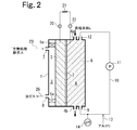
- FIG. 2 is a schematic cross-sectional view showing a schematic configuration of the microbial power generation method and apparatus of the present invention.
- the layered body 1 is partitioned into a positive electrode chamber 3 and a negative electrode chamber 4 by an ion-permeable non-conductive film 2.
- a positive electrode 5 is disposed in the positive electrode chamber 3 so as to be in contact with the ion-permeable nonconductive film 2.
- a negative electrode 6 made of a conductive porous material is disposed in the negative electrode chamber 4.
- the negative electrode 6 is in contact with the ion permeable non-conductive membrane 2 directly or through a microbial membrane of about 1 to 2 layers. If the ion permeable non-conductive membrane 2 is a cation permeable membrane, Proton (H + ) can be transferred from the negative electrode 6 to the ion-permeable non-conductive membrane 2.
- the inside of the positive electrode chamber 3 is an empty chamber, and an oxygen-containing gas (in this embodiment, an aerobic biological treatment exhaust gas) is introduced from the gas inlet 7, and the exhaust gas flows out from the gas outlet 8 through the exhaust pipe 25. .
- an oxygen-containing gas in this embodiment, an aerobic biological treatment exhaust gas
- a cation permeable membrane is suitable as described later, but other materials may be used.
- Microorganisms are supported on the negative electrode 6 made of a porous material.
- the negative electrode solution 4 is introduced into the negative electrode chamber 4 from the inlet 4a, and the waste liquid is discharged from the outlet 4b.
- the inside of the negative electrode chamber 4 is anaerobic.
- the negative electrode solution L in the negative electrode chamber 4 is circulated through the circulation outlet 9, the circulation pipe 10, the circulation pump 11, and the circulation return port 12.
- the circulation pipe 10 is provided with a pH meter 14 for measuring the pH of the liquid flowing out from the negative electrode chamber 4, and connected with an alkali addition pipe 13 such as an aqueous sodium hydroxide solution, so that the pH of the negative electrode solution L is 7 An alkali is added as necessary so that it becomes ⁇ 9.
- the condensed water generated in the positive electrode chamber 3 is drained from a condensed water outlet (not shown).
- the aerobic biological treatment exhaust gas containing oxygen, carbon dioxide gas and water vapor is passed through the positive electrode chamber 3, and the negative electrode solution L is circulated by operating the pump 11 as necessary.
- the reaction proceeds.
- This electron e ⁇ flows to the positive electrode 5 through the negative electrode 6, the terminal 22, the external resistor 21, and the terminal 20.
- Proton H + generated by the above reaction moves to the positive electrode 5 through the cation permeable membrane of the ion permeable nonconductive membrane 5A.
- O 2 + 4H + + 4e ⁇ ⁇ 2H 2 O The reaction proceeds.
- H 2 O produced by this positive electrode reaction is condensed to produce condensed water.
- K + , Na + and the like that have permeated through the cation permeable membrane of the ion permeable non-conductive membrane 2 are dissolved, so that in the conventional microbial power generation device that ventilates air as an oxygen-containing gas.
- the condensed water has a high alkalinity of about pH 9.5 to 12.5.
- the pH of this condensed water is 7.5 by neutralization with carbon dioxide gas. ⁇ 9 or so.
- alkali is added to the negative electrode solution L so that the pH detected by the pH meter 14 is preferably 7-9.
- This alkali may be added directly to the negative electrode chamber 6, but by adding it to the circulating water, the entire area in the negative electrode chamber 6 can be maintained at a pH of 7 to 9 without partial bias.
- FIG. 1 is a schematic cross-sectional view of a microbial power generation apparatus according to a particularly preferred embodiment of the present invention.
- two ion-permeable non-conductive membranes 31 and 31 are arranged in parallel to each other in a substantially rectangular parallelepiped tank 30 so that the ion permeation can be achieved.
- a negative electrode chamber 32 is formed between the conductive nonconductive films 31 and 31, and two positive electrode chambers 33 and 33 are formed by separating the negative electrode chamber 32 and the ion permeable nonconductive film 31 from each other. .
- a negative electrode 34 made of a porous material is disposed in the negative electrode chamber 32 so as to be in contact with each ion-permeable non-conductive film 31 directly or through a biofilm of about one to two layers.
- the negative electrode 34 is preferably pressed lightly against the ion-permeable non-conductive films 31 and 31 with a pressure of 0.1 kg / cm 2 or less, for example.
- a positive electrode 35 is disposed in contact with the ion permeable non-conductive film 31.
- the positive electrode 35 is pressed against the ion permeable non-conductive film 31 by being pressed by the packing 36.
- both may be welded or bonded with an adhesive.
- a distribution space for biological treatment exhaust gas introduced as an oxygen-containing gas is a distribution space for biological treatment exhaust gas introduced as an oxygen-containing gas.
- the positive electrode 35 and the negative electrode 34 are connected to an external resistor 38 via terminals 37 and 39.
- the negative electrode solution L is introduced into the negative electrode chamber 32 from the inlet 32a, and the waste liquid flows out from the outlet 32b.
- the inside of the negative electrode chamber 32 is anaerobic.
- the negative electrode solution in the negative electrode chamber 32 is circulated through the circulation outlet 41, the circulation pipe 42, the circulation pump 43 and the circulation return port 44.
- the oxygen-containing gas from the pipe 62 flows in from the gas inlet 51, and the exhaust gas flows out of the gas outlet 52 through the pipe 63.
- an aerobic biological treatment exhaust gas is used as the oxygen-containing gas.
- a negative electrode solution circulation pipe 42 is provided with a pH meter 47 and an alkali addition pipe 45 is connected thereto.
- the pH of the negative electrode solution flowing out from the negative electrode chamber 32 is detected by a pH meter 47, and an alkali such as an aqueous sodium hydroxide solution is added so that this pH is preferably 7-9.
- an aerobic biological treatment exhaust gas containing oxygen, carbon dioxide gas and water vapor is circulated in the positive electrode chamber 33, and the negative electrode solution is circulated in the negative electrode chamber 32, preferably the negative electrode solution is circulated.
- a potential difference is generated between the positive electrode 35 and the negative electrode 34, and a current flows through the external resistor 38.
- the microorganism that produces electric energy by being contained in the negative electrode solution L is not particularly limited as long as it has a function as an electron donor.
- sludge containing such microorganisms activated sludge obtained from biological treatment tanks that treat organic matter-containing water such as sewage, microorganisms contained in effluent from the first sedimentation basin of sewage, anaerobic digested sludge, etc.
- the microorganism can be held in the negative electrode by supplying to the chamber.
- the amount of microorganisms retained in the negative electrode chamber is preferably high, and for example, the microorganism concentration is preferably 1 to 50 g / L.
- the negative electrode solution L a solution that holds microorganisms or cells and has a composition necessary for power generation is used.
- the negative electrode side solution includes energy required for metabolism in the respiratory system such as bouillon medium, M9 medium, L medium, Malt Extract, MY medium, and nitrifying bacteria selection medium.
- a medium having a composition such as a source and nutrients can be used.
- organic waste such as sewage, organic industrial wastewater, and garbage can be used.
- the negative electrode solution L may contain an electron mediator in order to make it easier to extract electrons from microorganisms or cells.
- the electron mediator include compounds having a thionin skeleton such as thionine, dimethyldisulfonated thionine, new methylene blue and toluidine blue-O, and 2-hydroxy-1,4-naphthoquinone such as 2-hydroxy-1,4-naphthoquinone.
- Examples include compounds having a skeleton, brilliant cresyl blue, garocyanine, resorufin, alizarin brilliant blue, phenothiazinone, phenazine esosulphate, safranin-O, dichlorophenolindophenol, ferrocene, benzoquinone, phthalocyanine, or benzyl viologen and their derivatives. be able to.
- the negative electrode solution L may contain a phosphate buffer as necessary.
- the negative electrode solution L contains an organic substance.
- the organic substance is not particularly limited as long as it can be decomposed by microorganisms. For example, water-soluble organic substances, organic fine particles dispersed in water, and the like are used.
- the negative electrode solution may be organic wastewater such as sewage and food factory effluent.
- the organic substance concentration in the negative electrode solution L is preferably as high as about 100 to 10,000 mg / L in order to increase the power generation efficiency.
- the biological treatment exhaust gas distributed to the positive electrode chamber may be an aerobic biological treatment exhaust gas containing oxygen, carbon dioxide gas and water vapor, or an anaerobic biological treatment exhaust gas containing carbon dioxide gas and water vapor.
- composition of these biological treatment exhaust gas varies widely depending on the location where it is generated, but normally, in an aerobic biological treatment exhaust gas, the O 2 concentration: 15 to 19 vol%, the CO 2 concentration 1 to 5 vol%
- the anaerobic biological treatment exhaust gas has a CO 2 concentration of 20 to 40% by weight and a humidity of 95 to 100%.
- the present invention can also be carried out by further supplying carbon dioxide gas and water vapor to the oxygen-containing gas in a microbial power generation apparatus that supplies an oxygen-containing gas such as air to the positive electrode chamber.
- the gas can be supplied as saturated vapor pressure at that temperature by aeration of the gas supplied to the positive electrode chamber by aeration in a water tank.
- exhaust gas from the positive electrode chamber may be deoxygenated as necessary and then vented to the negative electrode chamber to be used for purging dissolved oxygen from the negative electrode solution L.
- the ion permeable non-conductive membrane may be any ion permeable membrane such as a non-conductive and ion permeable cation permeable membrane or anion permeable membrane, and various ion exchange membranes and reverse osmosis membranes may be used.
- a cation exchange membrane having a high proton selectivity or an anion exchange membrane can be suitably used.
- the cation exchange membrane Nafion (registered trademark) manufactured by DuPont Co., Ltd. or a cation exchange membrane manufactured by Astom Co., Ltd.
- a CMB film or the like can be used.
- an anion exchange membrane As an anion exchange membrane, an anion exchange membrane made by Astom, an anion electrolyte membrane made by Tokuyama, etc. are suitable.
- the ion-permeable non-conductive film is preferably thin and strong. Usually, the film thickness is preferably about 30 to 300 ⁇ m, particularly about 30 to 200 ⁇ m. It is preferable to use a cation exchange membrane as the ion permeable non-conductive membrane because the carbon dioxide gas introducing effect of the present invention is effectively exhibited. Moreover, it is preferable to use an anion exchange membrane from the surface of the improvement effect of ion permeability by water vapor.
- the negative electrode is preferably a porous body having a large surface area, a large number of voids, and water permeability so that many microorganisms can be retained.
- Specific examples include a conductive material sheet having a roughened surface and a porous conductor (for example, graphite felt, expanded titanium, expanded stainless steel, etc.) in which the conductive material is made into a felt-like porous sheet. .
- a plurality of sheet-like conductors may be laminated to form a negative electrode.
- the same kind of conductor sheets may be laminated, or different kinds of conductor sheets (for example, a graphite sheet having a rough surface and a graphite felt) may be laminated.
- the total thickness of the negative electrode is preferably 3 mm or more and 40 mm or less, particularly about 5 to 20 mm.
- a negative electrode is constituted by a laminated sheet, it is preferable to orient the laminated surface in a direction connecting the liquid inlet and outlet so that the liquid flows along a mating surface (laminated surface) between the sheets.
- the negative electrode chamber may be divided into a plurality of compartments, and the pH of the liquid in the negative electrode compartment may be adjusted after suppressing the pH drop in each compartment by connecting the compartments in series. If the negative electrode chamber is divided, the amount of organic matter decomposition in each of the compartments is reduced, and as a result, the amount of carbon dioxide gas produced is also reduced, so that the pH drop in each of the compartments can be reduced.
- the positive electrode preferably has a conductive base material and an oxygen reduction catalyst supported on the conductive base material.
- any material may be used as long as it has high electrical conductivity, high corrosion resistance, sufficient electrical conductivity and corrosion resistance even when the thickness is small, and further has mechanical strength as the conductive base material.
- graphite paper, graphite felt, graphite cloth, stainless mesh, titanium mesh, etc. can be used. Of these, graphite paper, graphite felt, graphite cloth, etc., particularly in terms of durability and ease of processing.
- a graphite-based substrate such as graphite is preferable, and graphite paper is particularly preferable.
- These graphite base materials may be those made hydrophobic by a fluororesin such as polytetrafluoroethylene (PTFE).
- the thickness of the conductive base material of the positive electrode is about 20 to 3000 ⁇ m because oxygen permeation deteriorates if it is too thick, and if it is too thin, required properties such as strength required for the base material cannot be satisfied. Is preferred.
- oxygen reduction catalyst in addition to noble metals such as platinum, metal oxides such as manganese dioxide are preferred because they are inexpensive and have good catalytic activity, and the supported amount is 0.01 to 2.0 mg / it is preferable that the cm 2.
- a negative electrode was formed by stacking and filling two 1 cm thick graphite felts into a 7 cm ⁇ 25 cm ⁇ 2 cm (thickness) negative electrode chamber.
- a positive electrode chamber was formed on the negative electrode through a cation exchange membrane (trade name (registered trademark) “Nafion 115” manufactured by DuPont Co., Ltd.) as an ion-permeable non-conductive membrane.
- the positive electrode chamber has a size of 7 cm ⁇ 25 cm ⁇ 0.5 cm (thickness), a Pt catalyst (Pt-supported carbon black, Pt content 50% by weight) manufactured by Tanaka Kikinzoku Co., Ltd., and a 5% Nafion (registered trademark) solution (DuPont).
- the liquid dispersed in PTFE was applied to a 160 ⁇ m thick carbon paper (manufactured by Toyo Carbon Co., Ltd.) treated with PTFE to make the Pt adhesion amount 0.4 mg / cm 2, and dried at 50 ° C.
- the product obtained as described above was used as a positive electrode and adhered to the cation exchange membrane.
- a stainless steel wire was bonded to the negative electrode graphite felt and the positive electrode carbon paper with a conductive paste to form an electrical lead wire and connected with a resistance of 2 ⁇ .
- the pH was maintained at 7.5, and a negative electrode solution containing 1000 mg / L of acetic acid, phosphoric acid and ammonia was passed.
- This negative electrode solution was previously heated to 35 ° C. in a separate water tank, and the temperature of the negative electrode chamber was increased to 35 ° C. by passing the liquid heated in this water tank through the negative electrode chamber at 10 mL / min.
- the effluent of another microbial power generation device was passed as an inoculum.
- the positive electrode chamber was aerated with normal temperature dry air at a flow rate of 0.5 L / min. As a result, the power generation amount became almost constant three days after the start of the flow of the negative electrode solution, and the power generation amount per 1 m 3 of the negative electrode was 140 W (power generation efficiency 140 W / m 3 ).
- Comparative Example 2 In Comparative Example 1, power was generated in the same manner except that carbon dioxide was introduced into the air supplied to the positive electrode chamber from a carbon dioxide cylinder at 1 mL / min (0.2% with respect to air). The power generation efficiency began to improve further, and the power generation efficiency became 180 W / m 3 after 5 minutes.
- Example 1 In Comparative Example 2, the air supplied to the positive electrode chamber was introduced into a 2 L sealed water tank containing 1.5 L of pure water, aerated for 4 minutes, and then introduced into the positive electrode chamber together with carbon dioxide gas. When power generation was performed, the power generation efficiency increased to 210 W / m 3 . In Example 1, air was aerated in a water tank, so that the air humidity was 97%.
- Example 2 In Comparative Example 1, instead of air, aerobic biological treatment exhaust gas in a laboratory wastewater treatment plant (fluidized bed biological treatment tank with a capacity of 40 m 3 , BOD load 0.5 kg / m 3 ⁇ day exhaust gas (O 2 concentration: 19.8% by volume, CO 2 concentration: 1.3% by volume, and humidity 99%) were generated in the same manner except that the positive electrode chamber was ventilated. As a result, a power generation efficiency of 255 W / m 3 was obtained.
- a laboratory wastewater treatment plant fluidized bed biological treatment tank with a capacity of 40 m 3 , BOD load 0.5 kg / m 3 ⁇ day exhaust gas (O 2 concentration: 19.8% by volume, CO 2 concentration: 1.3% by volume, and humidity 99%) were generated in the same manner except that the positive electrode chamber was ventilated.
- a power generation efficiency of 255 W / m 3 was obtained.
- Example 3 In Comparative Example 1, instead of air, a UASB apparatus (10 cm diameter, 60 cm height, synthetic substrate of methanol, load 30 kg-COD Cr / m 3 / day) biobus (CO 2 concentration 32 vol%, humidity 99%) ) When power generation was performed in the same manner except that a mixed gas of 200 mL / min and 400 mL / min of air was passed through the positive electrode chamber, a power generation efficiency of 248 W / m 3 was obtained.
- the power generation efficiency can be improved by introducing carbon dioxide gas and water vapor into the oxygen-containing gas supplied to the positive electrode chamber, or by using biological treatment exhaust gas as the oxygen-containing gas.
Landscapes
- Chemical & Material Sciences (AREA)
- Life Sciences & Earth Sciences (AREA)
- Engineering & Computer Science (AREA)
- Organic Chemistry (AREA)
- Biochemistry (AREA)
- Zoology (AREA)
- Wood Science & Technology (AREA)
- Health & Medical Sciences (AREA)
- Bioinformatics & Cheminformatics (AREA)
- Sustainable Development (AREA)
- Microbiology (AREA)
- Chemical Kinetics & Catalysis (AREA)
- General Chemical & Material Sciences (AREA)
- General Engineering & Computer Science (AREA)
- General Health & Medical Sciences (AREA)
- Genetics & Genomics (AREA)
- Manufacturing & Machinery (AREA)
- Electrochemistry (AREA)
- Sustainable Energy (AREA)
- Biotechnology (AREA)
- Medicinal Chemistry (AREA)
- Biomedical Technology (AREA)
- Water Treatment By Electricity Or Magnetism (AREA)
- Fuel Cell (AREA)
- Apparatus Associated With Microorganisms And Enzymes (AREA)
- Preparation Of Compounds By Using Micro-Organisms (AREA)
- Separation Using Semi-Permeable Membranes (AREA)
Abstract
Description
1)負極のメディエーター(例えば特許文献3)
2)負極室のpH調整
3)正極触媒の種類や触媒活性成分の担持方法
4)正極の形状
などについての検討がなされている。
本発明は、簡易かつ安価な手段で微生物発電装置の発電効率を向上させることができる微生物発電方法及び微生物発電装置を提供することを目的とする。
そして、この先願の発明に基き、更に検討した結果、正極室に供給する酸素含有ガスに更に水蒸気を導入することにより、より一層発電効率を高めることができることを見出した。
この水蒸気による発電効率の向上効果の作用機構の詳細は明らかではないが、水蒸気が、イオン透過性非導電性膜のイオン透過を促進することが推定される。即ち、イオン交換膜等のイオン透過性非導電性膜は、水分含有率によってイオン透過性が変化することが知られており、水分量が少ないとイオン透過性が低下する。特に、イオン透過性非導電性膜としてアニオン交換膜を使用する場合、生物発電でのイオンの透過には、正極での水の解離が必要であり、正極室への一定量の水の供給がイオンの透過のみならず、水酸イオンの生成にも有効に作用すると考えられる。従って、正極室への水蒸気の導入は、この正極での水の解離のために有効となる。
特に、活性汚泥曝気槽のpHを中性から弱酸性で運転した場合、排ガスの炭酸ガス濃度が高くなり、正極室に供給するガスとして好適である。
また、近年、省エネを目的に適用が広まっている微細気泡散気管等、酸素溶解効率の高い散気装置を使用すると、排ガス中の炭酸ガス濃度が高くなり、より好ましい。
一方、嫌気性生物処理排ガスは酸素を含まないが、炭酸ガス濃度が高く、また、高湿で水蒸気量も高い。従って、嫌気性生物処理排ガスであっても、空気等の酸素含有ガスと混合して用いることにより、正極室供給ガスとして有効に用いることができる。
しかして、生物処理排ガスを排出する生物処理設備は、廃水や有機性廃棄物をエネルギー源とする生物発電を実施する現場には、ほとんどの場合、生物発電設備に近接して併設されることから、ガスの輸送という面でも有利である。
(有機物)+H2O→CO2+H++e-
なる反応が進行する。この電子e-が負極6、端子22、外部抵抗21、端子20を経て正極5へ流れる。
O2+4H++4e-→2H2O
なる反応が進行する。この正極反応で生成したH2Oは凝縮して凝縮水が生じる。この凝縮水には、イオン透過性非導電性膜2のカチオン透過膜を透過してきたK+,Na+などが溶け込み、これにより酸素含有ガスとして空気を通気する従来の微生物発電装置にあっては、凝縮水がpH9.5~12.5程度の高アルカリ性となるが、本発明では炭酸ガスを含む生物処理排ガスを通気するため、炭酸ガスによる中和作用でこの凝縮水のpHは7.5~9程度となる。
前述の如く、pH中性~弱酸性で運転している活性汚泥曝気槽からの排ガスは炭酸ガス濃度が高く、好適である。また、近年、省エネを目的に適用が広まっている微細気泡散気管等、酸素溶解効率の高い散気装置を使用している曝気槽の排ガスも炭酸ガス濃度が高く、好ましい。
イオン透過性非導電性膜としてはカチオン交換膜を用いることが、本発明による炭酸ガスの導入効果が有効に発揮され好ましい。また、水蒸気によるイオン透過性の向上効果の面からは、アニオン交換膜を用いることが好ましい。
説明の便宜上まず比較例を挙げる。
7cm×25cm×2cm(厚さ)の負極室に、厚さ1cmのグラファイトフェルトを2枚重ねて充填して負極を形成した。この負極に対して、イオン透過性非導電性膜としてカチオン交換膜(デュポン株式会社製 商品名(登録商標)「ナフィオン115」)を介して正極室を形成した。正極室は7cm×25cm×0.5cm(厚さ)であり、田中貴金属社製Pt触媒(Pt担持カーボンブラック,Pt含有量50重量%)を、5重量%ナフィオン(登録商標)溶液(デュポン社製)に分散させた液を、PTFEで撥水処理した厚さ160μmのカーボンペーパー(東洋カーボン社製)に、Pt付着量が0.4mg/cm2となるように塗布し、50℃で乾燥させて得られたものを正極として、上記カチオン交換膜と密着させた。
負極のグラファイトフェルトと正極のカーボンペーパーには、ステンレス線を導電性ペーストで接着して電気引出し線とし、2Ωの抵抗で接続した。
正極室には、常温の乾燥空気を0.5L/minの流量で通気した。
その結果、負極溶液の通液開始から3日後には発電量はほぼ一定となり、負極1m3あたりの発電量は140W(発電効率140W/m3)となった。
比較例1において、正極室に供給する空気に、炭酸ガスボンベから炭酸ガスを1mL/min(空気に対して0.2%)導入したこと以外は同様にして発電を行ったところ、炭酸ガス導入直後より発電効率は向上しはじめ、5分後には発電効率180W/m3となった。
比較例2において、正極室に供給する空気を、純水1.5Lを入れた2Lの密閉水槽に導入し、4分間曝気した後、炭酸ガスと共に、正極室に導入したこと以外は同様にして発電を行ったところ、発電効率は210W/m3に増加した。なお、この実施例1において、空気を水槽で曝気したことにより、空気の湿度は97%となった。
比較例1において、空気の代りに、研究所廃水処理場における好気性生物処理排ガス(容量40m3の流動床式生物処理槽、BOD負荷0.5kg/m3・日の排ガス(O2濃度:19.8容量%、CO2濃度:1.3容量%、湿度99%)を正極室に通気したこと以外は同様にして発電を行ったところ、発電効率255W/m3が得られた。
比較例1において、空気の代りに、UASB装置(10cm径、60cm高さ、メタノールの合成基質、負荷30kg-CODCr/m3/日)のバイオバス(CO2濃度32容量%、湿度99%)200mL/minと空気400mL/minとの混合ガスを正極室に通気したこと以外は同様にして発電を行ったところ、発電効率248W/m3が得られた。
なお、本出願は、2008年12月24日付で出願された日本特許出願(特願2008-327988)に基づいており、その全体が引用により援用される。
2,31 イオン透過性非導電性膜
3,33 正極室
4,32 負極室
5,35 正極
6,34 負極
Claims (10)
- 負極を有し、微生物及び電子供与体を含む液を保持する負極室と、
該負極室に対しイオン透過性非導電性膜を介して隔てられており、該イオン透過性非導電性膜に接する正極を有する正極室と
を備えた微生物発電装置の該正極室に酸素含有ガスを供給して発電を行う微生物発電方法において、
該酸素含有ガスが生物処理排ガスを含むことを特徴とする微生物発電方法。 - 請求項1において、該酸素含有ガスとして好気性生物処理排ガスを正極室に供給することを特徴とする微生物発電方法。
- 請求項1において、該酸素含有ガスとして空気と嫌気性生物処理排ガスとを該正極室に供給することを特徴とする微生物発電方法。
- 負極を有し、微生物及び電子供与体を含む液を保持する負極室と、
該負極室に対しイオン透過性非導電性膜を介して隔てられており、該イオン透過性非導電性膜に接する正極を有する正極室と
を備えた微生物発電装置の該正極室に酸素含有ガスを供給して発電を行う微生物発電方法において、
該正極室に供給される酸素含有ガスに炭酸ガスと水蒸気を導入することを特徴とする微生物発電方法。 - 請求項4において、該正極室に、空気を水槽に通気して曝気した後、炭酸ガスと共に導入することを特徴とする微生物発電方法。
- 負極を有し、微生物及び電子供与体を含む液を保持する負極室と、
該負極室に対しイオン透過性非導電性膜を介して隔てられており、該イオン透過性非導電性膜に接する正極を有する正極室と、
該正極室に酸素含有ガスを供給する手段と
を備えた微生物発電装置において、
該正極室に生物処理排ガスを導入する手段を設けたことを特徴とする微生物発電装置。 - 請求項6において、該正極室に好気性生物処理排ガスを導入する手段を有することを特徴とする微生物発電装置。
- 請求項6において、該正極室に空気と嫌気性生物処理排ガスとを導入する手段を有することを特徴とする微生物発電装置。
- 負極を有し、微生物及び電子供与体を含む液を保持する負極室と、
該負極室に対しイオン透過性非導電性膜を介して隔てられており、該イオン透過性非導電性膜に接する正極を有する正極室と、
該正極室に酸素含有ガスを供給する手段と
を備えた微生物発電装置において、
該正極室に供給される酸素含有ガスに炭酸ガスと水蒸気を導入する手段を設けたことを特徴とする微生物発電装置。 - 請求項9において、該正極室に供給される酸素含有ガスに炭酸ガスと水蒸気を導入する手段が、空気を水槽に通気して曝気した後、炭酸ガスと共に該正極室に導入する手段であることを特徴とする微生物発電装置。
Priority Applications (5)
| Application Number | Priority Date | Filing Date | Title |
|---|---|---|---|
| EP20090834710 EP2372826A4 (en) | 2008-12-24 | 2009-12-09 | MICROBIAL POWER GENERATOR AND MICROBIAL GENERATOR |
| KR1020117012851A KR101697144B1 (ko) | 2008-12-24 | 2009-12-09 | 미생물 발전 방법 및 미생물 발전 장치 |
| US12/998,964 US9209475B2 (en) | 2008-12-24 | 2009-12-09 | Method for microbially generating electricity and microbial power generator |
| CN200980150669.6A CN102257666B (zh) | 2008-12-24 | 2009-12-09 | 微生物发电方法和微生物发电装置 |
| US14/718,480 US9337507B2 (en) | 2008-12-24 | 2015-05-21 | Microbial power generator |
Applications Claiming Priority (2)
| Application Number | Priority Date | Filing Date | Title |
|---|---|---|---|
| JP2008-327988 | 2008-12-24 | ||
| JP2008327988A JP5428328B2 (ja) | 2008-12-24 | 2008-12-24 | 微生物発電方法及び微生物発電装置 |
Related Child Applications (2)
| Application Number | Title | Priority Date | Filing Date |
|---|---|---|---|
| US12/998,964 A-371-Of-International US9209475B2 (en) | 2008-12-24 | 2009-12-09 | Method for microbially generating electricity and microbial power generator |
| US14/718,480 Division US9337507B2 (en) | 2008-12-24 | 2015-05-21 | Microbial power generator |
Publications (1)
| Publication Number | Publication Date |
|---|---|
| WO2010073907A1 true WO2010073907A1 (ja) | 2010-07-01 |
Family
ID=42287523
Family Applications (1)
| Application Number | Title | Priority Date | Filing Date |
|---|---|---|---|
| PCT/JP2009/070592 Ceased WO2010073907A1 (ja) | 2008-12-24 | 2009-12-09 | 微生物発電方法及び微生物発電装置 |
Country Status (7)
| Country | Link |
|---|---|
| US (2) | US9209475B2 (ja) |
| EP (1) | EP2372826A4 (ja) |
| JP (1) | JP5428328B2 (ja) |
| KR (1) | KR101697144B1 (ja) |
| CN (1) | CN102257666B (ja) |
| TW (1) | TWI472091B (ja) |
| WO (1) | WO2010073907A1 (ja) |
Cited By (1)
| Publication number | Priority date | Publication date | Assignee | Title |
|---|---|---|---|---|
| JP2017069019A (ja) * | 2015-09-30 | 2017-04-06 | 国立大学法人 宮崎大学 | 微生物燃料電池を用いた発電方法 |
Families Citing this family (9)
| Publication number | Priority date | Publication date | Assignee | Title |
|---|---|---|---|---|
| JP2011049068A (ja) * | 2009-08-27 | 2011-03-10 | Mitsui Eng & Shipbuild Co Ltd | バイオ燃料電池 |
| US9303324B2 (en) * | 2012-07-26 | 2016-04-05 | Liquid Light, Inc. | Electrochemical co-production of chemicals with sulfur-based reactant feeds to anode |
| JP6254884B2 (ja) * | 2014-03-27 | 2017-12-27 | パナソニック株式会社 | 微生物燃料電池 |
| CN109716569A (zh) * | 2016-09-29 | 2019-05-03 | 松下电器产业株式会社 | 微生物燃料电池以及废液处理装置 |
| JP6890560B2 (ja) * | 2018-03-08 | 2021-06-18 | 栗田工業株式会社 | 微生物発電装置及び方法 |
| JP6652150B2 (ja) * | 2018-03-23 | 2020-02-19 | 栗田工業株式会社 | 微生物発電装置及びその運転方法 |
| CN109980258B (zh) * | 2019-02-21 | 2022-07-19 | 浙江海洋大学 | 弧菌作为海洋产电菌的产电方法 |
| JP7247713B2 (ja) * | 2019-03-29 | 2023-03-29 | 栗田工業株式会社 | 有機性排水の生物処理装置 |
| JP7404080B2 (ja) * | 2020-01-17 | 2023-12-25 | 住友重機械工業株式会社 | 排水処理装置及び排水処理方法並びに処理システム |
Citations (7)
| Publication number | Priority date | Publication date | Assignee | Title |
|---|---|---|---|---|
| JP2000133326A (ja) | 1998-10-30 | 2000-05-12 | Canon Inc | 生体代謝利用発電方法及び電池 |
| JP2004342412A (ja) | 2003-05-14 | 2004-12-02 | Ebara Corp | 有機性物質を利用する発電方法及び装置 |
| JP2006331706A (ja) | 2005-05-24 | 2006-12-07 | Ebara Corp | 生物発電用電子メディエーター、生物発電用アノード及びこれらを利用する発電方法及び発電装置 |
| JP2007505442A (ja) * | 2003-06-27 | 2007-03-08 | ザ ユニバーシティ オブ ウエスタン オンタリオ | バイオ燃料電池 |
| WO2007037261A1 (ja) * | 2005-09-28 | 2007-04-05 | Ebara Corporation | 生物発電装置及び該生物発電装置を利用する有機性固形汚濁物質含有廃棄物の処理方法、有機性高分子物質含有廃液の処理方法、有機性物質含有廃液の処理方法並びにこれらの処理方法を行う装置 |
| JP2009152097A (ja) * | 2007-12-21 | 2009-07-09 | Kurita Water Ind Ltd | 微生物発電方法および微生物発電装置 |
| JP2009231231A (ja) * | 2008-03-25 | 2009-10-08 | Kurita Water Ind Ltd | 微生物発電方法および装置 |
Family Cites Families (10)
| Publication number | Priority date | Publication date | Assignee | Title |
|---|---|---|---|---|
| US3284239A (en) * | 1963-06-03 | 1966-11-08 | Herbert F Hunger | Biochemical fuel cell |
| US5736026A (en) * | 1996-02-05 | 1998-04-07 | Energy Research Corporation | Biomass-fuel cell cogeneration apparatus and method |
| NL1020965C2 (nl) * | 2002-06-28 | 2004-01-13 | Tno | Biobrandstofcel. |
| JP4031740B2 (ja) * | 2003-07-15 | 2008-01-09 | 日東電工株式会社 | 燃料電池用セパレータ及びそれを用いた燃料電池 |
| CN100505403C (zh) * | 2004-10-15 | 2009-06-24 | 松下电器产业株式会社 | 燃料电池系统 |
| CN1949577A (zh) | 2005-10-14 | 2007-04-18 | 中国科学院过程工程研究所 | 生物反应器-直接微生物燃料电池及其用途 |
| FI20061064A0 (fi) * | 2006-06-19 | 2006-12-01 | Valtion Teknillinen | Uudet ohutkalvorakenteet |
| EP2000000A1 (en) * | 2007-06-07 | 2008-12-10 | Danmarks Tekniske Universitet | Microbial fuel cell |
| CN101242004A (zh) | 2008-03-14 | 2008-08-13 | 哈尔滨工业大学 | 一种利用好氧微生物作为阴极催化剂的mfc制备方法 |
| JP5287149B2 (ja) * | 2008-10-30 | 2013-09-11 | 栗田工業株式会社 | 微生物発電方法及び微生物発電装置 |
-
2008
- 2008-12-24 JP JP2008327988A patent/JP5428328B2/ja active Active
-
2009
- 2009-12-09 EP EP20090834710 patent/EP2372826A4/en not_active Withdrawn
- 2009-12-09 US US12/998,964 patent/US9209475B2/en not_active Expired - Fee Related
- 2009-12-09 KR KR1020117012851A patent/KR101697144B1/ko not_active Expired - Fee Related
- 2009-12-09 WO PCT/JP2009/070592 patent/WO2010073907A1/ja not_active Ceased
- 2009-12-09 CN CN200980150669.6A patent/CN102257666B/zh not_active Expired - Fee Related
- 2009-12-22 TW TW98144219A patent/TWI472091B/zh not_active IP Right Cessation
-
2015
- 2015-05-21 US US14/718,480 patent/US9337507B2/en active Active
Patent Citations (7)
| Publication number | Priority date | Publication date | Assignee | Title |
|---|---|---|---|---|
| JP2000133326A (ja) | 1998-10-30 | 2000-05-12 | Canon Inc | 生体代謝利用発電方法及び電池 |
| JP2004342412A (ja) | 2003-05-14 | 2004-12-02 | Ebara Corp | 有機性物質を利用する発電方法及び装置 |
| JP2007505442A (ja) * | 2003-06-27 | 2007-03-08 | ザ ユニバーシティ オブ ウエスタン オンタリオ | バイオ燃料電池 |
| JP2006331706A (ja) | 2005-05-24 | 2006-12-07 | Ebara Corp | 生物発電用電子メディエーター、生物発電用アノード及びこれらを利用する発電方法及び発電装置 |
| WO2007037261A1 (ja) * | 2005-09-28 | 2007-04-05 | Ebara Corporation | 生物発電装置及び該生物発電装置を利用する有機性固形汚濁物質含有廃棄物の処理方法、有機性高分子物質含有廃液の処理方法、有機性物質含有廃液の処理方法並びにこれらの処理方法を行う装置 |
| JP2009152097A (ja) * | 2007-12-21 | 2009-07-09 | Kurita Water Ind Ltd | 微生物発電方法および微生物発電装置 |
| JP2009231231A (ja) * | 2008-03-25 | 2009-10-08 | Kurita Water Ind Ltd | 微生物発電方法および装置 |
Non-Patent Citations (1)
| Title |
|---|
| See also references of EP2372826A4 |
Cited By (1)
| Publication number | Priority date | Publication date | Assignee | Title |
|---|---|---|---|---|
| JP2017069019A (ja) * | 2015-09-30 | 2017-04-06 | 国立大学法人 宮崎大学 | 微生物燃料電池を用いた発電方法 |
Also Published As
| Publication number | Publication date |
|---|---|
| CN102257666A (zh) | 2011-11-23 |
| JP2010153115A (ja) | 2010-07-08 |
| KR20110106293A (ko) | 2011-09-28 |
| KR101697144B1 (ko) | 2017-01-17 |
| CN102257666B (zh) | 2014-05-28 |
| EP2372826A1 (en) | 2011-10-05 |
| US9209475B2 (en) | 2015-12-08 |
| TW201034283A (en) | 2010-09-16 |
| US20110256427A1 (en) | 2011-10-20 |
| US20150255822A1 (en) | 2015-09-10 |
| EP2372826A4 (en) | 2014-04-02 |
| TWI472091B (zh) | 2015-02-01 |
| US9337507B2 (en) | 2016-05-10 |
| JP5428328B2 (ja) | 2014-02-26 |
Similar Documents
| Publication | Publication Date | Title |
|---|---|---|
| JP5428328B2 (ja) | 微生物発電方法及び微生物発電装置 | |
| JP5298589B2 (ja) | 微生物発電装置 | |
| JP5407156B2 (ja) | 微生物発電方法および微生物発電装置 | |
| JP5526505B2 (ja) | 微生物発電装置 | |
| JP5359725B2 (ja) | 微生物発電方法及び微生物発電装置 | |
| JP2009295488A (ja) | 微生物発電装置及び微生物発電装置用正極 | |
| WO2010071059A1 (ja) | 微生物発電方法及び微生物発電装置 | |
| JP6252702B1 (ja) | 微生物発電方法及び装置 | |
| JP5287149B2 (ja) | 微生物発電方法及び微生物発電装置 | |
| JP6358352B1 (ja) | 微生物発電装置及び微生物発電方法 | |
| WO2019171833A1 (ja) | 微生物発電装置及び方法 | |
| JP2010102953A (ja) | 微生物発電装置及び微生物発電装置用正極 | |
| JP5369700B2 (ja) | 微生物発電方法及び微生物発電装置 | |
| JP2019160459A (ja) | 微生物発電装置の運転方法 | |
| JP2018163750A (ja) | 微生物発電方法及び装置 | |
| JP2009238558A (ja) | 微生物発電方法および装置 | |
| JP2019169282A (ja) | 殺菌剤を用いる微生物発電装置及び微生物発電装置の運転方法 |
Legal Events
| Date | Code | Title | Description |
|---|---|---|---|
| WWE | Wipo information: entry into national phase |
Ref document number: 200980150669.6 Country of ref document: CN |
|
| 121 | Ep: the epo has been informed by wipo that ep was designated in this application |
Ref document number: 09834710 Country of ref document: EP Kind code of ref document: A1 |
|
| ENP | Entry into the national phase |
Ref document number: 20117012851 Country of ref document: KR Kind code of ref document: A |
|
| WWE | Wipo information: entry into national phase |
Ref document number: 12998964 Country of ref document: US |
|
| NENP | Non-entry into the national phase |
Ref country code: DE |
|
| REEP | Request for entry into the european phase |
Ref document number: 2009834710 Country of ref document: EP |
|
| WWE | Wipo information: entry into national phase |
Ref document number: 2009834710 Country of ref document: EP |