WO2010074031A1 - X線検査方法およびx線検査装置 - Google Patents
X線検査方法およびx線検査装置 Download PDFInfo
- Publication number
- WO2010074031A1 WO2010074031A1 PCT/JP2009/071244 JP2009071244W WO2010074031A1 WO 2010074031 A1 WO2010074031 A1 WO 2010074031A1 JP 2009071244 W JP2009071244 W JP 2009071244W WO 2010074031 A1 WO2010074031 A1 WO 2010074031A1
- Authority
- WO
- WIPO (PCT)
- Prior art keywords
- ray
- inspection
- focal position
- image
- partial
- Prior art date
- Legal status (The legal status is an assumption and is not a legal conclusion. Google has not performed a legal analysis and makes no representation as to the accuracy of the status listed.)
- Ceased
Links
Images


Classifications
-
- G—PHYSICS
- G01—MEASURING; TESTING
- G01N—INVESTIGATING OR ANALYSING MATERIALS BY DETERMINING THEIR CHEMICAL OR PHYSICAL PROPERTIES
- G01N23/00—Investigating or analysing materials by the use of wave or particle radiation, e.g. X-rays or neutrons, not covered by groups G01N3/00 – G01N17/00, G01N21/00 or G01N22/00
- G01N23/02—Investigating or analysing materials by the use of wave or particle radiation, e.g. X-rays or neutrons, not covered by groups G01N3/00 – G01N17/00, G01N21/00 or G01N22/00 by transmitting the radiation through the material
- G01N23/04—Investigating or analysing materials by the use of wave or particle radiation, e.g. X-rays or neutrons, not covered by groups G01N3/00 – G01N17/00, G01N21/00 or G01N22/00 by transmitting the radiation through the material and forming images of the material
- G01N23/046—Investigating or analysing materials by the use of wave or particle radiation, e.g. X-rays or neutrons, not covered by groups G01N3/00 – G01N17/00, G01N21/00 or G01N22/00 by transmitting the radiation through the material and forming images of the material using tomography, e.g. computed tomography [CT]
-
- H—ELECTRICITY
- H01—ELECTRIC ELEMENTS
- H01J—ELECTRIC DISCHARGE TUBES OR DISCHARGE LAMPS
- H01J35/00—X-ray tubes
- H01J35/02—Details
- H01J35/04—Electrodes ; Mutual position thereof; Constructional adaptations therefor
- H01J35/08—Anodes; Anti cathodes
- H01J35/112—Non-rotating anodes
-
- H—ELECTRICITY
- H01—ELECTRIC ELEMENTS
- H01J—ELECTRIC DISCHARGE TUBES OR DISCHARGE LAMPS
- H01J35/00—X-ray tubes
- H01J35/02—Details
- H01J35/14—Arrangements for concentrating, focusing, or directing the cathode ray
- H01J35/153—Spot position control
-
- G—PHYSICS
- G01—MEASURING; TESTING
- G01N—INVESTIGATING OR ANALYSING MATERIALS BY DETERMINING THEIR CHEMICAL OR PHYSICAL PROPERTIES
- G01N2223/00—Investigating materials by wave or particle radiation
- G01N2223/40—Imaging
- G01N2223/419—Imaging computed tomograph
-
- G—PHYSICS
- G01—MEASURING; TESTING
- G01N—INVESTIGATING OR ANALYSING MATERIALS BY DETERMINING THEIR CHEMICAL OR PHYSICAL PROPERTIES
- G01N2223/00—Investigating materials by wave or particle radiation
- G01N2223/60—Specific applications or type of materials
- G01N2223/611—Specific applications or type of materials patterned objects; electronic devices
- G01N2223/6113—Specific applications or type of materials patterned objects; electronic devices printed circuit board [PCB]
-
- H—ELECTRICITY
- H01—ELECTRIC ELEMENTS
- H01J—ELECTRIC DISCHARGE TUBES OR DISCHARGE LAMPS
- H01J2235/00—X-ray tubes
- H01J2235/08—Targets (anodes) and X-ray converters
- H01J2235/086—Target geometry
Definitions
- the present invention relates to an X-ray inspection method and an X-ray inspection apparatus.
- the present invention relates to an imaging method for inspecting an object using X-ray irradiation, and relates to a technique applicable to an X-ray inspection method and an X-ray inspection apparatus.
- LSI Large-Scale Integration
- BGAs All Grid Arrays
- CSPs CSPs
- QFPs Quad Flat Packages
- PGAs Peripheral Component Interconnects
- An LSI in a (Chip Size Package) package is used.
- BGA packages are used even for devices that require ultra-miniaturization, such as mobile phones, even though the number of pins is not so great.
- BGA and CSP packages of LSI greatly contribute to microminiaturization, they are characterized in that solder parts and the like are invisible from the appearance after assembly. Therefore, when inspecting a printed circuit board or the like on which a BGA or CSP package is mounted, quality evaluation has been performed by analyzing a fluoroscopic image obtained by irradiating the inspection object with X-rays. In the quality determination, X-ray CT (Computed Tomography) which reconstructs three-dimensional data of an object from fluoroscopic images taken from a plurality of directions is widely used.
- Patent Document 1 Japanese Patent Application Laid-Open No. 2007-127668
- Patent Document 1 Japanese Patent Application Laid-Open No. 2007-127668
- Patent Document 2 Japanese Patent Application Laid-Open No. 2006-177760 discloses a method of imaging a substrate with a plurality of detectors disposed discretely. Since imaging is performed by a plurality of detectors, the number of movements of the substrate can be reduced.
- JP 2007-127668 A Unexamined-Japanese-Patent No. 2006-177760
- Patent Document 1 shows an example of obtaining nine images for each region of interest.
- the direction in which imaging can be performed and the number of imagings are determined by the arrangement of the detectors.
- the present invention has been made to solve the above-mentioned problems, and an object of the present invention is to provide an X-ray inspection method and an X-ray inspection apparatus capable of performing CT reconstruction at high speed.
- the X-ray source outputs X-rays that have been transmitted through the inspection target area of the object by the X-ray detection unit, and the image indicated by the detected X-rays
- an X-ray examination method for reconstructing three-dimensional data.
- each of the plurality of partial regions is output from the detection result of the X-ray transmitted from the X-ray source from the X-ray focal position and the plurality of partial regions obtained by dividing the inspection target region in the first direction.
- the region to be inspected is divided into a plurality of partial regions with respect to a first direction and a second direction intersecting the first direction, and the repeating step includes repeating the first X-ray focal position of the X-ray source.
- the object is moved in the second direction, and from the state in which the object is moved in the second direction, the partial image is scanned while scanning the X-ray focal position of the X-ray source in the first direction. Including repeating the obtaining step.
- the X-ray focal position is scanned on a plurality of lines.
- the x-ray source comprises a plurality of targets respectively arranged on a plurality of lines, and in the step of repeating scanning the x-ray focal position on each target.
- the X-ray detection unit is disposed so as to be sandwiched between two targets in the direction intersecting the line.
- each target is a reflective target.
- an X-ray examination apparatus for reconstructing three-dimensional data of an examination area of an object.
- the X-ray inspection apparatus includes an X-ray source that outputs an X-ray, an X-ray detection unit that detects an X-ray and outputs an image represented by the detected X-ray, and a control unit that controls the operation of the X-ray inspection apparatus including.
- the control unit outputs from the X-ray focal position of the X-ray source, and detects X-rays transmitted through the plurality of partial areas obtained by dividing the inspection target area in the first direction.
- An image acquisition unit for acquiring a partial image
- an X-ray source control unit for causing the X-ray source to scan the X-ray focal position in a first direction
- a scan of the X-ray focal position by the X-ray source control unit includes a reconstruction unit for reconstructing three-dimensional data from the partial image acquired by the image acquisition unit at each of the plurality of X-ray focal positions.
- the focal position of the X-ray is scanned, and of the images captured by the X-ray inspection apparatus, an image of a portion corresponding to the X-ray output from each focal position and transmitted through the inspection target area is used. , Reconstruct three-dimensional data of the inspection target area. Therefore, according to the present invention, X-ray fluoroscopic images of the examination object from a plurality of directions necessary for CT reconstruction can be acquired at high speed. Therefore, according to the present invention, CT reconstruction can be performed at high speed.
- FIG. 1 is a schematic block diagram of an X-ray inspection apparatus according to a first embodiment. It is a figure for demonstrating the structure of the X-ray-inspection apparatus which concerns on 1st Embodiment. It is sectional drawing of a X-ray source. It is the front view which looked at the X-ray detector, the test object, and the X-ray focal position from the Y direction. It is the top view which looked at the X-ray detector, the test object, and the X-ray focal position from the Z direction. It is the side view which looked at the X-ray detector, the test object, and the X-ray focal position from the X direction. It is a perspective view of inspection object.
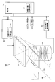
- FIG. 1 is a schematic block diagram of an X-ray inspection apparatus 100 according to the first embodiment.
- the X-ray inspection apparatus 100 includes an X-ray source 10 that outputs an X-ray 18, an X-ray detector 23, and an image acquisition control mechanism 30. Furthermore, the X-ray inspection apparatus 100 includes an input unit 40, an output unit 50, an X-ray source control mechanism 60, an arithmetic unit 70, and a memory 90.
- An inspection object 1 is disposed between the X-ray source 10 and the X-ray detector 23.
- the inspection target 1 is a circuit board on which components are mounted.
- the X-ray source 10, the inspection object 1, and the X-ray detector 23 are installed in order from the bottom, but from the viewpoint of the maintainability of the X-ray source, the X-ray detector 23, These may be arranged in line with the inspection object 1 and the X-ray source 10.
- the X-ray source 10 is controlled by the X-ray source control mechanism 60 to irradiate the inspection object 1 with X-rays 18.
- the inspection target 1 is a substrate on which circuit components are mounted.
- the inspection target 1 is moved by the inspection target drive mechanism 20 (not shown in FIG. 1).
- the inspection target drive mechanism 20 for example, an XY stage or a pair of rails sandwiching the inspection target 1 can be used.
- the X-ray detector 23 is a two-dimensional X-ray detector that detects and images X-rays output from the X-ray source 10 and transmitted through the inspection target 1. That is, the X-ray detector 23 outputs an image represented by the detected X-ray.
- I.I. I. A tube (Image Intensifier) or an FPD (flat panel detector) can be used. From the viewpoint of installation space, it is desirable to use an FPD as the X-ray detector 23. Further, it is desirable that the X-ray detector 23 have high sensitivity so that it can be used in in-line inspection, and it is particularly desirable that the X-ray detector 23 be a direct conversion FPD using CdTe.
- the image acquisition control mechanism 30 includes an image data acquisition unit 34.
- the image data acquisition unit 34 acquires the image data of the X-ray detector 23 specified by the calculation unit 70.
- the input unit 40 is an operation input device for receiving an instruction input from a user.
- the output unit 50 is a device that outputs measurement results and the like to the outside.
- the output unit 50 is a display for displaying an X-ray image or the like configured by the calculation unit 70.
- the user can execute various inputs via the input unit 40, and various calculation results obtained by the processing of the calculation unit 70 are displayed on the output unit 50.
- the image displayed on the output unit 50 may be output for determination of the quality of visual inspection by the user, or may be output as a result of quality determination of the quality determination unit 78 described later.
- the X-ray source control mechanism 60 includes an electron beam control unit 62 that controls the output of the electron beam.
- the electron beam control unit 62 receives designation of the X-ray focal position and the X-ray energy (tube voltage, tube current) from the computing unit 70.
- the designated X-ray energy differs depending on the configuration of the examination object.
- the arithmetic unit 70 executes the program 96 stored in the memory 90 to control each unit, and performs predetermined arithmetic processing.
- the calculation unit 70 includes an X-ray source control unit 72, an image acquisition control unit 74, a reconstruction unit 76, a quality determination unit 78, an inspection target position control unit 80, an X-ray focal position calculation unit 82, and imaging. And a condition setting unit 84.
- the X-ray source control unit 72 determines the X-ray focal position, the X-ray energy, and sends a command to the X-ray source control mechanism 60.
- the image acquisition control unit 74 sends an instruction to the image acquisition control mechanism 30 so that the X-ray detector 23 acquires an image. Further, the image acquisition control unit 74 acquires image data from the image acquisition control mechanism 30.
- the reconstruction unit 76 reconstructs three-dimensional data from the plurality of image data acquired by the image acquisition control unit 74.
- the quality determination unit 78 determines the quality of the inspection target based on the three-dimensional data reconstructed by the reconstruction unit 76 or the fluoroscopic data. For example, the quality determination unit 78 recognizes the shape of the solder ball, and performs the quality determination by determining whether the recognized shape is within a predetermined allowable range. Since the algorithm for performing the quality determination or the input information to the algorithm differs depending on the inspection target, the quality determination unit 78 obtains these from the imaging condition information 94.
- the inspection target position control unit 80 controls the inspection target drive mechanism 20.
- the X-ray focal position calculation unit 82 inspects a certain inspection area of the inspection object 1
- the X-ray focal position calculation unit 82 calculates an X-ray focal position, an irradiation angle and the like with respect to the inspection area.
- the imaging condition setting unit 84 sets conditions (for example, voltage applied to the X-ray source, imaging time, and the like) when the X-ray source 10 outputs X-rays according to the inspection target 1.
- the memory 90 includes X-ray focal position information 92, imaging condition information 94, a program 96 for realizing each function executed by the arithmetic unit 70 described above, and image data 98 imaged by the X-ray detector 23. Including.
- the X-ray focal position information 92 includes the X-ray focal position calculated by the X-ray focal position calculation unit 82.
- the imaging condition information 94 includes information regarding an imaging condition set by the imaging condition setting unit 84 and an algorithm for determining the quality.
- the memory 90 should just be a thing which can accumulate data.
- the memory 90 is configured by, for example, a storage device such as a random access memory (RAM), an electrically erasable and programmable read-only memory (EEPROM), or a hard disc drive (HDD).
- RAM random access memory
- EEPROM electrically erasable and programmable read-only memory
- HDD hard disc drive
- FIG. 2 is a diagram for explaining the configuration of the X-ray inspection apparatus 100 according to the first embodiment.
- FIG. 2 the same parts as in FIG. 1 are given the same reference numerals. Further, in FIG. 2, among the portions shown in FIG. 1, portions directly related to the control of the X-ray focal position, the control of the X-ray detector position, the control of the inspection target position, etc. doing.
- the X-ray source 10 is a scanning X-ray source capable of extending the position (X-ray focal position) for generating X-rays in one direction.
- the X-ray source 10 is a computing unit 70 passing through the X-ray source control mechanism 60. X-rays are generated according to the instruction from.
- FIG. 3 is a cross-sectional view of the X-ray source 10.
- an electron beam 16 is emitted from an electron gun 19 controlled by an electron beam control unit 62 to a target 11 such as tungsten. Then, an X-ray 18 is generated and emitted (outputted) from the position (X-ray focal position 17) where the electron beam 16 collides with the target.
- the X-ray source 10 is a transmissive X-ray source that outputs X-rays in the transmission direction of the electron beam.
- the electron beam system is housed in a vacuum vessel 9.
- the inside of the vacuum vessel 9 is kept vacuum by a vacuum pump 15, and an electron beam 16 accelerated by a high voltage power source 14 is emitted from an electron gun 19.
- the X-ray source 10 can be changed in position where the electron beam 16 collides with the target 11 by deflecting the electron beam 16 by the deflection yoke 12 after being converged by the electron beam focusing coil 13.
- the electron beam 16a deflected by the deflection yoke 12 strikes the target 11, and an X-ray 18a is output from the X-ray focal position 17a.
- the electron beam 16b deflected by the deflection yoke 12 collides with the target 11, and an X-ray 18b is output from the X-ray focal position 17b.
- the target 11 may be a linear target or a continuous surface target.
- the X-ray source 10 can freely set the X-ray focal position 17 within the range of the target.
- the X-ray focal position 17 may be limited to one direction.
- the X-ray source 10 shown in FIG. 3 is a transmission type, the X-ray source 10 may be a reflection type.
- a scanning X-ray source In order to move the X-ray focal position, for example, it is also possible to mechanically move the position of the X-ray source itself each time. However, if a scanning X-ray source is used, it is not necessary to move the X-ray source 10 mechanically within a certain range when moving the X-ray focal point position, for maintainability and reliability. An excellent X-ray inspection apparatus can be realized. In addition, X-ray scanning with a scanning X-ray source requires about 100 times shorter than mechanical scanning (scanning time with a radiation source is several ms, and mechanical movement is several hundred ms). ). Therefore, in the present embodiment, a scanning X-ray source is used. As the X-ray source, other types of radiation sources capable of instantaneously changing the X-ray generation position on the X-ray radiation surface, for example, a multifocal X-ray source may be used.
- the inspection target drive mechanism 20 includes an actuator and a mechanism for fixing the inspection target.
- the inspection object drive mechanism 20 controls the inspection object position drive mechanism controlled by the inspection object position control unit 80 in the arithmetic unit 70, and the visual field of the inspection object independently of the X-ray detector 23.1 or 23.2. Can be moved in the XY directions.
- the inspection target drive mechanism 20 basically moves the inspection target 1 in the Y direction. That is, the inspection target drive mechanism 20 moves the inspection target 1 which has not been inspected from the -Y (or + Y may be) direction to the + Y direction and carries it to the X-ray irradiation range. In addition, the inspection target drive mechanism 20 further moves the inspection target 1 whose inspection has been completed in the + Y direction.
- the inspection target drive mechanism 20 it is preferable to use an apparatus that does not interfere with X-rays as the inspection target drive mechanism 20.
- the inspection target drive mechanism 20 the rails 25a and the rails 25b sandwiching the inspection target 1 from both ends thereof are used.
- the calculation unit 70 sends an instruction to the detector drive control unit 32, the image data acquisition unit 34, and the scanning X-ray source control mechanism 60, and executes the program shown in the flowchart for the inspection process as described later.
- the calculation unit 70 performs acquisition of an X-ray fluoroscopic image and transfer of imaging data at a timing instructed by an instruction through the detector drive control unit 32.
- the arithmetic unit 70 can control the operation of the inspection apparatus according to the input from the input unit 40, and can output the state of each unit or the inspection result from the output unit 50.
- Imaging method From here, the imaging method of the X-ray fluoroscopic image using the X-ray inspection apparatus 100 is demonstrated.
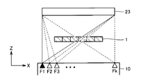
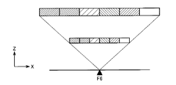
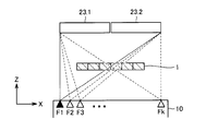
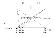
- FIG. 4 is a front view of the X-ray detector 23, the inspection target 1, and the X-ray focal position 17 as viewed from the Y direction.
- FIG. 5 is a top view of the X-ray detector 23, the inspection target 1, and the X-ray focal position 17 as viewed from the Z direction.
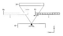
- FIG. 6 is a side view of the X-ray detector 23, the inspection target 1, and the X-ray focal position 17 as viewed from the X direction.
- the X-ray detector 23 shows the position of the X-ray detector 23.
- the sensing area (light receiving unit) of the X-ray detector 23 relates to X-ray detection
- the X-ray detector 23 shown in each drawing may be considered as a light receiving unit.
- the X-ray detector 23 has a square or a light receiving unit with an aspect ratio close thereto.
- the X-ray detector 23 has a size such that transmission images from necessary angles can be acquired at both ends in the X direction of the region to be inspected.
- the entire surface of the inspection object 1 is the inspection object area.
- the X-direction length of the X-ray detector 23 needs to be longer than the X-direction length of the inspection object 1.
- X-ray source 10 has an X-ray radiation area capable of irradiating both ends in the X direction of the examination area from a required angle without moving the examination area in the X direction. .
- the X-ray source 10 sequentially emits X-rays in the Z direction at a plurality of different focal positions (F1 to Fk in the figure) on the line in the X direction.
- the X-ray detector 23 acquires a transmission image for each irradiation.
- X-ray inspection apparatus 100 irradiates and picks up X-rays at focal positions F1 to Fk, respectively, and then moves inspection object 1 from position P1 to P2 in the Y direction, and F1 Perform Fk irradiation and imaging. Similarly, the X-ray inspection apparatus 100 repeats X-ray irradiation and movement of the inspection object 1.
- the irradiation and imaging of the inspection target 1 are completed at the position Pe in FIG. 6, the CT imaging is completed.
- the inspection target 1 is at the position Pe, it enters the X-ray detector 23 that has passed through the lower end of the inspection target area in the Y direction.
- the X-ray inspection apparatus 100 divides the inspection target area into a plurality of areas (partial areas) to manage the captured image. That is, the X-ray inspection apparatus 100 acquires an image (referred to as a partial image) corresponding to each partial region in the captured image, and reconstructs three-dimensional data of the partial region from the partial image. This will be described below.
- FIG. 7 is a perspective view of the inspection object 1.
- the inspection target 1 is divided in the X direction and the Y direction.
- the inspection object 1 is imaged from six directions, that is, 36 directions in each of the X and Y directions.
- the Y direction is divided at a length equal to the division in the X direction.
- the inspection target 1 is divided into six in the X direction and ten in the Y direction.
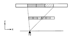
- FIG. 8 is a diagram for describing X-rays transmitted through a partial region.
- the configuration is viewed from the XZ plane.
- the X-ray inspection apparatus 100 performs imaging at the focal points F1 to F11, and acquires an X-ray transmission image for each focal point.
- the X-ray from the focal position F1 is incident on the left end partial region of the inspection object 1 and is incident on the X-ray detector 23.
- the dotted line from the focal position F1 indicates the X-ray emitted at the maximum angle in the right direction.
- X-rays are also output in the left direction from the focal position F1, these X-rays are not shown in FIG.
- the X-ray detector 23 can acquire transmission images of the partial region at the left end and the partial region next to it.
- transmission images can be acquired for one or more partial regions.
- the X-rays emitted from the focal positions F1 to F6 are transmitted to the left end partial region of the inspection object 1, and the transmitted X-rays enter the X-ray detector 23.
- the X-rays emitted from the focal positions F6 to F11 are transmitted to the partial region at the right end of the inspection object 1, and the transmitted X-rays enter the X-ray detector 23.
- X-rays emitted from the six focal positions are transmitted to any partial region, and the transmitted X-rays enter the X-ray detector 23. Therefore, in the imaging in F1 to F11, imaging from six directions is completed for six fields of view.
- the distance interval of the X direction which radiates X-ray the same distance as the division
- the distance interval is not limited to this.
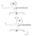
- 9 to 11 show partial images obtained for the focal positions F1, F3 and F6, respectively.
- X-ray inspection apparatus 100 obtains a partial image of the left partial region.
- the partial area of the inspection object 1 and the position on the X-ray detector 23 where the partial area is shown are indicated by the same hatching.
- the image acquisition control unit 74 outputs the focal position F1 based on the focal position, the position of the inspection object 1, the size of the partial area, and the position of the X-ray detector 23, and transmits the left partial area A region in the X-ray detector 23 on which the X-rays enter is determined.
- the image acquisition control unit 74 sends a command to the image acquisition control mechanism 30 so as to acquire an image of the area obtained by the X-ray detector 23.
- the image acquisition control unit 74 stores the acquired image as a partial image in the memory 90.
- the image acquisition control unit 74 may extract an image within the determined area as a partial image from the image of the entire detection surface acquired by the X-ray detector 23.
- X-ray inspection apparatus 100 obtains partial images of three partial regions.
- X-ray inspection apparatus 100 obtains partial images of six partial regions.
- the X-ray inspection apparatus 100 captures X-ray fluoroscopic images from different Y positions by moving the inspection target 1 in the Y direction.
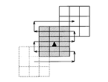
- the movement of the inspection object 1 will be described with reference to FIG. FIG. 12 shows the movement of the partial area 2 of FIG. 7 (the partial area at the left end of FIG. 8).
- the positional relationship in the Y direction between the partial region 2 and the focal position (in FIG. 12, particularly, F11 is shown) changes, and the X-ray output from the focal position F11 The incident angle to the partial area 2 of In this case, since the position of partial region 2 is moved five times from position P1 to position P6, an X-ray fluoroscopic image from six directions in the Y direction is captured.
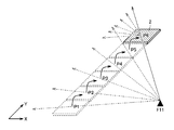
- FIG. 13 is a view showing the incident direction of X-rays incident on the partial region 2.
- the imaging at the position P5 is subsequent to the partial area 2, and the imaging at the position P4 is subsequent to the two subsequent lines.
- the row of is also in the state where imaging is being performed simultaneously. Therefore, the movement in the Y direction and the F1 to F11 irradiation are repeated, and when the last line in the Y direction of the inspection target area has been imaged at the position P6, the imaging for CT examination is completed in the entire area.
- the tip position of the partial region 2 at this time is the position Pe of FIG.
- the X-ray source 10 outputs from the X-ray focal position 17, and the inspection target area of the inspection object 1 is divided in the X direction (first direction).
- a partial image of each of the plurality of partial regions 2 is acquired from the detection result of the X-ray transmitted through each of the plurality of partial regions 2.
- the object 1 is moved in the Y direction (second direction), and the object 1 is moved in the Y direction. While scanning ten X-ray focal positions 17 in the X direction, partial images at each X-ray focal position 17 are sequentially acquired.
- the X-ray inspection apparatus 100 realizes a plurality of irradiation angles in the X direction by focus scanning and a plurality of irradiation angles in the Y direction by mechanical movement of the inspection object.
- the inspection object may be moved only in one direction (the Y direction in the above description). Therefore, compared with the conventional method, the number of movements of the inspection object can be reduced. Therefore, according to the X-ray inspection apparatus 100, highly accurate three-dimensional data can be reconstructed at high speed for the entire inspection object.
- the number of machine operation axes may be one, and the configuration is simple.
- the movement distance of the inspection object 1 in the Y direction for each step and the width of each partial area set in the inspection object 1 are made to coincide with each other. If it is stored, the movement and imaging are repeated, and when imaging for CT examination is completed in the entire area, the inside of the computer storing the imaging data is “imaged from the n ⁇ n direction of the entire surface of the substrate to be inspected. It is possible to make the data gathered. After that, it is possible to arbitrarily select whether to reconstruct the imaging data in a small divided range, to reconstruct it all over at once, or to reconstruct only the region of interest.
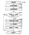
- FIG. 14 is a diagram showing the flow of the entire X-ray examination according to the first embodiment in the form of a flowchart. The flow of the entire X-ray examination according to the first embodiment will be described with reference to FIG.
- X-ray inspection apparatus 100 moves the region to be inspected to a position where it can be imaged, and performs imaging of a fluoroscopic image (step S1402).
- an optical camera (not shown) is mounted to specify the position of the inspection object 1, and it is possible to determine the inspection object area based on the image of the optical camera.
- the X-ray inspection apparatus 100 may automatically determine the inspection target area based on the CAD data of the inspection target 1, or the operator may visually determine it.
- the X-ray examination apparatus 100 examines the fluoroscopic image, and based on the acquired fluoroscopic image, determines the quality of the visual field of the examination object 1 (the range imaged in the fluoroscopic image) (step S1404).
- Various quality evaluation methods have been proposed, and the details are not described here because they are known. For example, as the most basic inspection, a fluoroscopic image is binarized with a fixed value, compared with design information such as CAD data, and it is determined by area whether or not there is a part at a predetermined position on the fluoroscopic image.
- the X-ray inspection apparatus 100 determines whether an inspection by the reconstructed data image is necessary (step S1406).
- the reference of judgment can be set in advance based on design information such as CAD data, or can be judged from the result of pass / fail judgment of the fluoroscopic image. For example, when the component is mounted on only one side in the inspection of the mounting substrate, it may be possible to determine the quality based on the fluoroscopic image, and in some cases it may not be necessary to perform the quality determination based on the reconstructed image.
- step S1406 If the examination based on the reconstruction data is not necessary (NO in step S1406), the X-ray examination apparatus 100 ends the examination (step S1414).
- step S1406 when the examination by the reconstructed image is necessary (YES in step S1406), the X-ray examination apparatus 100 subsequently performs CT imaging on the examination target area (step S1408).
- CT imaging the X-ray inspection apparatus 100 images an inspection target area from a plurality of directions. Details of step S1408 will be described later.
- the X-ray inspection apparatus 100 generates reconstruction data from captured images in a plurality of directions (step S1410).
- Various methods have been proposed for the reconstruction process, and for example, the Feldkamp method can be used.
- the X-ray inspection apparatus 100 performs quality determination based on the reconstruction data (step S1410).
- the quality determination method may be a method using three-dimensional data directly or a method using two-dimensional data (tomographic image) or one-dimensional data (profile). Since these quality determination methods are well known, the quality determination method suitable for the inspection item may be used, and the detailed description will not be repeated here.
- One example of the quality determination will be described below.
- the three-dimensional reconstruction data is binarized with a fixed value. From design information such as CAD data, a position of a part (for example, a solder ball of BGA) is specified in the reconstruction data. From the binarized image, the volume of pixels adjacent to a certain position of the part can be calculated to determine the presence or absence of the part.
- X-ray inspection apparatus 100 ends an inspection (Step S1414).
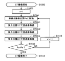
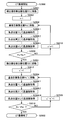
- FIG. 15 is a diagram showing the flow of processing of CT imaging described in FIG. 14 in the form of a flowchart.
- step S1504 the computing unit 70 moves the inspection target 1 to the position Px in order to move the inspection target area to be inspected to an appropriate position.
- the encoder is mounted on the inspection target drive mechanism 20, the position of the inspection target 1 may be set using the encoder. Alternatively, these positions may be set using a general-purpose detector (laser displacement meter or the like).
- the calculation unit 70 sets the X-ray focal position 17 to each focal position (F1 to Fk), irradiates X-rays, and acquires a transmission image (steps S1506.1 to S1506.k). .
- the imaging time exposure time of the detector
- the computing unit 70 acquires a partial image corresponding to each partial region in these processes. Further, operation unit 70 transfers the partial image to, for example, memory 90 for the reconstruction process in reconstruction unit 76.
- the inspection target area is divided into partial areas. However, if the inspection target area is about the size of the partial area, it is not necessary to divide the inspection target area. Alternatively, if the X-ray detector is sufficiently large relative to the examination object, it is not necessary to divide the examination object area. However, considering that the large-sized X-ray detector is expensive, it is practical to divide the inspection object into partial areas as in this embodiment and reconstruct three-dimensional data of each partial area. It is.
- the X-ray focal position 17 of the X-ray source 10 is scanned in the first direction (the X direction in the above example), and divided into a plurality of partial areas in the first direction
- the three-dimensional data of the region to be inspected is reconstructed using partial images corresponding to the X-rays output from the X-ray focal positions 17 and transmitted through the partial regions for each of the regions to be inspected.
- the range in which the X-ray detector 23 has to be present along the first direction can be further reduced, and the examination object from multiple directions necessary for CT reconstruction
- the X-ray transmission image of 1 can be acquired faster.
- FIG. 16 is a diagram for explaining the configuration of the X-ray inspection apparatus 200 according to the second embodiment.
- the X-ray inspection apparatus 200 includes an X-ray source 10, X-ray detectors 23.1 and 23.2, an X-ray detector drive unit 22, an image acquisition control mechanism 30, an input unit 40, and an output unit 50. , An X-ray source control mechanism 60, an operation unit 70, and a memory 90.
- the X-ray source control mechanism 60, the computing unit 70, and the memory 90 have the configuration as described with reference to FIG.
- the difference from the first embodiment is that there is an X-ray detector drive unit 22, that the image acquisition control mechanism 30 includes a detector drive control unit 32, and that there are two X-ray detectors. It is.
- the X-ray detector 23.1 and the X-ray detector 23.2 which are about 1/4 the size of the X-ray detector 23 of the first embodiment.
- the X-ray detector 23.1 and the X-ray detector 23.2 are arranged side by side in the X direction.
- the X-ray detector 23.1 and the X-ray detector 23.2 are attached to the X-ray detector drive unit 22.
- the X-ray detector drive unit 22 operates based on an instruction of the detector drive control unit 32, and moves the X-ray detector 23.1 and the X-ray detector 23.2 integrally in the Y direction.
- the size in the Y direction of the detector is smaller than in the first embodiment.
- the X-ray detector drive unit 22 covers the X-ray detector set 22 by integrally moving the set of X-ray detectors in the Y direction.
- Imaging method From here, an imaging method of an X-ray fluoroscopic image using the X-ray inspection apparatus 200 is described.
- FIG. 17 is a front view of the X-ray detectors 23.1, 23.2, the inspection target 1, and the X-ray focal position 17 as viewed from the Y direction.
- FIG. 18 is a top view of the X-ray detectors 23.1, 23.2, the inspection object 1, and the X-ray focal position 17 as viewed from the Z direction.
- FIG. 19 is a side view of the X-ray detectors 23.1, 23.2, the inspection target 1, and the X-ray focal position 17 as viewed from the X direction.
- the X-ray detectors 23.1 and 23.2 in FIGS. 17 to 19 may be considered to be replaced with the light receiving portions of the X-ray detectors 23.1 and 23.2, respectively.
- X-ray detectors 23.1 and 23.2 are close in the X direction.
- the sum of the widths in the X direction is set such that transmission images from necessary angles can be obtained at both ends of the inspection target area in the X direction.
- the entire surface of the inspection object 1 is the inspection object area.
- the sum of the X-direction widths of the X-ray detectors 23.1 and 23.2 needs to be longer than the X-direction length of the inspection object 1.
- the X-ray source 10 sequentially emits X-rays in the Z direction at a plurality of different focal positions (F1 to Fk in the figure) on the line in the X direction.
- the X-ray detectors 23.1 and 23.2 acquire transmission images for each irradiation at the detection position S1 shown in FIG.
- X-ray inspection apparatus 200 irradiates and captures X-rays at focal positions F1 to Fk respectively, and then moves inspection object 1 from position P1 to P2 in the Y direction. , Irradiation and imaging in F1 to Fk. Similarly, the X-ray inspection apparatus 200 repeats X-ray irradiation and movement of the inspection object 1.
- the irradiation and imaging of the inspection target 1 are completed at the position Pe in FIG. 19, the CT imaging at the detection position S1 ends.
- the X-ray inspection apparatus 200 moves the detector position to S2 and the substrate position to P1 ', as shown in the upper drawing of FIG.
- the X-ray inspection apparatus 200 repeats the irradiation with F1 to Fk and the movement of the inspection object in the Y direction until the last line in the Y direction of the inspection object ends imaging in Pe ′.
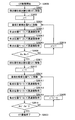
- FIG. 20 is a diagram showing, in a flowchart form, a flow of processing of CT imaging according to the second embodiment.
- step S2000 when CT imaging processing is started (step S2000), operation unit 70 moves X-ray detectors 23.1 and 23.2 to detector position S1 in step S2001. .
- step S2004 the arithmetic unit 70 moves the inspection target 1 to the position Px in order to move the inspection target area to be inspected to an appropriate position.
- the computing unit 70 sets the X-ray focal position 17 to each focal position (F1 to Fk), irradiates X-rays, and acquires a transmission image at the detector position S1 (step S2006.1 Step S2006.k).
- the arithmetic unit 70 obtains partial images corresponding to the respective partial regions.
- operation unit 70 transfers the partial image to, for example, memory 90 for the reconstruction process in reconstruction unit 76.
- step S2008 operation unit 70 moves X-ray detectors 23.1 and 23.2 to detector position S2 in step S2011.
- step S2014 the arithmetic unit 70 moves the inspection target 1 to the position Px 'in order to move the inspection target area to be inspected to an appropriate position.
- the calculation unit 70 sets the X-ray focal position 17 to each focal position (F1 to Fk), irradiates X-rays, and acquires a transmission image at the detector position S2 (step S2016.1 to Step S2016. K).
- the arithmetic unit 70 obtains partial images corresponding to the respective partial regions. Further, operation unit 70 transfers the partial image to, for example, memory 90 for the reconstruction process in reconstruction unit 76.
- step S2018 operation unit 70 ends the CT imaging process (step S2022).
- the X-ray inspection apparatus 200 moves the detector position two or more times depending on the size of the detector in the Y direction and the number of imaging required. , May be imaged.
- Third Embodiment As a third embodiment, an X-ray detection apparatus provided with a scanning X-ray source that scans X-rays on two lines will be described.
- the configuration of the X-ray detection apparatus according to the third embodiment is the same as that of the second embodiment except for the X-ray source 10. Therefore, the description of the configuration will not be repeated.
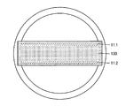
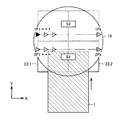
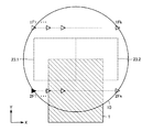
- FIG. 21 is a cross-sectional view of the X-ray source 10 according to the third embodiment.
- FIG. 22 is a top view of the X-ray source 10 according to the third embodiment.
- This X-ray source 10 differs from that of the first embodiment in that it comprises two opposed linear targets 11.1 and 11.2.
- the other main components are the same as those of the first embodiment, and the description thereof will not be repeated.
- targets 11.1 and 11.2 are reflective targets arranged such that X-rays 18 traveling in the reflection direction of electron beam 16 are output to the outside. That is, the X-ray source 10 is a reflective X-ray source. By using a reflective target as a target, the X-ray source 10 can output high-intensity X-rays as compared to a transmissive X-ray source. This contributes to shortening of imaging time and high image quality.
- vacuum window 130 of X-ray source 10 is arranged to cover targets 11.1 and 11.2.
- the vacuum window 130 is made of a material that transmits X-rays, such as beryllium.
- the shape of the vacuum window 130 is not limited to that shown in FIG. 22 and may be installed in a range in which X-rays in the direction necessary for CT imaging travel.
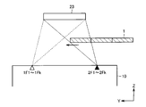
- FIG. 23 is a front view of the X-ray detectors 23.1, 23.2, the inspection target 1, and the X-ray focal position 17 as viewed from the Y direction.
- FIG. 24 is a top view of the X-ray detectors 23.1, 23.2, the inspection target 1, and the X-ray focal position 17 as viewed from the Z direction.
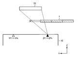
- FIG. 25 is a side view of the X-ray detectors 23.1, 23.2, the inspection target 1, and the X-ray focal position 17 as viewed from the X direction.
- X-ray detectors 23.1 and 23.2 are close in the X direction.
- the sum of the widths in the X direction is set such that transmission images from necessary angles can be obtained at both ends of the inspection target area in the X direction.
- the entire surface of the inspection object 1 is the inspection object area.
- the sum of the X-direction widths of the X-ray detectors 23.1 and 23.2 needs to be longer than the X-direction length of the inspection object 1.
- the X-ray source 10 sequentially emits X-rays in the Z direction at a plurality of different focal positions on the line in the X direction.
- the X-ray detectors 23.1 and 23.2 acquire transmission images for each irradiation at the detection position S1 shown in FIG. At this time, the X-ray source 10 emits X-rays at the X-ray focal positions 1F1 to 1Fk.
- the X-ray examination apparatus moves the X-ray detectors 23.1 and 23.2 to the detection position S2.
- the X-ray detectors 23.1 and 23.2 acquire transmission images of X-rays from the focal positions 2F2 to 2Fk.
- the X-ray inspection apparatus irradiates and captures X-rays at focal positions 1F1 to 1Fk respectively, and then moves inspection object 1 from position P1 to P2 in the Y direction. , Irradiation and imaging at 1F1 to 1Fk. Similarly, the X-ray inspection apparatus 200 repeats X-ray irradiation and movement of the inspection object 1.
- the CT imaging at the detection position S1 ends.
- the X-ray inspection apparatus moves the detector position to S2 and the substrate position to P1 ', as shown in the upper drawing of FIG.
- the X-ray examination apparatus 200 repeats irradiation with 2F1 to 2Fk and movement of the examination object in the Y direction until imaging is finished at the last line in the Y direction of the examination object at Pe ′.
- the basic irradiation and imaging methods are the same as those in the second embodiment, but at the detector position S1, the X-ray focal points 1F1 to 1Fk are At the position S2, the X-ray focal points 2F1 to 2Fk are used.
- FIG. 26 is a diagram showing, in a flowchart form, a flow of processing of CT imaging according to the third embodiment.
- step S2600 when CT imaging processing is started (step S2600), operation unit 70 moves X-ray detectors 23.1 and 23.2 to detector position S1 in step S2601. .
- step S2604 the operation unit 70 moves the inspection target 1 to the position Px in order to move the inspection target area to be inspected to an appropriate position.
- the calculation unit 70 sets the X-ray focal position 17 to the focal positions 1F1 to 1Fk, irradiates X-rays, and acquires transmission images at the detector position S1 (steps S2606.1 to S2606. k).
- the arithmetic unit 70 obtains partial images corresponding to the respective partial regions.
- operation unit 70 transfers the partial image to, for example, memory 90 for the reconstruction process in reconstruction unit 76.
- step S2608 operation unit 70 moves X-ray detectors 23.1 and 23.2 to detector position S2 in step S2611.
- step S2614 the computing unit 70 moves the inspection target 1 to the position Px 'in order to move the inspection target area to be inspected to an appropriate position.
- the computing unit 70 sets the X-ray focal position 17 to the focal positions 2F1 to 2Fk, irradiates X-rays, and acquires a transmission image at the detector position S2 (steps S2616.1 to S2616. k).
- the arithmetic unit 70 obtains partial images corresponding to the respective partial regions.
- operation unit 70 transfers the partial image to, for example, memory 90 for the reconstruction process in reconstruction unit 76.
- step S2618 operation unit 70 ends the CT imaging process (step S2622).
- the drive of the X-ray detector can be omitted by devising the arrangement of the X-ray detectors 23.1 and 23.2.
- an X-ray inspection apparatus in which the X-ray detector is disposed as described above will be described.
- the configuration of the X-ray detection apparatus according to the fourth embodiment is substantially similar to that of the third embodiment. Therefore, the description of the configuration will not be repeated. However, it differs from the third embodiment in that the arrangement of the X-ray detectors 23.1 and 23.2 is different, and that the X-ray detector drive unit 22 and the detector drive control unit 32 are not provided. .
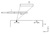
- FIG. 27 is a diagram for explaining the positions of the X-ray detectors 23.1 and 23.2 in the XY plane.
- FIG. 28 is a diagram for describing the positions of X-ray detectors 23.1 and 23.2 in the YZ plane.
- X-ray detectors 23.1 and 23.2 are arranged to be sandwiched between two lines of the X-ray scan in the Y direction.
- the relationship between the X-direction width obtained by combining the X-ray detectors 23.1 and 23.2 and the X-direction width of the inspection object is the same as that in the second embodiment or the third embodiment.
- X-ray detector 23 X-ray detectors 23.1 and 23.2 (hereinafter collectively referred to as X-ray detector 23), inspection object 1 and X-ray source 10 in the YZ plane.
- the positional relationship is similar to that of the third embodiment.
- the X-ray inspection method according to the present embodiment is basically the same as that of the third embodiment. However, in the present inspection method, the order of irradiating X-rays at the focal positions 1F1 to 1Fk and the focal positions 2F1 to 2Fk is different from that of the third embodiment.
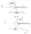
- the X-ray inspection method according to the present embodiment will be described with reference to FIGS. 29 to 31.
- FIGS. 29 to 31 are views for explaining the X-ray inspection method according to the fourth embodiment.
- the inspection object 1 is in a section in which only imaging at focal positions 2F1 to 2Fk (hereinafter referred to as F2 series) is effective.
- the X-ray source does not output X-rays at focal positions 1F1 to 1Fk (hereinafter referred to as F1 series).
- the inspection target 1 moves in the Y direction from the state shown in FIG. 29, and imaging by both the F1 series and the F2 series is effective.
- the X-ray detector 23 moves the inspection object 1 after imaging a predetermined number of sheets at the focal positions of the F1 series and the F2 series.
- the inspection target moves in the Y direction from the state shown in FIG. 30, and only imaging in the F1 series is effective. At this time, the focal position of the F1 series is not used for X-ray irradiation.
Landscapes
- Health & Medical Sciences (AREA)
- Engineering & Computer Science (AREA)
- Nuclear Medicine, Radiotherapy & Molecular Imaging (AREA)
- Pulmonology (AREA)
- Radiology & Medical Imaging (AREA)
- Theoretical Computer Science (AREA)
- Physics & Mathematics (AREA)
- Life Sciences & Earth Sciences (AREA)
- Chemical & Material Sciences (AREA)
- Analytical Chemistry (AREA)
- Biochemistry (AREA)
- General Health & Medical Sciences (AREA)
- General Physics & Mathematics (AREA)
- Immunology (AREA)
- Pathology (AREA)
- Analysing Materials By The Use Of Radiation (AREA)
Abstract
Description
特許文献1に記載の方法では、撮像できる方向および撮像枚数は、検出器エリアの区切り方で決まっていて変えることができない。特許文献1では、各関心領域について、9枚の画像を得る例が示されている。
さらに好ましくは、X線源は、複数のライン上にそれぞれ配置された複数のターゲットを含み、繰り返すステップにおいて、各ターゲット上でX線焦点位置を走査する。
本発明の他の局面に従うと、対象物の検査対象領域の3次元データを再構成するためのX線検査装置を提供する。X線検査装置は、X線を出力するX線源と、X線を検出して検出したX線が示す画像を出力するX線検出部と、X線検査装置の動作を制御する制御部とを含む。制御部は、X線源のX線焦点位置から出力し、検査対象領域を第1の方向について分割した複数の部分領域をそれぞれ透過したX線の検出結果から、複数の部分領域の各々についての部分画像を取得するための画像取得部と、X線源にX線焦点位置を第1の方向に走査させるためのX線源制御部と、X線源制御部によるX線焦点位置の走査に伴って、複数のX線焦点位置の各々において画像取得部が取得した部分画像から、3次元データを再構成するための再構成部とを含む。
(構成の概略)
図1を参照して、第1の実施の形態に係るX線検査装置100の構成について説明する。図1は、第1の実施の形態に係るX線検査装置100の概略ブロック図である。
X線焦点位置計算部82は、検査対象1のある検査エリアを検査する際に、その検査エリアに対するX線焦点位置や照射角などを計算する。
第1の実施の形態に係るX線検査装置100の具体的構成について、図2を参照して説明する。図2は、第1の実施の形態に係るX線検査装置100の構成を説明するための図である。なお、図2において、図1と同一部分には、同一符号を付している。また、図2では、図1に示した部分のうち、X線焦点位置の制御、X線検出器位置の制御、検査対象位置の制御等に直接関係し、説明に必要な部分を抜き出して記載している。
からの命令に従って、X線を発生させる。
ここからは、X線検査装置100を用いたX線透視画像の撮像方式について説明する。
図14は、第1の実施の形態に係るX線検査全体の流れをフローチャート形式で示す図である。図14を参照して、第1の実施の形態に係るX線検査全体の流れについて説明する。
以上の説明では、検査対象領域が部分領域に分割されているとしたが、検査対象領域が部分領域程度の大きさであれば、検査対象領域を分割する必要はない。あるいは、X線検出器が検査対象に対し十分大きければ、検査対象領域を分割する必要はない。ただし、大きなサイズのX線検出器は高価であることを考えると、本実施の形態のように検査対象を部分領域に分割し、各部分領域の3次元データを再構成する手法が、実用的である。
(構成)
第2の実施の形態に係るX線検査装置200の構成について図16を参照して説明する。図16は、第2の実施の形態に係るX線検査装置200の構成を説明するための図である。
ここからは、X線検査装置200を用いたX線透視画像の撮像方式について説明する。
第2の実施の形態に係るX線検査方法の大きな流れは、第1の実施の形態と同様であり、繰り返さない。ただし、CT撮像処理が第1の実施の形態と異なる。第2の実施の形態に係るCT撮像の詳細について、図20を参照して説明する。図20は、第2の実施の形態に係るCT撮像の処理の流れをフローチャート形式で示す図である。
以上では、検出器位置を1回移動する例を説明したが、Y方向の検出器サイズおよび必要とされる撮像枚数によっては、X線検査装置200は、検出器位置を2回以上移動して、撮像してもよい。
第3の実施の形態として、2ライン上でX線を走査する走査型X線源を備えるX線検出装置について説明する。なお、第3の実施の形態に係るX線検出装置の構成は、X線源10を除いて、第2の実施の形態と同様であるものとする。そのため、その構成の説明は繰り返さない。
第3の実施の形態において、X線検出器23.1および23.2の配置を工夫することで、X線検出器の駆動を省略することができる。第4の実施の形態として、このようにX線検出器が配置されているX線検査装置について説明する。
本実施の形態に係るX線検査方式は、基本的には、第3の実施の形態のものと同様である。しかしながら、本検査方式では、焦点位置1F1~1Fkと、焦点位置2F1~2FkでX線を照射する順序が、第3の実施の形態と異なる。本実施の形態に係るX線検査方式について、図29~図31を参照して説明する。図29~図31は、各々、第4の実施の形態に係るX線検査方式について説明するための図である。
図29では、検査対象1は、焦点位置2F1~2Fk(以下、F2シリーズとよぶ)での撮像のみが有効な区間にある。このとき、X線源は、焦点位置1F1~1Fk(以下、F1シリーズとよぶ)では、X線を出力しない。
上記の各実施の形態を適宜組み合わせたものも、本発明の範囲に含まれることはもちろんである。例えば、第3の実施の形態および第4の実施の形態においても、第1の実施の形態のように、複数のX線検出器のかわりに、大型の1枚のX線検出器を用いてもよい。
Claims (7)
- X線源(10)が出力して、対象物(1)の検査対象領域を透過したX線をX線検出部で検出し、検出されたX線が示す画像から前記検査対象領域の3次元データを再構成するX線検査方法であって、
前記X線源がX線焦点位置(17)から出力し、前記検査対象領域を第1の方向について分割した複数の部分領域をそれぞれ透過したX線の検出結果から、前記複数の部分領域の各々についての部分画像を取得するステップ(S1506)と、
前記X線源のX線焦点位置を前記第1の方向に走査しつつ、前記部分画像を取得するステップを繰り返すステップ(S1504,S1508,S1510)と、
前記X線焦点位置の走査によって取得された、複数の前記X線焦点位置の各々における部分画像から、前記3次元データを再構成するステップ(S1410)とを備える、X線検査方法。 - 前記検査対象領域は、前記第1の方向および前記第1の方向に交わる第2の方向について複数の前記部分領域に分割されており、
前記繰り返すステップは、前記X線源のX線焦点位置を前記第1の方向に走査した後に、前記対象物を前記第2の方向に移動させ、前記対象物を前記第2の方向に移動した状態から前記X線源のX線焦点位置を前記第1の方向に走査しつつ、前記部分画像を取得するステップを繰り返すステップを含む、請求の範囲第1項に記載のX線検査方法。 - 前記繰り返すステップにおいて、複数のライン上で前記X線焦点位置を走査する、請求の範囲第1項に記載のX線検査方法。
- 前記X線源は、複数の前記ライン上にそれぞれ配置された複数のターゲットを含み、
前記繰り返すステップにおいて、各前記ターゲット上で前記X線焦点位置を走査する、請求の範囲第3項に記載のX線検査方法。 - 前記X線検出部は、前記ラインに交わる方向について、2つの前記ターゲットに挟まれるように配置される、請求の範囲第4項に記載のX線検査方法。
- 各前記ターゲットは、反射型ターゲットである、請求の範囲第4項に記載のX線検査方法。
- 対象物(1)の検査対象領域の3次元データを再構成するためのX線検査装置(100)であって、
X線を出力するX線源(10)と、
前記X線を検出して検出したX線が示す画像を出力するX線検出部(23)と、
前記X線検査装置の動作を制御する制御部(70)とを備え、
前記制御部は、
前記X線源のX線焦点位置(17)から出力し、前記検査対象領域を第1の方向について分割した複数の部分領域をそれぞれ透過したX線の検出結果から、前記複数の部分領域の各々についての部分画像を取得するための画像取得部(74)と、
前記X線源に前記X線焦点位置を前記第1の方向に走査させるためのX線源制御部(72)と、
前記X線源制御部による前記X線焦点位置の走査に伴って、複数の前記X線焦点位置の各々において前記画像取得部が取得した前記部分画像から、前記3次元データを再構成するための再構成部(76)とを含む、X線検査装置。
Priority Applications (4)
| Application Number | Priority Date | Filing Date | Title |
|---|---|---|---|
| CN200980152060.2A CN102265142A (zh) | 2008-12-22 | 2009-12-21 | X射线检查方法和x射线检查装置 |
| JP2010544055A JP5177236B2 (ja) | 2008-12-22 | 2009-12-21 | X線検査方法およびx線検査装置 |
| EP09834832.9A EP2378280A4 (en) | 2008-12-22 | 2009-12-21 | X-RAY INSPECTION METHOD AND X-RAY INSPECTION APPARATUS |
| US13/140,971 US20110249795A1 (en) | 2008-12-22 | 2009-12-21 | X-ray inspection method and x-ray inspection apparatus |
Applications Claiming Priority (2)
| Application Number | Priority Date | Filing Date | Title |
|---|---|---|---|
| JP2008326252 | 2008-12-22 | ||
| JP2008-326252 | 2008-12-22 |
Publications (1)
| Publication Number | Publication Date |
|---|---|
| WO2010074031A1 true WO2010074031A1 (ja) | 2010-07-01 |
Family
ID=42287640
Family Applications (1)
| Application Number | Title | Priority Date | Filing Date |
|---|---|---|---|
| PCT/JP2009/071244 Ceased WO2010074031A1 (ja) | 2008-12-22 | 2009-12-21 | X線検査方法およびx線検査装置 |
Country Status (5)
| Country | Link |
|---|---|
| US (1) | US20110249795A1 (ja) |
| EP (1) | EP2378280A4 (ja) |
| JP (1) | JP5177236B2 (ja) |
| CN (1) | CN102265142A (ja) |
| WO (1) | WO2010074031A1 (ja) |
Cited By (1)
| Publication number | Priority date | Publication date | Assignee | Title |
|---|---|---|---|---|
| WO2015099104A1 (ja) * | 2013-12-27 | 2015-07-02 | 大王製紙株式会社 | 吸収性物品の体液吸収形態の表示・解析方法 |
Families Citing this family (6)
| Publication number | Priority date | Publication date | Assignee | Title |
|---|---|---|---|---|
| JP5863547B2 (ja) * | 2012-04-20 | 2016-02-16 | ヤマハ発動機株式会社 | プリント基板の検査装置 |
| JP6241758B2 (ja) * | 2015-06-15 | 2017-12-06 | 国立大学法人鳥取大学 | 吸収性物品の体液吸収形態の表示・解析方法 |
| US11009471B2 (en) | 2018-09-12 | 2021-05-18 | Illinois Tool Works Inc. | Dynamic radiation collimation for non destructive analysis of test objects |
| CN111352170B (zh) * | 2020-03-09 | 2021-03-23 | 浙江云特森科技有限公司 | 一种分段式扫描方法 |
| CN114160966A (zh) * | 2021-12-28 | 2022-03-11 | 镭射谷科技(深圳)股份有限公司 | 激光加工装置 |
| WO2025098589A1 (en) * | 2023-11-06 | 2025-05-15 | Carl Zeiss Smt Gmbh | X-ray inspection system for inspection of an object |
Citations (19)
| Publication number | Priority date | Publication date | Assignee | Title |
|---|---|---|---|---|
| JPS5423492A (en) * | 1977-07-25 | 1979-02-22 | Jeol Ltd | X-ray generator |
| JPS5425190A (en) * | 1977-07-28 | 1979-02-24 | Yoshinori Hayakawa | Desired section transmission computer tomography |
| JPS56136529A (en) * | 1980-03-28 | 1981-10-24 | Tokyo Shibaura Electric Co | Apparatus for reconstituting image |
| JPS5994349A (ja) * | 1982-11-19 | 1984-05-31 | Toshiba Corp | 帯状陽極x線管 |
| JPS614139A (ja) * | 1984-06-18 | 1986-01-10 | Canon Inc | X線発生装置 |
| JPS61155845A (ja) * | 1984-12-28 | 1986-07-15 | Toshiba Corp | 断層撮影装置 |
| JPH0377008A (ja) * | 1989-08-21 | 1991-04-02 | Hitachi Ltd | X線透過画像信号検出装置並びにx線透過画像によるはんだ付検査方式 |
| JP2001076656A (ja) * | 1999-09-09 | 2001-03-23 | Hitachi Medical Corp | X線管 |
| JP2001351551A (ja) * | 2000-06-06 | 2001-12-21 | Kazuo Taniguchi | X線管 |
| US6628745B1 (en) * | 2000-07-01 | 2003-09-30 | Martin Annis | Imaging with digital tomography and a rapidly moving x-ray source |
| JP2004108990A (ja) * | 2002-09-19 | 2004-04-08 | Toshiba It & Control Systems Corp | フィルタ処理付ラミノグラフ |
| JP2005080750A (ja) * | 2003-09-05 | 2005-03-31 | Ge Medical Systems Global Technology Co Llc | X線ct装置およびx線管 |
| JP2005135693A (ja) * | 2003-10-29 | 2005-05-26 | Ishikawajima Harima Heavy Ind Co Ltd | X線装置 |
| JP2005321282A (ja) * | 2004-05-07 | 2005-11-17 | Hamamatsu Photonics Kk | X線検査装置 |
| JP2006177760A (ja) | 2004-12-22 | 2006-07-06 | Nagoya Electric Works Co Ltd | X線検査装置、x線検査方法およびx線検査プログラム |
| JP2006322799A (ja) * | 2005-05-18 | 2006-11-30 | Shimadzu Corp | X線撮影装置 |
| WO2007051587A2 (de) * | 2005-11-07 | 2007-05-10 | Comet Gmbh | Vorrichtung zur röntgen-tomosynthese |
| JP2007127668A (ja) | 2000-12-06 | 2007-05-24 | Teradyne Inc | 偏心断層合成 |
| JP2009080055A (ja) * | 2007-09-27 | 2009-04-16 | Hitachi Ltd | 放射線非破壊検査システム及び配管の検査方法 |
Family Cites Families (9)
| Publication number | Priority date | Publication date | Assignee | Title |
|---|---|---|---|---|
| JP3174621B2 (ja) * | 1992-05-28 | 2001-06-11 | 株式会社日立製作所 | 産業用ct装置とそのスキャノグラム撮影方法 |
| JPH10211196A (ja) * | 1997-01-31 | 1998-08-11 | Olympus Optical Co Ltd | X線ctスキャナ装置 |
| US6324249B1 (en) * | 2001-03-21 | 2001-11-27 | Agilent Technologies, Inc. | Electronic planar laminography system and method |
| US7106830B2 (en) * | 2002-06-12 | 2006-09-12 | Agilent Technologies, Inc. | 3D x-ray system adapted for high speed scanning of large articles |
| JP2004219224A (ja) * | 2003-01-14 | 2004-08-05 | Toshiba It & Control Systems Corp | コンピュータ断層撮影装置 |
| JP4603823B2 (ja) * | 2003-10-14 | 2010-12-22 | キヤノン株式会社 | 放射線撮像装置、放射線撮像方法及びプログラム |
| US7023950B1 (en) * | 2004-02-11 | 2006-04-04 | Martin Annis | Method and apparatus for determining the position of an x-ray cone beam produced by a scanning electron beam |
| JP4504740B2 (ja) * | 2004-06-10 | 2010-07-14 | 東芝Itコントロールシステム株式会社 | コンピュータ断層撮影装置 |
| US7529336B2 (en) * | 2007-05-31 | 2009-05-05 | Test Research, Inc. | System and method for laminography inspection |
-
2009
- 2009-12-21 WO PCT/JP2009/071244 patent/WO2010074031A1/ja not_active Ceased
- 2009-12-21 CN CN200980152060.2A patent/CN102265142A/zh active Pending
- 2009-12-21 EP EP09834832.9A patent/EP2378280A4/en not_active Withdrawn
- 2009-12-21 JP JP2010544055A patent/JP5177236B2/ja not_active Expired - Fee Related
- 2009-12-21 US US13/140,971 patent/US20110249795A1/en not_active Abandoned
Patent Citations (19)
| Publication number | Priority date | Publication date | Assignee | Title |
|---|---|---|---|---|
| JPS5423492A (en) * | 1977-07-25 | 1979-02-22 | Jeol Ltd | X-ray generator |
| JPS5425190A (en) * | 1977-07-28 | 1979-02-24 | Yoshinori Hayakawa | Desired section transmission computer tomography |
| JPS56136529A (en) * | 1980-03-28 | 1981-10-24 | Tokyo Shibaura Electric Co | Apparatus for reconstituting image |
| JPS5994349A (ja) * | 1982-11-19 | 1984-05-31 | Toshiba Corp | 帯状陽極x線管 |
| JPS614139A (ja) * | 1984-06-18 | 1986-01-10 | Canon Inc | X線発生装置 |
| JPS61155845A (ja) * | 1984-12-28 | 1986-07-15 | Toshiba Corp | 断層撮影装置 |
| JPH0377008A (ja) * | 1989-08-21 | 1991-04-02 | Hitachi Ltd | X線透過画像信号検出装置並びにx線透過画像によるはんだ付検査方式 |
| JP2001076656A (ja) * | 1999-09-09 | 2001-03-23 | Hitachi Medical Corp | X線管 |
| JP2001351551A (ja) * | 2000-06-06 | 2001-12-21 | Kazuo Taniguchi | X線管 |
| US6628745B1 (en) * | 2000-07-01 | 2003-09-30 | Martin Annis | Imaging with digital tomography and a rapidly moving x-ray source |
| JP2007127668A (ja) | 2000-12-06 | 2007-05-24 | Teradyne Inc | 偏心断層合成 |
| JP2004108990A (ja) * | 2002-09-19 | 2004-04-08 | Toshiba It & Control Systems Corp | フィルタ処理付ラミノグラフ |
| JP2005080750A (ja) * | 2003-09-05 | 2005-03-31 | Ge Medical Systems Global Technology Co Llc | X線ct装置およびx線管 |
| JP2005135693A (ja) * | 2003-10-29 | 2005-05-26 | Ishikawajima Harima Heavy Ind Co Ltd | X線装置 |
| JP2005321282A (ja) * | 2004-05-07 | 2005-11-17 | Hamamatsu Photonics Kk | X線検査装置 |
| JP2006177760A (ja) | 2004-12-22 | 2006-07-06 | Nagoya Electric Works Co Ltd | X線検査装置、x線検査方法およびx線検査プログラム |
| JP2006322799A (ja) * | 2005-05-18 | 2006-11-30 | Shimadzu Corp | X線撮影装置 |
| WO2007051587A2 (de) * | 2005-11-07 | 2007-05-10 | Comet Gmbh | Vorrichtung zur röntgen-tomosynthese |
| JP2009080055A (ja) * | 2007-09-27 | 2009-04-16 | Hitachi Ltd | 放射線非破壊検査システム及び配管の検査方法 |
Non-Patent Citations (1)
| Title |
|---|
| See also references of EP2378280A4 |
Cited By (3)
| Publication number | Priority date | Publication date | Assignee | Title |
|---|---|---|---|---|
| WO2015099104A1 (ja) * | 2013-12-27 | 2015-07-02 | 大王製紙株式会社 | 吸収性物品の体液吸収形態の表示・解析方法 |
| CN105849538A (zh) * | 2013-12-27 | 2016-08-10 | 大王制纸株式会社 | 吸收性物品的体液吸收形态的显示和分析方法 |
| US10156529B2 (en) | 2013-12-27 | 2018-12-18 | Daio Paper Corporation | Method for displaying/analyzing body fluid absorption mode of absorbent article |
Also Published As
| Publication number | Publication date |
|---|---|
| CN102265142A (zh) | 2011-11-30 |
| JP5177236B2 (ja) | 2013-04-03 |
| EP2378280A4 (en) | 2013-06-05 |
| JPWO2010074031A1 (ja) | 2012-06-14 |
| US20110249795A1 (en) | 2011-10-13 |
| EP2378280A1 (en) | 2011-10-19 |
Similar Documents
| Publication | Publication Date | Title |
|---|---|---|
| JP5104956B2 (ja) | X線検査装置およびx線検査方法 | |
| JP5104962B2 (ja) | X線検査方法およびx線検査装置 | |
| CN101960296B (zh) | X射线检查装置及x射线检查方法 | |
| JP4551919B2 (ja) | 断層撮影の検査システムおよびその方法 | |
| US7680242B2 (en) | X-ray examination method and X-ray examination apparatus | |
| JP5177236B2 (ja) | X線検査方法およびx線検査装置 | |
| US8693618B2 (en) | Scanner device and method for computed tomography imaging | |
| JPH02501411A (ja) | エレクトロニクスの検査のための自動ラミノグラフシステム | |
| JP5167810B2 (ja) | X線検査装置 | |
| JP7542327B2 (ja) | 検査装置 | |
| JP5263204B2 (ja) | X線検査装置およびx線検査方法 | |
| JP7511819B2 (ja) | 非破壊検査装置の非破壊検査方法 | |
| JP2011191217A (ja) | X線検査方法、x線検査装置およびx線検査プログラム | |
| JP5115574B2 (ja) | X線検査装置およびx線検査方法 | |
| JP5125297B2 (ja) | X線検査装置およびx線検査方法 | |
| JP5167882B2 (ja) | X線検査装置およびx線検査方法 | |
| US12263024B2 (en) | System and method for incorporating lidar-based techniques with a computed tomography system |
Legal Events
| Date | Code | Title | Description |
|---|---|---|---|
| WWE | Wipo information: entry into national phase |
Ref document number: 200980152060.2 Country of ref document: CN |
|
| 121 | Ep: the epo has been informed by wipo that ep was designated in this application |
Ref document number: 09834832 Country of ref document: EP Kind code of ref document: A1 |
|
| ENP | Entry into the national phase |
Ref document number: 2010544055 Country of ref document: JP Kind code of ref document: A |
|
| WWE | Wipo information: entry into national phase |
Ref document number: 13140971 Country of ref document: US |
|
| NENP | Non-entry into the national phase |
Ref country code: DE |
|
| WWE | Wipo information: entry into national phase |
Ref document number: 2009834832 Country of ref document: EP |