WO2010079556A1 - 移動体検出方法および移動体検出装置 - Google Patents
移動体検出方法および移動体検出装置 Download PDFInfo
- Publication number
- WO2010079556A1 WO2010079556A1 PCT/JP2009/006999 JP2009006999W WO2010079556A1 WO 2010079556 A1 WO2010079556 A1 WO 2010079556A1 JP 2009006999 W JP2009006999 W JP 2009006999W WO 2010079556 A1 WO2010079556 A1 WO 2010079556A1
- Authority
- WO
- WIPO (PCT)
- Prior art keywords
- region
- distance
- region division
- geodetic
- inter
- Prior art date
- Legal status (The legal status is an assumption and is not a legal conclusion. Google has not performed a legal analysis and makes no representation as to the accuracy of the status listed.)
- Ceased
Links
Images


Classifications
-
- G—PHYSICS
- G06—COMPUTING OR CALCULATING; COUNTING
- G06T—IMAGE DATA PROCESSING OR GENERATION, IN GENERAL
- G06T7/00—Image analysis
- G06T7/20—Analysis of motion
- G06T7/215—Motion-based segmentation
-
- G—PHYSICS
- G06—COMPUTING OR CALCULATING; COUNTING
- G06T—IMAGE DATA PROCESSING OR GENERATION, IN GENERAL
- G06T2207/00—Indexing scheme for image analysis or image enhancement
- G06T2207/10—Image acquisition modality
- G06T2207/10016—Video; Image sequence
-
- G—PHYSICS
- G06—COMPUTING OR CALCULATING; COUNTING
- G06T—IMAGE DATA PROCESSING OR GENERATION, IN GENERAL
- G06T2207/00—Indexing scheme for image analysis or image enhancement
- G06T2207/30—Subject of image; Context of image processing
- G06T2207/30196—Human being; Person
-
- G—PHYSICS
- G06—COMPUTING OR CALCULATING; COUNTING
- G06T—IMAGE DATA PROCESSING OR GENERATION, IN GENERAL
- G06T2207/00—Indexing scheme for image analysis or image enhancement
- G06T2207/30—Subject of image; Context of image processing
- G06T2207/30241—Trajectory
Definitions
- the present invention relates to an image processing technique for detecting a moving body by extracting a region of the moving body in an image, and in particular, even when the moving body is a target that moves while changing its shape like a person,
- the present invention relates to an apparatus for detecting a region of a moving body based on motion information in an image.
- one mode of the moving object detection method is a method of detecting a moving object in a moving image by dividing all or part of the area of the moving object in the moving image.
- FIGS. 8A and 8B are diagrams for explaining the characteristics of the geodesic distance.
- FIGS. 9A to 9E are diagrams showing examples of clustering using geodetic distances.
- FIGS. 10A to 10F are diagrams showing examples of the geodetic distance matrix, the representative geodetic distance matrix, and the reference matrix.
- FIGS. 11A to 11D are diagrams showing examples of a representative geodetic distance matrix and a reference matrix.
- FIG. 12 is a diagram illustrating an example of an image generated in the image output step.
- FIG. 13 is a flowchart showing an operation procedure of the moving object detection device according to another embodiment of the present invention.
- FIG. 14 is a flowchart showing an operation procedure of the moving object detection device according to the second embodiment of the present invention.
- an image input step for receiving a plurality of pictures constituting a moving picture, and an image between two temporally adjacent pictures for each block composed of one or more pixels constituting the picture.
- a motion analysis step of calculating a movement trajectory by connecting the detected motions with respect to the plurality of pictures, and in the distance calculation step, the movement trajectory calculated in the motion analysis step is calculated. You may acquire and calculate the said distance. With the configuration described above, it is possible to select a region extraction candidate without being affected by the local distance in the region candidate by selecting the region division candidate based on the inter-region geodetic distance between the region division candidates. Therefore, the region can be extracted more correctly.
- an average value of Euclidean distances between the movement trajectories in the plurality of images is calculated as the distance representing the similarity between the movement trajectories. It is good.
- a specific calculation method of the geodetic distance for example, in the geodetic distance calculation step, in the calculation of the geodetic distance from the first movement locus to the second movement locus, a plurality of pieces acquired in the distance calculation step are used.
- the shortest route among all the routes that reach the second movement locus from the first movement locus with any one of the movement locus as a relay point is calculated as the geodetic distance, and more specifically, In the geodesic distance calculation step, (1) a non-linear distance is calculated by making a part of the distance between the movement trajectories calculated in the distance calculation step infinite, and (2) the nonlinear In calculating the geodetic distance from the first movement locus to the second movement locus based on the converted distance, the second movement locus is traced from the first movement locus using the other movement locus as a relay point. All The shortest distance among distances of the path preferably configured to calculate, as the geodesic distance.
- An index representing the calculated distance between the two area division candidates an index representing variation in the area division candidates calculated from the sum of geodesic distances between a plurality of movement loci belonging to the certain area division candidate, and the other area It is more desirable that the value is normalized using an index representing variation in the region division candidate calculated from the sum of geodesic distances between a plurality of movement loci belonging to the division candidate.
- the number of movement trajectories included in the area division candidates at least one area division candidate among the plurality of area division candidates generated in the area division candidate generation step belongs to one movement locus.
- the inter-region geodesic distance calculation step as an inter-region geodesic distance between the region division candidate to which the one movement locus belongs and another region division candidate, any one of the one movement locus and the other region division candidates belonging to The structure which outputs geodesic distance with one movement locus
- an output step may be included in which the moving image received in the image input step is subjected to image processing so as to have a different display mode for each region specified in the region dividing step and output.
- the image processing is performed in a different display mode for each identified region, so that the detected moving object can be easily confirmed.
- the movement trajectory representing the area is calculated from the movement trajectory constituting the area specified in the area dividing step, and the movement is predicted by predicting that the area moves according to the calculated representative movement trajectory.
- a motion prediction step for predicting body motion may be included. Thereby, a motion can be predicted more accurately.
- the moving body detection apparatus 100 acquires a moving image captured by the camera 110, detects a moving body in the acquired moving image, generates an image based on the detection result, and outputs the image.
- the display 120 displays an image output from the moving object detection apparatus 100.
- the motion analysis unit 102 detects image motion between two temporally adjacent pictures for each block composed of one or more pixels constituting a plurality of pictures received by the image input unit 101.
- This is a processing unit that calculates a movement trajectory by linking detected motions for a plurality of pictures. That is, a block is a unit for calculating a movement locus, and is a collection of one or more pixels.
- the distance between the blocks is changed by the movement, in particular, an object such as a person who moves while changing its shape like a joint object. It is possible to express movement as a distance matrix.
- the movement locus of block i is referred to as movement locus i.
- the “distance” in the present specification includes not only a distance between two points in a two-dimensional space but also an arithmetic distance between multi-dimensional data as described later, one value, or It is a set of multiple values (distance matrix).
- the distance calculation unit 103 calculates, for example, an average value of Euclidean distances between movement trajectories in a plurality of images as a distance representing the similarity between the movement trajectories.
- the geodetic distance calculation unit 106 and the region division candidate generation unit 107 constituting the region division unit 104 detect discontinuity in the distribution of the distance between the movement trajectories using the distance matrix calculated by the distance calculation unit 103, A plurality of region division candidates are generated in which movement trajectories separated by a distance smaller than the detected discontinuous point form one cluster.
- the geodetic distance calculation unit 106 generates a plurality of threshold values that are determination criteria used for area division, and (1) sets the distance calculated by the distance calculation unit 103 for each of the generated threshold values. On the other hand, non-linearization is performed to make the distance larger than the threshold infinite, and (2) the geodesic distance between the movement trajectories in the plurality of movement trajectories calculated by the motion analysis unit 102 is calculated using the distance after the non-linearization. calculate.
- the area division candidate generation unit 107 determines, as area division candidates, a collection of movement trajectories separated by a finite value of the geodetic distance based on the geodetic distances between the movement trajectories of the plurality of threshold values generated by the geodetic distance calculation unit 106. Thus, a plurality of area division candidates are generated.
- the inter-region geodetic distance calculation unit 108 is configured to determine whether a plurality of region division candidates calculated by the region division candidate generation unit 107 is between two region division candidates based on a geodetic distance between a plurality of movement loci belonging to the region division candidate.
- the inter-regional geodetic distance representing the degree of similarity is calculated.
- the region division candidate selection unit 109 selects a region division candidate based on the inter-region geodetic distance calculated by the inter-region geodetic distance calculation unit 108, and performs clustering for each of the plurality of movement loci corresponding to the selected region division candidate. Thus, detection of a moving body in the image and area division of the image are performed.
- the region division candidate selection unit 109 includes a condition in which the inter-region geodetic distance calculated by the inter-region geodetic distance calculation unit 108 among the region division candidates generated by the region division candidate generation unit 107 is predetermined. A region division candidate that satisfies the above is selected as a result of the region division.
- area extraction includes both a detection technique for extracting an image area where a specific target object exists and an area division technique for dividing an image area for each object without distinguishing the target object. Yes. Note that the detection technique and the area division technique have many common parts, and therefore, they are not distinguished in this specification.
- each component (the image input unit 101, the motion analysis unit 102, the distance calculation unit 103, the region division unit 104, and the output unit 105) included in the above-described moving body detection apparatus 100 is a program executed on a computer or the like. It may be realized by software, or may be realized by hardware such as an electronic circuit.
- FIG. 2 is a diagram illustrating a hardware configuration of the moving object detection device according to the present embodiment realized by software.
- the camera 110 captures and outputs an image
- the computer 1002 acquires the image and performs region extraction processing to generate an image that displays the region extraction result.
- the display 120 acquires and displays an image generated by the computer 1002.
- a computer 1002 includes an I / F 1004, a CPU 1005, a ROM 1006, a RAM 1007, an HDD 1008, and a video card 1009.
- a program for operating the computer 1002 is stored in the ROM 1006 or the HDD 1008 in advance.
- the program is read from the ROM 1006 or the HDD 1008 to the RAM 1007 and expanded by the CPU 1005 which is a processor.
- the CPU 1005 executes each coded instruction in the program expanded in the RAM 1007.
- the I / F 1004 captures an image captured by the camera 110 into the RAM 1007 in accordance with the execution of the program.
- the video card 1009 outputs an image generated according to the execution of the program and is displayed on the display 120.
- FIG. 3 is a flowchart showing the operation of the moving object detection apparatus 100 of the present embodiment.
- image input step S ⁇ b> 201 the image input unit 101 acquires a plurality of pictures constituting a moving image from the camera 110. Here, it is assumed that T pictures have been input.
- FIG. 4 is a diagram illustrating an example of a shooting situation that is a situation of an object shot by the camera 110.
- FIGS. 5A to 5F are diagrams showing an example of a plurality of pictures included in a moving image shot by the camera 110 in the shooting state of FIG.
- the image input unit 101 receives T pictures from the first frame to the Tth frame from the camera 110. In the present embodiment, it is assumed that the number T of pictures is predetermined.
- the motion analysis unit 102 calculates motion information between a plurality of inputted pictures, generates a movement locus, and outputs it.
- a method for calculating the motion between a plurality of pictures here, with reference to I pixels on one picture of the plurality of pictures, the corresponding pixels in the other (T ⁇ 1) pictures are calculated.
- Non-Patent Document 1 Anandan, “A Computational Framework and an Algorithm for the Measurement of Visual Motion”, International Journal of Computer Vision, Vol. 2, pp. 283-310, 1989
- Non-Patent Document 2 Vladimir Kolmogorov and Ramin Zabih, “Computing Visual Correspondence with Occupation via Graph Cuts”, International Conference on Computer Vision 1, 200
- T is the number of pictures used to calculate the movement trajectory.
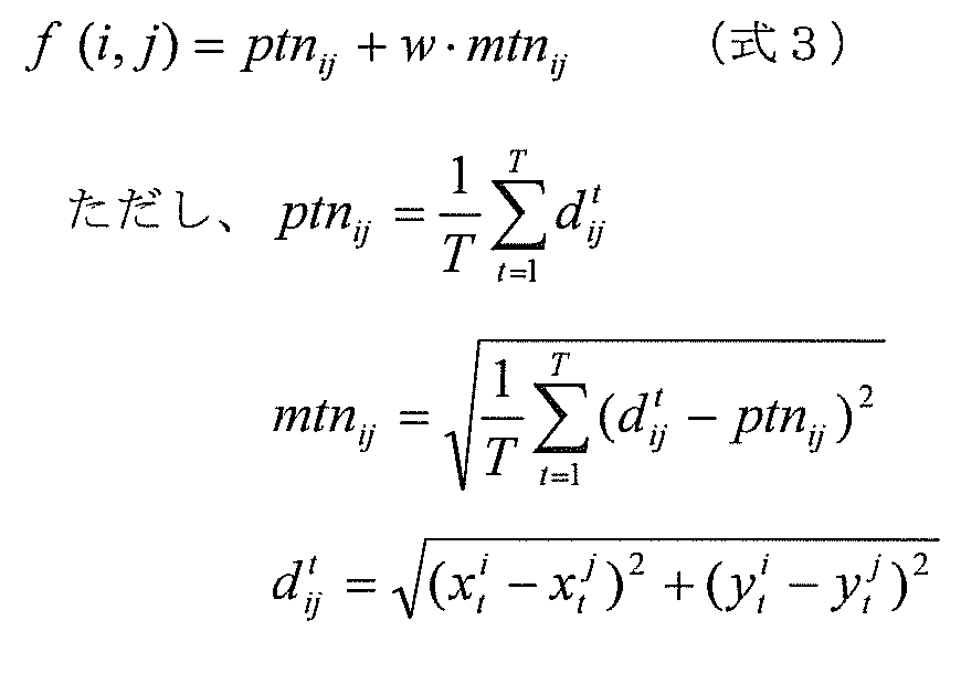
- the distance calculation unit 103 calculates a distance (in this case, an average value of the Euclidean distance) between the movement trajectories by inputting a plurality of movement trajectories.
- the distance f (i, j) between the movement locus of the pixel i and the movement locus of the pixel j can be calculated by the following equation 2.
- Equation 6 min (x, y) is a function that returns the smaller one of the value x and the value y.
- s is a movement trajectory s, which is a relay point for tracing from the movement trajectory i to the movement trajectory j.
- the relay point s in f ′ k (i, s) + f ′ k (s, j) is not limited to one point.
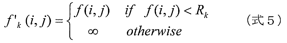
- k corresponds to a plurality of threshold values R k .
- the region division candidate generation unit 107 calculates an I ⁇ I geodetic distance matrix G expressed by the following equation 7. Generate k .
- FIG. 7A shows the data distribution of the movement trajectory x shown in the above equation 1 as a two-dimensional data distribution for convenience of explanation.
- each data point corresponds to the movement trajectory of the pixel i shown in Equation 1 above.
- the relationship of the distance f (i, j) obtained by the above equation 2 is shown in FIG.
- the distance between the data point i and the data point j is smaller than the distance between the data point i and the data point s.
- FIGS. 8A and 8B show an example of the linear distance f (i, j).
- the distance between the pixel i 502 at the head and the pixel j 503 at the hand is the distance indicated by the distance 501.
- a geodetic distance is more suitable than a linear distance to extract the area of the mobile object based on the distance of the movement trajectory. It can be said that.
- the threshold R k is set to a value between the maximum value and the minimum value of f (i, j) and a plurality of geodetic distance matrices are calculated, the number of different clusters of 1 or more and I or less from the geodetic distance matrix is calculated. It is possible to obtain clustering information, that is, candidates for moving object region extraction.
- FIG. 9D An example shown in FIG. 9D will be described for clustering when the threshold value R k is set to a value between the maximum value and the minimum value of f (i, j).
- FIG. 9B when the distance between the movement locus a and the movement locus b is f (a, b), it is assumed that f (d, e)> f (e, g).
- the threshold value is set as R 1
- the distance f (d, e) is than the threshold R 1 having a large value (i.e., f (d, e)> R1) and.
- g 1 (d, e) becomes infinite even if the geodetic distance is obtained by the above equation 6 due to the non-linearization shown in the above equation 5.
- the inter-regional geodetic distance calculation unit 108 performs information on the area division candidates generated in the area division candidate generation step S205, that is, K geodetic distance matrices g k ( i, j) and the corresponding cluster label ⁇ k m and the number of clusters M k are input, and the inter-region geodetic distance corresponding to the plurality of region division candidates is calculated.
- the inter-region geodesic distance calculation unit 108 calculates the number of clusters M (M is 2 or more) from the geodesic distance matrix g k (i, j) corresponding to the K threshold values R k.
- M is 2 or more
- the geodesic distance matrix g k (i, j) corresponding to the K threshold values R k.
- One is arbitrarily selected for each, and this is set as a representative geodetic distance matrix G M representing the number M of clusters.
- the one having the largest threshold Rk is selected from a plurality of geodetic distance matrices having M clusters.
- FIG. 10A is a diagram illustrating an example of a geodetic distance matrix G k obtained for K threshold values R k .
- the geodetic distance matrix is an I ⁇ I geodetic distance matrix in which the geodetic distance g k (i, j) of the movement locus is an element of i rows and j columns.
- Figure 10 (b) ⁇ FIG 10 (d) are diagrams showing an example of a representative geodesic distance matrix G M clusters C 1-3.
- the movement trajectories corresponding to the rows and columns of the representative geodetic distance matrixes of FIGS. 10B to 10D are all common.
- FIG. 10 (b) and FIG. 9 (c), FIG. 10 (c) and FIG. 9 (d), FIG. 10 (d) and FIG. 9 (e) are representative geodesic distances when the number of clusters is 1 to 3, respectively. It is a conceptual diagram of the high-dimensional space of the distance of a matrix and a movement locus.
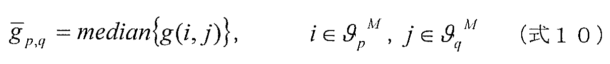
- FIG. 11B the reference matrix clusters corresponding to the clusters ⁇ 1 2 and ⁇ 2 2 of the representative geodetic distance matrix are denoted by ⁇ 1 2 and ⁇ 2 2 (two hatched areas shown in FIG. 11B).
- an element region two vertical line regions in FIG. 11B) whose value is infinite in the representative geodetic distance matrix and whose value is finite in the reference matrix is defined as ⁇ 1,2 2 . .
- the inter-regional geodetic distance calculation unit 108 calculates the inter-regional geodetic distance that is an index of the distance between the clusters. To do.
Landscapes
- Engineering & Computer Science (AREA)
- Multimedia (AREA)
- Computer Vision & Pattern Recognition (AREA)
- Physics & Mathematics (AREA)
- General Physics & Mathematics (AREA)
- Theoretical Computer Science (AREA)
- Image Analysis (AREA)
- Image Processing (AREA)
- Studio Devices (AREA)
Abstract
Description
図1は、実施の形態1における移動体検出装置100の構成を示す図である。図1に示されるように、この移動体検出装置100は、画像入力部101、動き解析部102、距離算出部103、領域分割部104、及び出力部105を備える。ここで、領域分割部104は、測地距離算出部106、領域分割候補生成部107、領域間測地距離算出部108、及び領域分割候補選択部109を備える。移動体検出装置100は、複数枚のピクチャを含む動画像中の移動体の全部又は一部の領域を分割することによって動画像中の移動体を検出する装置である。本実施の形態では、移動体検出装置100は、カメラ110で撮影した動画像を取得し、取得した動画像中の移動体を検出し、検出結果に基づいて画像を生成して出力する。ディスプレイ120は、移動体検出装置100から出力される画像を表示する。
図2は、ソフトウェアによって実現された本実施の形態における移動体検出装置のハードウェア構成を示す図である。図2において、カメラ110は画像を撮影して出力し、コンピュータ1002は画像を取得して領域抽出処理を行って、領域抽出結果を表示する画像を生成する。ディスプレイ120はコンピュータ1002で生成された画像を取得して表示する。コンピュータ1002は、I/F1004、CPU1005、ROM1006、RAM1007、HDD1008、ビデオカード1009で構成される。コンピュータ1002を動作させるプログラムは、ROM1006またはHDD1008にあらかじめ保持されている。プログラムは、プロセッサであるCPU1005によって、ROM1006またはHDD1008からRAM1007に読み出されて展開される。CPU1005はRAM1007に展開されたプログラム中のコード化された各命令を実行する。I/F1004は、プログラムの実行に応じて、カメラ110で撮影された画像を、RAM1007へ取り込む。ビデオカード1009は、プログラムの実行に応じて生成された画像を出力し、ディスプレイ120で表示される。
(非特許文献2)Vladimir Kolmogorov and Ramin Zabih,“Computing Visual Correspondence with Occlusions via Graph Cuts”,International Conference on Computer Vision,2001


(非特許文献4)E.W.Dijkstra,“A note on two problems in connexion with graphs”,Numerische Mathematik,pp.269-271,1959


・2つの領域分割候補の間の距離が大きくなるほど、領域間測地距離も大きくなる。
・移動軌跡全体の大きさ(拡縮率)が変化する場合は、領域間測地距離は一定になる。
・移動体の変形によって、領域分割候補内の移動軌跡間の距離が変動しても、領域間測地距離はあまり変わらない。
たとえば、本実施の形態1の移動体検出装置の領域分割候補選択ステップS207において、閾値Htはあらかじめ定められているものとしたが、これに限定するものではない。具体的には、領域抽出したい移動体の動きの大きさに応じて閾値Htを変化させても良いし、人であるのか車であるのかに応じて閾値Htを変更しても良い。
なお、本実施の形態1の移動体検出装置の領域分割候補生成ステップS205、領域間測地距離算出ステップS206、領域分割候補選択ステップS207の動作として、あらかじめ定められたK個の閾値Rkに対応する領域分割候補を生成したうえで、このK個の領域分割候補から領域間測地距離に基づいて選択するものとして説明した。しかし、本発明の動作はこれに限定されるものではなく、領域分割候補に対応する領域間測地距離を算出し、これに基づいて領域分割候補を選択する動作であれば、どのような手順であっても良い。
また、上記実施の形態1では、領域分割候補選択ステップS207において、領域間測地距離の大きさで、対応する2つの領域分割候補を別個のクラスタとするか否かを判断したが、本発明の領域分割候補の選択基準としては、このような判断基準だけに限るものではなく、例えば、領域間測地距離の時間変化で判断してもよい。
・人物のように多関節状の変形を伴う移動体上の2つの移動軌跡において、移動軌跡間の測地距離の時間変化が小さい。
・多関節状の変形を伴う移動体上の2つの領域分割候補において、領域分割候補間の領域間測地距離の時間変化が小さい。
上記した本実施の形態1では、領域分割候補生成部107は、測地距離算出部106で算出した移動軌跡間の測地距離に基づいて領域分割候補を複数生成するとしたが、領域分割候補を生成する方法をこの方法に限定するものではなく、移動軌跡の集まりである領域分割候補を複数生成する手法であれば、他の方法であっても良い。

・2つの領域分割候補が全く異なる動きをする場合、領域間測地距離の値が大きく、かつ、時間的な変動も大きい。
・2つの領域分割候補が、変形しながら移動する同一移動体上に存在する場合、領域間測地距離の値は比較的小さく、かつ、時間的な変動が小さい(理想的には一定)。
なお、本発明の実施の形態1および実施の形態2では、領域間測地距離は、上記式8および上記式9によって算出するものとしたが、この式に限定するものではない。領域間測地距離は、上記式8および上記式9と同様、2つの領域分割候補間の距離(類似度)を表す指標、および、それぞれの領域分割候補内の移動軌跡のばらつきを表す指標を算出し、距離を表す指標(前者)をばらつきを表す指標(後者)で正規化した指標であればよい。
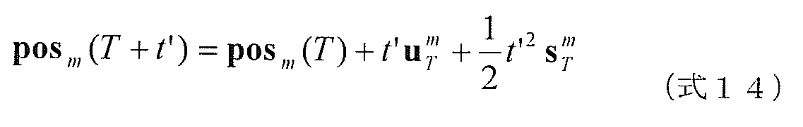
本発明の実施の形態1および実施の形態2では、領域分割の結果はディスプレイに表示されたが、領域分割の結果の利用方法としては、このような応用に限られず、例えば、移動体の動き予測に応用してもよい。具体的には、本発明に係る移動体検出装置は、上記実施の形態における構成要素に加え、動き予測部を備えてもよい。つまり、領域分割部104で得られた領域分割の結果に基づいて、各領域に含まれる画素の移動軌跡から代表軌跡を算出し、その代表軌跡をもとに移動体の動きを予測する動き予測部を備えてもよい。より詳しくは、本発明に係る移動体検出装置は、領域分割部104で特定された領域を構成する移動軌跡から、当該領域を代表する移動軌跡を算出し、算出した代表の移動軌跡に従って当該領域が移動すると予測することで、移動体の動きを予測する動き予測部を備えてもよい。
101 画像入力部
102 動き解析部
103 距離算出部
104 領域分割部
105 出力部
106 測地距離算出部
107 領域分割候補生成部
108 領域間測地距離算出部
109 領域分割候補選択部
110 カメラ
120 ディスプレイ
1002 コンピュータ
1004 I/F
1005 CPU
1006 ROM
1007 RAM
1008 HDD
1009 ビデオカード
Claims (24)
- 動画像中の移動体の全部又は一部の領域を分割することによって動画像中の移動体を検出する方法であって、
動画像を構成する複数の画像間の対応点である移動軌跡を複数取得し、取得した移動軌跡について、移動軌跡間の類似度を表す距離を算出する距離算出ステップと、
前記距離算出ステップで算出された距離に基づいて、類似する移動軌跡の集まりを1つの領域として特定することによって、領域分割をする領域分割ステップとを含み、
前記領域分割ステップは、
前記距離算出ステップで算出された移動軌跡間の距離から、移動軌跡間の測地距離を算出する測地距離算出ステップと、
前記複数の移動軌跡から、移動軌跡の集まりである領域分割候補を複数生成する領域分割候補生成ステップと、
前記領域分割候補生成ステップで生成された領域分割候補について、前記領域分割候補に属する複数の移動軌跡間の測地距離に基づいて、領域分割候補間の類似度を表す領域間測地距離を算出する領域間測地距離算出ステップと、
前記領域分割候補生成ステップで生成された領域分割候補のうち、前記領域間測地距離算出ステップで算出された領域間測地距離が予め定められた条件を満たす領域分割候補を領域分割の結果として選択する領域分割候補選択ステップとを含む
移動体検出方法。 - さらに、
動画像を構成する複数枚のピクチャを受け付ける画像入力ステップと、
前記ピクチャを構成する1個以上の画素からなるブロックごとに、時間的に隣接する2枚のピクチャ間での画像の動きを検出し、検出した動きを前記複数枚のピクチャについて連結することで、移動軌跡を算出する動き解析ステップとを含み、
前記距離算出ステップでは、前記動き解析ステップで算出された移動軌跡を取得し、前記距離を算出する
請求項1記載の移動体検出方法。 - 前記距離算出ステップでは、移動軌跡間の類似度を表す前記距離として、前記複数の画像における移動軌跡間のユークリッド距離の平均値を算出する
請求項1記載の移動体検出方法 - 前記測地距離算出ステップでは、第1の移動軌跡から第2の移動軌跡までの測地距離の算出においては、前記距離算出ステップで取得された複数の移動軌跡のいずれかを中継点として前記第1の移動軌跡から前記第2の移動軌跡に辿りつく全ての経路のうちの最短の経路を、前記測地距離として、算出する
請求項1記載の移動体検出方法。 - 前記測地距離算出ステップでは、
(1)前記距離算出ステップで算出された移動軌跡間の距離に対して、その一部を無限大化することで非線形化した距離を算出し、(2)前記非線形化した距離に基づいた、第1の移動軌跡から第2の移動軌跡までの測地距離の算出において、他の移動軌跡を中継点として、前記第1の移動軌跡から前記第2の移動軌跡に辿りつく全ての経路の距離うちの最短の距離を、前記測地距離として算出する
請求項4記載の移動体検出方法。 - 前記測地距離算出ステップでは、複数の閾値を取得し、取得した複数の閾値を、移動軌跡の近傍を定義する閾値として用いて、前記距離算出ステップで算出された移動軌跡間の距離から、それぞれの閾値ごとに、近傍にある移動軌跡を辿っていく経路における距離を算出することで、前記移動軌跡間の測地距離を算出し、
前記領域分割候補生成ステップでは、前記測地距離算出ステップで算出した複数の閾値ごとの移動軌跡間の測地距離に基づいて、類似する移動軌跡の集まりを1つの領域分割候補とすることで、前記複数の領域分割候補を生成する
請求項1記載の移動体検出方法。 - 前記測地距離算出ステップでは、前記複数の閾値として、前記距離算出ステップで算出された複数の距離のうちの最大値と最小値との間の値を生成する
請求項6記載の移動体検出方法。 - 前記領域間測地距離算出ステップでは、前記複数の閾値のそれぞれに対して前記領域分割候補生成ステップで生成された複数の領域分割候補のセットのうちの第1の領域分割候補のセットにおける2つの領域分割候補間の領域間測地距離として、当該2つの領域分割候補における測地距離である代表測地距離と、当該第1の領域分割候補のセットに含まれる領域分割候補の総数よりも次に小さい総数だけ領域分割候補が含まれる第2の領域分割候補のセットにおける測地距離である参照測地距離とを用いて、予め定められた演算をすることで、算出する
請求項1記載の移動体検出方法。 - 前記領域間測地距離算出ステップでは、前記参照測地距離と前記代表測地距離とに基づいて、2つの領域分割候補間の距離を表す指標と、各領域分割候補内のばらつきを表す指標とを算出し、前記距離を表す指標を、前記ばらつきを表す指標で正規化する演算をすることで、前記領域間測地距離を算出する
請求項8記載の移動体検出方法。 - 前記領域間測地距離算出ステップで算出される領域間測地距離は、ある領域分割候補に属する複数の移動軌跡と他の領域分割候補に属する複数の移動軌跡との間の測地距離の総和から算出した2つの領域分割候補間の距離を表す指標を、前記ある領域分割候補に属する複数の移動軌跡間の測地距離の総和から算出した領域分割候補内のばらつきを表す指標と、前記他の領域分割候補に属する複数の移動軌跡間の測地距離の総和から算出した領域分割候補内のばらつきを表す指標とを用いて、正規化した値である
請求項1記載の移動体検出方法。 - 前記領域分割候補選択ステップでは、前記領域分割候補生成ステップで生成された領域分割候補のうち、前記領域間測地距離算出ステップで算出された領域間測地距離が予め定められた閾値よりも大きい2つの領域分割候補の全てを、前記領域分割の結果として選択し、出力する
請求項1記載の移動体検出方法。 - 前記領域分割候補選択ステップでは、前記領域分割候補生成ステップで生成された領域分割候補のうち、前記領域間測地距離算出ステップで算出された領域間測地距離の時間変化に基づいて、前記領域分割候補を選択し、前記領域分割の結果として出力する
請求項1記載の移動体検出方法。 - 前記領域分割候補選択ステップでは、前記領域分割候補生成ステップで生成された領域分割候補のうち、前記領域間測地距離算出ステップで算出された領域間測地距離の時間変化が、予め定められた閾値より大きい2つの領域分割候補を、異なる領域として選択し、前記領域分割の結果として出力する
請求項12記載の移動体検出方法。 - 前記領域分割候補選択ステップでは、前記領域分割候補生成ステップで生成された領域分割候補のうち、前記領域間測地距離算出ステップで算出された領域間測地距離の時間変化が、予め定められた閾値より小さい2つの領域分割候補を、同一の領域として選択し、前記領域分割の結果として出力する
請求項12記載の移動体検出方法。 - 前記領域分割候補選択ステップでは、前記領域分割候補生成ステップで生成された領域分割候補のうち、前記領域間測地距離算出ステップで算出された領域間測地距離の時間変化に基づいて、(1)大きいほど2つの領域分割候補は異なる領域となるように、かつ、(2)小さいほど2つの領域分割候補を同一の領域となるように領域分割候補を選択し、前記領域分割の結果として出力する
請求項12記載の移動体検出方法。 - 前記距離算出ステップ及び前記領域分割ステップは、新たな動画像について、繰り返し実行され、
前記領域分割候補選択ステップでは、前記領域分割候補生成ステップで生成された領域分割候補のうち、前記繰り返し実行において前記領域間測地距離算出ステップで算出された領域間測地距離の時間変化が予め定められた閾値よりも大きい2つの領域分割候補の全てを、前記領域分割の結果として選択し、出力する
請求項12記載の移動体検出方法。 - 前記領域分割候補生成ステップでは、前記画像入力ステップで取得した画像の輝度情報に基づいて、複数の領域分割候補画像を生成し、領域分割候補画像に対応する1つ以上の移動軌跡の集まりを領域分割候補とすることで、前記複数の領域分割候補を生成する
請求項2記載の移動体検出方法。 - 前記領域分割候補生成ステップで生成される複数の領域分割候補のうち、少なくとも1つの領域分割候補は1個の移動軌跡が属するものであり、
前記領域間測地距離算出ステップでは、前記1個の移動軌跡が属する領域分割候補と他の領域分割候補との領域間測地距離として、前記1個の移動軌跡と前記他の領域分割候補に属する任意の1つの移動軌跡との測地距離を出力する
請求項1記載の移動体検出方法。 - 前記領域分割候補選択ステップでは、前記領域間測地距離として出力された移動軌跡間の測地距離の時間変化が、予め定められた閾値より小さい2つの移動軌跡を、同じ領域として特定する
請求項18記載の移動体検出方法。 - 前記領域分割候補選択ステップでは、前記領域間測地距離として出力された移動軌跡間の測地距離の時間変化が、予め定められた閾値より大きい2つの移動軌跡を、異なる領域として特定する
請求項18記載の移動体検出方法。 - さらに、前記画像入力ステップで受け付けた動画像に対して、前記領域分割ステップで特定された領域ごとに異なる表示態様となるように、画像処理を施し、出力する出力ステップを含む
請求項2記載の移動体検出方法。 - さらに、前記領域分割ステップで特定された領域を構成する移動軌跡から、当該領域を代表する移動軌跡を算出し、算出した代表の移動軌跡に従って当該領域が移動すると予測することで、前記移動体の動きを予測する動き予測ステップを含む
請求項1記載の移動体検出方法。 - 動画像中の移動体の全部又は一部の領域を分割することによって動画像中の移動体を検出する装置であって、
動画像を構成する複数の画像間の対応点である移動軌跡を複数取得し、取得した移動軌跡について、移動軌跡間の類似度を表す距離を算出する距離算出部と、
前記距離算出部で算出された距離に基づいて、類似する移動軌跡の集まりを1つの領域として特定することによって、領域分割をする領域分割部とを備え、
前記領域分割部は、
前記距離算出部で算出された移動軌跡間の距離から、移動軌跡間の測地距離を算出する測地距離算出部と、
前記複数の移動軌跡から、移動軌跡の集まりである領域分割候補を複数生成する領域分割候補生成部と、
前記領域分割候補生成部で生成された領域分割候補について、前記領域分割候補に属する複数の移動軌跡間の測地距離に基づいて、領域分割候補間の類似度を表す領域間測地距離を算出する領域間測地距離算出部と、
前記領域分割候補生成部で生成された領域分割候補のうち、前記領域間測地距離算出部で算出された領域間測地距離が予め定められた条件を満たす領域分割候補を領域分割の結果として選択する領域分割候補選択部とを有する
移動体検出装置。 - 動画像中の移動体の全部又は一部の領域を分割することによって動画像中の移動体を検出する移動体検出装置のためのプログラムであって、
請求項1記載の移動体検出方法に含まれるステップをコンピュータに実行させる
プログラム。
Priority Applications (4)
| Application Number | Priority Date | Filing Date | Title |
|---|---|---|---|
| CN200980125394.0A CN102077250B (zh) | 2009-01-09 | 2009-12-18 | 移动体检测方法及移动体检测装置 |
| US12/920,180 US8213681B2 (en) | 2009-01-09 | 2009-12-18 | Moving object detection method and moving object detection apparatus |
| JP2010513554A JP4542207B1 (ja) | 2009-01-09 | 2009-12-18 | 移動体検出方法および移動体検出装置 |
| EP09837446.5A EP2378485B1 (en) | 2009-01-09 | 2009-12-18 | Moving object detection method and moving object detection apparatus |
Applications Claiming Priority (4)
| Application Number | Priority Date | Filing Date | Title |
|---|---|---|---|
| JP2009-004083 | 2009-01-09 | ||
| JP2009004083 | 2009-01-09 | ||
| JP2009-209860 | 2009-09-10 | ||
| JP2009209860 | 2009-09-10 |
Publications (1)
| Publication Number | Publication Date |
|---|---|
| WO2010079556A1 true WO2010079556A1 (ja) | 2010-07-15 |
Family
ID=42316335
Family Applications (1)
| Application Number | Title | Priority Date | Filing Date |
|---|---|---|---|
| PCT/JP2009/006999 Ceased WO2010079556A1 (ja) | 2009-01-09 | 2009-12-18 | 移動体検出方法および移動体検出装置 |
Country Status (5)
| Country | Link |
|---|---|
| US (1) | US8213681B2 (ja) |
| EP (1) | EP2378485B1 (ja) |
| JP (1) | JP4542207B1 (ja) |
| CN (1) | CN102077250B (ja) |
| WO (1) | WO2010079556A1 (ja) |
Cited By (11)
| Publication number | Priority date | Publication date | Assignee | Title |
|---|---|---|---|---|
| WO2011080923A1 (ja) * | 2009-12-28 | 2011-07-07 | パナソニック株式会社 | 関節状領域検出装置およびその方法 |
| CN102222157A (zh) * | 2011-04-28 | 2011-10-19 | 华南理工大学 | 一种基于人工势场法的动态预警域生成方法 |
| WO2012014430A1 (ja) * | 2010-07-27 | 2012-02-02 | パナソニック株式会社 | 移動体検出装置および移動体検出方法 |
| WO2012101723A1 (ja) * | 2011-01-26 | 2012-08-02 | パナソニック株式会社 | 関節領域表示装置、関節領域検出装置、関節領域帰属度算出装置、関節状領域帰属度算出装置および関節領域表示方法 |
| KR101313879B1 (ko) | 2011-12-28 | 2013-10-01 | 대전대학교 산학협력단 | 기울기 히스토그램을 이용한 사람 검출 추적 시스템 및 방법 |
| JP2013228259A (ja) * | 2012-04-25 | 2013-11-07 | Toyota Motor Corp | 物体識別装置及び物体識別方法 |
| US8605946B2 (en) | 2011-03-22 | 2013-12-10 | Panasonic Corporation | Moving object detection apparatus and moving object detection method |
| JP2015531095A (ja) * | 2012-06-06 | 2015-10-29 | グーグル インコーポレイテッド | 障害物評価技術 |
| US9236090B2 (en) | 2012-07-20 | 2016-01-12 | Panasonic Intellectual Property Management Co., Ltd. | Video generating apparatus and video generating method |
| JP2018106360A (ja) * | 2016-12-26 | 2018-07-05 | キヤノン株式会社 | 情報処理装置、情報処理方法及びプログラム |
| JP2020021243A (ja) * | 2018-07-31 | 2020-02-06 | グローリー株式会社 | 画像処理装置、画像処理方法、および、画像処理プログラム |
Families Citing this family (26)
| Publication number | Priority date | Publication date | Assignee | Title |
|---|---|---|---|---|
| ATE538453T1 (de) * | 2008-03-14 | 2012-01-15 | Panasonic Corp | Bildverarbeitungsverfahren und bildverarbeitungsvorrichtung |
| US8605942B2 (en) * | 2009-02-26 | 2013-12-10 | Nikon Corporation | Subject tracking apparatus, imaging apparatus and subject tracking method |
| CN102473307B (zh) * | 2010-03-15 | 2015-05-27 | 松下电器产业株式会社 | 用于轨迹估计的方法和装置以及用于分割的方法 |
| JP2011199716A (ja) * | 2010-03-23 | 2011-10-06 | Sony Corp | 画像処理装置、および画像処理方法、並びにプログラム |
| JP2012151796A (ja) * | 2011-01-21 | 2012-08-09 | Sony Corp | 画像処理装置と画像処理方法およびプログラム |
| KR101901958B1 (ko) * | 2012-03-26 | 2018-11-08 | 한국전자통신연구원 | 휴리스틱 함수의 학습을 이용한 고속 경로를 탐색을 위한 장치 및 그 방법 |
| JP2014186547A (ja) * | 2013-03-22 | 2014-10-02 | Toshiba Corp | 移動物体追跡システム、方法及びプログラム |
| US9213901B2 (en) * | 2013-09-04 | 2015-12-15 | Xerox Corporation | Robust and computationally efficient video-based object tracking in regularized motion environments |
| US9405974B2 (en) * | 2013-11-13 | 2016-08-02 | Xerox Corporation | System and method for using apparent size and orientation of an object to improve video-based tracking in regularized environments |
| US11501244B1 (en) | 2015-04-06 | 2022-11-15 | Position Imaging, Inc. | Package tracking systems and methods |
| US10148918B1 (en) | 2015-04-06 | 2018-12-04 | Position Imaging, Inc. | Modular shelving systems for package tracking |
| US11416805B1 (en) | 2015-04-06 | 2022-08-16 | Position Imaging, Inc. | Light-based guidance for package tracking systems |
| US10853757B1 (en) | 2015-04-06 | 2020-12-01 | Position Imaging, Inc. | Video for real-time confirmation in package tracking systems |
| CN107798272B (zh) * | 2016-08-30 | 2021-11-02 | 佳能株式会社 | 快速多目标检测与跟踪系统 |
| US11436553B2 (en) | 2016-09-08 | 2022-09-06 | Position Imaging, Inc. | System and method of object tracking using weight confirmation |
| US10634506B2 (en) | 2016-12-12 | 2020-04-28 | Position Imaging, Inc. | System and method of personalized navigation inside a business enterprise |
| US10634503B2 (en) * | 2016-12-12 | 2020-04-28 | Position Imaging, Inc. | System and method of personalized navigation inside a business enterprise |
| US12190542B2 (en) | 2017-01-06 | 2025-01-07 | Position Imaging, Inc. | System and method of calibrating a directional light source relative to a camera's field of view |
| US11120392B2 (en) | 2017-01-06 | 2021-09-14 | Position Imaging, Inc. | System and method of calibrating a directional light source relative to a camera's field of view |
| EP3853772A4 (en) | 2018-09-21 | 2022-06-22 | Position Imaging, Inc. | MACHINE LEARNING ASSISTED SELF-IMPROVING SYSTEM AND METHOD FOR OBJECT IDENTIFICATION |
| US11089232B2 (en) | 2019-01-11 | 2021-08-10 | Position Imaging, Inc. | Computer-vision-based object tracking and guidance module |
| DE112019007455T5 (de) * | 2019-07-19 | 2022-03-03 | Mitsubishi Electric Corporation | Anzeigeverarbeitungsvorrichtung, anzeigeverarbeitungsverfahren und programm |
| US10911677B1 (en) * | 2019-09-09 | 2021-02-02 | Apple Inc. | Multi-camera video stabilization techniques |
| JP7463146B2 (ja) * | 2020-03-17 | 2024-04-08 | 本田技研工業株式会社 | 移動体監視システム、及び移動体監視方法 |
| CN115131392B (zh) * | 2022-08-31 | 2022-12-06 | 中国科学院空天信息创新研究院 | 基于天基光学观测图像的空间运动目标检测跟踪方法 |
| CN119458383B (zh) * | 2025-01-14 | 2025-03-25 | 浙江嘉润环保科技有限公司 | 基于声呐图像的恶劣环境清淤机器人路径规划方法及系统 |
Citations (7)
| Publication number | Priority date | Publication date | Assignee | Title |
|---|---|---|---|---|
| JPH08214289A (ja) | 1994-12-06 | 1996-08-20 | Olympus Optical Co Ltd | 時系列画像解析装置及びその解析方法 |
| JPH1166319A (ja) * | 1997-08-21 | 1999-03-09 | Omron Corp | 移動体検出方法及び装置並びに移動体認識方法及び装置並びに人間検出方法及び装置 |
| JP2000222584A (ja) * | 1999-01-29 | 2000-08-11 | Toshiba Corp | 映像情報記述方法、映像検索方法及び映像検索装置 |
| JP2005332206A (ja) * | 2004-05-20 | 2005-12-02 | Nippon Hoso Kyokai <Nhk> | 映像イベント判別装置及びそのプログラム、並びに、映像イベント判別用学習データ生成装置及びそのプログラム |
| JP2006031114A (ja) | 2004-07-12 | 2006-02-02 | Hitachi Software Eng Co Ltd | 画像分割処理システム |
| JP2007087049A (ja) * | 2005-09-21 | 2007-04-05 | Kddi Corp | 動画像処理装置 |
| JP4456181B1 (ja) * | 2008-10-27 | 2010-04-28 | パナソニック株式会社 | 移動体検出方法及び移動体検出装置 |
Family Cites Families (8)
| Publication number | Priority date | Publication date | Assignee | Title |
|---|---|---|---|---|
| JP3612360B2 (ja) * | 1995-04-10 | 2005-01-19 | 株式会社大宇エレクトロニクス | 移動物体分割法を用いた動画像の動き推定方法 |
| US6643387B1 (en) * | 1999-01-28 | 2003-11-04 | Sarnoff Corporation | Apparatus and method for context-based indexing and retrieval of image sequences |
| JP4226730B2 (ja) * | 1999-01-28 | 2009-02-18 | 株式会社東芝 | 物体領域情報生成方法及び物体領域情報生成装置並びに映像情報処理方法及び情報処理装置 |
| US6859554B2 (en) * | 2001-04-04 | 2005-02-22 | Mitsubishi Electric Research Laboratories, Inc. | Method for segmenting multi-resolution video objects |
| US20030123704A1 (en) * | 2001-05-30 | 2003-07-03 | Eaton Corporation | Motion-based image segmentor for occupant tracking |
| JP4480299B2 (ja) * | 2001-06-21 | 2010-06-16 | 富士通マイクロエレクトロニクス株式会社 | 移動体を含む画像の処理方法及び装置 |
| US8614741B2 (en) * | 2003-03-31 | 2013-12-24 | Alcatel Lucent | Method and apparatus for intelligent and automatic sensor control using multimedia database system |
| CN101324922B (zh) * | 2008-07-30 | 2012-04-18 | 北京中星微电子有限公司 | 手指尖轨迹获取方法和装置 |
-
2009
- 2009-12-18 CN CN200980125394.0A patent/CN102077250B/zh not_active Expired - Fee Related
- 2009-12-18 US US12/920,180 patent/US8213681B2/en not_active Expired - Fee Related
- 2009-12-18 WO PCT/JP2009/006999 patent/WO2010079556A1/ja not_active Ceased
- 2009-12-18 JP JP2010513554A patent/JP4542207B1/ja not_active Expired - Fee Related
- 2009-12-18 EP EP09837446.5A patent/EP2378485B1/en not_active Not-in-force
Patent Citations (7)
| Publication number | Priority date | Publication date | Assignee | Title |
|---|---|---|---|---|
| JPH08214289A (ja) | 1994-12-06 | 1996-08-20 | Olympus Optical Co Ltd | 時系列画像解析装置及びその解析方法 |
| JPH1166319A (ja) * | 1997-08-21 | 1999-03-09 | Omron Corp | 移動体検出方法及び装置並びに移動体認識方法及び装置並びに人間検出方法及び装置 |
| JP2000222584A (ja) * | 1999-01-29 | 2000-08-11 | Toshiba Corp | 映像情報記述方法、映像検索方法及び映像検索装置 |
| JP2005332206A (ja) * | 2004-05-20 | 2005-12-02 | Nippon Hoso Kyokai <Nhk> | 映像イベント判別装置及びそのプログラム、並びに、映像イベント判別用学習データ生成装置及びそのプログラム |
| JP2006031114A (ja) | 2004-07-12 | 2006-02-02 | Hitachi Software Eng Co Ltd | 画像分割処理システム |
| JP2007087049A (ja) * | 2005-09-21 | 2007-04-05 | Kddi Corp | 動画像処理装置 |
| JP4456181B1 (ja) * | 2008-10-27 | 2010-04-28 | パナソニック株式会社 | 移動体検出方法及び移動体検出装置 |
Non-Patent Citations (5)
| Title |
|---|
| E.W.DIJKSTRA: "A note on two problems in connexion with graphs", NUMERISCHE MATHEMATIK, 1959, pages 269 - 271, XP000837527, DOI: doi:10.1007/BF01386390 |
| JOSHUA TENENBAUM; VIN DE SILVA; JOHN LANGFORD: "A Global Geometric Framework for Nonlinear Dimensionality Reduction", SCIENCE, vol. 290, 22 December 2000 (2000-12-22), pages 2319 - 2322 |
| P. ANANDAN: "A Computational Framework and an Algorithm for the Measurement of Visual Motion", INTERNATIONAL JOURNAL OF COMPUTER VISION, vol. 2, 1989, pages 283 - 310, XP008055537, DOI: doi:10.1007/BF00158167 |
| PEDRO F. FEIZENSZWALB; DANIEL P. HUTTENLOCHER: "Efficient Graph-Based Image Segmentation", INTERNATIONAL JOURNAL OF COMPUTER VISION, vol. 59, no. 2, September 2004 (2004-09-01), pages 167 - 181, XP055013351, DOI: doi:10.1023/B:VISI.0000022288.19776.77 |
| VLADIMIR KOLMOGOROV; RAMIN ZABIH: "Computing Visual Correspondence with Occlusions via Graph Cuts", INTERNATIONAL CONFERENCE ON COMPUTER VISION, 2001 |
Cited By (24)
| Publication number | Priority date | Publication date | Assignee | Title |
|---|---|---|---|---|
| US8401243B2 (en) | 2009-12-28 | 2013-03-19 | Panasonic Corporation | Articulated object region detection apparatus and method of the same |
| JP4763863B1 (ja) * | 2009-12-28 | 2011-08-31 | パナソニック株式会社 | 関節状領域検出装置およびその方法 |
| WO2011080923A1 (ja) * | 2009-12-28 | 2011-07-07 | パナソニック株式会社 | 関節状領域検出装置およびその方法 |
| CN102741884B (zh) * | 2010-07-27 | 2016-06-08 | 松下知识产权经营株式会社 | 移动体检测装置及移动体检测方法 |
| WO2012014430A1 (ja) * | 2010-07-27 | 2012-02-02 | パナソニック株式会社 | 移動体検出装置および移動体検出方法 |
| JP4979840B2 (ja) * | 2010-07-27 | 2012-07-18 | パナソニック株式会社 | 移動体検出装置および移動体検出方法 |
| US8599252B2 (en) | 2010-07-27 | 2013-12-03 | Panasonic Corporation | Moving object detection apparatus and moving object detection method |
| CN102741884A (zh) * | 2010-07-27 | 2012-10-17 | 松下电器产业株式会社 | 移动体检测装置及移动体检测方法 |
| JP4994525B1 (ja) * | 2011-01-26 | 2012-08-08 | パナソニック株式会社 | 関節領域表示装置、関節領域検出装置、関節領域帰属度算出装置、関節状領域帰属度算出装置および関節領域表示方法 |
| CN103003846B (zh) * | 2011-01-26 | 2016-07-06 | 松下知识产权经营株式会社 | 关节区域显示装置、关节区域检测装置、关节区域归属度计算装置、关节状区域归属度计算装置以及关节区域显示方法 |
| CN103003846A (zh) * | 2011-01-26 | 2013-03-27 | 松下电器产业株式会社 | 关节区域显示装置、关节区域检测装置、关节区域归属度计算装置、关节状区域归属度计算装置以及关节区域显示方法 |
| US8929599B2 (en) | 2011-01-26 | 2015-01-06 | Panasonic Corporation | Articulation region display apparatus, articulation region detecting apparatus, articulation region belongingness calculating apparatus, articulated object region belongingness calculating apparatus, and articulation region display method |
| WO2012101723A1 (ja) * | 2011-01-26 | 2012-08-02 | パナソニック株式会社 | 関節領域表示装置、関節領域検出装置、関節領域帰属度算出装置、関節状領域帰属度算出装置および関節領域表示方法 |
| US8605946B2 (en) | 2011-03-22 | 2013-12-10 | Panasonic Corporation | Moving object detection apparatus and moving object detection method |
| CN102222157A (zh) * | 2011-04-28 | 2011-10-19 | 华南理工大学 | 一种基于人工势场法的动态预警域生成方法 |
| CN102222157B (zh) * | 2011-04-28 | 2013-10-30 | 华南理工大学 | 一种基于人工势场法的动态预警域生成方法 |
| KR101313879B1 (ko) | 2011-12-28 | 2013-10-01 | 대전대학교 산학협력단 | 기울기 히스토그램을 이용한 사람 검출 추적 시스템 및 방법 |
| JP2013228259A (ja) * | 2012-04-25 | 2013-11-07 | Toyota Motor Corp | 物体識別装置及び物体識別方法 |
| JP2015531095A (ja) * | 2012-06-06 | 2015-10-29 | グーグル インコーポレイテッド | 障害物評価技術 |
| KR101763261B1 (ko) * | 2012-06-06 | 2017-07-31 | 구글 인코포레이티드 | 장애물 평가 기법 |
| US9236090B2 (en) | 2012-07-20 | 2016-01-12 | Panasonic Intellectual Property Management Co., Ltd. | Video generating apparatus and video generating method |
| JP2018106360A (ja) * | 2016-12-26 | 2018-07-05 | キヤノン株式会社 | 情報処理装置、情報処理方法及びプログラム |
| JP2020021243A (ja) * | 2018-07-31 | 2020-02-06 | グローリー株式会社 | 画像処理装置、画像処理方法、および、画像処理プログラム |
| JP7130488B2 (ja) | 2018-07-31 | 2022-09-05 | グローリー株式会社 | 画像処理装置、画像処理方法、および、画像処理プログラム |
Also Published As
| Publication number | Publication date |
|---|---|
| CN102077250B (zh) | 2014-04-16 |
| JP4542207B1 (ja) | 2010-09-08 |
| CN102077250A (zh) | 2011-05-25 |
| EP2378485A4 (en) | 2013-07-24 |
| JPWO2010079556A1 (ja) | 2012-06-21 |
| US8213681B2 (en) | 2012-07-03 |
| EP2378485B1 (en) | 2018-04-11 |
| US20110002509A1 (en) | 2011-01-06 |
| EP2378485A1 (en) | 2011-10-19 |
Similar Documents
| Publication | Publication Date | Title |
|---|---|---|
| JP4542207B1 (ja) | 移動体検出方法および移動体検出装置 | |
| JP4456181B1 (ja) | 移動体検出方法及び移動体検出装置 | |
| JP4643766B1 (ja) | 移動体検出装置及び移動体検出方法 | |
| JP4782901B2 (ja) | 移動体検出装置および移動体検出方法 | |
| JP4668360B2 (ja) | 移動体検出方法及び移動体検出装置 | |
| JP4763863B1 (ja) | 関節状領域検出装置およびその方法 | |
| JP5054206B2 (ja) | 画像処理方法及び画像処理装置 | |
| JP4496992B2 (ja) | 動物体アップフレーム検出方法及びプログラム及びプログラムを格納した記憶媒体及び動物体アップショット検出方法及び動物体アップフレームあるいはショット検出方法及びプログラム及びプログラムを格納した記憶媒体 | |
| JP4966946B2 (ja) | 時空間画像分離装置、時空間画像分離方法および時空間画像分離プログラム |
Legal Events
| Date | Code | Title | Description |
|---|---|---|---|
| WWE | Wipo information: entry into national phase |
Ref document number: 200980125394.0 Country of ref document: CN |
|
| WWE | Wipo information: entry into national phase |
Ref document number: 2010513554 Country of ref document: JP |
|
| WWE | Wipo information: entry into national phase |
Ref document number: 12920180 Country of ref document: US |
|
| 121 | Ep: the epo has been informed by wipo that ep was designated in this application |
Ref document number: 09837446 Country of ref document: EP Kind code of ref document: A1 |
|
| WWE | Wipo information: entry into national phase |
Ref document number: 2009837446 Country of ref document: EP |
|
| NENP | Non-entry into the national phase |
Ref country code: DE |