WO2010082580A1 - 混練ロータ、バッチ式混練機および材料混練方法 - Google Patents
混練ロータ、バッチ式混練機および材料混練方法 Download PDFInfo
- Publication number
- WO2010082580A1 WO2010082580A1 PCT/JP2010/050267 JP2010050267W WO2010082580A1 WO 2010082580 A1 WO2010082580 A1 WO 2010082580A1 JP 2010050267 W JP2010050267 W JP 2010050267W WO 2010082580 A1 WO2010082580 A1 WO 2010082580A1
- Authority
- WO
- WIPO (PCT)
- Prior art keywords
- kneading
- rotor
- rotor portion
- blade
- tip clearance
- Prior art date
- Legal status (The legal status is an assumption and is not a legal conclusion. Google has not performed a legal analysis and makes no representation as to the accuracy of the status listed.)
- Ceased
Links
Images




Classifications
-
- B—PERFORMING OPERATIONS; TRANSPORTING
- B29—WORKING OF PLASTICS; WORKING OF SUBSTANCES IN A PLASTIC STATE IN GENERAL
- B29B—PREPARATION OR PRETREATMENT OF THE MATERIAL TO BE SHAPED; MAKING GRANULES OR PREFORMS; RECOVERY OF PLASTICS OR OTHER CONSTITUENTS OF WASTE MATERIAL CONTAINING PLASTICS
- B29B7/00—Mixing; Kneading
- B29B7/02—Mixing; Kneading non-continuous, with mechanical mixing or kneading devices, i.e. batch type
- B29B7/06—Mixing; Kneading non-continuous, with mechanical mixing or kneading devices, i.e. batch type with movable mixing or kneading devices
- B29B7/10—Mixing; Kneading non-continuous, with mechanical mixing or kneading devices, i.e. batch type with movable mixing or kneading devices rotary
- B29B7/18—Mixing; Kneading non-continuous, with mechanical mixing or kneading devices, i.e. batch type with movable mixing or kneading devices rotary with more than one shaft
-
- B—PERFORMING OPERATIONS; TRANSPORTING
- B29—WORKING OF PLASTICS; WORKING OF SUBSTANCES IN A PLASTIC STATE IN GENERAL
- B29B—PREPARATION OR PRETREATMENT OF THE MATERIAL TO BE SHAPED; MAKING GRANULES OR PREFORMS; RECOVERY OF PLASTICS OR OTHER CONSTITUENTS OF WASTE MATERIAL CONTAINING PLASTICS
- B29B7/00—Mixing; Kneading
- B29B7/02—Mixing; Kneading non-continuous, with mechanical mixing or kneading devices, i.e. batch type
- B29B7/06—Mixing; Kneading non-continuous, with mechanical mixing or kneading devices, i.e. batch type with movable mixing or kneading devices
- B29B7/10—Mixing; Kneading non-continuous, with mechanical mixing or kneading devices, i.e. batch type with movable mixing or kneading devices rotary
- B29B7/18—Mixing; Kneading non-continuous, with mechanical mixing or kneading devices, i.e. batch type with movable mixing or kneading devices rotary with more than one shaft
- B29B7/183—Mixing; Kneading non-continuous, with mechanical mixing or kneading devices, i.e. batch type with movable mixing or kneading devices rotary with more than one shaft having a casing closely surrounding the rotors, e.g. of Banbury type
- B29B7/186—Rotors therefor
-
- B—PERFORMING OPERATIONS; TRANSPORTING
- B01—PHYSICAL OR CHEMICAL PROCESSES OR APPARATUS IN GENERAL
- B01F—MIXING, e.g. DISSOLVING, EMULSIFYING OR DISPERSING
- B01F27/00—Mixers with rotary stirring devices in fixed receptacles; Kneaders
- B01F27/60—Mixers with rotary stirring devices in fixed receptacles; Kneaders with stirrers rotating about a horizontal or inclined axis
- B01F27/72—Mixers with rotary stirring devices in fixed receptacles; Kneaders with stirrers rotating about a horizontal or inclined axis with helices or sections of helices
-
- B—PERFORMING OPERATIONS; TRANSPORTING
- B29—WORKING OF PLASTICS; WORKING OF SUBSTANCES IN A PLASTIC STATE IN GENERAL
- B29B—PREPARATION OR PRETREATMENT OF THE MATERIAL TO BE SHAPED; MAKING GRANULES OR PREFORMS; RECOVERY OF PLASTICS OR OTHER CONSTITUENTS OF WASTE MATERIAL CONTAINING PLASTICS
- B29B7/00—Mixing; Kneading
- B29B7/02—Mixing; Kneading non-continuous, with mechanical mixing or kneading devices, i.e. batch type
- B29B7/06—Mixing; Kneading non-continuous, with mechanical mixing or kneading devices, i.e. batch type with movable mixing or kneading devices
- B29B7/10—Mixing; Kneading non-continuous, with mechanical mixing or kneading devices, i.e. batch type with movable mixing or kneading devices rotary
- B29B7/18—Mixing; Kneading non-continuous, with mechanical mixing or kneading devices, i.e. batch type with movable mixing or kneading devices rotary with more than one shaft
- B29B7/183—Mixing; Kneading non-continuous, with mechanical mixing or kneading devices, i.e. batch type with movable mixing or kneading devices rotary with more than one shaft having a casing closely surrounding the rotors, e.g. of Banbury type
-
- B—PERFORMING OPERATIONS; TRANSPORTING
- B29—WORKING OF PLASTICS; WORKING OF SUBSTANCES IN A PLASTIC STATE IN GENERAL
- B29B—PREPARATION OR PRETREATMENT OF THE MATERIAL TO BE SHAPED; MAKING GRANULES OR PREFORMS; RECOVERY OF PLASTICS OR OTHER CONSTITUENTS OF WASTE MATERIAL CONTAINING PLASTICS
- B29B7/00—Mixing; Kneading
- B29B7/02—Mixing; Kneading non-continuous, with mechanical mixing or kneading devices, i.e. batch type
- B29B7/22—Component parts, details or accessories; Auxiliary operations
- B29B7/24—Component parts, details or accessories; Auxiliary operations for feeding
- B29B7/246—Component parts, details or accessories; Auxiliary operations for feeding in mixers having more than one rotor and a casing closely surrounding the rotors, e.g. with feeding plungers
-
- B—PERFORMING OPERATIONS; TRANSPORTING
- B29—WORKING OF PLASTICS; WORKING OF SUBSTANCES IN A PLASTIC STATE IN GENERAL
- B29B—PREPARATION OR PRETREATMENT OF THE MATERIAL TO BE SHAPED; MAKING GRANULES OR PREFORMS; RECOVERY OF PLASTICS OR OTHER CONSTITUENTS OF WASTE MATERIAL CONTAINING PLASTICS
- B29B7/00—Mixing; Kneading
- B29B7/02—Mixing; Kneading non-continuous, with mechanical mixing or kneading devices, i.e. batch type
- B29B7/22—Component parts, details or accessories; Auxiliary operations
- B29B7/26—Component parts, details or accessories; Auxiliary operations for discharging, e.g. doors
- B29B7/263—Component parts, details or accessories; Auxiliary operations for discharging, e.g. doors from the underside in mixers having more than one rotor and a a casing closely surrounding the rotors
-
- B—PERFORMING OPERATIONS; TRANSPORTING
- B29—WORKING OF PLASTICS; WORKING OF SUBSTANCES IN A PLASTIC STATE IN GENERAL
- B29B—PREPARATION OR PRETREATMENT OF THE MATERIAL TO BE SHAPED; MAKING GRANULES OR PREFORMS; RECOVERY OF PLASTICS OR OTHER CONSTITUENTS OF WASTE MATERIAL CONTAINING PLASTICS
- B29B7/00—Mixing; Kneading
- B29B7/74—Mixing; Kneading using other mixers or combinations of mixers, e.g. of dissimilar mixers ; Plant
- B29B7/7476—Systems, i.e. flow charts or diagrams; Plants
- B29B7/7495—Systems, i.e. flow charts or diagrams; Plants for mixing rubber
Definitions
- the present invention relates to a kneading rotor, a batch kneader, and a material kneading method for kneading polymer materials such as plastic and rubber.
- a batch-type kneader is a pair of a polymer material (material to be kneaded) such as rubber or plastic that is introduced into a kneading chamber through a hopper portion and sealed at a predetermined pressure in the kneading chamber.
- the kneading machine produces a batch of kneaded material by a series of operations of kneading with a kneading rotor and then discharging the kneaded material in a desired kneaded state to the outside.
- the kneading rotor is a main component for kneading the material to be kneaded.
- the present applicant has so far proposed a kneading rotor provided with a non-linear blade having a non-linear development shape from a start point to an end point when developed in a planar state around an axis (see, for example, Patent Document 1). ).
- the kneading rotor described in Patent Document 1 is a four-blade rotor having a total of four blades composed of two long blades and two short blades. Of the four blades of the kneading rotor, one is the above-described nonlinear blade (long blade), and the remaining three are linear blades whose developed shape is linear.
- Patent Document 2 A kneading rotor having a plurality of blades has also been proposed (see, for example, Patent Document 2).
- Patent Document 2 it is possible to impart good distributive and dispersive mixing to the material to be kneaded, and as a result, a more homogeneous kneaded material while suppressing the discharge temperature of the kneaded material to a lower temperature. Can be obtained.
- the ⁇ G ′ value that is an index of silica dispersion is a good value. It did not become.
- the ⁇ G ′ value is a value obtained when the rubber composition produces a small strain and a value obtained when a large strain is produced out of the storage elastic modulus obtained from the viscoelastic properties of the unvulcanized rubber composition. This is an index for judging the quality of the kneaded product. The smaller the ⁇ G ′ value, the better the quality of the kneaded product.
- the silane coupling agent compounded to bind silica and rubber reacts with silica. To do. Therefore, in order to generate the reaction satisfactorily, it is necessary to knead the silica and the silane coupling agent sufficiently uniformly in a temperature range of about 140 ° C. to 160 ° C. Kneading in the temperature range of about 140 ° C. to 160 ° C. corresponds to kneading in a high temperature state in the kneading of the rubber-based composition.
- the kneading rotor described in Patent Document 2 is mainly characterized in that the twist angles of the two long blades are different from each other.
- the torsional angles are different from each other in most portions of the two long blades. That is, the kneading rotor described in Patent Document 2 is similar to the kneading rotor described in Patent Document 1 in the configuration and arrangement of blades.
- An object of the present invention is to provide a kneading rotor, a batch kneader, and a material kneading method that solve the above-described problems.
- Another object of the present invention is to provide a kneading rotor, a batch kneader, and a material kneading method capable of obtaining a kneaded material of better quality than before when the material to be kneaded is kneaded at a high temperature. is there.
- a kneading rotor is a kneading rotor that is rotatably inserted into a kneading chamber of a chamber of a batch kneader, and has a plurality of kneading blades on an outer peripheral surface, and a top portion of the kneading blades.
- the kneading blades have a length that is greater than half the length of the rotor portion in the axial direction of the rotor portion, and the material to be kneaded as the rotor portion rotates about the axis.
- a first long blade and a second long blade that are twisted in directions opposite to each other in a direction in which the rotor portion can flow toward the center side in the axial direction of the rotor portion, and the length of the rotor portion in the axial direction of the rotor portion.
- a short blade and a second short blade wherein the first short blade is disposed behind the first long blade in the rotation direction of the rotor portion, and the rotor portion is deployed in a planar state around the axis
- the second short blade is a rotation of the rotor portion, and has a developed shape that extends from one end side in the axial direction of the rotor portion to the central side in the axial direction of the rotor portion.
- the first long wing is a large tip clip.
- the second long wing, the first short wing, and the second short wing are formed in the chamber forming the kneading chamber. Each having a top portion that forms a tip clearance that is not less than the small tip clearance and not more than the large tip clearance.
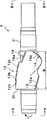
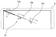
- FIG. 2 It is a front sectional view of a batch type kneader provided with a kneading rotor concerning one embodiment of the present invention. It is a front view of the kneading rotor shown in FIG. It is the arrow line view which looked at the kneading rotor shown in FIG. 2 in the A direction. It is the arrow line view seen in the B direction of the kneading rotor shown in FIG. FIG. 2 is a development view around the axis of a rotor portion of the kneading rotor shown in FIG. 1. It is an enlarged view of the C section of FIG.
- a closed batch kneader (also referred to as a closed kneader) 1 according to an embodiment of the present invention will be described with reference to FIG.
- a batch kneader 1 of this embodiment includes a chamber 3 having a kneading chamber 2, a pair of left and right kneading rotors 4, 5, a material supply cylinder 7 with a hopper 6, and a floating weight 8. And a pneumatic cylinder 9, a piston 10, a piston rod 11, a drop door 12, and a rotary actuator.
- the kneading chamber 2 has a vertical cross section (cross section orthogonal to the longitudinal direction) and has a bowl-shaped cross section. That is, the kneading chamber 2 is formed in a shape in which a pair of left and right kneading spaces having a substantially circular cross section are joined so as to overlap each other in a part in the radial direction.
- Each of the kneading rotors 4 and 5 is inserted into a corresponding kneading space of the kneading chamber 2.
- the kneading rotors 4 and 5 are provided so as to be rotatable around their respective axes in the corresponding kneading space.
- an opening for communicating the kneading chamber 2 with the outside of the chamber 3 is formed in the upper portion of the chamber 3.
- the material supply cylinder 7 is attached to the opening of the chamber 3 and is erected on the chamber 3.
- the floating weight 8 is provided in the material supply cylinder 7 so as to be movable up and down.
- the pneumatic cylinder 9 is coupled to the upper part of the material supply cylinder 7.
- the piston 10 is provided in the pneumatic cylinder 9 so as to be movable up and down.
- the piston rod 11 extends vertically through the lower lid of the cylinder 9.
- the part where the piston rod 11 penetrates the lower lid of the cylinder 9 is configured so that the inside of the cylinder 9 is kept airtight.
- the piston 10 and the floating weight 8 are connected via the piston rod 11. For this reason, when the space located above the piston 10 in the pneumatic cylinder 9 is pressurized, the piston 10, the piston rod 11, and the floating weight 8 are integrally lowered.
- the material to be kneaded supplied into the material supply cylinder 7 through the hopper 6 can be pushed into the chamber 3 (inside the kneading chamber 2) by the descending floating weight 8.
- a discharge port is provided at the bottom of the chamber 3.
- the drop door 12 is provided at the bottom of the chamber 3 and can open and close the discharge port.
- the drop door 12 is driven by a rotary actuator to open and close the discharge port.
- the drop door 12 that has closed the discharge port is driven to open the discharge port, so that the kneaded material (kneaded material) kneaded in the kneading chamber 2 for a predetermined time is discharged from the machine through the discharge port.
- the batch-type kneader 1 of this embodiment is a non-meshing kneader in which the pair of left and right kneading rotors 4 and 5 do not mesh with each other.
- the kneading rotors 4 and 5 are arranged at a predetermined interval in the width direction of the chamber 3 (left and right direction in FIG. 1).
- the kneading rotors 4 and 5 rotate in different directions so that portions facing each other in the width direction of the chamber 3 move downward.
- the kneading rotors 4 and 5 are each provided with a rotor portion 20 and a shaft portion 21 that are integrally provided.
- the rotor portion 20 is disposed at an intermediate portion in the axial direction of the kneading rotor 4.
- the shaft portion 21 extends from both ends of the rotor portion 20 in the axial direction, and is disposed coaxially with the rotor portion 20.
- the kneading machine 1 is provided with a drive source (not shown), and the kneading rotors 4 and 5 are rotated about their respective axes when a driving force is supplied from the drive source to the shaft
- the rotor unit 20 has a plurality of kneading blades 13 to 16 on the outer peripheral surface.
- the rotor unit 20 is disposed in the kneading space so that a gap (chip clearance) is formed between the tops of the kneading blades 13 to 16 and the inner surface of the chamber 3 forming the kneading space of the kneading chamber 2.
- the rotor unit 20 applies a shearing force to the material to be kneaded that passes through the chip clearance with the kneading blades 13 to 16 as the shaft rotates.
- the plurality of kneading blades 13 to 16 are spirally twisted with respect to the axis of the rotor portion 20.
- the material to be kneaded is pushed in the axial direction of the rotor unit 20 by the kneading blades 13 to 16 due to the twisting of the kneading blades 13 to 16 as described above.
- the material to be kneaded flows in the axial direction of the rotor portion 20.
- the tip clearance is a gap between the top portions (tip portions) 13a to 16a that are the tip surfaces of the kneading blades 13 to 16 and the inner surface of the chamber 3 that forms the corresponding kneading space of the kneading chamber 2.
- the tip clearance is the narrowest portion of the gap.
- the kneading blades 13 to 16 of the kneading rotors 4 and 5 have the center point in the developed shape when the rotor portions 20 of the kneading rotors 4 and 5 are developed in a planar state around the axis. They are arranged so as to be point-symmetric with respect to O.
- one kneading rotor 4 will be described as a representative of the kneading rotors 4 and 5.
- the kneading rotor 4 includes four kneading blades 13 to 16 in the rotor portion 20 thereof.
- the four kneading blades 13 to 16 have the first long blade 13 and the second long blade 13 formed so as to have a length larger than half the length W of the rotor portion 20 in the axial direction Z of the rotor portion 20. From the long blade 14 and the first short blade 15 and the second short blade 16 formed so as to have a length smaller than half the length W of the rotor portion 20 in the axial direction Z of the rotor portion 20. Become.
- the length in the axial direction Z of the rotor portion 20 of the first long blade 13, the second long blade 14, the first short blade 15, and the second short blade 16 is relative to the length W of the rotor portion 20. 0.7W, 0.65W, 0.35W and 0.3W.
- the first long blade 13 extends from one end in the axial direction Z of the rotor portion 20, where the blade is formed in the kneading rotor 4, toward the center side in the axial direction Z of the rotor portion 20. Further, the first long blade 13 is a linear blade having a linear developed shape in the developed shape of the rotor unit 20 when the rotor unit 20 of the kneading rotor 4 is developed in a planar state around the axis.
- the first long blade 13 was twisted at a twist angle of 22 degrees in a direction in which the material to be kneaded can flow to the center side of the axial direction Z of the rotor portion 20 as the rotor portion 20 rotates about the axis. It is formed in a spiral shape.
- the top portion of the first long blade 13 is formed so as to increase in three steps in order from one end side in the axial direction Z of the rotor portion 20 toward the central side in the axial direction Z of the rotor portion 20.
- the top portion of the first long blade 13 is divided into a lower tip portion 13a, a middle tip portion 13b higher than the lower tip portion 13a, and a higher tip portion 13c higher than the middle tip portion 13b. It is divided.
- the low-order tip portion 13a, the middle-order tip portion 13b, and the high-order tip portion 13c are arranged in this order from one end side in the axial direction Z of the rotor portion 20 to the central side in the axial direction Z of the rotor portion 20.
- a clearance L, a medium tip clearance M smaller than the large chip clearance L, and a small chip clearance S smaller than the medium chip clearance M are formed in order, and the large chip clearance L, medium chip clearance M, and small chip are formed.
- the clearance S is arranged so as to be aligned in the longitudinal direction of the first long blade 13. That is, three different levels of tip clearance are formed in the longitudinal direction of the first long blade 13 between the top of the first long blade 13 and the inner surface of the facing chamber 3.
- the large tip clearance L is formed between the lower tip portion 13a and the inner surface of the chamber 3 facing the lower tip portion 13a.
- the middle tip clearance M is formed between the middle tip portion 13b and the inner surface of the chamber 3 facing the middle tip portion 13b.
- the small tip clearance S is formed between the high-order tip portion 13c and the inner surface of the chamber 3 facing the high tip portion 13c.
- the large tip clearance L is a tip clearance whose ratio to the inner diameter of the kneading space of the kneading chamber 2 is in the range of 0.0250 to 0.1000, and the middle chip clearance M is 0.0100 to 0.00.
- the tip clearance is in the range of 0500, and the small tip clearance S is the tip clearance in the range of 0.0025 to 0.0250.
- the flow of the material to be kneaded around the first long blade 13 is indicated by an arrow in the circumferential direction of the rotor portion 20 by setting the top portion of the first long blade 13 to three different heights.
- the distribution amount (flow rate) of the material to be kneaded and the flow rate of the material to be kneaded in the axial direction Z of the rotor portion 20 vary in each of the tip portions 13a to 13c.
- the flow of the material to be kneaded in the kneading chamber 2 becomes complicated. Thereby, kneading
- the high-order tip portion 13c forming the small tip clearance S on the center side in the axial direction Z of the rotor portion 20, it is possible to ensure the shearing force applied to the material to be kneaded and the rotor portion 20.
- the flow of the same material in the axial direction Z can be ensured.
- the middle tip portion 13b and the lower tip portion 13a disposed on one end side in the axial direction Z of the rotor portion 20 with respect to the higher-order tip portion 13c form the middle tip clearance M and the large tip clearance L, these tips are formed.
- the parts 13b and 13c apply a relatively small shearing force to the material to be kneaded.
- the kneading rotor 4 can be rotated at a high speed, and as a result, a strong flow of the material to be kneaded in the kneading chamber 2 (circumferential direction and axial flow of the rotor portion 20) is ensured.
- the shearing force applied to the material to be kneaded it is possible to ensure the shearing force applied to the material to be kneaded and improve the distribution performance (kneading performance) of the material to be kneaded.
- the flow rate of the material to be kneaded in the circumferential direction of the rotor portion 20 is large, while the longitudinal direction of the first long blade 13 or the axial direction of the rotor portion 20.
- the flow rate of the material to be kneaded to Z becomes small.
- the middle tip clearance M formed by the middle tip portion 13b the flow rate of the material to be kneaded in the circumferential direction of the rotor portion 20 is medium, while the longitudinal direction of the first long blade 13 or the axis of the rotor portion 20 is set.
- the flow rate of the material to be kneaded in the direction Z is medium.
- the flow rate of the material to be kneaded in the circumferential direction of the rotor portion 20 is small, while the longitudinal direction of the first long blade 13 or the axial direction of the rotor portion 20
- the flow rate of the material to be kneaded to Z increases.
- each of the chip portions 13a to 13c is formed at a certain height over the entire length thereof. That is, the top of the first long blade 13 is composed of each tip portion (each land portion) formed horizontally in the longitudinal direction of the first long blade 13. In other words, the top of the first long blade 13 is formed in a three-stage step shape that is horizontal in the longitudinal direction of the first long blade 13. From the viewpoint of sufficiently promoting the kneading of the material to be kneaded, it is preferable to form the first long blades 13 in a stepped manner as in the present embodiment, but this is not always necessary.
- the top of the first long blade may be formed in a shape in which each tip portion (each land portion) is inclined with respect to the longitudinal direction of the first long blade or the rotation direction of the first long blade. .
- the first short blade 15 extends from one end in the axial direction Z of the rotor part 20 toward the center side in the axial direction Z of the rotor part 20.
- the first short blade 15 is a linear blade having a linear developed shape in the developed shape of the rotor portion 20. Then, the first short blade 15 was twisted at a twist angle of 22 degrees in the direction in which the material to be kneaded can flow to the center side in the axial direction Z of the rotor portion 20 as the rotor portion 20 rotates about the axis. It is formed in a spiral shape.
- the top 15a of the first short blade 15 is formed to have a certain height.
- the tip clearance formed between the top 15a of the first short blade 15 and the inner surface of the facing chamber 3 has a size corresponding to the middle tip clearance M.
- the length (0.35 W) of the first short blade 15 in the axial direction Z of the rotor portion 20 is larger than the length of the lower tip portion 13a of the first long blade 13 in the same direction Z.
- the material to be kneaded distributed in the circumferential direction of the rotor portion 20 by the portion of the first long blade 13 located near one end in the axial direction Z of the rotor portion 20 is formed by the top portion 15a of the first short blade 15. It is possible to prevent a short path from being simply passed in the circumferential direction of the rotor portion 20 through the tip clearance.
- the first short blade 13 is applied to the material to be kneaded distributed in the circumferential direction of the rotor portion 20 by the portion of the first long blade 13 located near one end in the axial direction Z of the rotor portion 20. 15 can effectively apply a shearing force. As a result, the kneading performance of the kneading rotor 4 is improved.
- the second long blade 14 extends from the other end of the rotor portion 20 in the axial direction Z toward the center side of the rotor portion 20 in the axial direction Z. Further, the second long blade 14 is deployed such that the twist angle gradually decreases from the other end side in the axial direction Z of the rotor portion 20 toward the center side in the axial direction Z of the rotor portion 20 in the deployed shape of the rotor portion 20.
- a non-linear wing having a shape is formed.
- the inclination angle of the portion of the second long blade 14 located on the other end side in the axial direction Z of the rotor portion 20 is the inclination of the virtual straight line HL connecting the start point P and the end point Q of the second long blade 14.
- the inclination angle of the portion of the second long blade 14 located on the center side in the axial direction Z of the rotor portion 20 is smaller than the inclination angle of the virtual straight line HL.
- the second long blade 14 is formed in a spiral shape twisted in a direction in which the material to be kneaded can flow to the center side in the axial direction Z of the rotor portion 20 as the rotor portion 20 rotates about the axis. Yes.
- the second long blade 14 is twisted in the opposite direction to the first long blade 13. Moreover, the edge part located in the center side of the axial direction Z of the rotor part 20 among the 1st short blades 15 and the edge part located in the other end side of the axial direction Z of the rotor part 20 among the 2nd long blades 14
- the phase difference b is 121.5 degrees (about 122 degrees).
- the twist angle at the end portion of the second long blade 14 located on the other end side in the axial direction Z of the rotor portion 20 is about 60 degrees.
- the material to be kneaded hardly flows, but the twist angle of the second long blade 14 at the other end of the rotor portion 20 is about By being 60 degrees, distribution (flow) in the circumferential direction of the material to be kneaded around the other end of the rotor portion 20 can be promoted.
- twist angle of the second long blade 14 at the other end of the rotor portion 20 is set to 45 degrees or more, distribution (flow) of the material to be kneaded in the circumferential direction can be promoted.
- the twist angle of the portion of the second long blade 14 located on the center side in the axial direction Z of the rotor portion 20 is the portion of the second long blade 14 located on the other end side in the axial direction Z of the rotor portion 20.
- the flow rate of the material to be kneaded in the circumferential direction around the center in the axial direction Z of the rotor portion 20 is smaller than around the other end in the axial direction Z of the rotor portion 20. Less.
- the shearing force applied to the material to be kneaded is increased near the center of the rotor portion 20 and the flow of the material to be kneaded in the axial direction Z of the rotor portion 20 is promoted.
- the top 14a of the second long blade 14 is formed to have a certain height.
- the tip clearance formed between the top portion 14a of the second long blade 14 and the inner surface of the facing chamber 3 has a size corresponding to the middle tip clearance M.
- the second short blade 16 extends from the other end of the rotor portion 20 in the axial direction Z toward the center side of the rotor portion 20 in the axial direction Z.
- the second short blade 16 is a linear blade having a linear developed shape in the developed shape of the rotor portion 20. Then, the second short blade 16 was twisted at a twist angle of 22 degrees in a direction in which the material to be kneaded can flow to the center side in the axial direction Z of the rotor portion 20 as the rotor portion 20 rotates about the axis. It is formed in a spiral shape. That is, the second short blade 16 is twisted in the opposite direction to the first short blade 15.
- top portion 16a of the second short blade 16 is formed to have a certain height.
- the tip clearance formed between the top portion 16a of the second short blade 16 and the inner surface of the facing chamber 3 has a size corresponding to the medium tip clearance M.
- the floating weight 8 is separated from the chamber 3 while the drop door 12 is in close contact with the chamber 3, thereby opening the upper opening of the chamber 3. Then, a material to be kneaded in which silica and a silane coupling agent are mixed with rubber is loaded into the chamber 3 (in the kneading chamber 2) from the material supply cylinder 7 through the opening, and then the floating weight 8 is brought into close contact with the chamber 3. Thus, the material to be kneaded is sealed in the chamber 3 (in the kneading chamber 2) under pressure.
- kneading of the materials to be kneaded is started by rotating the kneading rotors 4 and 5 in opposite directions.
- the kneading blades 13 to 16 of the rotor portions 20 of both the kneading rotors 4 and 5 disperse the material to be kneaded while applying a shearing force to the material to be kneaded to knead the material.
- the drop door 12 is separated from the chamber 3 and the discharge port at the bottom of the chamber 3 is opened, and the kneaded material (kneaded material) is taken out of the machine through the discharge port. Discharge.
- Table 7 is a graph showing the kneading results of the kneading rotors 4 and 5 of this embodiment and the kneading rotor according to the comparative example.
- Table 1 shows the contents of the materials to be kneaded used in the experiment.
- S-SBR is a solution-polymerized styrene butadiene rubber.
- BR is butadiene rubber.
- a kneading rotor (batch type kneader) used as a comparative example is a kneading rotor described in Japanese Patent No. 3980841 (Japanese Patent No. 3980841) having one nonlinear blade and three linear blades as kneading blades. 4) (Batch type kneader (1)). In FIG.
- the solid line indicates the kneading result when the kneading rotors 4 and 5 of the present embodiment are used, and the dotted line indicates the kneading result when the kneading rotor of the comparative example is used.
- the ⁇ G ′ value is taken on the vertical axis of the graph, and the temperature (discharge temperature) of the kneaded material discharged from the discharge port of the chamber is taken on the horizontal axis of the graph.
- the tip portions of the first long blades 13 are arranged so that the tip clearances L, M, and S having different sizes in three stages are arranged in the longitudinal direction of the first long blades 13.
- the top portions of the other three kneading blades 14 to 16 form a tip clearance of a size corresponding to the middle tip clearance M formed by the middle tip portion 13b of the top portions of the first long blades 13. .
- FIG. 7 when the material to be kneaded is kneaded in a high temperature state, a kneaded material with better quality than before can be obtained.
- the lower tip portion 13 a located on one end side in the axial direction Z of the rotor portion 20 among the top portions of the first long blades 13 has a large tip clearance L larger than the small tip clearance S in the rotor portion 20. It is formed at a position closest to one end in the axial direction Z. Accordingly, in the kneading space of the kneading chamber 2, the distribution (flow) of the material to be kneaded in the circumferential direction is promoted in the region where the material to be kneaded is difficult to flow around the end in the axial direction Z of the rotor portion 20. can do.
- the tip portion located on one end side in the axial direction Z of the rotor portion 20 in the top portion of the first long blade 13 may be a middle tip portion 13b that forms a middle tip clearance M.
- the high-order tip portion 13 c located on the center side in the axial direction Z of the rotor portion 20 among the top portions of the first long blades 13 has a small tip clearance S smaller than the large tip clearance L in the rotor portion 20. It is formed at a position closest to the center in the axial direction Z. Thereby, in the area
- the second long blade 14 that is arranged behind the high-order tip portion 13c in the rotation direction r of the rotor portion 20 and extends from the other end side in the axial direction Z of the rotor portion 20 toward the center side is used extensively.
- a shear force can be effectively applied to the material to be kneaded whose flow is promoted to the other end side of the rotor portion 20 by the high-order tip portion 13c.
- the tip part located in the center side of the axial direction Z of the rotor part 20 among the top parts of the 1st long blade 13 may be the middle tip part 13b which forms the middle tip clearance M.
- a more desirable form is the first so that the tip clearances are formed in the order of the tip clearances L, M, and S from the one end side in the axial direction Z of the rotor portion 20 toward the center as in this embodiment.
- the top of the long wing 13 is formed.
- the high-order tip portion or the high-order tip portion and the middle tip portion are located near the central portion in the axial direction Z of the rotor portion 20, and as a result, in the kneading chamber 2.
- the additional effect that the biting by the rotor part 20 of the material to be kneaded soon after being press-fitted can be promoted is obtained.
- the second long blade 14 is formed as a non-linear blade whose twist angle gradually decreases from the other end side in the axial direction Z of the rotor portion 20 toward the center side in the axial direction Z of the rotor portion 20. Therefore, the distribution of the material to be kneaded in the circumferential direction of the rotor portion 20 is promoted toward the center side in the axial direction Z of the rotor portion 20.
- the first long blade 13, the first short blade 15, and the second short blade 16 distribute the material in the circumferential direction of the rotor portion 20 and the material in the axial direction Z of the rotor portion 20. It is formed to have a twist angle of 22 degrees with a good balance with the flow.
- the top part of the first long blade 13 has three different sizes in the order of tip clearances L, M, and S from one end side in the axial direction Z of the rotor part 20 toward the central side in the axial direction Z of the rotor part 20.
- the order of the tip clearance formed by the top of the first long blade 13 is not limited to this.
- the top portion of the first long blade 13 is arranged in the order of the tip clearances L, S, M from the one end side in the axial direction Z of the rotor portion 20 toward the center side in the axial direction Z of the rotor portion 20 or the tip clearance.
- Tip clearances may be formed in the order of M, L, and S.
- the tip clearance formed first (first) from one end side in the axial direction Z of the rotor portion 20 is the tip clearance formed third from the one end side in the axial direction Z of the rotor portion 20 (the axis of the rotor portion 20 It is important that a three-stage chip clearance is formed so as to be smaller than the chip clearance formed at the most central side in the direction Z).
- the top of at least one kneading blade among the kneading blades 14 to 16 other than the first long blade 13 is formed in a shape that forms a multi-step chip clearance with the inner surface of the facing chamber 3. Also good. Thereby, the flow of the material to be kneaded in the kneading chamber can be further complicated.
- the second long wing 14 may be a linear wing. Further, the second long blade 14 may be a non-linearly formed long blade, and the top portion thereof may be formed in a shape that forms a three-stage tip clearance.
- the tip clearance formed by the tops of the three kneading blades 14 to 16 may be larger than the small tip clearance S formed by the tops of the first long blades 13 and less than the large tip clearance L. . If the top portions of the kneading blades 14 to 16 are formed so as to form a tip clearance larger than the large tip clearance L, the amount of short path of the material to be kneaded in the circumferential direction of the rotor portion 20 becomes too large. An appropriate shear force cannot be applied to the material.
- the top portions of the kneading blades 14 to 16 are formed so as to form a chip clearance smaller than the small chip clearance S, the dispersibility of the material to be kneaded deteriorates, and as a result, the material to be kneaded is kneaded at a high temperature. In addition, it becomes impossible to obtain a kneaded product of good quality.
- the twist angle of the three kneading blades 13, 15, 16 excluding the second long blade 14 is set to 22 degrees.
- the twist angle may be an angle within the range of 15 degrees to 35 degrees. That's fine. If comprised in this way, the balance with the distribution of the to-be-kneaded material to the circumferential direction of the rotor part 20 and the flow of the same material to the axial direction Z of the rotor part 20 can be ensured.
- the non-meshing type (tangential type) kneading rotor (kneading machine) is exemplified, but the present invention can also be applied to a uniaxial kneading rotor (kneading machine).
- the kneading rotor is a kneading rotor that is rotatably inserted in a kneading chamber of a chamber of a batch type kneader, and has a plurality of kneading blades on the outer peripheral surface, and the top of the kneading blades And a rotor that is arranged in the kneading chamber so that a chip clearance is formed between the inner surface of the chamber forming the kneading chamber and applies a shearing force to the material to be kneaded that passes through the chip clearance by the kneading blades
- the plurality of kneading blades have a length that is greater than half the length of the rotor portion in the axial direction of the rotor portion, and are kneaded as the rotor portion rotates about the axis.
- the first short blade is disposed behind the first long blade in the rotational direction of the rotor portion, and the rotor portion is in a planar state around the axis.
- the first long wing is a large wing.
- the chip forming the kneading chamber has three different sizes of chip clearance comprising a combination of a pre-clearance, a medium chip clearance smaller than the large chip clearance, and a small chip clearance smaller than the medium chip clearance.
- the top of one long blade (first long blade) is formed so that tip clearances of three different sizes are arranged in the longitudinal direction of the long blade, and the tops of the other kneading blades are Since the tip clearance having a size larger than the small tip clearance formed by the top of the long blade and smaller than the large tip clearance is formed, a shearing force equivalent to that of the prior art is applied to the material to be kneaded, while being subjected to the covering in the kneading chamber.
- the flow of the kneaded material can be complicated. That is, in this configuration, distribution of the material can be promoted while applying a shearing force similar to that of the conventional technology to the material to be kneaded.
- the top portion of the kneading blade is a tip portion (also referred to as a land portion) formed on the surface of the kneading blade that faces the inner surface of the chamber forming the kneading chamber.
- the tip clearance is a gap between the tip portion (the top of the kneading blade) and the inner surface of the chamber forming the kneading chamber.
- the top of the first long blade has a tip clearance larger than the small tip clearance among the three stages of tip clearance formed at a position closest to one end in the axial direction of the rotor portion. Is preferred.
- the material to be kneaded does not flow easily in a region around the axial end of the rotor portion, but according to this configuration, the distribution (flow) of the material to be kneaded in the circumferential direction is promoted in that region. be able to. For this reason, it is possible to prevent a part of the material to be kneaded from excessively rising in temperature and deteriorating its quality.
- the top portion of the first long blade is formed with a tip clearance smaller than the large tip clearance among the three-stage tip clearances at a position closest to the axial center of the rotor portion. Is preferred.
- the flow of the material to be kneaded to the other end side in the axial direction of the rotor portion can be ensured around the portion of the first long blade closest to the center in the axial direction of the rotor portion.
- the second long blades arranged apart from the first long blades in the circumferential direction of the rotor portion are used extensively to effectively apply shear force to the material to be kneaded whose flow is promoted by the first long blades. be able to.
- the top of the first long blades extends from one end side in the axial direction of the rotor portion toward the center side in the axial direction of the rotor portion, and the large tip clearance, the medium tip clearance, It is preferable to form the tip clearance in the order of the small tip clearance.
- the second long blade is formed such that a twist angle at an end portion of the second long blade located on the other end side in the axial direction of the rotor portion is 45 degrees or more. It is preferable.
- the distribution (flow) of the material to be kneaded in the circumferential direction can be promoted in the region of the kneading chamber around the axial end of the rotor portion where the material to be kneaded is difficult to flow. it can. For this reason, it is possible to prevent a part of the material to be kneaded from excessively rising in temperature and deteriorating its quality.
- the length of the first short blade in the axial direction of the rotor portion is one end in the axial direction of the rotor portion in the tip clearance of the three stages of the top portion of the first long blade.
- the portion of the rotor portion that is located closest to the tip clearance is longer than the length of the rotor portion in the axial direction, and the top portion of the first short blade is one end in the axial direction of the rotor portion by the first long blade. It is preferable to form a tip clearance having a size equal to or smaller than the tip clearance formed closest to the inner surface of the chamber.
- the material to be kneaded distributed in the circumferential direction of the rotor portion by the portion located in the vicinity of one end in the axial direction of the rotor portion of the first long blade is the tip clearance formed by the top of the first short blade.
- the first short blade effectively applies a shear force to the material to be kneaded distributed in the circumferential direction of the rotor portion by the portion of the first long blade located near one end in the axial direction of the rotor portion. Can be given.
- the kneading effect of the material to be kneaded can be improved.
- the twist angle of the second long blade gradually decreases from the other end side in the axial direction of the rotor portion toward the central side in the axial direction of the rotor portion in the developed shape of the rotor portion.
- the first long wing, the first short wing, and the second short wing are formed so as to have a twist angle of 15 degrees or more and 35 degrees or less, respectively. Preferably it is.
- the distribution of the material to be kneaded in the circumferential direction of the rotor portion can be promoted by using the second long blade.
- the temperature range of the material that can be kneaded can be expanded from the low temperature range where kneading has conventionally been possible to the high temperature range where it has been difficult to sufficiently knead, and the kneaded material after kneading can be expanded in the wide temperature range of the material. Quality can be improved.
- the top of at least one kneading blade among the second long blade, the first short blade, and the second short blade has the large tip clearance, the medium tip clearance, and the small tip clearance. It is preferable to form chip clearances of different sizes including a plurality of stages so as to be aligned in the longitudinal direction of the kneading blade.
- the batch-type kneader according to the embodiment is a non-engagement-type batch-type kneader provided with a pair of kneading rotors having any one of the above-described configurations and arranged so that the two kneading rotors do not mesh with each other.
- a kneaded material with better quality than before can be obtained when the material to be kneaded is kneaded at a high temperature.
- the material kneading method according to the above embodiment is to knead the material to be kneaded containing silica and the silane coupling agent by the batch kneader.
- the quality of the kneaded material obtained by kneading the material to be kneaded to which a large amount of silica is added (blended) can be improved as compared with the conventional one.
Landscapes
- Engineering & Computer Science (AREA)
- Mechanical Engineering (AREA)
- Chemical & Material Sciences (AREA)
- Chemical Kinetics & Catalysis (AREA)
- Processing And Handling Of Plastics And Other Materials For Molding In General (AREA)
- Mixers Of The Rotary Stirring Type (AREA)
Abstract
Description
図1を参照しつつ本発明の一実施形態に係る密閉式のバッチ式混練機(密閉型混練機とも称される)1について説明する。図1に示すように、本実施形態のバッチ式混練機1は、混練室2を有するチャンバ3と、左右一対の混練ロータ4,5と、ホッパ6付きの材料供給筒7と、フローティングウェイト8と、空圧シリンダ9と、ピストン10と、ピストンロッド11と、ドロップドア12と、ロータリーアクチュエータとを備えている。
次に、図1~図6を参照して、混練ロータ4,5の構成について説明する。
第一長翼13は、混練ロータ4において翼が形成される部分であるロータ部20の軸方向Zの一端からロータ部20の軸方向Zの中央側へ向かって延びている。また、第一長翼13は、混練ロータ4のロータ部20を軸心回りに平面状態に展開した場合にそのロータ部20の展開形状において線形の展開形状を有する線形翼である。そして、第一長翼13は、ロータ部20の軸回りの回転に伴って被混練材料をロータ部20の軸方向Zの中央側へ流すことが可能な方向に22度の捩れ角度で捩れた螺旋状に形成されている。
第一短翼15は、ロータ部20の軸方向Zの一端からロータ部20の軸方向Zの中央側へ向かって延びている。また、第一短翼15は、前記ロータ部20の展開形状において線形の展開形状を有する線形翼である。そして、第一短翼15は、ロータ部20の軸回りの回転に伴って被混練材料をロータ部20の軸方向Zの中央側へ流すことが可能な方向に22度の捩れ角度で捩れた螺旋状に形成されている。また、第一短翼15は、ロータ部20の回転方向rにおいて第一長翼13の後方に配置されている。具体的には、第一短翼15は、ロータ部20の軸方向Zの一端において第一長翼13に対して位相差a=117度だけずらして形成されている。
第二長翼14は、ロータ部20の軸方向Zの他端からロータ部20の軸方向Zの中央側へ向かって延びている。また、第二長翼14は、前記ロータ部20の展開形状においてロータ部20の軸方向Zの他端側からロータ部20の軸方向Zの中央側へ向かうにつれて捩れ角度が漸減するような展開形状を有する非線形翼に形成されている。すなわち、第二長翼14のうちロータ部20の軸方向Zの他端側に位置する部分の傾斜角度は、当該第二長翼14の始点Pと終点Qとを結んだ仮想直線HLの傾斜角度よりも大きくなっている一方、第二長翼14のうちロータ部20の軸方向Zの中央側に位置する部分の傾斜角度は、仮想直線HLの傾斜角度よりも小さくなっている。また、第二長翼14は、ロータ部20の軸回りの回転に伴って被混練材料をロータ部20の軸方向Zの中央側へ流すことが可能な方向に捩れた螺旋状に形成されている。すなわち、第二長翼14は、第一長翼13とは逆方向に捩れている。また、第一短翼15のうちロータ部20の軸方向Zの中央側に位置する端部と、第二長翼14のうちロータ部20の軸方向Zの他端側に位置する端部との間の位相差bは、121.5度(約122度)である。
第二短翼16は、ロータ部20の軸方向Zの他端からロータ部20の軸方向Zの中央側へ向かって延びている。また、第二短翼16は、前記ロータ部20の展開形状において線形の展開形状を有する線形翼である。そして、第二短翼16は、ロータ部20の軸回りの回転に伴って被混練材料をロータ部20の軸方向Zの中央側へ流すことが可能な方向に22度の捩れ角度で捩れた螺旋状に形成されている。すなわち、第二短翼16は、第一短翼15とは逆方向に捩れている。また、第二短翼16は、ロータ部20の回転方向rにおいて第二長翼14の後方に配置されている。具体的には、第二短翼16は、ロータ部20の軸方向Zの他端において第二長翼14に対して位相差c=169.5度(約170度)だけずらして形成されている。
図1を参照しつつ、バッチ式混練機1の動作について説明する。まず、チャンバ3にドロップドア12を密接させた状態でフローティングウェイト8をチャンバ3から離隔させることによって、チャンバ3の上部の開口部を開放する。そして、ゴムにシリカおよびシランカップリング剤などを配合した被混練材料を材料供給筒7から前記開口部を通じてチャンバ3内(混練室2内)に装填した後、フローティングウエイト8をチャンバ3に密接させることによって被混練材料をチャンバ3内(混練室2内)に圧力を掛けて封入する。
次に、前記混練ロータ4,5を備えたバッチ式混練機1と比較例の混練ロータを備えたバッチ式混練機とを同じ条件で動作させて両者の性能の差を調査する実験を行った。この実験では、シリカをPHR80となるように配合した被混練材料を用いた。ここで、PHR(Parts per Hundred Rubber)とは、ゴムの重量100に対する各種配合剤の重量部のことをいう。図7は、本実施形態の混練ロータ4,5と比較例に係る混練ロータとによる混練結果を示すグラフである。表1に、実験で用いた被混練材料の配合内容を示す。

前記実施形態をまとめると、以下の通りである。
Claims (10)
- バッチ式混練機のチャンバが有する混練室内に回転自在に挿通された混練ロータであって、
複数の混練翼を外周面に有し、その混練翼の頂部と前記混練室を形成する前記チャンバの内面との間にチップクリアランスが形成されるように前記混練室内に配置され、前記チップクリアランスを通過する被混練材料に前記混練翼により剪断力を付与するロータ部を備え、
前記複数の混練翼は、前記ロータ部の軸方向においてそのロータ部の長さの半分の長さよりも大きな長さを有し、前記ロータ部の軸回りの回転に伴って被混練材料を前記ロータ部の軸方向の中央側へ流すことが可能な方向で且つ互いに逆方向に捩れた第一長翼および第二長翼と、前記ロータ部の軸方向においてそのロータ部の長さの半分の長さよりも小さな長さを有し、前記ロータ部の軸回りの回転に伴って被混練材料を前記ロータ部の軸方向の中央側へ流すことが可能な方向で且つ互いに逆方向に捩れた第一短翼および第二短翼とを含み、
前記第一短翼は、前記ロータ部の回転方向において前記第一長翼の後方に配置され、前記ロータ部を軸心回りに平面状態に展開した場合にそのロータ部の展開形状において当該ロータ部の軸方向の一端側から当該ロータ部の軸方向の中央側へ延びる展開形状を有する線形翼であり、
前記第二短翼は、前記ロータ部の回転方向において前記第二長翼の後方に配置され、前記ロータ部の展開形状において前記ロータ部の軸方向の他端側から前記ロータ部の軸方向の中央側へ延びる展開形状を有する線形翼であり、
前記第一長翼は、大チップクリアランスと、その大チップクリアランスよりも小さい中チップクリアランスと、その中チップクリアランスよりも小さい小チップクリアランスとの組合せからなる3段階の異なる大きさのチップクリアランスを前記混練室を形成する前記チャンバの内面との間で当該第一長翼の長手方向に並ぶように形成する頂部を有し、
前記第二長翼、前記第一短翼および前記第二短翼は、前記混練室を形成する前記チャンバの内面との間で前記小チップクリアランス以上で前記大チップクリアランス以下の大きさのチップクリアランスを形成する頂部をそれぞれ有する、混練ロータ。 - 請求項1に記載の混練ロータにおいて、
前記第一長翼の頂部は、前記3段階のチップクリアランスのうち前記小チップクリアランスよりも大きいチップクリアランスを前記ロータ部の軸方向の一端から最も近い位置に形成する、混練ロータ。 - 請求項1に記載の混練ロータにおいて、
前記第一長翼の頂部は、前記3段階のチップクリアランスのうち前記大チップクリアランスよりも小さいチップクリアランスを前記ロータ部の軸方向の中央から最も近い位置に形成する、混練ロータ。 - 請求項1に記載の混練ロータにおいて、
前記第一長翼の頂部は、前記ロータ部の軸方向の一端側から前記ロータ部の軸方向の中央側へ向かって、前記大チップクリアランス、前記中チップクリアランス、前記小チップクリアランスの順でチップクリアランスを形成する、混練ロータ。 - 請求項1に記載の混練ロータにおいて、
前記第二長翼は、前記ロータ部の軸方向の他端側に位置する当該第二長翼の端部における捩れ角度が45度以上となるように形成されている、混練ロータ。 - 請求項1に記載の混練ロータにおいて、
前記ロータ部の軸方向における前記第一短翼の長さは、前記第一長翼の頂部のうち前記3段階のチップクリアランスの中で前記ロータ部の軸方向の一端の最も近くに位置するチップクリアランスを形成する部分の前記ロータ部の軸方向についての長さ以上であり、
前記第一短翼の頂部は、前記第一長翼によって前記ロータ部の軸方向の一端の最も近くに形成されたチップクリアランス以下の大きさのチップクリアランスを前記チャンバの内面との間で形成する、混練ロータ。 - 請求項1に記載の混練ロータにおいて、
前記第二長翼は、前記ロータ部の展開形状において、当該ロータ部の軸方向の他端側から当該ロータ部の軸方向の中央側へ向かうにつれて捩れ角度が漸減するような展開形状を有する非線形翼に形成されており、
前記第一長翼、前記第一短翼および前記第二短翼は、捩れ角度が15度以上35度以下となるようにそれぞれ形成されている、混練ロータ。 - 請求項1に記載の混練ロータにおいて、
前記第二長翼、前記第一短翼および前記第二短翼のうち少なくとも1つの混練翼の頂部は、前記大チップクリアランス、前記中チップクリアランスおよび前記小チップクリアランスを含む複数段階の異なる大きさのチップクリアランスをその混練翼の長手方向に並ぶように形成する、混練ロータ。 - 請求項1~8のいずれか1項に記載の混練ロータを一対備え、それら両混練ロータが互いに噛み合わないように配置されている、非噛み合い型のバッチ式混練機。
- 請求項9に記載のバッチ式混練機により、シリカおよびシランカップリング剤を配合した被混練材料を混練する、材料混練方法。
Priority Applications (9)
| Application Number | Priority Date | Filing Date | Title |
|---|---|---|---|
| EP10731249.8A EP2380718B1 (en) | 2009-01-19 | 2010-01-13 | Kneading rotor, batch kneader, and material kneading method |
| CN201080004752.5A CN102282000B (zh) | 2009-01-19 | 2010-01-13 | 混合搅拌转子、分批式混合搅拌机及材料混合搅拌方法 |
| ES10731249.8T ES2455243T3 (es) | 2009-01-19 | 2010-01-13 | Rotor de amasado, amasadora discontinua, y método de amasado de material |
| KR1020117016647A KR101284421B1 (ko) | 2009-01-19 | 2010-01-13 | 혼련 로터, 뱃치식 혼련기 및 재료 혼련 방법 |
| BRPI1006009-0A BRPI1006009B1 (pt) | 2009-01-19 | 2010-01-13 | Rotor de amassamento, amassadeira em batelada e processo de amassamento de materiais |
| US13/129,038 US8926166B2 (en) | 2009-01-19 | 2010-01-13 | Kneading rotor, batch kneader and method of kneading materials |
| MX2011007659A MX2011007659A (es) | 2009-01-19 | 2010-01-13 | Rotor de amasado, amasador de tanda y metodo para amasar materiales. |
| RU2011134633/02A RU2472616C1 (ru) | 2009-01-19 | 2010-01-13 | Перемешивающий ротор, месильная машина периодического действия и способ перемешивания материалов |
| CA2742730A CA2742730C (en) | 2009-01-19 | 2010-01-13 | Kneading rotor, batch kneader and method of kneading materials |
Applications Claiming Priority (2)
| Application Number | Priority Date | Filing Date | Title |
|---|---|---|---|
| JP2009-008447 | 2009-01-19 | ||
| JP2009008447A JP4568785B2 (ja) | 2009-01-19 | 2009-01-19 | 混練ロータ |
Publications (1)
| Publication Number | Publication Date |
|---|---|
| WO2010082580A1 true WO2010082580A1 (ja) | 2010-07-22 |
Family
ID=42339834
Family Applications (1)
| Application Number | Title | Priority Date | Filing Date |
|---|---|---|---|
| PCT/JP2010/050267 Ceased WO2010082580A1 (ja) | 2009-01-19 | 2010-01-13 | 混練ロータ、バッチ式混練機および材料混練方法 |
Country Status (13)
| Country | Link |
|---|---|
| US (1) | US8926166B2 (ja) |
| EP (1) | EP2380718B1 (ja) |
| JP (1) | JP4568785B2 (ja) |
| KR (1) | KR101284421B1 (ja) |
| CN (1) | CN102282000B (ja) |
| AR (1) | AR075030A1 (ja) |
| BR (1) | BRPI1006009B1 (ja) |
| CA (1) | CA2742730C (ja) |
| ES (1) | ES2455243T3 (ja) |
| MX (1) | MX2011007659A (ja) |
| RU (1) | RU2472616C1 (ja) |
| TW (1) | TWI453104B (ja) |
| WO (1) | WO2010082580A1 (ja) |
Cited By (1)
| Publication number | Priority date | Publication date | Assignee | Title |
|---|---|---|---|---|
| JP2015039789A (ja) * | 2013-08-20 | 2015-03-02 | 株式会社神戸製鋼所 | 密閉式混練機 |
Families Citing this family (13)
| Publication number | Priority date | Publication date | Assignee | Title |
|---|---|---|---|---|
| JP4542605B1 (ja) | 2009-04-15 | 2010-09-15 | 株式会社神戸製鋼所 | 密閉式混練機及び混練ロータ |
| KR101426986B1 (ko) * | 2011-03-31 | 2014-08-06 | 코오롱인더스트리 주식회사 | 로터 및 이를 포함하는 표면 결정화장치 |
| JP5797121B2 (ja) | 2012-01-25 | 2015-10-21 | 三菱重工マシナリーテクノロジー株式会社 | 混練用ロータ、混練機、及び混練用ロータの製造方法 |
| JP5792650B2 (ja) * | 2012-01-31 | 2015-10-14 | 株式会社神戸製鋼所 | 混練ロータ、およびそれを備える密閉式混練機 |
| JP5822800B2 (ja) * | 2012-08-21 | 2015-11-24 | 株式会社神戸製鋼所 | 混練ロータ及び混練機 |
| JP6087135B2 (ja) * | 2012-12-26 | 2017-03-01 | 株式会社ブリヂストン | 混練装置 |
| JP6000177B2 (ja) | 2013-03-27 | 2016-09-28 | 株式会社神戸製鋼所 | 混練機及び混練方法 |
| JP6972534B2 (ja) * | 2016-10-31 | 2021-11-24 | 住友ゴム工業株式会社 | 混練機投入用ポリマー |
| JP6964037B2 (ja) * | 2018-04-09 | 2021-11-10 | 株式会社神戸製鋼所 | 混練ロータ |
| JP7288378B2 (ja) | 2019-10-01 | 2023-06-07 | 株式会社日本製鋼所 | 樹脂用押出機、ロータ型スクリュ及び樹脂製造方法 |
| CN113001981A (zh) * | 2021-02-23 | 2021-06-22 | 江苏威拉里新材料科技有限公司 | 一种3d打印用送料装置 |
| CN114919087A (zh) * | 2021-06-10 | 2022-08-19 | 江门市嘉伊家实业有限公司 | 一种硅胶饭盒生产用原料处理装置 |
| CN114311376A (zh) * | 2021-12-27 | 2022-04-12 | 大连橡胶塑料机械有限公司 | 一种密炼机的切线型低温转子 |
Citations (11)
| Publication number | Priority date | Publication date | Assignee | Title |
|---|---|---|---|---|
| JPH04276406A (ja) * | 1991-03-04 | 1992-10-01 | Kobe Steel Ltd | 密閉式混練機 |
| JPH08229938A (ja) * | 1995-03-01 | 1996-09-10 | Mitsubishi Heavy Ind Ltd | 密閉式ゴム混練機 |
| JPH10151334A (ja) * | 1996-11-22 | 1998-06-09 | Nippon Spindle Mfg Co Ltd | 混練装置における混練用ロータ |
| JPH1148239A (ja) * | 1996-12-19 | 1999-02-23 | Kobe Steel Ltd | 密閉型混練装置 |
| JP2004530546A (ja) | 2001-05-04 | 2004-10-07 | ファレル コーポレイション | バッチ式密閉式混合機中で改良された分散的及び分配的混合を提供する為の同調駆動用四つ羽根非かみ合いローター |
| JP2005144703A (ja) * | 2003-11-11 | 2005-06-09 | Toyoda Gosei Co Ltd | 密閉型混練機 |
| JP2005199503A (ja) * | 2004-01-14 | 2005-07-28 | Bridgestone Corp | ゴムの混練方法 |
| JP2006123272A (ja) * | 2004-10-27 | 2006-05-18 | Yokohama Rubber Co Ltd:The | 未加硫ゴムの混練方法 |
| JP2006142616A (ja) * | 2004-11-18 | 2006-06-08 | Kobe Steel Ltd | 密閉式混練機およびそれに用いられている混練ロータ |
| JP2006218691A (ja) * | 2005-02-09 | 2006-08-24 | Sumitomo Rubber Ind Ltd | ゴム混練機及びゴム混練機からのゴム排出方法 |
| JP3980841B2 (ja) | 2000-04-26 | 2007-09-26 | 住友ゴム工業株式会社 | バッチ式混練機とその混練ロータ |
Family Cites Families (26)
| Publication number | Priority date | Publication date | Assignee | Title |
|---|---|---|---|---|
| GB376184A (en) * | 1931-03-07 | 1932-07-07 | Albert Lasch | Improvements in and relating to mixing, kneading and like machines |
| US4084263A (en) * | 1973-04-30 | 1978-04-11 | Firma Werner & Pfleiderer | Kneading and mixing machine |
| DD125478A5 (ja) * | 1974-12-11 | 1977-04-20 | ||
| SU713685A1 (ru) * | 1978-03-21 | 1980-02-15 | Предприятие П/Я В-8749 | Смеситель дл пластических материалов |
| GB2024635B (en) * | 1978-06-23 | 1982-10-13 | Bridgestone Tire Co Ltd | Mixing and kneading machine |
| IT1193186B (it) * | 1978-06-23 | 1988-06-02 | Kobe Steel Ltd | Macchina per la mescola e impastatrice |
| DE2836940C2 (de) * | 1978-08-24 | 1982-04-08 | Werner & Pfleiderer, 7000 Stuttgart | Innenmischer zum Kneten von plastischen Massen, insbesondere von Gummi |
| JPS5931369B2 (ja) * | 1980-02-16 | 1984-08-01 | 株式会社神戸製鋼所 | 密閉型混練捏和装置のロ−タ |
| SU1109317A1 (ru) * | 1983-04-05 | 1984-08-23 | Предприятие П/Я Г-4913 | Ротор "Ахтуба" к смесителю типа "Бенбери |
| JPS6244409A (ja) * | 1985-08-22 | 1987-02-26 | Kobe Steel Ltd | 密閉型混練機 |
| US4893936A (en) * | 1986-05-16 | 1990-01-16 | Farrel Corporation | Mixing machine with non-intermeshing pair of rotors driven solely at the same rotor speed in opposite directions and having a predetermined rotational alignment relationship between the two counter-rotating rotors |
| US4744668A (en) * | 1986-10-14 | 1988-05-17 | Farrel Corporation | Internal batch mixing machines with non-intermeshing rotors of increased performance |
| US4714350A (en) * | 1986-10-31 | 1987-12-22 | Farrel Corporation | Two-wing non-intermeshing rotors of increased performance for use in internal batch mixing machines |
| US4834543A (en) * | 1988-04-12 | 1989-05-30 | Farrel Corporation | Optimized four-wing, non-intermeshing rotors for synchronous drive at optimum phase relation in internal batch mixing machines |
| US5044760A (en) * | 1989-09-08 | 1991-09-03 | Kabushiki Kaisha Kobe Seiko Sho | Closed type kneader |
| IT1258795B (it) * | 1992-01-21 | 1996-02-29 | Pomini Farrel Spa | Rotore avente almeno una pala interrotta particolarmente per macchine mescolatrici di tipo interno |
| WO1994022649A1 (fr) * | 1993-04-05 | 1994-10-13 | Kabushiki Kaisha Kobeseikosho | Malaxeur hermetiquement ferme |
| KR100199639B1 (ko) * | 1995-04-24 | 1999-06-15 | 토요다 히로시 | 밀폐형혼련장치 |
| JP3553260B2 (ja) * | 1996-02-13 | 2004-08-11 | 三菱重工業株式会社 | 密閉式混練機 |
| JPH11188249A (ja) * | 1997-12-26 | 1999-07-13 | Kusunoki Kikai Seisakusho:Kk | 加圧型ニーダ |
| CA2323603A1 (en) * | 1998-03-28 | 1999-10-07 | Narku O. Nortey | Internal batch mixing machines and rotors |
| JP2000246731A (ja) * | 1999-03-02 | 2000-09-12 | Kobe Steel Ltd | 混練ロータとこれを有する混練機 |
| KR100640695B1 (ko) | 2000-04-26 | 2006-10-31 | 가부시키가이샤 고베 세이코쇼 | 배치 믹서 그리고 배치 믹서용 혼합 로터 |
| JP3574618B2 (ja) * | 2000-10-17 | 2004-10-06 | Nok株式会社 | 密閉式混練機 |
| GB0109177D0 (en) | 2001-04-12 | 2001-05-30 | 3M Innovative Properties Co | Improvements in or relating to foam articles |
| DE102004051063A1 (de) * | 2004-10-19 | 2006-04-20 | Thyssenkrupp Elastomertechnik Gmbh | Innenmischer zum Kneten von plastischen Massen |
-
2009
- 2009-01-19 JP JP2009008447A patent/JP4568785B2/ja not_active Expired - Fee Related
-
2010
- 2010-01-13 ES ES10731249.8T patent/ES2455243T3/es active Active
- 2010-01-13 RU RU2011134633/02A patent/RU2472616C1/ru active
- 2010-01-13 WO PCT/JP2010/050267 patent/WO2010082580A1/ja not_active Ceased
- 2010-01-13 CN CN201080004752.5A patent/CN102282000B/zh not_active Expired - Fee Related
- 2010-01-13 BR BRPI1006009-0A patent/BRPI1006009B1/pt not_active IP Right Cessation
- 2010-01-13 EP EP10731249.8A patent/EP2380718B1/en not_active Not-in-force
- 2010-01-13 US US13/129,038 patent/US8926166B2/en not_active Expired - Fee Related
- 2010-01-13 CA CA2742730A patent/CA2742730C/en not_active Expired - Fee Related
- 2010-01-13 KR KR1020117016647A patent/KR101284421B1/ko not_active Expired - Fee Related
- 2010-01-13 MX MX2011007659A patent/MX2011007659A/es active IP Right Grant
- 2010-01-15 TW TW099101088A patent/TWI453104B/zh not_active IP Right Cessation
- 2010-01-19 AR ARP100100114A patent/AR075030A1/es active IP Right Grant
Patent Citations (11)
| Publication number | Priority date | Publication date | Assignee | Title |
|---|---|---|---|---|
| JPH04276406A (ja) * | 1991-03-04 | 1992-10-01 | Kobe Steel Ltd | 密閉式混練機 |
| JPH08229938A (ja) * | 1995-03-01 | 1996-09-10 | Mitsubishi Heavy Ind Ltd | 密閉式ゴム混練機 |
| JPH10151334A (ja) * | 1996-11-22 | 1998-06-09 | Nippon Spindle Mfg Co Ltd | 混練装置における混練用ロータ |
| JPH1148239A (ja) * | 1996-12-19 | 1999-02-23 | Kobe Steel Ltd | 密閉型混練装置 |
| JP3980841B2 (ja) | 2000-04-26 | 2007-09-26 | 住友ゴム工業株式会社 | バッチ式混練機とその混練ロータ |
| JP2004530546A (ja) | 2001-05-04 | 2004-10-07 | ファレル コーポレイション | バッチ式密閉式混合機中で改良された分散的及び分配的混合を提供する為の同調駆動用四つ羽根非かみ合いローター |
| JP2005144703A (ja) * | 2003-11-11 | 2005-06-09 | Toyoda Gosei Co Ltd | 密閉型混練機 |
| JP2005199503A (ja) * | 2004-01-14 | 2005-07-28 | Bridgestone Corp | ゴムの混練方法 |
| JP2006123272A (ja) * | 2004-10-27 | 2006-05-18 | Yokohama Rubber Co Ltd:The | 未加硫ゴムの混練方法 |
| JP2006142616A (ja) * | 2004-11-18 | 2006-06-08 | Kobe Steel Ltd | 密閉式混練機およびそれに用いられている混練ロータ |
| JP2006218691A (ja) * | 2005-02-09 | 2006-08-24 | Sumitomo Rubber Ind Ltd | ゴム混練機及びゴム混練機からのゴム排出方法 |
Non-Patent Citations (1)
| Title |
|---|
| See also references of EP2380718A4 |
Cited By (2)
| Publication number | Priority date | Publication date | Assignee | Title |
|---|---|---|---|---|
| JP2015039789A (ja) * | 2013-08-20 | 2015-03-02 | 株式会社神戸製鋼所 | 密閉式混練機 |
| KR101803669B1 (ko) | 2013-08-20 | 2017-11-30 | 가부시키가이샤 고베 세이코쇼 | 밀폐식 혼련기 |
Also Published As
| Publication number | Publication date |
|---|---|
| CA2742730A1 (en) | 2010-07-22 |
| BRPI1006009B1 (pt) | 2019-10-08 |
| EP2380718A1 (en) | 2011-10-26 |
| MX2011007659A (es) | 2011-08-17 |
| CN102282000B (zh) | 2014-05-07 |
| JP4568785B2 (ja) | 2010-10-27 |
| US20110222364A1 (en) | 2011-09-15 |
| BRPI1006009A2 (pt) | 2016-08-23 |
| TW201036777A (en) | 2010-10-16 |
| CA2742730C (en) | 2014-12-09 |
| CN102282000A (zh) | 2011-12-14 |
| KR101284421B1 (ko) | 2013-07-09 |
| JP2010162511A (ja) | 2010-07-29 |
| EP2380718A4 (en) | 2013-05-15 |
| AR075030A1 (es) | 2011-03-02 |
| EP2380718B1 (en) | 2014-03-12 |
| RU2472616C1 (ru) | 2013-01-20 |
| US8926166B2 (en) | 2015-01-06 |
| TWI453104B (zh) | 2014-09-21 |
| ES2455243T3 (es) | 2014-04-15 |
| KR20110096079A (ko) | 2011-08-26 |
Similar Documents
| Publication | Publication Date | Title |
|---|---|---|
| JP4568785B2 (ja) | 混練ロータ | |
| JP5792650B2 (ja) | 混練ロータ、およびそれを備える密閉式混練機 | |
| JP4542605B1 (ja) | 密閉式混練機及び混練ロータ | |
| JPS6244409A (ja) | 密閉型混練機 | |
| JPS63125307A (ja) | 密閉形混合機 | |
| CN111936280B (zh) | 混合搅拌转子及分批式混合搅拌机 | |
| KR100640695B1 (ko) | 배치 믹서 그리고 배치 믹서용 혼합 로터 | |
| JP6000917B2 (ja) | 密閉式混練機 | |
| JP2006218691A (ja) | ゴム混練機及びゴム混練機からのゴム排出方法 | |
| US9694330B1 (en) | Internal batch mixer with three-wing non-intermeshing rotors | |
| JPH08108429A (ja) | ポリマー中に含まれるゲルの消去方法及びその装置 | |
| JPS585094B2 (ja) | 混練捏和装置 | |
| JPS584567B2 (ja) | 混練捏和装置 | |
| JP2008068433A (ja) | 密閉式混練機の運転方法 |
Legal Events
| Date | Code | Title | Description |
|---|---|---|---|
| WWE | Wipo information: entry into national phase |
Ref document number: 201080004752.5 Country of ref document: CN |
|
| 121 | Ep: the epo has been informed by wipo that ep was designated in this application |
Ref document number: 10731249 Country of ref document: EP Kind code of ref document: A1 |
|
| WWE | Wipo information: entry into national phase |
Ref document number: 2742730 Country of ref document: CA |
|
| WWE | Wipo information: entry into national phase |
Ref document number: 2010731249 Country of ref document: EP |
|
| WWE | Wipo information: entry into national phase |
Ref document number: 13129038 Country of ref document: US |
|
| WWE | Wipo information: entry into national phase |
Ref document number: 5067/CHENP/2011 Country of ref document: IN |
|
| ENP | Entry into the national phase |
Ref document number: 20117016647 Country of ref document: KR Kind code of ref document: A |
|
| WWE | Wipo information: entry into national phase |
Ref document number: MX/A/2011/007659 Country of ref document: MX |
|
| NENP | Non-entry into the national phase |
Ref country code: DE |
|
| WWE | Wipo information: entry into national phase |
Ref document number: 2011134633 Country of ref document: RU |
|
| ENP | Entry into the national phase |
Ref document number: PI1006009 Country of ref document: BR Kind code of ref document: A2 Effective date: 20110621 |