WO2010089901A1 - Dispositif de nettoyage d'échappement pour moteur à combustion interne - Google Patents
Dispositif de nettoyage d'échappement pour moteur à combustion interne Download PDFInfo
- Publication number
- WO2010089901A1 WO2010089901A1 PCT/JP2009/052448 JP2009052448W WO2010089901A1 WO 2010089901 A1 WO2010089901 A1 WO 2010089901A1 JP 2009052448 W JP2009052448 W JP 2009052448W WO 2010089901 A1 WO2010089901 A1 WO 2010089901A1
- Authority
- WO
- WIPO (PCT)
- Prior art keywords
- storage catalyst
- catalyst
- storage
- downstream
- upstream
- Prior art date
- Legal status (The legal status is an assumption and is not a legal conclusion. Google has not performed a legal analysis and makes no representation as to the accuracy of the status listed.)
- Ceased
Links
Images




Classifications
-
- F—MECHANICAL ENGINEERING; LIGHTING; HEATING; WEAPONS; BLASTING
- F01—MACHINES OR ENGINES IN GENERAL; ENGINE PLANTS IN GENERAL; STEAM ENGINES
- F01N—GAS-FLOW SILENCERS OR EXHAUST APPARATUS FOR MACHINES OR ENGINES IN GENERAL; GAS-FLOW SILENCERS OR EXHAUST APPARATUS FOR INTERNAL-COMBUSTION ENGINES
- F01N3/00—Exhaust or silencing apparatus having means for purifying, rendering innocuous, or otherwise treating exhaust
- F01N3/08—Exhaust or silencing apparatus having means for purifying, rendering innocuous, or otherwise treating exhaust for rendering innocuous
- F01N3/0807—Exhaust or silencing apparatus having means for purifying, rendering innocuous, or otherwise treating exhaust for rendering innocuous by using absorbents or adsorbents
- F01N3/0814—Exhaust or silencing apparatus having means for purifying, rendering innocuous, or otherwise treating exhaust for rendering innocuous by using absorbents or adsorbents combined with catalytic converters, e.g. NOx absorption/storage reduction catalysts
-
- B—PERFORMING OPERATIONS; TRANSPORTING
- B01—PHYSICAL OR CHEMICAL PROCESSES OR APPARATUS IN GENERAL
- B01D—SEPARATION
- B01D53/00—Separation of gases or vapours; Recovering vapours of volatile solvents from gases; Chemical or biological purification of waste gases, e.g. engine exhaust gases, smoke, fumes, flue gases, aerosols
- B01D53/34—Chemical or biological purification of waste gases
- B01D53/92—Chemical or biological purification of waste gases of engine exhaust gases
- B01D53/94—Chemical or biological purification of waste gases of engine exhaust gases by catalytic processes
- B01D53/9459—Removing one or more of nitrogen oxides, carbon monoxide, or hydrocarbons by multiple successive catalytic functions; systems with more than one different function, e.g. zone coated catalysts
- B01D53/9477—Removing one or more of nitrogen oxides, carbon monoxide, or hydrocarbons by multiple successive catalytic functions; systems with more than one different function, e.g. zone coated catalysts with catalysts positioned on separate bricks, e.g. exhaust systems
-
- F—MECHANICAL ENGINEERING; LIGHTING; HEATING; WEAPONS; BLASTING
- F01—MACHINES OR ENGINES IN GENERAL; ENGINE PLANTS IN GENERAL; STEAM ENGINES
- F01N—GAS-FLOW SILENCERS OR EXHAUST APPARATUS FOR MACHINES OR ENGINES IN GENERAL; GAS-FLOW SILENCERS OR EXHAUST APPARATUS FOR INTERNAL-COMBUSTION ENGINES
- F01N13/00—Exhaust or silencing apparatus characterised by constructional features
- F01N13/009—Exhaust or silencing apparatus characterised by constructional features having two or more separate purifying devices arranged in series
- F01N13/0093—Exhaust or silencing apparatus characterised by constructional features having two or more separate purifying devices arranged in series the purifying devices are of the same type
-
- F—MECHANICAL ENGINEERING; LIGHTING; HEATING; WEAPONS; BLASTING
- F01—MACHINES OR ENGINES IN GENERAL; ENGINE PLANTS IN GENERAL; STEAM ENGINES
- F01N—GAS-FLOW SILENCERS OR EXHAUST APPARATUS FOR MACHINES OR ENGINES IN GENERAL; GAS-FLOW SILENCERS OR EXHAUST APPARATUS FOR INTERNAL-COMBUSTION ENGINES
- F01N13/00—Exhaust or silencing apparatus characterised by constructional features
- F01N13/011—Exhaust or silencing apparatus characterised by constructional features having two or more purifying devices arranged in parallel
-
- F—MECHANICAL ENGINEERING; LIGHTING; HEATING; WEAPONS; BLASTING
- F01—MACHINES OR ENGINES IN GENERAL; ENGINE PLANTS IN GENERAL; STEAM ENGINES
- F01N—GAS-FLOW SILENCERS OR EXHAUST APPARATUS FOR MACHINES OR ENGINES IN GENERAL; GAS-FLOW SILENCERS OR EXHAUST APPARATUS FOR INTERNAL-COMBUSTION ENGINES
- F01N3/00—Exhaust or silencing apparatus having means for purifying, rendering innocuous, or otherwise treating exhaust
- F01N3/08—Exhaust or silencing apparatus having means for purifying, rendering innocuous, or otherwise treating exhaust for rendering innocuous
- F01N3/0807—Exhaust or silencing apparatus having means for purifying, rendering innocuous, or otherwise treating exhaust for rendering innocuous by using absorbents or adsorbents
- F01N3/0828—Exhaust or silencing apparatus having means for purifying, rendering innocuous, or otherwise treating exhaust for rendering innocuous by using absorbents or adsorbents characterised by the absorbed or adsorbed substances
- F01N3/0842—Nitrogen oxides
-
- B—PERFORMING OPERATIONS; TRANSPORTING
- B01—PHYSICAL OR CHEMICAL PROCESSES OR APPARATUS IN GENERAL
- B01D—SEPARATION
- B01D2255/00—Catalysts
- B01D2255/10—Noble metals or compounds thereof
- B01D2255/102—Platinum group metals
- B01D2255/1021—Platinum
-
- B—PERFORMING OPERATIONS; TRANSPORTING
- B01—PHYSICAL OR CHEMICAL PROCESSES OR APPARATUS IN GENERAL
- B01D—SEPARATION
- B01D2255/00—Catalysts
- B01D2255/20—Metals or compounds thereof
- B01D2255/202—Alkali metals
- B01D2255/2022—Potassium
-
- B—PERFORMING OPERATIONS; TRANSPORTING
- B01—PHYSICAL OR CHEMICAL PROCESSES OR APPARATUS IN GENERAL
- B01D—SEPARATION
- B01D2255/00—Catalysts
- B01D2255/20—Metals or compounds thereof
- B01D2255/202—Alkali metals
- B01D2255/2027—Sodium
-
- B—PERFORMING OPERATIONS; TRANSPORTING
- B01—PHYSICAL OR CHEMICAL PROCESSES OR APPARATUS IN GENERAL
- B01D—SEPARATION
- B01D2255/00—Catalysts
- B01D2255/20—Metals or compounds thereof
- B01D2255/204—Alkaline earth metals
- B01D2255/2042—Barium
-
- B—PERFORMING OPERATIONS; TRANSPORTING
- B01—PHYSICAL OR CHEMICAL PROCESSES OR APPARATUS IN GENERAL
- B01D—SEPARATION
- B01D2255/00—Catalysts
- B01D2255/20—Metals or compounds thereof
- B01D2255/204—Alkaline earth metals
- B01D2255/2045—Calcium
-
- B—PERFORMING OPERATIONS; TRANSPORTING
- B01—PHYSICAL OR CHEMICAL PROCESSES OR APPARATUS IN GENERAL
- B01D—SEPARATION
- B01D2255/00—Catalysts
- B01D2255/20—Metals or compounds thereof
- B01D2255/206—Rare earth metals
- B01D2255/2061—Yttrium
-
- B—PERFORMING OPERATIONS; TRANSPORTING
- B01—PHYSICAL OR CHEMICAL PROCESSES OR APPARATUS IN GENERAL
- B01D—SEPARATION
- B01D2255/00—Catalysts
- B01D2255/20—Metals or compounds thereof
- B01D2255/206—Rare earth metals
- B01D2255/2063—Lanthanum
-
- B—PERFORMING OPERATIONS; TRANSPORTING
- B01—PHYSICAL OR CHEMICAL PROCESSES OR APPARATUS IN GENERAL
- B01D—SEPARATION
- B01D2255/00—Catalysts
- B01D2255/90—Physical characteristics of catalysts
- B01D2255/904—Multiple catalysts
- B01D2255/9045—Multiple catalysts in parallel
-
- B—PERFORMING OPERATIONS; TRANSPORTING
- B01—PHYSICAL OR CHEMICAL PROCESSES OR APPARATUS IN GENERAL
- B01D—SEPARATION
- B01D2255/00—Catalysts
- B01D2255/90—Physical characteristics of catalysts
- B01D2255/91—NOx-storage component incorporated in the catalyst
-
- B—PERFORMING OPERATIONS; TRANSPORTING
- B01—PHYSICAL OR CHEMICAL PROCESSES OR APPARATUS IN GENERAL
- B01D—SEPARATION
- B01D53/00—Separation of gases or vapours; Recovering vapours of volatile solvents from gases; Chemical or biological purification of waste gases, e.g. engine exhaust gases, smoke, fumes, flue gases, aerosols
- B01D53/34—Chemical or biological purification of waste gases
- B01D53/92—Chemical or biological purification of waste gases of engine exhaust gases
- B01D53/94—Chemical or biological purification of waste gases of engine exhaust gases by catalytic processes
- B01D53/9404—Removing only nitrogen compounds
- B01D53/9409—Nitrogen oxides
- B01D53/9431—Processes characterised by a specific device
-
- F—MECHANICAL ENGINEERING; LIGHTING; HEATING; WEAPONS; BLASTING
- F01—MACHINES OR ENGINES IN GENERAL; ENGINE PLANTS IN GENERAL; STEAM ENGINES
- F01N—GAS-FLOW SILENCERS OR EXHAUST APPARATUS FOR MACHINES OR ENGINES IN GENERAL; GAS-FLOW SILENCERS OR EXHAUST APPARATUS FOR INTERNAL-COMBUSTION ENGINES
- F01N2330/00—Structure of catalyst support or particle filter
- F01N2330/30—Honeycomb supports characterised by their structural details
- F01N2330/48—Honeycomb supports characterised by their structural details characterised by the number of flow passages, e.g. cell density
-
- F—MECHANICAL ENGINEERING; LIGHTING; HEATING; WEAPONS; BLASTING
- F01—MACHINES OR ENGINES IN GENERAL; ENGINE PLANTS IN GENERAL; STEAM ENGINES
- F01N—GAS-FLOW SILENCERS OR EXHAUST APPARATUS FOR MACHINES OR ENGINES IN GENERAL; GAS-FLOW SILENCERS OR EXHAUST APPARATUS FOR INTERNAL-COMBUSTION ENGINES
- F01N2490/00—Structure, disposition or shape of gas-chambers
- F01N2490/18—Dimensional characteristics of gas chambers
-
- F—MECHANICAL ENGINEERING; LIGHTING; HEATING; WEAPONS; BLASTING
- F01—MACHINES OR ENGINES IN GENERAL; ENGINE PLANTS IN GENERAL; STEAM ENGINES
- F01N—GAS-FLOW SILENCERS OR EXHAUST APPARATUS FOR MACHINES OR ENGINES IN GENERAL; GAS-FLOW SILENCERS OR EXHAUST APPARATUS FOR INTERNAL-COMBUSTION ENGINES
- F01N2510/00—Surface coverings
- F01N2510/06—Surface coverings for exhaust purification, e.g. catalytic reaction
- F01N2510/068—Surface coverings for exhaust purification, e.g. catalytic reaction characterised by the distribution of the catalytic coatings
- F01N2510/0682—Surface coverings for exhaust purification, e.g. catalytic reaction characterised by the distribution of the catalytic coatings having a discontinuous, uneven or partially overlapping coating of catalytic material, e.g. higher amount of material upstream than downstream or vice versa
-
- F—MECHANICAL ENGINEERING; LIGHTING; HEATING; WEAPONS; BLASTING
- F01—MACHINES OR ENGINES IN GENERAL; ENGINE PLANTS IN GENERAL; STEAM ENGINES
- F01N—GAS-FLOW SILENCERS OR EXHAUST APPARATUS FOR MACHINES OR ENGINES IN GENERAL; GAS-FLOW SILENCERS OR EXHAUST APPARATUS FOR INTERNAL-COMBUSTION ENGINES
- F01N2610/00—Adding substances to exhaust gases
- F01N2610/03—Adding substances to exhaust gases the substance being hydrocarbons, e.g. engine fuel
-
- F—MECHANICAL ENGINEERING; LIGHTING; HEATING; WEAPONS; BLASTING
- F02—COMBUSTION ENGINES; HOT-GAS OR COMBUSTION-PRODUCT ENGINE PLANTS
- F02B—INTERNAL-COMBUSTION PISTON ENGINES; COMBUSTION ENGINES IN GENERAL
- F02B37/00—Engines characterised by provision of pumps driven at least for part of the time by exhaust
Definitions
- the present invention relates to an exhaust purification device for an internal combustion engine.
- a plurality of NO x storage catalysts that store NO x contained in the exhaust gas when the air-fuel ratio of the inflowing exhaust gas is lean and release the stored NO x when the air-fuel ratio of the inflowing exhaust gas becomes the stoichiometric air-fuel ratio or rich
- An internal combustion engine in which is disposed in an engine exhaust passage is known.
- NO x generated when combustion is performed under a lean air-fuel ratio is stored in at least one NO x storage catalyst.
- the NO x storage capacity of the NO x storage catalyst air-fuel ratio of the exhaust gas approaches the saturation is temporarily made rich, whereby the NO x storage catalyst from the NO x is released is reduced.
- An object of the present invention is to provide an exhaust purification system of an internal combustion engine in this way the NO x purification performance and improved remarkably.
- the NO x storage catalyst in which the NO x storage catalyst that releases the NO x that has been discharged is disposed, the NO x storage catalyst is an upstream side NO x storage catalyst and an exhaust passage space from the downstream end of the upstream side NO x storage catalyst to the downstream side It consists arranged downstream the NO x storage catalyst at a larger than the space velocity upstream the NO x storage catalyst and the downstream-side NO x storage catalyst space velocity in the downstream the NO x storage catalyst in the upstream storage catalyst An exhaust emission control device for an internal combustion engine configured as described above is provided.
- FIG. 1 is an overall view of a compression ignition type internal combustion engine
- FIG. 2 is a side sectional view of a NO x storage catalyst
- FIGS. 3A and 3B are sectional views of a surface portion of a catalyst carrier of the NO x storage catalyst
- FIGS. 4A to 4D are NO x shows various arrangements of the storage catalyst
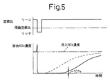
- FIG. 5 showing a variation of the exhaust NO x concentration discharged from the NO x storage catalyst
- FIG. 6 is a diagram showing the relationship between the NO x storage amount and the catalyst bed temperature Prefecture
- Figure 7 is a time chart showing NO x and SO x release control
- FIG. 8 is a view showing a map of the stored NO x amount NOXA, etc.
- FIG. 9 is a flowchart for executing processing for the NO x storage catalyst.
- FIG. 1 shows an overall view of a compression ignition type internal combustion engine.
- 1 is an engine body
- 2 is a combustion chamber of each cylinder
- 3 is an electronically controlled fuel injection valve for injecting fuel into each combustion chamber
- 4 is an intake manifold
- 5 is an exhaust manifold.
- the intake manifold 4 is connected to the outlet of the compressor 7 a of the exhaust turbocharger 7 via the intake duct 6, and the inlet of the compressor 7 a is connected to the air cleaner 9 via the intake air amount detector 8.
- a throttle valve 10 driven by a step motor is disposed in the intake duct 6, and a cooling device 11 for cooling intake air flowing through the intake duct 6 is disposed around the intake duct 6.
- a cooling device 11 for cooling intake air flowing through the intake duct 6 is disposed around the intake duct 6.
- the engine cooling water is guided into the cooling device 11, and the intake air is cooled by the engine cooling water.
- the exhaust manifold 5 is connected to an inlet of an exhaust turbine 7b of the exhaust turbocharger 7, the outlet of the exhaust turbine 7b is connected to the NO x treatment device 13 comprising a plurality of the NO x storage catalyst via a catalyst 12 having an oxidation function Is done.
- the NO x treatment device 13 is connected to the outlet of the catalyst 12 to branch the exhaust gas flow into a pair of exhaust gas flows, and to each outlet of the exhaust branch pipe 14.
- the exhaust manifold 5 is provided with a reducing agent supply valve 18 for supplying a reducing agent, for example, fuel, into the exhaust manifold.
- the exhaust manifold 5 and the intake manifold 4 are connected to each other via an exhaust gas recirculation (hereinafter referred to as EGR) passage 19, and an electronically controlled EGR control valve 20 is disposed in the EGR passage 19.
- EGR exhaust gas recirculation
- a cooling device 21 for cooling the EGR gas flowing in the EGR passage 19 is disposed around the EGR passage 19.
- the engine cooling water is guided into the cooling device 21, and the EGR gas is cooled by the engine cooling water.
- each fuel injection valve 3 is connected to a common rail 23 via a fuel supply pipe 22. Fuel is supplied into the common rail 23 from an electronically controlled fuel pump 24 with variable discharge amount, and the fuel supplied into the common rail 23 is supplied to the fuel injection valve 3 through each fuel supply pipe 22.
- the electronic control unit 30 is composed of a digital computer, and is connected to each other by a bidirectional bus 31.
- the output signal of the intake air amount detector 8 is input to the input port 35 via the corresponding AD converter 37.
- a load sensor 41 that generates an output voltage proportional to the depression amount L of the accelerator pedal 40 is connected to the accelerator pedal 40, and the output voltage of the load sensor 41 is input to the input port 35 via the corresponding AD converter 37. Is done.
- the input port 35 is connected to a crank angle sensor 42 that generates an output pulse every time the crankshaft rotates, for example, 15 °.
- FIG. 2 is a side cross-sectional view of the upstream NO x storage catalysts 15a and 15b. As shown in FIG. 2, a large number of exhaust gas flow holes, that is, cells 43 extending in the exhaust gas flow direction are formed on the bases of the upstream NO x storage catalysts 15a and 15b.
- the downstream side NO x storage catalyst 17 also has a cross-sectional shape similar to that shown in FIG.
- FIGS. 3A, 3B are schematically the cross-section of the surface part of this catalyst carrier 45 Show.
- the noble metal catalyst 46 is dispersedly supported on the surface of the catalyst carrier 45, and a layer of NO x absorbent 47 is formed on the surface of the catalyst carrier 45.
- platinum Pt is used as the noble metal catalyst 46, and the constituents of the NO x absorbent 47 are, for example, alkali metals such as potassium K, sodium Na, cesium Cs, barium Ba, calcium Ca.
- At least one selected from alkaline earths such as these, lanthanum La, and rare earths such as yttrium Y is used.
- the air-fuel ratio of the exhaust gas the ratio of the air and fuel (hydrocarbon) supplied into the engine intake passage, the combustion chamber 2 and the exhaust passage upstream of the NO x storage catalysts 15a, 15b, 17 is called the air-fuel ratio of the exhaust gas
- the NO x absorbent 47 do absorbing and releasing action of the NO x when the air-fuel ratio of the exhaust gas is absorbed NO x when the lean, the oxygen concentration in the exhaust gas to release NO x absorbed to decrease. That is, the case where barium Ba is used as a component constituting the NO x absorbent 47 will be described as an example.
- Oxygen concentration in the exhaust gas NO 2 is produced on the surface as long as the platinum Pt46 high, the NO x absorbent 47 of the NO x absorbing capability as long as NO 2 not to saturate been absorbed in the NO x absorbent 47 nitrate ions NO 3 - are produced. At this time, part of the NO contained in the exhaust gas is adsorbed by the NO x storage catalyst in the form of NO or NO 2 . In contrast, when the reducing agent is supplied from the reducing agent supply valve 18 or the air-fuel ratio in the combustion chamber 2 is made rich or stoichiometric, the exhaust gas becomes rich or stoichiometric.
- the reaction proceeds in the reverse direction (NO 3 ⁇ ⁇ NO 2 ), and thus the nitrate ion NO 3 ⁇ in the NO x absorbent 47 is in the form of NO 2 and the NO x absorbent. 47 is released. NO x being adsorbed At the same time also be released. Next, the released NO x is reduced by unburned HC and CO contained in the exhaust gas.
- NO x in the exhaust gas is absorbed or adsorbed in the NO x absorbent 47. . That is, NO x in the exhaust gas is stored in the NO x storage catalyst.
- the exhaust gas is supplied by supplying the reducing agent from the reducing agent supply valve 18 before the absorption capacity of the NO x absorbent 47 is saturated or by making the air-fuel ratio in the combustion chamber 2 rich. of the air-fuel ratio temporarily rich and thereby so that to release the NO x from the NO x absorbent 47.
- the exhaust gas contains SO x, namely SO 2, the SO 2
- SO x namely SO 2
- the SO 2 flows into the the NO x storage catalytic 15a, 15b, 17 is the is oxidized SO 3 in the platinum Pt 46.
- this SO 3 is absorbed in the NO x absorbent 47 and bonded to the barium carbonate BaCO 3 , while diffusing into the NO x absorbent 47 in the form of sulfate ions SO 4 2 ⁇ , and stable sulfate BaSO 4 is formed.
- NO x storage catalyst 15a, 15b, 17 NO x storage catalyst 15a in a state in which the temperature was raised up to release SO x temperatures above 600 ° C., the air-fuel ratio of the exhaust gas flowing into the 15b, 17 rich Then, SO x is gradually released from the NO x absorbent 47. Therefore, in the embodiment according to the present invention, when the amount of SO x stored in the NO x storage catalyst 15a, 15b, 17 exceeds the allowable value, the temperature of the NO x storage catalyst 15a, 15b, 17 is set to an SO x release temperature of 600 ° C. or more.
- the air-fuel ratio of the exhaust gas flowing into the NO x storage catalysts 15a, 15b, and 17 is made rich so that SO x is released from the NO x storage catalysts 15a, 15b, and 17.
- the space velocity in the NO x storage catalyst is slowed, the oxidizing action from NO to NO 2 is promoted, and therefore the NO x purification performance by this NO x storage catalyst can be improved.
- much the NO x purification performance can not be the amount of NO x to zero slip through the NO x storage catalyst is also improved, thus NO x further NO x storage catalyst downstream of the storage catalyst, i.e. the downstream-side NO x It is essential to arrange the storage catalyst.
- the increase of the NO x purification performance at the downstream the NO x storage catalyst is necessary to promote the oxidation action of NO to NO 2.
- the amount of the NO x that is if a large amount of the NO x is present in the exhaust gas flowing to the upstream-side NO x storage catalyst in contact with the precious metal catalyst 46 on the catalyst carrier 45 is large, therefore this case If the space velocity in the upstream NO x storage catalyst is decreased, the NO x purification ability can be increased. However, when the amount of NO x in the exhaust gas flowing in is small as in the downstream side NO x storage catalyst, the chance of NO x in the exhaust gas coming into contact with the noble metal catalyst 46 on the catalyst carrier 45 is reduced. Thus it is to increase the chance of contact between the NO x and the precious metal catalyst 46 in the exhaust gas to enhance this case the NO x purification capacity becomes the most important.
- the increase opportunities for contact between the NO x and the precious metal catalyst 46 in the exhaust gas is necessary to provide turbulence in the exhaust gas stream, an effective method therefor is to accelerate the flow speed of the exhaust gas.
- an effective method therefor is to accelerate the flow speed of the exhaust gas.
- increase the flow rate of the exhaust gas flowing into the downstream-side NO x storage catalyst i.e. that the NO x purification rate by the NO x treatment device 13 when faster the spatial velocity in the downstream the NO x storage catalyst is increased by a large margin It turns out.
- the exhaust passage space formed between the words and the downstream end of the upstream-side NO x storing catalyst and the downstream-side NO x storing catalyst is strongly disturbed in the exhaust passage space. Therefore, if such an exhaust passage space is formed, strong turbulence can be generated in the exhaust gas flowing into the downstream side NO x storage catalyst, and thus the NO x purification performance in the downstream side NO x storage catalyst. Can be increased.
- the NO x storage catalyst disposed in the engine exhaust passage is an upstream NO x storage catalyst, and a downstream disposed from the downstream end of the upstream NO x storage catalyst with an exhaust passage space therebetween. made from the side the NO x storage catalyst, the upstream-side NO x storing catalyst and the downstream the NO x storage catalyst is formed such that the space velocity in the downstream the NO x storage catalyst is greater than the space velocity in the upstream storage catalyst.
- the exhaust passage space is provided between the upstream NO x storage catalyst and the downstream NO x storage catalyst, and the space velocity in the downstream NO x storage catalyst is the space velocity in the upstream storage catalyst. It is characterized by being larger than.
- FIGS. 4A-4D, 5 and 6 show one experimental example demonstrating this feature. That is, FIGS. 4A to 4D show cases where the arrangement of the NO x storage catalyst is variously changed in the state where the total volume of all the NO x storage catalysts is kept the same in the NO x treatment device 13. Incidentally, NO x treatment device 13 shown in FIG. 1 is shown in Figure 4C in these of the NO x treatment device 13.
- FIG. 5 shows a variation of the exhaust NO x concentration in the exhaust gas flowing out in the case where the air-fuel ratio of the exhaust gas flowing into the NO x treatment device 13 temporarily from lean to rich from the NO x treatment device 13 ing.
- the inflow concentration of NO x in the exhaust gas flowing into the NO x treatment device 13 is shown by a dashed line in FIG. 5.
- the exhaust NO x concentration air-fuel ratio is made rich in the exhaust gas as shown in Figure 5 becomes zero as shown by the solid line, and then gradually increase after being kept in interim pleasure zero.
- exhaust NO all of the NO x x concentration at the time of zero contained in the exhaust gas are occluded in the NO x storage catalyst, and the exhaust NO all NO x contained in the exhaust gas is no longer E occlude x concentration begins to rise.
- the exhaust NO x concentration as shown in FIG.
- the NO x amount occluded in the NOx represents the NO x occlusion amount that can be occluded by the NO x occlusion catalyst.
- the vertical axis in FIG. 6 represents the NO x storage amount that can be stored by this NO x storage catalyst.
- the horizontal axis indicates the bed temperature of the NO x storage catalyst.
- FIG. 6B shows the NO x storage amount as shown in FIG. 4B.
- a pair of upstream the NO x storage catalytic 51a, 51b and, respectively corresponding upstream the NO x storage catalyst 51a, the NO x storage when provided downstream the NO x storage catalyst 52a disposed on the downstream side of 51b, and 52b represents the amount
- C of FIG. 6 shows the the NO x storage amount in the embodiment according to the present invention shown in FIG. 4C.
- Figure 4A is composed of a pair of the NO x storage catalytic 50a, 50b of the NO x storage catalyst is arranged in parallel to slow the space velocity in the NO x storage catalyst, a change in the exhaust NO x concentration in this case is 5 In FIG. As can be seen from FIG.
- FIG. 4A the amount of NO x discharged from the NO x treatment device 13 increases, and therefore the amount of stored NO x decreases as shown in FIG. 6A. That is, as shown in FIG. 4A, a high NO x purification performance cannot be obtained simply by arranging a large pair of NO x storage catalysts 50a and 50b in parallel.
- Figure 4B is upstream the NO x storage catalyst 51a, respectively the discharged NO x from 51b s corresponding downstream the NO x storage catalyst 52a, shows a case in which so as to occluded in 52b.
- the space velocity is slower at the upstream the NO x storage catalytic 15a, 15b because upstream the NO x storage catalyst 15a, the volume of 15b is larger than the case shown in Figure 4B in the case shown in FIG. 4C , it is possible to increase upstream the NO x storage catalyst 15a, the the NO x storage amount in 15b and thus.
- a pair of upstream the NO x storage catalyst 15a, a space velocity in the downstream-side NO x storage catalyst 17 since the exhaust gas flowing out of the 15b flows into a downstream-side NO x storage catalyst 17 upstream the NO x storage catalyst 15a , 15b is about twice as fast as the space velocity.
- the pair of upstream-side NO x storage catalyst 15a, and the exhaust collecting pipe 16 is formed an exhaust passage space 54 between the 15b and the downstream-side NO x storage catalyst 17, each in the exhaust passage space 54
- the exhaust gas flowing out from the upstream side NO x storage catalysts 15a and 15b collides violently.
- a strong turbulence is given to the exhaust gas flow flowing into the downstream side NO x storage catalyst 17, thereby increasing the amount of NO x stored in the downstream side NO x storage catalyst 17.
- the NO x storage amount as shown by C in FIG.
- the side NO x storage catalyst can be composed of a plurality of NO x storage catalysts arranged in parallel or one NO x storage catalyst, that is, at least one NO x storage catalyst.
- the total cross-sectional area of the upstream NO x storage catalyst 15a, 15b, 15 is the downstream NO x storage catalyst 17. This is larger than the total cross-sectional area.
- occlusion effects of the NO x in the embodiment according to the present invention is mainly upstream the NO x storage catalytic 15,15a, made by 15b, thus upstream the NO x storage catalytic 15,15a to increase the NO x storage amount 15b, it is preferable to increase the NO x storage capacity.
- NO x to are inserted in the NO x storage catalyst is necessary that the NO x reaches the the NO x absorbent 47, for enhancing the NO x storage capacity thus reach the NO x absorbent 47 it is necessary to increase the amount of NO x.
- the number of cells 43 per unit sectional area of the upstream NO x storage catalyst 15, 15 a, 15 b is the number of cells 43 per unit sectional area of the downstream NO x storage catalyst 17.
- the basicity of the downstream side NO x storage catalyst 17 is weaker than that of the upstream side NO x storage catalyst 15, 15a, 15b. Downstream the NO x storage catalyst 17 of the basic upstream the NO x storage catalyst 15, 15a, one way to weaker than basic 15b less the amount of the NO x absorbent 47 of the downstream-side NO x storage catalyst 17 It is a method to do.
- the amount of the NO x absorbent 47 of the downstream side NO x storage catalyst 17 is made smaller than the amount of the NO x absorbent 47 of each upstream side NO x storage catalyst 15, 15a, 15b.
- the amount of potassium K supported by the downstream NO x storage catalyst 17 is approximately 1/3 of the amount of potassium K supported by each upstream NO x storage catalyst 15a, 15b. Has been.
- NO x downstream the NO x storage catalyst 17 As the absorbent 47, a component that is less basic than the NO x absorbent 47 of the upstream NO x storage catalyst 15, 15a, 15b is used.
- an alkali metal such as potassium K or sodium Na is used as the NO x absorbent 47 of the upstream side NO x storage catalyst 15, 15 a, 15 b, and barium Ba is used as the NO x absorbent 47 of the downstream side NO x storage catalyst 17.
- Alkaline earth metals such as are used.
- the air-fuel ratio in the rich upstream the NO x storage catalytic 15,15a exhaust gas when to release the NO x from 15b, that the released NO x is occluded again on the downstream side the NO x storage catalyst 17
- the space velocity in the downstream the NO x storage catalyst 17 is as fast as in the upstream the NO x storage catalyst 15, 15a, SO x released from 15b is relatively fast downstream the NO x storage catalyst 17 Go through.
- SO x can be desorbed in a short time.
- the air-fuel ratio A / F of the exhaust gas flowing into the NO x treatment device 13 is temporarily made rich every time the total NO x amount ⁇ NOX reaches the allowable value NX.
- NO x is released from all the NO x storage catalysts 15, 15 a, 15 b, 17.
- the NO x storage catalytic 15,15a as described above, 15b, 17 from SO x released the NO x storage catalytic 15,15a in order to raise 15b, 17 a temperature of up to release SO x temperature and the NO x storage It is necessary to make the air-fuel ratio of the exhaust gas flowing into the catalysts 15, 15a, 15b, 17 rich. Therefore, in the embodiment according to the present invention, as shown in FIG.
- step 60 discharge amount of NO x NOXA per unit time from the map shown in FIG. 8A is calculated.
- this NOXA is added to the amount of NO x ⁇ NOX that stored in the NO x storage catalyst 15,15a, 15b, 17.
- step 62 occluded amount of NO x ⁇ NOX whether exceeds the allowable value NX is determined.
- Rich processing rows to switch temporarily from lean air-fuel ratio of the exhaust gas flowing into the NO x treatment device 13 by the reducing agent supplied from the reducing agent feed valve 18 proceeds to step 63 to rich when a .SIGMA.NOX> NX ⁇ NOX is cleared.
- step 64 the discharge amount of SO x SOXZ per unit time from the map shown in FIG. 8B is calculated.
- this SOXZ is added to the SO x amount ⁇ SOX stored in the NO x storage catalysts 15, 15a, 15b, and 17.
- step 67 the air-fuel ratio of the exhaust gas flowing into the NO x treatment device 13 is made lean.
- the temperature increase control is performed to raise the temperature T of each NO x storage catalyst 15, 15 a, 15 b, 17 to the SO x release temperature TX by supplying the reducing agent from the reducing agent supply valve 18 while maintaining.
- the reducing agent supplied from the step 68 in the reducing agent supply valve 18 is then, or to maintain the air-fuel ratio of the exhaust gas flowing into the NO x treatment device 13 by maintaining the air-fuel ratio in the combustion chamber 2 rich rich Rich processing is performed and ⁇ SOX is cleared.
Landscapes
- Engineering & Computer Science (AREA)
- Chemical & Material Sciences (AREA)
- Combustion & Propulsion (AREA)
- Mechanical Engineering (AREA)
- General Engineering & Computer Science (AREA)
- Chemical Kinetics & Catalysis (AREA)
- Health & Medical Sciences (AREA)
- Biomedical Technology (AREA)
- Environmental & Geological Engineering (AREA)
- Analytical Chemistry (AREA)
- General Chemical & Material Sciences (AREA)
- Oil, Petroleum & Natural Gas (AREA)
- Exhaust Gas After Treatment (AREA)
- Exhaust Gas Treatment By Means Of Catalyst (AREA)
Abstract
Priority Applications (5)
| Application Number | Priority Date | Filing Date | Title |
|---|---|---|---|
| EP09839678A EP2395210A4 (fr) | 2009-02-06 | 2009-02-06 | Dispositif de nettoyage d'échappement pour moteur à combustion interne |
| CN200980120327XA CN102216577A (zh) | 2009-02-06 | 2009-02-06 | 内燃机的排气净化装置 |
| JP2010549336A JPWO2010089901A1 (ja) | 2009-02-06 | 2009-02-06 | 内燃機関の排気浄化装置 |
| US12/999,493 US20110088377A1 (en) | 2009-02-06 | 2009-02-06 | Exhaust purification device of internal combustion engine |
| PCT/JP2009/052448 WO2010089901A1 (fr) | 2009-02-06 | 2009-02-06 | Dispositif de nettoyage d'échappement pour moteur à combustion interne |
Applications Claiming Priority (1)
| Application Number | Priority Date | Filing Date | Title |
|---|---|---|---|
| PCT/JP2009/052448 WO2010089901A1 (fr) | 2009-02-06 | 2009-02-06 | Dispositif de nettoyage d'échappement pour moteur à combustion interne |
Publications (1)
| Publication Number | Publication Date |
|---|---|
| WO2010089901A1 true WO2010089901A1 (fr) | 2010-08-12 |
Family
ID=42541821
Family Applications (1)
| Application Number | Title | Priority Date | Filing Date |
|---|---|---|---|
| PCT/JP2009/052448 Ceased WO2010089901A1 (fr) | 2009-02-06 | 2009-02-06 | Dispositif de nettoyage d'échappement pour moteur à combustion interne |
Country Status (5)
| Country | Link |
|---|---|
| US (1) | US20110088377A1 (fr) |
| EP (1) | EP2395210A4 (fr) |
| JP (1) | JPWO2010089901A1 (fr) |
| CN (1) | CN102216577A (fr) |
| WO (1) | WO2010089901A1 (fr) |
Families Citing this family (1)
| Publication number | Priority date | Publication date | Assignee | Title |
|---|---|---|---|---|
| DE102007008954B4 (de) * | 2007-02-21 | 2009-12-17 | Umicore Ag & Co. Kg | Katalysatorsystem und seine Verwendung |
Citations (5)
| Publication number | Priority date | Publication date | Assignee | Title |
|---|---|---|---|---|
| JPH04214919A (ja) * | 1990-06-25 | 1992-08-05 | Toyota Motor Corp | 内燃機関の排気浄化装置 |
| JPH05272332A (ja) * | 1992-03-25 | 1993-10-19 | Toyota Motor Corp | NOx浄化装置 |
| JP2006077710A (ja) * | 2004-09-10 | 2006-03-23 | Toyota Motor Corp | 内燃機関の排気浄化システム |
| JP2006233894A (ja) * | 2005-02-25 | 2006-09-07 | Toyota Motor Corp | 内燃機関の排気浄化装置 |
| JP2008075585A (ja) * | 2006-09-22 | 2008-04-03 | Toyota Motor Corp | 内燃機関の排気浄化装置 |
Family Cites Families (17)
| Publication number | Priority date | Publication date | Assignee | Title |
|---|---|---|---|---|
| WO1993025805A1 (fr) * | 1992-06-12 | 1993-12-23 | Toyota Jidosha Kabushiki Kaisha | Systeme de limitation d'emission de gaz d'echappement pour moteur a combustion interne |
| JP2605553B2 (ja) * | 1992-08-04 | 1997-04-30 | トヨタ自動車株式会社 | 内燃機関の排気浄化装置 |
| JP3237611B2 (ja) * | 1997-11-11 | 2001-12-10 | トヨタ自動車株式会社 | 内燃機関の排気浄化装置 |
| US6237330B1 (en) * | 1998-04-15 | 2001-05-29 | Nissan Motor Co., Ltd. | Exhaust purification device for internal combustion engine |
| US6289672B1 (en) * | 1998-07-21 | 2001-09-18 | Toyota Jidosha Kabushiki Kaisha | Exhaust gas purification device for an internal combustion engine |
| JP3370957B2 (ja) * | 1998-09-18 | 2003-01-27 | トヨタ自動車株式会社 | 内燃機関の排気浄化装置 |
| US6375910B1 (en) * | 1999-04-02 | 2002-04-23 | Engelhard Corporation | Multi-zoned catalytic trap and methods of making and using the same |
| DE19918756A1 (de) * | 1999-04-24 | 2000-10-26 | Volkswagen Ag | Anordnung zur Reinigung eines Abgases einer Verbrennungsmaschine und Verfahren zum Betrieb einer solchen Anordnung |
| DE10015330A1 (de) * | 2000-03-28 | 2002-02-21 | Volkswagen Ag | Verfahren und Vorrichtung zur Abgasreinigung |
| JP3733834B2 (ja) * | 2000-05-02 | 2006-01-11 | 日産自動車株式会社 | 内燃機関の排気浄化装置 |
| US6502387B1 (en) * | 2001-06-19 | 2003-01-07 | Ford Global Technologies, Inc. | Method and system for controlling storage and release of exhaust gas constituents in an emission control device |
| US6650991B2 (en) * | 2001-06-19 | 2003-11-18 | Ford Global Technologies, Llc | Closed-loop method and system for purging a vehicle emission control |
| GB0125729D0 (en) * | 2001-10-26 | 2001-12-19 | Johnson Matthey Plc | Catalyst substrate |
| JP4120563B2 (ja) * | 2003-11-06 | 2008-07-16 | トヨタ自動車株式会社 | 内燃機関の排気浄化装置 |
| JP2005224682A (ja) * | 2004-02-12 | 2005-08-25 | Hitachi Ltd | 内燃機関用排ガス浄化装置及び排ガス浄化方法 |
| JP4466474B2 (ja) * | 2005-05-20 | 2010-05-26 | トヨタ自動車株式会社 | 内燃機関の排気浄化装置 |
| DE102008048854B4 (de) * | 2008-09-25 | 2012-08-02 | Umicore Ag & Co. Kg | Regelungsstrategie für ein Katalysatorkonzept zur Abgasnachbehandlung mit mehreren Stickoxid-Speicherkatalysatoren |
-
2009
- 2009-02-06 WO PCT/JP2009/052448 patent/WO2010089901A1/fr not_active Ceased
- 2009-02-06 EP EP09839678A patent/EP2395210A4/fr not_active Withdrawn
- 2009-02-06 JP JP2010549336A patent/JPWO2010089901A1/ja active Pending
- 2009-02-06 US US12/999,493 patent/US20110088377A1/en not_active Abandoned
- 2009-02-06 CN CN200980120327XA patent/CN102216577A/zh active Pending
Patent Citations (5)
| Publication number | Priority date | Publication date | Assignee | Title |
|---|---|---|---|---|
| JPH04214919A (ja) * | 1990-06-25 | 1992-08-05 | Toyota Motor Corp | 内燃機関の排気浄化装置 |
| JPH05272332A (ja) * | 1992-03-25 | 1993-10-19 | Toyota Motor Corp | NOx浄化装置 |
| JP2006077710A (ja) * | 2004-09-10 | 2006-03-23 | Toyota Motor Corp | 内燃機関の排気浄化システム |
| JP2006233894A (ja) * | 2005-02-25 | 2006-09-07 | Toyota Motor Corp | 内燃機関の排気浄化装置 |
| JP2008075585A (ja) * | 2006-09-22 | 2008-04-03 | Toyota Motor Corp | 内燃機関の排気浄化装置 |
Non-Patent Citations (1)
| Title |
|---|
| See also references of EP2395210A4 * |
Also Published As
| Publication number | Publication date |
|---|---|
| EP2395210A1 (fr) | 2011-12-14 |
| CN102216577A (zh) | 2011-10-12 |
| US20110088377A1 (en) | 2011-04-21 |
| EP2395210A4 (fr) | 2012-08-01 |
| JPWO2010089901A1 (ja) | 2012-08-09 |
Similar Documents
| Publication | Publication Date | Title |
|---|---|---|
| JP4270201B2 (ja) | 内燃機関 | |
| JP4420048B2 (ja) | 内燃機関の排気浄化装置 | |
| JP2009114879A (ja) | 内燃機関の排気浄化装置 | |
| JP5018325B2 (ja) | 内燃機関の排気浄化装置 | |
| JP4697305B2 (ja) | 内燃機関の排気浄化装置 | |
| JP5664801B2 (ja) | 火花点火式内燃機関の排気浄化装置 | |
| JP5748005B2 (ja) | 内燃機関の排気浄化装置 | |
| JP5673861B2 (ja) | 内燃機関の排気浄化装置 | |
| JP4935929B2 (ja) | 内燃機関の排気浄化装置 | |
| JP5835488B2 (ja) | 内燃機関の排気浄化装置 | |
| JP2008208739A (ja) | 内燃機関の排気浄化装置 | |
| JP2011231755A (ja) | 内燃機関の排気浄化装置 | |
| WO2010089901A1 (fr) | Dispositif de nettoyage d'échappement pour moteur à combustion interne | |
| JP2009209766A (ja) | 内燃機関の排気浄化装置 | |
| JP2008303791A (ja) | 内燃機関の排気浄化装置 | |
| JP2007231918A (ja) | 圧縮着火式内燃機関の排気浄化装置 | |
| JP4254484B2 (ja) | 内燃機関の排気浄化装置 | |
| JP4269919B2 (ja) | 内燃機関の排気浄化装置 | |
| JP4737144B2 (ja) | 内燃機関の排気浄化装置 | |
| WO2014024311A1 (fr) | Dispositif de purification de gaz d'échappement pour moteur à combustion interne et à allumage par étincelle | |
| CN102548645B (zh) | 内燃机的排气净化装置 | |
| WO2008123629A1 (fr) | Dispositif de purification de gaz d'échappement pour moteur à combustion interne | |
| JP2007231922A (ja) | 圧縮着火式内燃機関の排気浄化装置 | |
| JP4254505B2 (ja) | 内燃機関の排気浄化装置 | |
| JP2009250130A (ja) | 内燃機関の排気浄化装置 |
Legal Events
| Date | Code | Title | Description |
|---|---|---|---|
| WWE | Wipo information: entry into national phase |
Ref document number: 200980120327.X Country of ref document: CN |
|
| 121 | Ep: the epo has been informed by wipo that ep was designated in this application |
Ref document number: 09839678 Country of ref document: EP Kind code of ref document: A1 |
|
| WWE | Wipo information: entry into national phase |
Ref document number: 2010549336 Country of ref document: JP |
|
| WWE | Wipo information: entry into national phase |
Ref document number: 2009839678 Country of ref document: EP |
|
| WWE | Wipo information: entry into national phase |
Ref document number: 12999493 Country of ref document: US |
|
| NENP | Non-entry into the national phase |
Ref country code: DE |