WO2010090125A1 - 薄膜固体リチウムイオン二次電池及びその製造方法 - Google Patents
薄膜固体リチウムイオン二次電池及びその製造方法 Download PDFInfo
- Publication number
- WO2010090125A1 WO2010090125A1 PCT/JP2010/051127 JP2010051127W WO2010090125A1 WO 2010090125 A1 WO2010090125 A1 WO 2010090125A1 JP 2010051127 W JP2010051127 W JP 2010051127W WO 2010090125 A1 WO2010090125 A1 WO 2010090125A1
- Authority
- WO
- WIPO (PCT)
- Prior art keywords
- film
- negative electrode
- forming layer
- current collector
- active material
- Prior art date
- Legal status (The legal status is an assumption and is not a legal conclusion. Google has not performed a legal analysis and makes no representation as to the accuracy of the status listed.)
- Ceased
Links
Images








Classifications
-
- H—ELECTRICITY
- H01—ELECTRIC ELEMENTS
- H01M—PROCESSES OR MEANS, e.g. BATTERIES, FOR THE DIRECT CONVERSION OF CHEMICAL ENERGY INTO ELECTRICAL ENERGY
- H01M4/00—Electrodes
- H01M4/02—Electrodes composed of, or comprising, active material
- H01M4/64—Carriers or collectors
- H01M4/66—Selection of materials
-
- H—ELECTRICITY
- H01—ELECTRIC ELEMENTS
- H01M—PROCESSES OR MEANS, e.g. BATTERIES, FOR THE DIRECT CONVERSION OF CHEMICAL ENERGY INTO ELECTRICAL ENERGY
- H01M10/00—Secondary cells; Manufacture thereof
- H01M10/05—Accumulators with non-aqueous electrolyte
- H01M10/052—Li-accumulators
- H01M10/0525—Rocking-chair batteries, i.e. batteries with lithium insertion or intercalation in both electrodes; Lithium-ion batteries
-
- H—ELECTRICITY
- H01—ELECTRIC ELEMENTS
- H01M—PROCESSES OR MEANS, e.g. BATTERIES, FOR THE DIRECT CONVERSION OF CHEMICAL ENERGY INTO ELECTRICAL ENERGY
- H01M10/00—Secondary cells; Manufacture thereof
- H01M10/05—Accumulators with non-aqueous electrolyte
- H01M10/056—Accumulators with non-aqueous electrolyte characterised by the materials used as electrolytes, e.g. mixed inorganic/organic electrolytes
- H01M10/0561—Accumulators with non-aqueous electrolyte characterised by the materials used as electrolytes, e.g. mixed inorganic/organic electrolytes the electrolyte being constituted of inorganic materials only
- H01M10/0562—Solid materials
-
- H—ELECTRICITY
- H01—ELECTRIC ELEMENTS
- H01M—PROCESSES OR MEANS, e.g. BATTERIES, FOR THE DIRECT CONVERSION OF CHEMICAL ENERGY INTO ELECTRICAL ENERGY
- H01M10/00—Secondary cells; Manufacture thereof
- H01M10/05—Accumulators with non-aqueous electrolyte
- H01M10/058—Construction or manufacture
-
- H—ELECTRICITY
- H01—ELECTRIC ELEMENTS
- H01M—PROCESSES OR MEANS, e.g. BATTERIES, FOR THE DIRECT CONVERSION OF CHEMICAL ENERGY INTO ELECTRICAL ENERGY
- H01M10/00—Secondary cells; Manufacture thereof
- H01M10/05—Accumulators with non-aqueous electrolyte
- H01M10/058—Construction or manufacture
- H01M10/0585—Construction or manufacture of accumulators having only flat construction elements, i.e. flat positive electrodes, flat negative electrodes and flat separators
-
- H—ELECTRICITY
- H01—ELECTRIC ELEMENTS
- H01M—PROCESSES OR MEANS, e.g. BATTERIES, FOR THE DIRECT CONVERSION OF CHEMICAL ENERGY INTO ELECTRICAL ENERGY
- H01M4/00—Electrodes
- H01M4/02—Electrodes composed of, or comprising, active material
- H01M4/13—Electrodes for accumulators with non-aqueous electrolyte, e.g. for lithium-accumulators; Processes of manufacture thereof
- H01M4/131—Electrodes based on mixed oxides or hydroxides, or on mixtures of oxides or hydroxides, e.g. LiCoOx
-
- H—ELECTRICITY
- H01—ELECTRIC ELEMENTS
- H01M—PROCESSES OR MEANS, e.g. BATTERIES, FOR THE DIRECT CONVERSION OF CHEMICAL ENERGY INTO ELECTRICAL ENERGY
- H01M4/00—Electrodes
- H01M4/02—Electrodes composed of, or comprising, active material
- H01M4/13—Electrodes for accumulators with non-aqueous electrolyte, e.g. for lithium-accumulators; Processes of manufacture thereof
- H01M4/136—Electrodes based on inorganic compounds other than oxides or hydroxides, e.g. sulfides, selenides, tellurides, halogenides or LiCoFy
-
- H—ELECTRICITY
- H01—ELECTRIC ELEMENTS
- H01M—PROCESSES OR MEANS, e.g. BATTERIES, FOR THE DIRECT CONVERSION OF CHEMICAL ENERGY INTO ELECTRICAL ENERGY
- H01M4/00—Electrodes
- H01M4/02—Electrodes composed of, or comprising, active material
- H01M4/36—Selection of substances as active materials, active masses, active liquids
- H01M4/48—Selection of substances as active materials, active masses, active liquids of inorganic oxides or hydroxides
- H01M4/50—Selection of substances as active materials, active masses, active liquids of inorganic oxides or hydroxides of manganese
- H01M4/505—Selection of substances as active materials, active masses, active liquids of inorganic oxides or hydroxides of manganese of mixed oxides or hydroxides containing manganese for inserting or intercalating light metals, e.g. LiMn2O4 or LiMn2OxFy
-
- H—ELECTRICITY
- H01—ELECTRIC ELEMENTS
- H01M—PROCESSES OR MEANS, e.g. BATTERIES, FOR THE DIRECT CONVERSION OF CHEMICAL ENERGY INTO ELECTRICAL ENERGY
- H01M6/00—Primary cells; Manufacture thereof
- H01M6/40—Printed batteries, e.g. thin film batteries
-
- H—ELECTRICITY
- H01—ELECTRIC ELEMENTS
- H01M—PROCESSES OR MEANS, e.g. BATTERIES, FOR THE DIRECT CONVERSION OF CHEMICAL ENERGY INTO ELECTRICAL ENERGY
- H01M10/00—Secondary cells; Manufacture thereof
- H01M10/05—Accumulators with non-aqueous electrolyte
-
- H—ELECTRICITY
- H01—ELECTRIC ELEMENTS
- H01M—PROCESSES OR MEANS, e.g. BATTERIES, FOR THE DIRECT CONVERSION OF CHEMICAL ENERGY INTO ELECTRICAL ENERGY
- H01M10/00—Secondary cells; Manufacture thereof
- H01M10/05—Accumulators with non-aqueous electrolyte
- H01M10/054—Accumulators with insertion or intercalation of metals other than lithium, e.g. with magnesium or aluminium
-
- H—ELECTRICITY
- H01—ELECTRIC ELEMENTS
- H01M—PROCESSES OR MEANS, e.g. BATTERIES, FOR THE DIRECT CONVERSION OF CHEMICAL ENERGY INTO ELECTRICAL ENERGY
- H01M10/00—Secondary cells; Manufacture thereof
- H01M10/06—Lead-acid accumulators
- H01M10/12—Construction or manufacture
- H01M10/126—Small-sized flat cells or batteries for portable equipment
-
- H—ELECTRICITY
- H01—ELECTRIC ELEMENTS
- H01M—PROCESSES OR MEANS, e.g. BATTERIES, FOR THE DIRECT CONVERSION OF CHEMICAL ENERGY INTO ELECTRICAL ENERGY
- H01M4/00—Electrodes
- H01M4/02—Electrodes composed of, or comprising, active material
- H01M4/13—Electrodes for accumulators with non-aqueous electrolyte, e.g. for lithium-accumulators; Processes of manufacture thereof
- H01M4/139—Processes of manufacture
- H01M4/1391—Processes of manufacture of electrodes based on mixed oxides or hydroxides, or on mixtures of oxides or hydroxides, e.g. LiCoOx
-
- H—ELECTRICITY
- H01—ELECTRIC ELEMENTS
- H01M—PROCESSES OR MEANS, e.g. BATTERIES, FOR THE DIRECT CONVERSION OF CHEMICAL ENERGY INTO ELECTRICAL ENERGY
- H01M4/00—Electrodes
- H01M4/02—Electrodes composed of, or comprising, active material
- H01M4/13—Electrodes for accumulators with non-aqueous electrolyte, e.g. for lithium-accumulators; Processes of manufacture thereof
- H01M4/139—Processes of manufacture
- H01M4/1397—Processes of manufacture of electrodes based on inorganic compounds other than oxides or hydroxides, e.g. sulfides, selenides, tellurides, halogenides or LiCoFy
-
- Y—GENERAL TAGGING OF NEW TECHNOLOGICAL DEVELOPMENTS; GENERAL TAGGING OF CROSS-SECTIONAL TECHNOLOGIES SPANNING OVER SEVERAL SECTIONS OF THE IPC; TECHNICAL SUBJECTS COVERED BY FORMER USPC CROSS-REFERENCE ART COLLECTIONS [XRACs] AND DIGESTS
- Y02—TECHNOLOGIES OR APPLICATIONS FOR MITIGATION OR ADAPTATION AGAINST CLIMATE CHANGE
- Y02E—REDUCTION OF GREENHOUSE GAS [GHG] EMISSIONS, RELATED TO ENERGY GENERATION, TRANSMISSION OR DISTRIBUTION
- Y02E60/00—Enabling technologies; Technologies with a potential or indirect contribution to GHG emissions mitigation
- Y02E60/10—Energy storage using batteries
-
- Y—GENERAL TAGGING OF NEW TECHNOLOGICAL DEVELOPMENTS; GENERAL TAGGING OF CROSS-SECTIONAL TECHNOLOGIES SPANNING OVER SEVERAL SECTIONS OF THE IPC; TECHNICAL SUBJECTS COVERED BY FORMER USPC CROSS-REFERENCE ART COLLECTIONS [XRACs] AND DIGESTS
- Y02—TECHNOLOGIES OR APPLICATIONS FOR MITIGATION OR ADAPTATION AGAINST CLIMATE CHANGE
- Y02P—CLIMATE CHANGE MITIGATION TECHNOLOGIES IN THE PRODUCTION OR PROCESSING OF GOODS
- Y02P70/00—Climate change mitigation technologies in the production process for final industrial or consumer products
- Y02P70/50—Manufacturing or production processes characterised by the final manufactured product
-
- Y—GENERAL TAGGING OF NEW TECHNOLOGICAL DEVELOPMENTS; GENERAL TAGGING OF CROSS-SECTIONAL TECHNOLOGIES SPANNING OVER SEVERAL SECTIONS OF THE IPC; TECHNICAL SUBJECTS COVERED BY FORMER USPC CROSS-REFERENCE ART COLLECTIONS [XRACs] AND DIGESTS
- Y10—TECHNICAL SUBJECTS COVERED BY FORMER USPC
- Y10T—TECHNICAL SUBJECTS COVERED BY FORMER US CLASSIFICATION
- Y10T29/00—Metal working
- Y10T29/49—Method of mechanical manufacture
- Y10T29/49002—Electrical device making
- Y10T29/49108—Electric battery cell making
-
- Y—GENERAL TAGGING OF NEW TECHNOLOGICAL DEVELOPMENTS; GENERAL TAGGING OF CROSS-SECTIONAL TECHNOLOGIES SPANNING OVER SEVERAL SECTIONS OF THE IPC; TECHNICAL SUBJECTS COVERED BY FORMER USPC CROSS-REFERENCE ART COLLECTIONS [XRACs] AND DIGESTS
- Y10—TECHNICAL SUBJECTS COVERED BY FORMER USPC
- Y10T—TECHNICAL SUBJECTS COVERED BY FORMER US CLASSIFICATION
- Y10T29/00—Metal working
- Y10T29/49—Method of mechanical manufacture
- Y10T29/49002—Electrical device making
- Y10T29/49108—Electric battery cell making
- Y10T29/49115—Electric battery cell making including coating or impregnating
Definitions
- the present invention relates to a lithium ion battery, and more particularly, to a thin film solid lithium ion secondary battery in which all layers formed on a substrate and constituting the battery can be formed by a dry process, and a method for manufacturing the same.
- Lithium ion secondary batteries have a higher energy density than other secondary batteries, have excellent charge / discharge cycle characteristics, and are widely used as power sources for portable electronic devices.
- Lithium ion secondary batteries using an electrolytic solution as an electrolyte have limitations in miniaturization and thickness reduction, and polymer batteries using a gel electrolyte and thin film solid batteries using a solid electrolyte have been developed.
- a polymer battery using a gel electrolyte can be made thinner and smaller than a battery using an electrolyte solution, but there is a limit to making the gel electrolyte thinner and smaller in order to securely seal the gel electrolyte. .
- a thin-film solid battery using a solid electrolyte is composed of a layer formed on a substrate, that is, a negative electrode current collector film, a negative electrode active material film, a solid electrolyte film, a positive electrode active material film, and a positive electrode current collector film.
- a thin solid electrolyte film as a substrate, it is possible to further reduce the thickness and size.
- the thin film solid battery uses a solid non-aqueous electrolyte as an electrolyte, and all the layers constituting the battery can be made solid. Therefore, there is no possibility of deterioration due to liquid leakage, and no member for liquid leakage or corrosion is required unlike a polymer battery using a gel electrolyte, so that the manufacturing process can be simplified and safety is high. Is done.
- thin-film solid-state batteries can be incorporated on an electric circuit board on-chip, and if a thin-film solid-state battery is formed on a polymer substrate as an electric circuit board, it can be bent.
- a flexible battery that can be used is also possible. For example, it can be incorporated into card-type electronic money, an RFID tag, or the like.
- Patent Document 1 entitled “Semiconductor Substrate Mounted Secondary Battery” has the following description.
- an insulating film is formed on a silicon substrate, a wiring electrode is formed thereon, and a positive electrode and a negative electrode are arranged on the wiring electrode. That is, the positive electrode and the negative electrode are not laminated.
- the thickness of the battery itself can be made thinner.
- the substrate can be changed to an insulator.
- Patent Document 2 described later entitled “Thin-film solid secondary battery and composite device including the same” has the following description.
- the lithium ion thin film solid secondary battery of Patent Document 2 has a positive electrode side current collector layer (positive electrode current collector layer), a positive electrode active material layer, a solid electrolyte layer, a negative electrode active material layer, and a negative electrode side current collector on a substrate.
- An electric current layer (negative electrode current collector layer) and a moisture prevention film are sequentially laminated.
- the order of stacking on the substrate may be the order of the current collector layer on the negative electrode side, the negative electrode active material layer, the solid electrolyte layer, the positive electrode active material layer, the current collector layer on the positive electrode side, and the moisture prevention film. .
- the substrate glass, semiconductor silicon, ceramic, stainless steel, a resin substrate, or the like can be used.
- the resin substrate polyimide, PET (polyethylene terephthalate), or the like can be used.
- a thin film that can be bent on the substrate can be used as long as it can be handled without losing its shape. It is more preferable that these substrates have additional characteristics such as increasing transparency, preventing diffusion of alkali elements such as Na, increasing heat resistance, and providing gas barrier properties.
- a substrate on which a thin film such as SiO 2 or TiO 2 is formed by sputtering or the like may be used.
- Patent Document 3 titled “All-solid-state lithium secondary battery manufacturing method and all-solid-state lithium secondary battery” avoids a short circuit between the positive electrode film and the negative electrode film at the battery edge. There is a description of an all solid-state lithium secondary battery capable of producing
- Non-Patent Document 1 described later has a description regarding the production of a Li battery using a thin film formed by a sputtering method.
- Carbon is widely used as the negative electrode of conventional bulk Li batteries, and other materials have been studied, but it is considered difficult to put it to practical use in terms of durability.
- the use of Li metal as a material having a high capacity for constituting the negative electrode is often used in experiments relating to lithium ion secondary batteries, and a high potential can be obtained.
- the reason why it was not practical to use Li metal as a constituent material of the negative electrode is that Li grows in a needle shape when Li is deposited on the metal surface on the negative electrode side, the activity decreases and the battery characteristics deteriorate rapidly. This is because there was a problem in durability.
- Non-patent document 2 describes a lithium-free thin film battery.
- JP 2008-226728 A paragraphs 0024 to 0025, FIG. 1
- JP 2008-282687 A paragraphs 0017 to 0027
- Non-Patent Document 1 can not only form a thin film by a sputtering method, but also functions in an amorphous state, and thus does not require crystallization by annealing.
- Li-containing metal oxide crystals such as LiCoO 2 , LiMn 2 O 4 , LiFePO 4 , LiNiO 2, and the like. Since these are usually used in a crystalline phase, conventionally, when a film is formed by a thin film formation process such as sputtering, heating of the substrate during film formation and post-annealing after film formation are necessary. For this reason, a high heat-resistant material is used for the substrate, and there is a problem that the cost becomes high.
- the heating process decreases the takt time, and further causes the oxidation of the electrode and causes a short circuit between the electrodes due to a structural change when the positive electrode material is crystallized, which causes a decrease in yield.
- the positive electrode active material is amorphous, the voltage drop becomes a problem because the internal resistance is high.
- a plastic substrate From the viewpoint of battery manufacturing cost, it is preferable to use a plastic substrate, and it is also preferable to use a plastic substrate from the viewpoint of using a flexible substrate.
- LiCoO 2 , LiMn 2 O 4 , LiFePO 4 , LiNiO 2 or the like used for the positive electrode is preferably formed on a plastic substrate at room temperature without post-annealing from the viewpoint of battery manufacturing cost.
- the charge / discharge experiment of the manufactured battery is performed in a dry room or an inert gas such as Ar or nitrogen. Is running in an enclosed environment.
- the reason for conducting charge / discharge experiments on batteries manufactured in an inert gas environment is that each layer and substrate constituting the battery are easily affected by moisture contained in the atmosphere, and are rapidly deteriorated based on moisture. As it is, it is not practical.
- Non-Patent Document 2 In the technique described in Non-Patent Document 2, an attempt has been made to use a negative electrode in which Li is deposited in a thin-film battery, and the negative electrode active material does not exist in the initial stage. Li is deposited, and this becomes a substantially negative electrode active material. However, the result is that the durability against repeated charge and discharge is poor and it cannot be said that it is practical.
- the present invention has been made in order to solve the above-described problems.
- the object of the present invention is to realize charge / discharge in the atmosphere even when the film constituting the battery is formed of an amorphous film. It is an object of the present invention to provide a high-performance and inexpensive thin-film solid lithium ion secondary battery that can be stably driven and can be manufactured stably and with high yield, and a method for manufacturing the same.
- the present invention includes an electrically insulating substrate, a positive electrode side current collector film, a positive electrode active material film, a solid electrolyte film, a negative electrode potential forming layer, and a negative electrode side current collector film.
- the body film, the positive electrode active material film, the solid electrolyte film, the negative electrode potential forming layer, and the negative electrode side current collector film are formed on the electrically insulating substrate, and the negative electrode potential forming layer is a layer formed of a material different from the negative electrode active material.
- the present invention relates to a thin film solid lithium ion secondary battery, which is a layer provided to form a negative electrode potential during charging.
- the present invention also includes a step of forming a positive electrode side current collector film, a step of forming a positive electrode active material film, a step of forming a solid electrolyte film, a step of forming a negative electrode potential forming layer, a negative electrode side current collector,
- the negative electrode potential forming layer is formed of a material different from the negative electrode active material, and is formed in contact with the negative electrode current collector film and the solid electrolyte film.
- the present invention relates to a method for manufacturing a thin film solid lithium ion secondary battery, which is a layer provided to form a negative electrode potential.
- the step of forming the positive electrode side current collector film, the step of forming the positive electrode active material film, the step of forming the solid electrolyte film, the step of forming the negative electrode potential forming layer, and the negative electrode is formed of a material different from the negative electrode active material, and is formed in contact with the negative electrode side current collector film and the solid electrolyte film. It is a layer provided to form a negative electrode potential during charging, and a layer containing excessive Li is formed at the negative electrode side interface of the solid electrolyte membrane during charging, so that a positive electrode active material film, a solid electrolyte membrane, and a negative electrode potential formation are formed.
- the layer is formed of an amorphous film, charging and discharging in the atmosphere can be realized, stable driving is possible, repeated charging and discharging characteristics and durability can be improved, and as a high-performance compact and thin-film battery Thin film solid lithium ion secondary It is possible to provide a manufacturing method of the pond.
- the negative electrode potential forming layer may be formed of the same or different positive electrode active material as the positive electrode active material film.
- the negative electrode potential forming layer is formed of a positive electrode active material that is the same as or different from the positive electrode active material film, a thin film solid lithium ion secondary battery can be configured with fewer kinds of materials.
- the negative electrode potential forming layer is preferably formed of a material containing Li, and the potential difference between the negative electrode potential forming layer and the positive electrode active material film is preferably a predetermined value (2 V) or less.
- the negative electrode potential forming layer is formed of a material containing Li, and the potential difference between the negative electrode potential forming layer and the positive electrode active material film is equal to or less than a predetermined value (2 V), a sufficient driving voltage is obtained and short-circuiting is difficult to occur.
- a thin film solid lithium ion secondary battery can be provided.
- the negative electrode potential forming layer preferably has a thickness of 2 nm or more and 20 nm or less.
- the negative electrode potential forming layer preferably has a thickness of 2 nm to 13 nm.
- a negative electrode potential can be formed in the negative electrode potential forming layer during charging, the diffusion of Li to the negative electrode side current collector film can be suppressed, and the negative electrode side current collector film can be protected, A decrease in battery capacity can be further suppressed.
- LiMn 2 O 4 is used as a material constituting the negative electrode potential forming layer, since the thickness of the negative electrode potential forming layer is 2 nm or more and 13 nm or less, the battery capacity is the theoretical capacity of the positive electrode active material (positive electrode active material).
- the molecular weight (g / mol) is calculated from the Faraday constant.), which is about 30% or more of the expected capacity.
- the film thickness of the negative electrode potential forming layer is less than 2 nm, it is difficult to form the negative electrode potential forming layer with a stable thickness during mass production, which is not practical. Further, when the film thickness of the negative electrode potential forming layer exceeds 13 nm, the battery capacity is reduced to less than about 30% of the capacity expected from the theoretical capacity of the positive electrode active material, and the battery performance deteriorates. Not right.
- the negative electrode potential forming layer may have a thickness of 3 nm to 10 nm.
- a negative electrode potential can be formed in the negative electrode potential forming layer during charging, the diffusion of Li to the negative electrode side current collector film can be suppressed, and the negative electrode side current collector film can be protected, A decrease in battery capacity can be further suppressed.
- the film thickness of the negative electrode potential forming layer is 3 nm or more and 10 nm or less. Can be formed stably with little variation in thickness, ensuring mass productivity of the battery, and maintaining the capacity of the battery at a value exceeding about 40% of the capacity expected from the theoretical capacity of the positive electrode active material It becomes a more practical battery.
- the thickness of the negative electrode potential forming layer is preferably 3 nm or more and 6 nm or less. With such a configuration, a negative electrode potential can be formed in the negative electrode potential forming layer during charging, the diffusion of Li to the negative electrode side current collector film can be suppressed, and the negative electrode side current collector film can be protected, A reduction in battery capacity can be suppressed and a large battery capacity can be maintained.
- the film thickness of the negative electrode potential forming layer is 3 nm or more and 6 nm or less. It can be kept at a value exceeding about 80% of the capacity expected from the theoretical capacity of the active material, and it becomes a more practical battery.
- the positive electrode active material film and the negative electrode potential forming layer are preferably formed of LiCoO 2 .
- the maximum capacity referred to as the maximum capacity
- the thickness of the negative electrode potential forming layer is 2 nm or more and 20 nm or less. If the battery capacity can be 55% or more of the maximum capacity and the thickness of the negative electrode potential forming layer is 2 nm or more and 13 nm or less, the battery capacity can be 65% or more of the maximum capacity.
- the battery capacity can be 75% or more of the maximum capacity, and if the thickness of the negative electrode potential formation layer is 3 nm or more and 6 nm or less, the battery capacity is reduced. It can be 90% or more of the maximum capacity.
- the positive electrode active material film and the negative electrode potential forming layer are each preferably formed of LiMn 2 O 4 .
- the maximum capacity referred to as the maximum capacity
- the thickness of the negative electrode potential forming layer is 2 nm or more and 20 nm or less. If the battery capacity can be 15% or more of the maximum capacity and the thickness of the negative electrode potential forming layer is 2 nm or more and 13 nm or less, the battery capacity can be 35% or more of the maximum capacity.
- the battery capacity can be 45% or more of the maximum capacity, and if the thickness of the negative electrode potential formation layer is 3 nm or more and 6 nm or less, the battery capacity Can be almost the maximum capacity.
- the electrically insulating substrate is a substrate formed of an organic resin, and has an insulating film formed of an inorganic material on the surface of the substrate, and the positive electrode side current collector film and / or the negative electrode side current collector film are insulated. A structure formed on the surface of the film is preferable.
- the electrically insulating substrate is a substrate formed of an organic resin, and has an insulating film formed of an inorganic material on the surface of the substrate, and the positive electrode side current collector film and / or the negative electrode side current collector film is an insulating film. Therefore, even when the positive electrode active material film, the solid electrolyte film, and the negative electrode potential forming layer are formed as an amorphous film, these films are formed above the insulating film. Discharge can be realized, stable driving is possible, durability can be improved, and a high-performance and inexpensive thin-film solid lithium ion secondary battery can be provided.
- the area of the insulating film is larger than the area of the positive electrode side current collector film or the negative electrode side current collector film or the total area of the positive electrode side current collector film and the negative electrode side current collector film. It is good. Since the area of the insulating film is larger than the area of the positive current collector film or the negative current collector film, or the total area of the positive current collector film and the negative current collector film, Moisture that permeates the substrate can be suppressed by the insulating film, so that moisture of the positive electrode side current collector film, positive electrode active material film, solid electrolyte film, negative electrode potential forming layer, and negative electrode side current collector film constituting the battery can be suppressed. The influence can be suppressed, the durability can be improved, and a high-performance and inexpensive thin-film solid lithium ion secondary battery can be provided.
- the positive electrode active material film be formed of a material containing Li. Since the positive electrode active material film is formed of a material containing Li, a thin film solid lithium ion secondary battery having a large discharge capacity can be provided.
- the positive electrode active material film be formed of an oxide containing Li and at least one of Mn, Co, Fe, P, Ni, Si, and Cu. Since the positive electrode active material film is formed of an oxide containing at least one of Mn, Co, Fe, P, Ni, Si, and Cu and Li, a thin film solid lithium ion secondary battery having a large discharge capacity Can be provided.
- the positive electrode side current collector film, the positive electrode active material film, the solid electrolyte film, the negative electrode potential forming layer, and the negative electrode side current collector film are covered and a protective film formed of an ultraviolet curable resin is provided. Good. Since the positive electrode side current collector film, the positive electrode active material film, the solid electrolyte film, the negative electrode potential forming layer, and the negative electrode side current collector film are covered with a protective film formed of an ultraviolet curable resin, a thin film solid lithium ion Invasion of moisture and gas in the environment where the secondary battery is placed can be suppressed, and durability can be improved.
- the negative electrode side current collector film is preferably formed of Ti or an alloy containing Ti as a main component. Since the negative electrode side current collector film is formed of Ti or an alloy containing Ti as a main component, the positive electrode side current collector film can be made excellent in conductivity and durability.
- a step of forming an insulating film with an inorganic material on the surface of an electrically insulating substrate formed of an organic resin, and a positive current collector on the surface of the insulating film It is preferable to include a step of forming a film or / and a negative electrode side current collector film.
- the positive electrode side current collector film or / and the negative electrode side current collector film are formed as insulating films. Even when the positive electrode active material film, the solid electrolyte film, and the negative electrode potential forming layer are formed as amorphous, these films are formed above the insulating film. High-performance, low-cost thin-film solids that can realize charging and discharging in the interior, enable stable driving, improve durability, and improve production yield and stable production To provide a method for manufacturing a lithium ion secondary battery Can.
- thin film lithium ion secondary battery may be abbreviated as “solid lithium ion battery”, “thin film lithium ion battery”, or the like.
- a thin film solid lithium ion secondary battery includes an organic resin electrically insulating substrate, an inorganic insulating film provided on the surface of the substrate, a positive electrode side current collector film, a positive electrode active material film, A solid electrolyte membrane, a negative electrode potential forming layer, and a negative electrode side current collector film were formed, and the positive electrode side current collector film and / or the negative electrode side current collector film were formed in close contact with the surface of the inorganic insulating film It is a thin film solid lithium ion secondary battery.
- the negative electrode potential forming layer is a layer that is formed of a material that can form a positive electrode active material film and that forms a negative electrode potential during charging.
- the negative electrode potential forming layer may be the same positive electrode active material as the positive electrode active material film, or may be a positive electrode active material different from the positive electrode active material film.
- the negative electrode potential forming layer is formed of a material containing Li, and the potential difference between the negative electrode potential forming layer and the positive electrode active material film is a predetermined value (for example, 2 V) or less.
- the capacity is about 30% or more of the capacity expected from the theoretical capacity, and the thickness of the negative electrode potential forming layer is desirably 2 nm or more and 13 nm or less.
- the negative electrode potential forming layer thickness In mass production of batteries, when trying to stably form the negative electrode potential forming layer thickness, if the negative electrode potential forming layer thickness is less than 3 nm, the film thickness varies during film formation. Stability is likely to decrease. Therefore, in order to form the negative electrode potential forming layer in a stable state and ensure the mass productivity of the battery, it is desirable that the negative electrode potential forming layer has a thickness of 3 nm or more. In order to ensure the mass productivity of the battery and keep the battery capacity larger, the thickness of the negative electrode potential forming layer is more preferably 3 nm or more and 10 nm or less, and the film thickness is 3 nm or more and 6 nm or less. Is more preferable.
- the thickness of the inorganic insulating film is 5 nm or more and 500 nm or less, and includes at least one of oxide, nitride, and sulfide.
- a thin-film solid lithium ion secondary battery can be charged and discharged in the air, has high performance, and can be manufactured with high yield and low cost.
- the film thickness of the inorganic insulating film 5 nm or more and 500 nm or less, it is possible to prevent the occurrence of a short circuit (simply referred to as an initial short circuit) caused by charging / discharging performed immediately after manufacturing the battery and to charge / discharge the battery.
- a short circuit (simply referred to as an initial short circuit) caused by charging / discharging performed immediately after manufacturing the battery and to charge / discharge the battery.
- Can prevent short circuit due to repetition can withstand bending and impact of electrical insulating substrate, and does not generate cracks, so it can prevent short circuit, improve durability, high performance and low cost
- a thin film solid lithium ion secondary battery can be provided.
- the film thickness of the inorganic insulating film is set to 10 nm or more and 200 nm or less, a sufficient film thickness can be obtained more stably, and the defect rate due to the initial short circuit can be further reduced. Even when bent, the function as a battery can be maintained.
- the negative electrode potential forming layer is formed instead of forming the negative electrode active material film at the time of manufacturing the all-solid-state thin film lithium battery.
- the negative electrode active material is generated on the negative electrode side with charging. What occurs on the negative electrode side is a layer containing excessive amounts of Li metal or Li at the negative electrode side interface of the solid electrolyte membrane (hereinafter referred to as a Li-excess layer).
- the Li excess layer formed by providing the negative electrode potential forming layer keeps the voltage at the time of discharge high, and at the end of the discharge, the voltage drops rapidly so that it is easy to detect that the battery has been discharged. be able to.
- the all-solid-state thin film lithium battery has high durability against repeated charge / discharge without impairing charge / discharge characteristics while using excessively deposited Li (Li excess layer) as a negative electrode active material.
- the negative electrode potential forming layer can be formed of a material that can form the positive electrode active material film, and the negative electrode potential forming layer may be the same positive electrode active material as the positive electrode active material film.
- the positive electrode active material may be different from the material film, the negative electrode potential forming layer is preferably formed of the same material as the positive electrode active material. This is because the potential of the positive electrode active material and that of the negative electrode potential forming layer are the same, and the potential rapidly drops to 0 V when the Li excess layer disappears during discharge.
- the thin film layer is made of the same or different positive electrode active material as the positive electrode active material film.
- another material can be used for forming the negative electrode potential forming layer.
- the negative electrode potential forming layer is a layer for forming a potential when the Li excess layer disappears in this way (that is, the Li excess layer is formed again at the time of charging after the Li excess layer disappears during discharge. ). Further, in the case where the negative electrode potential forming layer is formed of a material containing Li, there is an advantage that there is little deterioration of the charging capacity because there is a limit even if Li is excessively contained during charging. Furthermore, since the diffusion of Li to the negative electrode side current collector can be suppressed by the negative electrode potential forming layer, the deterioration of the current collector can be suppressed and the repeated charge / discharge characteristics can be made extremely good.
- the negative electrode potential forming layer formed of a material generally used as the positive electrode active material is a layer provided to form a negative electrode potential during charging, but suppresses diffusion of Li to the negative electrode side current collector, Since it has the effect
- the thickness of the negative electrode potential forming layer When the thickness of the negative electrode potential forming layer is increased, the impedance is increased, and the charge / discharge capacity is reduced, so that the thickness is preferably thinner.
- the thinner the film thickness the better the charge / discharge capacity, but the smoothness of the film decreases and the durability / yield decreases. From the viewpoint of durability / yield, the negative electrode potential forming layer is thicker. Is preferred.
- the thickness of the Li-excess layer formed at the negative electrode side interface of the solid electrolyte film changes in accordance with the thickness of the positive electrode active material film, but the negative electrode potential forming layer is the negative electrode side of the solid electrolyte film.
- the film thickness of the negative electrode potential forming layer is not directly related to the thickness of the Li excess layer because it should function sufficiently as a protective film for the Li excess layer formed at the interface. Does not depend on.
- a plastic substrate is used, a thin film solid lithium ion secondary battery is formed on the surface of the substrate, and an inorganic insulating film is formed on the surface of the substrate at least where the substrate and the battery are in contact with each other. High repetitive charge / discharge characteristics can be realized.
- an organic insulating substrate having a high moisture permeability such as a polycarbonate (PC) substrate
- moisture permeation from the substrate may cause a defect, but at least the region of the organic insulating substrate that is in contact with the battery
- an inorganic insulating film in close contact with the substrate moisture from the atmosphere in which the substrate on which the battery is mounted is placed can be cut.
- the probability of causing an initial short circuit immediately after manufacturing is reduced, and the manufacturing yield is improved.
- the defect rate decreases.
- the improvement of a charge / discharge characteristic is realizable.
- the inorganic insulating film is a simple substance of oxide, nitride or sulfide of Si, Cr, Zr, Al, Ta, Ti, Mn, Mg, Zn, or a mixture thereof, more specifically, Si. 3 N 4 , SiO 2 , Cr 2 O 3 , ZrO 2 , Al 2 O 3 , TaO 2 , TiO 2 , Mn 2 O 3 , MgO, ZnS, etc., or a mixture thereof.
- the thickness is preferably 5 nm or more. Further, if the thickness is too large, the internal stress of the inorganic insulating film is high, and thus the film is liable to be peeled or cracked. In the case of a substrate having such a structure, such a crack is liable to occur when the substrate is bent, so that the film thickness is preferably 500 nm or less.
- the negative electrode side current collector film and the solid electrolyte film are formed of the same or different positive electrode active material as the positive electrode active material film.
- a negative electrode potential forming layer formed of a material close to the standard electrode potential of the positive electrode active material film (for example, within 2 V).
- a plastic substrate is used, a battery is formed on the surface of the substrate, and an inorganic insulating film is formed at least on the surface of the substrate where the substrate is in contact with the battery.
- the film constituting the thin film lithium ion battery is formed of an amorphous film, charging / discharging in the atmosphere can be realized, stable driving is possible, charging / discharging characteristics, repeated charging / discharging durability It is possible to realize a high-performance thin-film solid lithium ion secondary battery capable of improving the resistance.
- the film forming the battery is formed of an amorphous film
- the battery is provided on the inorganic insulating film formed on the surface of the substrate, so that charging / discharging in the atmosphere can be realized and stable driving is possible.
- durability can be improved, production yield can be improved and stable production can be achieved, and a high-performance and inexpensive thin-film solid lithium ion secondary battery can be realized.
- the negative electrode active material film is not provided, but a negative electrode potential forming layer formed of the same or different positive electrode active material as the positive electrode active material film is provided.
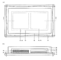
- FIG. 1A and 1B are diagrams illustrating a schematic structure of a solid lithium ion battery according to an embodiment of the present invention.
- FIG. 1A is a plan view
- FIG. 1B is a cross-sectional view taken along line XX
- FIG. C is a YY sectional view.
- the solid lithium ion battery includes a positive electrode side current collector film 30, a positive electrode active material film 40, a solid electrolyte film 50, a negative electrode potential forming layer 64, and a negative electrode side current collector film 70 in order. It has a laminate formed on (organic insulating substrate) 10.
- An overall protective film 80 made of, for example, an ultraviolet curable resin is formed so as to cover the entire laminate.
- the film configuration of the battery shown in FIG. 1 is substrate / positive electrode side current collector film / positive electrode active material film / solid electrolyte film / negative electrode potential forming layer / negative electrode side current collector film / overall protective film.
- a plurality of the above-described laminates may be sequentially laminated on the substrate (organic insulating substrate) 10, electrically connected in series, and covered with the entire protective film 80. it can. Further, a plurality of the above-described laminates may be formed side by side on the substrate (organic insulating substrate) 10, electrically connected in parallel or in series, and covered with the entire protective film 80. .
- the negative electrode side current collector film 70, the negative electrode potential forming layer 64, the solid electrolyte film 50, the positive electrode active material film 40, and the positive electrode side current collector film 30 are arranged in this order.
- the film configuration of the battery can be substrate / negative electrode side current collector film / negative electrode potential forming layer / solid electrolyte film / positive electrode active material film / positive electrode side current collector film / overall protective film.
- FIG. 2A and 2B are diagrams for explaining a schematic structure of a solid lithium ion battery according to an embodiment of the present invention.
- FIG. 2A is a plan view and
- FIG. 2B is a cross-sectional view taken along line XX.
- FIG. 2A and 2B are diagrams for explaining a schematic structure of a solid lithium ion battery according to an embodiment (part 2) of the present invention.
- FIG. 2A is a plan view and
- FIG. 2B is a cross-sectional view taken along line XX. It is.
- the solid lithium ion battery includes a laminate including a positive electrode side current collector film 30 and a positive electrode active material film 40 formed on a substrate (organic insulating substrate) 10, and a negative electrode side current collector. It has a laminated body composed of the electric conductor film 70 and the negative electrode potential forming layer 64.
- a solid electrolyte film 50 is formed so as to cover the whole of the above two stacked bodies formed side by side on the substrate (organic insulating substrate) 10, and, for example, an ultraviolet ray is formed so as to cover the whole of the solid electrolyte film 50.
- An overall protective film 80 made of a cured resin is formed.
- FIG. 3A and 3B are diagrams for explaining a schematic structure of a solid lithium ion battery according to an embodiment of the present invention.
- FIG. 3A is a plan view
- FIG. 3B is an XX sectional view
- FIG. c) is a YY sectional view.
- the solid lithium ion battery has an inorganic insulating film 20 formed on the surface of a substrate (organic insulating substrate) 10, and a positive current collector film 30 on the inorganic insulating film 20.
- the positive electrode active material film 40, the solid electrolyte film 50, the negative electrode potential forming layer 64, and the negative electrode side current collector film 70 have a laminated body formed in order.
- An overall protective film 80 made of, for example, an ultraviolet curable resin is formed so as to cover the entire laminate and the inorganic insulating film 20.
- the film structure of the battery shown in FIG. 3 is substrate / inorganic insulating film / positive electrode side current collector film / positive electrode active material film / solid electrolyte film / negative electrode potential forming layer / negative electrode side current collector film / overall protective film.
- a plurality of the laminated bodies described above may be sequentially laminated on the inorganic insulating film 20, electrically connected in series, and covered with the entire protective film 80.
- a plurality of the above-described stacked bodies may be formed side by side on the inorganic insulating film 20, electrically connected in parallel or in series, and covered with the entire protective film 80.
- the negative electrode current collector film 70, the negative electrode potential forming layer 64, the solid electrolyte film 50, the positive electrode active material film 40, and the positive electrode side current collector film 30 are sequentially formed. It can also be formed on top. That is, the battery film configuration can be substrate / inorganic insulating film / negative electrode side current collector film / negative electrode potential forming layer / solid electrolyte film / positive electrode active material film / positive electrode side current collector film / overall protective film. .
- FIG. 4A and 4B are diagrams for explaining a schematic structure of a solid lithium ion battery according to an embodiment of the present invention.
- FIG. 4A is a plan view and
- FIG. 4B is a cross-sectional view taken along line XX.
- the solid lithium ion battery has an inorganic insulating film 20 formed on the surface of a substrate (organic insulating substrate) 10, and on the inorganic insulating film 20, a positive current collector film 30. And a positive electrode active material film 40, and a negative electrode side current collector film 70 and a negative electrode potential forming layer 64.
- a solid electrolyte film 50 is formed so as to cover the whole of the two laminated bodies formed side by side on the inorganic insulating film 20, and, for example, an ultraviolet curable resin is used so as to cover the whole of the solid electrolyte film 50.
- An overall protective film 80 is formed.
- a plurality of sets of the above two laminates may be formed side by side on the inorganic insulating film 20, electrically connected in parallel or in series, and covered with the entire protective film 80. it can.
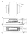
- FIG. 5 is a diagram for explaining the outline of the manufacturing process of the solid lithium ion battery in the embodiment of the present invention.
- 5A shows a manufacturing process of the solid lithium ion battery shown in FIG. 1
- FIG. 5B shows a manufacturing process of the solid lithium ion battery shown in FIG.
- the positive electrode side current collector film 30 As shown in FIG. 5A, first, on the substrate (organic insulating substrate) 10, the positive electrode side current collector film 30, the positive electrode active material film 40, the solid electrolyte film 50, the negative electrode potential forming layer 64, the negative electrode side.
- the current collector film 70 is sequentially formed to form a stacked body.
- an entire protective film 80 made of, for example, an ultraviolet curable resin is formed on the substrate (organic insulating substrate) 10 so as to cover the entire laminate. In this way, the solid lithium ion battery shown in FIG. 1 can be produced.
- an inorganic insulating film 20 is formed on the surface of the substrate (organic insulating substrate) 10.
- a positive electrode side current collector film 30, a positive electrode active material film 40, a solid electrolyte film 50, a negative electrode potential forming layer 64, and a negative electrode side current collector film 70 are sequentially formed and laminated on the inorganic insulating film 20.
- the body is formed.
- an overall protective film 80 made of, for example, an ultraviolet curable resin is formed on the substrate (organic insulating substrate) 10 so as to cover the entire laminate and the inorganic insulating film 20. In this way, the solid lithium ion battery shown in FIG. 3 can be produced.
- the manufacturing process of the solid lithium ion battery shown in FIG. 2 is as follows. First, a laminate in which a positive electrode side current collector film 30 and a positive electrode active material film 40 are sequentially formed on a substrate (organic insulating substrate) 10, and a negative electrode side current collector film 70 and a negative electrode potential forming layer 64. Are sequentially formed and formed in parallel.
- the solid electrolyte membrane 50 is formed so as to cover the whole of the two laminated bodies formed side by side on the substrate (organic insulating substrate) 10.
- an entire protective film 80 made of, for example, an ultraviolet curable resin is formed on the inorganic insulating film 20 so as to cover the entire solid electrolyte film 50.
- the manufacturing process of the solid lithium ion battery shown in FIG. 4 is as follows. First, the inorganic insulating film 20 is formed on the surface of the substrate (organic insulating substrate) 10. Next, a laminate in which the positive electrode side current collector film 30 and the positive electrode active material film 40 are sequentially formed on the inorganic insulating film 20, and the negative electrode side current collector film 70 and the negative electrode potential forming layer 64 are sequentially formed. The formed laminates are formed side by side.
- the solid electrolyte membrane 50 is formed so as to cover the whole of the two laminated bodies formed side by side on the inorganic insulating film 20.
- an entire protective film 80 made of, for example, an ultraviolet curable resin is formed on the inorganic insulating film 20 so as to cover the entire solid electrolyte film 50.
- the following materials can be used as materials constituting the solid lithium ion battery.
- lithium phosphate (Li 3 PO 4), nitrogen Li 3 PO 4 N x (typically with the addition of lithium phosphate (Li 3 PO 4), are called LiPON.
- LiBO 2 N x , Li 4 SiO 4 —Li 3 PO 4 , Li 4 SiO 4 —Li 3 VO 4, etc. can be used.
- a solid electrolyte material having high ion conductivity since the movement distance of lithium ions becomes long, it is preferable to use a solid electrolyte material having high ion conductivity.
- the material that can form the positive electrode active material film 40 may be any material that can easily release and adsorb lithium ions and can release and occlude many lithium ions.
- examples of such materials include lithium-manganese oxides such as LiMnO 2 (lithium manganate), LiMn 2 O 4 , and Li 2 Mn 2 O 4 , and lithium-cobalts such as LiCoO 2 (lithium cobaltate) and LiCo 2 O 4.
- LiNiO 2 lithium nickelate
- LiNi 2 O 4 lithium-manganese-cobalt oxides
- LiMnCoO 4 Li 2 MnCoO 4
- Li 4 Ti 5 O 12 LiTi 2 O lithium, such as 4 - titanium oxide, other, Li 2 CuO 2, LiCuO 2 , LiV0 2, LiV 2 O 4, LiCrO 2, LiFeO 2, LiTiO 2, LiScO 2, LiYO 2, LiMnCrO 4, LiNiVO 4, LiCoVO 4 , LiFePO 4 (lithium iron phosphate), LiCuPO 4, LiNiPO 4, L CoPO 4, LiMnPO 4, Li 2 NiPO 4 F, Li 2 CoPO 4 F, Li 2 MnPO 4 F, Li 2 FePO 4 F, LiVOPO 4, Li 3 V 2 (PO 4) 3, Li 2 MnSiO 4, Li 2 FeSiO 4 , Li 2 CoSiO 4 , Li 2 NiSiO 4 , Li 2 NiSiO 4 , Li 2 NiSiO
- the negative electrode potential forming layer 64 is selected and used from the materials described above that can form the positive electrode active material film 40.
- the positive electrode side current collector film 30 and the negative electrode side current collector 70 As materials constituting the positive electrode side current collector film 30 and the negative electrode side current collector 70, Cu, Mg, Ti, Fe, Co, Ni, Zn, Al, Ge, In, Au, Pt, Ag, Pd, etc., or An alloy containing any of these can be used.
- the material constituting the inorganic insulating film 20 may be any material that can form a film having low moisture absorption and moisture resistance.
- a material an oxide or nitride or sulfide of Si, Cr, Zr, Al, Ta, Ti, Mn, Mg, Zn, or a mixture thereof can be used. More specifically, Si 3 N 4 , SiO 2 , Cr 2 O 3 , ZrO 2 , Al 2 O 3 , TaO 2 , TiO 2 , Mn 2 O 3 , MgO, ZnS, or a mixture thereof is used. can do.
- Each of the solid electrolyte film 50, the positive electrode active material film 40, the negative electrode potential forming layer 64, the positive electrode side current collector film 30, the negative electrode side current collector 70, and the inorganic insulating film 20 described above is formed by sputtering or electron beam evaporation. It can form by dry processes, such as a method and a heat evaporation method.
- polycarbonate (PC) resin substrate fluororesin substrate
- PET polyethylene terephthalate
- PBT polybutylene terephthalate
- PI polyimide
- PA polyamide
- PES polysulfone
- PES polyethersulfone
- PES polyphenylene sulfide
- PEEK polyetheretherketone
- the material constituting the entire protective film 80 may be any material that can form a film having low moisture absorption and moisture resistance.
- a material an acrylic ultraviolet curable resin, an epoxy ultraviolet curable resin, or the like can be used.
- the whole protective film can also be formed by vapor deposition of a parylene resin film.
- FIG. 6 is a diagram illustrating the configuration of each layer of the solid lithium ion battery in the examples and comparative examples of the present invention.
- Example 1 A solid lithium ion battery having the configuration shown in FIG. 1 was prepared.
- a polycarbonate (PC) substrate having a thickness of 1.1 mm was used as the substrate 10.
- a substrate made of a glass material, acrylic, or the like can be used as long as it is sufficiently flat depending on the film thickness of the battery without conductivity and having a smooth surface.
- An Si 3 N 4 film having a thickness of 200 nm was formed as an inorganic insulating film 20 on the entire surface of the substrate 10.
- a metal mask is disposed on the inorganic insulating film 20, and the positive electrode side current collector film 30, the positive electrode active material film 40, the solid electrolyte film 50, the negative electrode potential forming layer 64, and the negative electrode side current collector.
- the body film 70 was formed in this order to form a laminate. However, this order is the opposite order, that is, the negative electrode side current collector film 70, the negative electrode potential forming layer 64, the solid electrolyte film 50, the positive electrode active material film 40, and the positive electrode side current collector film 30 in this order. It can also be deposited on top.
- a 500 ⁇ m stainless steel mask is used as the metal mask, but a pattern can also be formed using a lithography technique. In any case, all the films constituting the laminate are formed on the inorganic insulating film.
- Ti was used as the positive electrode side and negative positive electrode side current collector films 30 and 70, and the film thickness was 100 nm or 200 nm. As long as the positive electrode side and negative positive electrode side current collector films 30 and 70 are conductive and have excellent durability, other materials can be used as well. Specifically, Au, Pt, Cu or the like, or a metal material containing these alloys is used. This metal material may contain an additive for enhancing durability and conductivity.
- LiMn 2 O 4 was used as the positive electrode active material film 40, and the film thickness was 125 nm.
- the film formation method of the positive electrode active material film 40 is based on a sputtering method, and the substrate 10 is in an amorphous state because it is formed at a room temperature and without post-annealing.
- XRD Shiazu XRD-6000
- Example 1 does not depend on the state of the positive electrode active material film 40, and even if it is crystallized, the same characteristics as in Example 1 or better than Example 1 can be obtained. Needless to say, the effects of the present invention can be obtained.
- the positive electrode active material film 40 can be formed of other materials, and well-known materials such as LiCoO 2 , LiFePO 4 , and LiNiO 2 can also be used.
- the film thickness of the positive electrode active material film 40 there is nothing specially noted except that the thicker the battery capacity is, the capacity in Example 1 is about 7 ⁇ Ah / cm 2 (see FIG. 7 described later). Thus, the amount is sufficient to show the effects of the present invention.
- the film thickness of the positive electrode active material film 40 can be adjusted according to the application / use.
- Example 1 it goes without saying that further excellent characteristics can be obtained if the positive electrode active material film 40 is annealed.
- Li 3 PO 4 N x was used for the solid electrolyte membrane 50.
- the deposition conditions of the solid electrolyte film 50 are also the conditions in which the temperature of the substrate 10 during sputtering is room temperature and no post-annealing, and the formed solid electrolyte film 50 is in an amorphous state. Since the composition x of nitrogen in the formed solid electrolyte membrane 50 is based on reactive sputtering of nitrogen in the sputtering gas, the exact numerical value is unknown, but is considered to be the same as in Non-Patent Document 1.
- Example 1 it is clear that the same effect can be obtained even when other solid electrolyte membrane materials are used, and well-known materials such as LiBO 2 N x , Li 4 SiO 4 —Li 3 PO 4 are used. Li 4 SiO 4 —Li 3 VO 4 or the like can also be used.
- the film thickness of the solid electrolyte membrane 50 it is necessary to have sufficient insulation, and if it is too thin, there is a possibility of causing a short circuit in the initial stage or charging / discharging process.
- the substrate current collector material, film forming method, and charge / discharge speed, there are cases where a thicker thickness is more preferable in terms of durability.
- the thickness of the solid electrolyte membrane 50 is too large, for example, if it is 500 nm or more, the ionic conductivity of the solid electrolyte membrane 50 is often lower than that of the liquid electrolyte.
- the solid electrolyte film 50 is formed by sputtering, if the film thickness is too thick, the sputtering time is increased and the tact time is increased, so that the sputtering chamber must be multi-channeled. It is not preferable.
- the thickness of the solid electrolyte membrane 50 was 145 nm.
- a material capable of forming the positive electrode active material film 40 for the negative electrode potential forming layer 64 or a material having a close potential.
- LiMn 2 which is the same material as the positive electrode active material film 40 is used.
- An example using O 4 is shown.
- the film thickness of the negative electrode potential forming layer 64 is 6 nm.
- the negative electrode side current collector film 70 and the positive electrode side current collector film 30 were made of Ti and the film thickness was 200 nm.
- the entire protective film 80 was formed using an ultraviolet curable resin.
- the entire protective film 80 functions as a protective film against moisture intrusion from the surface opposite to the substrate 10.
- the entire protective film 80 appropriately follows and covers the surface of the battery according to the expansion / contraction due to charge / discharge, thereby preventing the entry of harmful substances such as water and oxygen and making it difficult to cause an electrical short circuit. Admitted.
- many foam defects having a size of 100 ⁇ m or more were generated on the surface in about one week, short-circuited, and no longer functioned as a battery. Therefore, the entire protective film 80 functions as a protective film. At the same time, it is protected from scratches during handling.
- the UV curable resin used for forming the entire protective film 80 the one with model number SK3200 manufactured by Sony Chemical & Information Device was used, but other UV curable resin such as model number SK5110 manufactured by the company, for example, should also be used. The same effect can be expected.
- the material used for forming the entire protective film is particularly preferably a material having a high water-resistant protective effect.
- the battery film structure is polycarbonate substrate / Si 3 N 4 (200 nm) / Ti (100 nm) / LiMn 2 O 4 (125 nm) / Li 3 PO 4 N x (145 nm) / LiMn 2 O 4 ( 6 nm) / Ti (200 nm) / ultraviolet curable resin (20 ⁇ m) (see FIG. 6A).
- each of the films constituting the battery is formed by sputtering.
- methods such as vapor deposition, plating, and spray coating can be used.
- LiMn 2 O 4 and Li 3 PO 4 N x SMO-01 special model manufactured by ULVAC, Inc. was used.
- the target size is ⁇ 4 inches.
- the sputtering conditions for each layer are as follows.
- the charge / discharge curve was measured using a Keithley® 2400, and the charge / discharge rate was 1 C for all (current value corresponding to completion of charge / discharge in one hour).
- the charge / discharge current value in Example 1 is 8 ⁇ A.
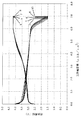
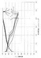
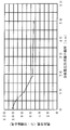
- FIG. 7 is a diagram showing a charge / discharge curve of the solid lithium ion battery in Example 1 of the present invention, in which the horizontal axis represents the charge / discharge capacity ( ⁇ Ah / cm 2 ) and the vertical axis represents the battery voltage (V).
- the results shown in FIG. 7 indicate that charging / discharging in repeated charging / discharging is performed very well. Since the material constituting the positive electrode active material film is not crystallized, the obtained battery voltage is slightly lower as compared with a normal Li ion battery, but can be driven in a range of 2.5 V or more. Furthermore, as soon as the discharge is completed, the battery voltage is drastically decreased, which is an ideal behavior as a battery. This is considered to be an effect of the negative electrode potential forming layer 64.
- the potential is ideally reduced to 0 at the same time that Li is completely discharged without being affected by changes in potential due to the surface state of the negative electrode side current collector. It was shown to decline.
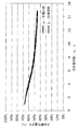
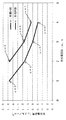
- FIG. 8 is a diagram showing the charge / discharge cycle characteristics of the solid lithium ion battery in Example 1 of the present invention.
- FIG. 8 shows the experimental results of repeating charge / discharge for about 30 cycles, and shows that the battery performance is very little deteriorated within this experimental range, and good repeated charge / discharge characteristics are obtained.
- Such a good characteristic in which the capacity is not deteriorated at all or the capacity is slightly increased in the initial stage of charging / discharging is realized by the configuration of the present invention.
- the thin film Li battery having the configuration according to Example 1 has good discharge voltage characteristics and repeated charge / discharge characteristics.
- LiCoO 2 , LiFePO 4 , LiNiO 2, or the like can be used as a material that can form the positive electrode active material film 40 or a material that is close to the standard electrode potential of the positive electrode active material.
- the range will be described. Although the result of Example 1 shows that it can be driven at a voltage of 2.5 V or more, the battery is preferably used in a range of 0.5 V or more.
- the standard electrode potential is different from the standard electrode potential of the positive electrode active material film 40 using a material different from that of the positive electrode active material film 40 as the negative electrode potential forming layer 64
- Battery drive will be 0.5V or less.
- the standard electrode potential is 2 V or higher and the standard electrode potential is high, the voltage of the battery exceeds 4.5 V.
- the material of the negative electrode potential forming layer 64 is preferably such that the difference between the standard electrode potential and the standard electrode potential of the positive electrode active material is 2 V or less.
- Comparative Example 1 The result in the case of the battery which has the conventional structure using a negative electrode active material is shown as a comparative example.
- ITO having a film thickness of 20 nm is used as the negative electrode active material.
- the film structure of the produced battery was polycarbonate substrate / Si 3 N 4 (200 nm) / Ti (100 nm) / LiMn 2 O 4 (125 nm) / Li 3 PO 4 N x (145 nm) / ITO (20 nm) / Ti (200 nm) ) / UV curable resin (20 ⁇ m) (see FIG. 6B).
- An ITO film C-3103 is used for the ITO film formation, and the target size is ⁇ 6 inches.
- the sputtering conditions are as follows.
- Target composition ITO (In 2 O 3 90 wt.% + SnO 2 10 wt.%)
- Sputtering gas Ar 120 sccm + (Ar 80% + O 2 20% mixed gas) 30 sccm, 0.10 Pa
- Sputtering power 1000 W (DC)
- the other films constituting the battery were formed in the same manner as in Example 1, and the measurement conditions of the battery characteristics were the same as in Example 1.
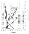
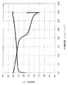
- FIG. 9 is a diagram showing a charge / discharge curve of a solid lithium ion battery in Comparative Example 1 of the present invention, in which the horizontal axis and the vertical axis are the same as those shown in FIG. The meanings of even numbers and odd numbers n are the same as in FIG.
- FIG. 10 is a diagram showing the charge / discharge cycle characteristics of the solid lithium ion battery in Comparative Example 1 of the present invention.
- the horizontal axis and the vertical axis are the same as those shown in FIG.
- the battery voltage rapidly decreases immediately after the start of discharge, and the battery voltage gradually decreases until the discharge is completed. It can be seen that sufficient capacity (nearly 80% of the initial discharge capacity) cannot be obtained unless the battery voltage is lowered to 0.5V.
- the repeated charge / discharge characteristics are worse than the repeated charge / discharge characteristics of the battery according to Example 1 shown in FIG. 8, and the battery capacity drops to less than 60% in 8 repetitions. is doing.
- Example 1 in the conventional battery configuration of Comparative Example 1, the thin film battery formed by the sputtering thin film cannot obtain good characteristics, and the negative electrode active material Instead, it was shown that it is effective to provide the negative electrode potential forming layer 64 according to the present invention.
- Example 2 An example in which the film thickness of the negative electrode potential forming layer 64 is 13 nm is shown.
- the other films constituting the battery were formed in the same manner as in Example 1, and the measurement conditions for battery characteristics were the same as in Example 1.
- the film structure of the battery was polycarbonate substrate / Si 3 N 4 (200 nm) / Ti (100 nm) / LiMn 2 O 4 (125 nm) / Li 3 PO 4 N x (145 nm) / LiMn 2 O 4 (13 nm) / Ti ( 200 nm) / ultraviolet curable resin (20 ⁇ m) (see FIG. 6A).
- FIG. 11 is a diagram showing a charge / discharge curve of a solid lithium ion battery in Example 2 of the present invention, and the horizontal axis and the vertical axis are the same as those shown in FIG. 7, and are attached to the charge / discharge curve.
- the meanings of even numbers and odd numbers n are the same as in FIG.
- the drive voltage is maintained at 2.5 V or higher, and the repeated charge / discharge characteristics are good because the charge / discharge capacity increases with the number of charge / discharge cycles.
- the battery capacity was very low, which was about 30% of the capacity expected from the theoretical capacity of the positive electrode active material (utilization efficiency described later). It is considered that the battery capacity is low because Li is excessively taken into the negative electrode potential forming layer 64 and does not return to the positive electrode active material film 40 during discharge.
- the film quality of the negative electrode potential forming layer 64 by the film formation method of this Example 2 (a film formation method that is a sputtering thin film formed at room temperature and does not perform post-annealing), if the film thickness exceeds 13 nm, the capacity is further increased. From the theoretical capacity of the material, the battery capacity is reduced to about 30% or less of the expected capacity. In consideration of practicality, the battery capacity is desirably about 30% or more of the capacity expected from the theoretical capacity of the positive electrode active material, and the film thickness of the negative electrode potential forming layer 64 is preferably 13 nm or less.
- Example 3 An example in which the film thickness of the negative electrode potential forming layer 64 is 10 nm is shown.
- the other films constituting the battery were formed in the same manner as in Example 1, and the measurement conditions for battery characteristics were the same as in Example 1.
- the film structure of the battery was polycarbonate substrate / Si 3 N 4 (200 nm) / Ti (100 nm) / LiMn 2 O 4 (125 nm) / Li 3 PO 4 N x (145 nm) / LiMn 2 O 4 (10 nm) / Ti ( 200 nm) / ultraviolet curable resin (20 ⁇ m) (see FIG. 6A).
- FIG. 12 is a diagram showing a charge / discharge curve of a solid lithium ion battery in Example 3 of the present invention, and the horizontal axis and the vertical axis are the same as those shown in FIG. The meanings of even numbers and odd numbers n are the same as in FIG.
- the drive voltage is maintained at 2.5 V or more, and the charge / discharge capacity is increased and the charge / discharge capacity is good with the number of charge / discharge cycles, and the charge / discharge capacity is the case of Example 2 (FIG. 11).
- the value is larger than Therefore, the film thickness of the negative electrode potential forming layer 64 is more preferably 10 nm or less.
- the film thickness of the negative electrode potential forming layer is increased, the impedance is increased and the charge / discharge capacity is reduced. Therefore, when LiMn 2 O 4 is used, the film thickness is set to 10 nm or less, more preferably 5 nm or less. Is good. However, the smaller the film thickness, the better the charge / discharge capacity. On the other hand, the film thickness of 5 nm decreases the smoothness of the film and decreases the durability and yield. From the viewpoint of durability and yield, the negative electrode potential is formed. A thicker layer is preferred.
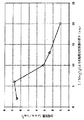
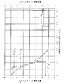
- FIG. 13 is a diagram for explaining the relationship between the discharge capacity of the solid lithium ion battery and the thickness of the negative electrode potential forming layer in the example of the present invention, and the horizontal axis represents the thickness of the negative electrode potential forming layer of LiMn 2 O 4 , The vertical axis represents the discharge capacity ( ⁇ Ah / cm 2 ).
- FIG. 13 shows the capacity (battery capacity) that can be used when the battery voltage reaches 2.5 V in the charging curve during the tenth discharge. From the results shown in FIG. 13, when the battery capacity is maximized, that is, when the film thickness of the negative electrode potential forming layer is 6 nm (referred to as the maximum capacity), the film thickness of the negative electrode potential forming layer is 100%.
- the battery capacities (referred to as relative battery capacities) in the case of 2 nm, 3 nm, 10 nm, 13 nm, and 20 nm are 95.6%, 97.1%, 47.1%, respectively, as shown in FIG. 35.3% and 16.2%.
- the capacity can be 15% or more of the maximum capacity if the thickness of the negative electrode potential forming layer is 2 nm or more and 20 nm or less. . Further, if the thickness of the negative electrode potential forming layer is 2 nm or more and 13 nm or less, the capacity can be 35% or more of the maximum capacity, and if the thickness of the negative electrode potential forming layer is 3 nm or more and 10 nm or less, If the capacity can be 45% or more of the maximum capacity and the thickness of the negative electrode potential forming layer is 3 nm or more and 6 nm or less, the capacity can be almost the maximum capacity.
- the discharge capacity of the solid lithium ion battery varies depending on the film thickness of the negative electrode potential forming layer, and when the film thickness of the negative electrode potential forming layer is 2 nm, the charge is almost the same as when the film thickness is 6 nm.
- the discharge characteristics are shown, and the discharge capacities show substantially the same value.
- the discharge capacity decreases.
- the thickness exceeds 13 nm, the capacity decreases to about 30% or less of the expected discharge capacity from the theoretical capacity of the positive electrode active material. To do.
- the discharge capacities are described later. As shown in FIG. 20, it is 83.7%, 87.5%, 41.2%, 30.9%, and 14.2% of the capacity expected from the theoretical capacity of the positive electrode active material of 7.77 ⁇ Ah / cm 2. (It is the utilization efficiency described later.)
- the battery capacity is desirably about 30% or more of the capacity expected from the theoretical capacity of the positive electrode active material
- the film thickness of the negative electrode potential forming layer 64 is preferably 2 nm or more and 13 nm or less.
- the negative electrode potential forming layer 64 has a film thickness of less than 3 nm, the stability of the film thickness is reduced. Therefore, in order to form the negative electrode potential forming layer 64 in a stable state and ensure the mass productivity of the battery, it is desirable that the negative electrode potential forming layer 64 has a thickness of 3 nm or more. .
- the thickness of the negative electrode potential forming layer 64 is preferably 3 nm or more and 10 nm or less, and the film thickness is 3 nm or more and 6 nm or less. Is more preferable.
- Comparative Example 2 A comparative example prepared by the same film forming method as in Example 1 without using the negative electrode potential forming layer 64 is shown.
- the film configuration of the battery in Comparative Example 2 is exactly the same as in Example 1 except that the negative electrode potential forming layer 64 is not formed.
- the film structure of the battery in Comparative Example 2 was polycarbonate substrate / Si3N4 (200 nm) / Ti (100 nm) / LiMn 2 O 4 (125 nm) / Li 3 PO 4 N x (145 nm) / Ti (200 nm) / UV curable resin ( 20 ⁇ m) (see FIG. 6B).
- the film structure of this battery is simply a film structure of a battery without a negative electrode active material film, and is basically the same as that of Non-Patent Document 2.
- the other films constituting the battery were formed in the same manner as in Example 1, and the conditions for measuring battery characteristics were the same as in Example 1.
- FIG. 14 is a diagram showing a charge / discharge curve of a solid lithium ion battery in Comparative Example 2 of the present invention, and the horizontal axis and the vertical axis are the same as those shown in FIG. The meanings of even numbers and odd numbers n are the same as in FIG.
- FIG. 15 is a diagram showing charge / discharge cycle characteristics of a solid lithium ion battery in Comparative Example 2 of the present invention.
- the horizontal axis in FIG. 15 is the same as that shown in FIG. 8, and the vertical axis in FIG. 15 shows the charge / discharge capacity ( ⁇ Ah / cm 2 ) shown in FIG.
- the negative electrode potential forming layer 64 used in the present invention has good battery characteristics by minimizing the diffusion of Li into the negative electrode current collector film 70 while having conductivity. Furthermore, since the negative electrode potential forming layer 64 is thin, the negative electrode potential forming layer 64 itself does not function as a negative electrode and contributes to the formation of an excessive layer of Li. is there.
- the negative electrode potential forming layer 64 is a layer provided to form a negative electrode potential at the time of charging, but has a function of suppressing the diffusion of Li to the negative electrode side current collector and protecting the negative electrode side current collector. It is also a negative electrode current collector protective film.
- Comparative Example 2 when 10 battery samples were formed, 10 films were formed at the same time. However, only one charge / discharge curve shown in FIG. 9 was obtained, and the others were short-circuited during initial charging. As a result, the battery was defective. That is, when a battery having a configuration as in Comparative Example 2 is produced, the yield is very poor. On the other hand, the battery having the configuration of Example 1 has a yield of almost 100%, high productivity, and very high stability.
- Example 1 Example 2, and Example 3 described above, the solid-state lithium ion battery in which the negative electrode potential forming layer and the positive electrode active material film are made of LiMn 2 O 4 has been described.
- the film thickness of the negative electrode potential forming layer (negative electrode side current collector protective film) formed of LiCoO 2 can be increased to 20 nm, and includes a negative electrode potential forming layer having a film thickness of 2 nm or more and 20 nm or less.
- the solid lithium ion battery has high durability and good charge / discharge characteristics.
- Example 4 An example of a solid lithium ion battery in which a negative electrode potential forming layer and a positive electrode active material film are each composed of LiCoO 2 is shown. Each film constituting the battery was formed in the same manner as in Example 1, and the charge / discharge curve of the battery was measured in the same manner as in Example 1.
- the formation conditions of the LiCoO 2 film are as follows.
- Target composition LiCoO 2 Target size: ⁇ 4 inch sputtering gas: (Ar 80% + O 2 20%) mixed gas, 20 sccm, 0.20 Pa Sputtering power: 300W (RF)
- the sputtering time was adjusted to obtain a desired film thickness.
- a thin film battery was prepared by setting the film thickness of the positive electrode active material to 180 nm, the film thickness of the solid electrolyte film to 480 nm, and the film thickness t of the negative electrode potential forming layer to 5 nm, 10 nm, 20 nm, and 50 nm.
- FIG. 16 is a graph showing the relationship between the charge / discharge characteristics of the solid lithium ion battery and the film thickness of the negative electrode potential forming layer in Example 4 of the present invention, where the horizontal axis represents the charge / discharge capacity ( ⁇ Ah / cm 2 ) and the vertical axis. The axis indicates the battery voltage (V). Since Li is deposited during the charge / discharge process, this Li metal is used as a negative electrode, and the battery voltage is at a potential based on the negative electrode (Li metal).
- curves 1a, 2a, 3a, 4a, and 5a indicate charge curves
- curves 1b, 2b, 3b, 4b, and 5b indicate discharge curves, respectively.
- Curves (1a, 1b), curves (2a, 2b), curves (3a, 3b), curves (4a, 4b), and curves (5a, 5b) have a negative electrode potential forming layer thickness of 1 nm, 5 nm, 10 nm, respectively. , 19 and 50 nm, the charge curve and the discharge curve measured by the battery.
- the charging curve shows the ninth charging curve
- the discharging curve shows the tenth discharging curve.
- the capacity (battery capacity) that can be used when the battery voltage reaches 1.5 V during discharging is such that the film thickness of the negative electrode potential forming layer is 1 nm, 5 nm, 10 nm, 19 nm, and 50 nm. In the battery, they are 12.8 ⁇ Ah / cm 2 , 12.0 ⁇ Ah / cm 2 , 9.6 ⁇ Ah / cm 2 , 7.1 ⁇ Ah / cm 2 , and 6.8 ⁇ Ah / cm 2 , respectively.
- the battery capacity increases as the thickness of the negative electrode potential forming layer decreases.
- the film thickness of the negative electrode potential forming layer was 1 nm, it was only the first few cycles that a charge / discharge curve as shown in FIG. 16 could be measured. This is presumably because the protective function for the negative electrode current collector film was insufficient because the negative electrode potential forming layer was too thin.
- the film thickness of the negative electrode potential forming layer was 2 nm, the charge / discharge characteristics were almost the same as when the film thickness was 1 nm, but the charge / discharge stability was improved and initial charge / discharge was possible. Yield was over 90%.
- the film thickness of the negative electrode potential forming layer is preferably 2 nm or more. Furthermore, when the film thickness of the negative electrode potential forming layer was 5 nm or more, the capacity was hardly deteriorated by repeated charge and discharge. Therefore, the film thickness of the negative electrode potential forming layer is more preferably 5 nm or more.
- the film thickness of the negative electrode potential forming layer increases, the behavior of the low voltage region of the discharge curve changes slightly, the battery capacity gradually decreases, and in a battery where the film thickness of the negative electrode potential forming layer is 20 nm. Although the battery capacity decreases to about 7 ⁇ A / cm 2, there is no significant difference in the battery capacity range that can be used in the region of 2.5 V or more in a battery having a negative electrode potential forming layer thickness of 20 nm or more.
- the film thickness of the negative electrode potential forming layer is 20 nm or less, the battery capacity reduction is acceptable, practical, sufficient protection function for the negative electrode current collector film, and battery capacity reduction. Therefore, it can be said that the battery has good characteristics.
- the thickness of the negative electrode potential forming layer exceeds 20 nm, the behavior of a potential higher than 2.5 V deteriorates, and as shown by the curves 5a and 5b of the battery having a negative electrode potential forming layer thickness of 50 nm, 2
- the range that can be driven at a high voltage higher than 5 V is drastically reduced. Therefore, it is not preferable that the film thickness of the negative electrode potential forming layer exceeds 20 nm.
- FIG. 17 is a diagram for explaining the relationship between the discharge capacity of the solid lithium ion battery and the thickness of the negative electrode potential forming layer in Example 4 of the present invention.
- the vertical axis indicates the battery capacity by a value (referred to as “utilization efficiency”) obtained by converting the theoretical capacity calculated from the film thickness of the positive electrode active material to 100%, and the horizontal axis indicates the thickness of the negative electrode potential forming layer. (Nm).
- the utilization efficiency is a value (expressed as a percentage) obtained by dividing the capacity (battery capacity) that can be utilized when the battery voltage reaches 1.5 V during discharging by the theoretical capacity calculated from the film thickness of the positive electrode active material. .)
- the density of LiCoO 4 is 5.16 g / cm 3 and the discharge capacity of the battery in which the film thickness of the negative electrode potential forming layer is 1 nm, 5 nm, 10 nm, 19 nm, and 50 nm in FIG. 17 is shown in FIG. As shown, the capacity is 100.8%, 94.4%, 75.6%, 55.9% and 53.5% of the capacity expected from the theoretical capacity of 12.7 ⁇ Ah / cm 2 of the positive electrode active material.
- the utilization efficiency is 2 nm, 6 nm, 10 nm, 13 nm, and 20 nm. In each case, it decreases to about 100%, about 95%, about 90%, about 80%, and about 60%.
- the thickness of the negative electrode potential forming layer is preferably 2 nm or more and 10 nm or less, and the utilization efficiency can be about 90% or more.
- the negative electrode potential forming layer is thicker, but the negative electrode potential forming layer has a film thickness of 2 nm or more and 20 nm or less. If it is in the range, the utilization efficiency can be about 80% or more, and it can be said that the decrease in battery capacity is also acceptable.
- the film thickness of the negative electrode potential forming layer exceeds 20 nm, the result is that the battery capacity obtained when cutting at 1.5 V in FIG. 17 is not so different from the case where the film thickness of the negative electrode potential forming layer is 20 nm. Although obtained, it is not preferable that the film thickness of the negative electrode potential forming layer exceeds 20 nm in light of the results of FIG. 16 in terms of securing a range that can be driven at a high voltage higher than 2.5V. Is clear. Therefore, the upper limit of the film thickness is 20 nm.
- the optimum film thickness range is different from that in the above-described Examples 1 to 3 in which the negative electrode potential forming layer is composed of LiMn 2 O 4 .
- the conductivities of LiCoO 2 and LiMn 2 O 4 are about 10 ⁇ 2 S / cm and about 10 ⁇ 6 S / cm, respectively.
- the negative electrode potential forming layer (negative electrode current collector protective film) functions well even when the film thickness is thicker than 20 nm.
- the optimum film thickness range varies depending on the ion conductivity of the formation layer.
- each film thickness of the anode potential formation layer is 1 nm, 5 nm, 10 nm, 19 nm, relative to 50nm, 12.8 ⁇ Ah / cm 2, 12.0 ⁇ Ah / cm 2, 9.6 ⁇ Ah / cm 2, 7.1 ⁇ Ah / Cm 2 and 6.8 ⁇ Ah / cm 2 .
- the film of the negative electrode potential forming layer is 100%.
- Battery capacities (referred to as relative battery capacities) when the thicknesses are 2 nm, 3 nm, 5 nm, 6 nm, 10 nm, 13 nm, and 20 nm are 98.4%, 96.9%, 93.8%, 89.8%, 75%, 68.8% and 55.4%.
- the negative electrode potential forming layer is used. If the thickness is 2 nm or more and 20 nm or less, the battery capacity can be 55% or more of the maximum capacity, and if the thickness of the negative electrode potential forming layer is 2 nm or more and 13 nm or less, the battery capacity is the maximum capacity.
- the battery capacity can be 75% or more of the maximum capacity, and the thickness of the negative electrode potential forming layer is If it is 3 nm or more and 6 nm or less, the battery capacity can be 90% or more of the maximum capacity.
- Examples 1 to 4 described above the solid lithium ion battery in which the negative electrode potential forming layer and the positive electrode active material film are made of the same material has been described. Next, the negative electrode potential forming layer and the positive electrode active material film are different. A solid lithium ion battery made of a material will be described.
- LiMn 2 O 4 can be used as the negative electrode potential forming layer (negative electrode current collector protective film), and LiCoO 2 can be used as the positive electrode active material film. Even if the constituent material and the negative electrode potential forming layer (negative electrode side current collector protective film) are not the same, the same effects as those of the negative electrode potential forming layer described in Examples 1 to 4 can be obtained.
- Example 5 An example of a solid lithium ion battery in which the positive electrode active material film is made of LiCoO 2 and the negative electrode potential forming layer is made of LiMn 2 O 4 is shown.
- Each film constituting the battery was formed in the same manner as in Example 1, and the charge / discharge curve of the battery was measured in the same manner as in Example 1.
- the LiCoO 2 film (positive electrode active material film) was prepared in the same manner as in Example 4 while adjusting the sputtering time so that the film thickness was 125 nm.
- the LiMn 2 O 4 layer (negative electrode potential forming layer) was This was performed in the same manner as in Example 1, and the sputtering time was adjusted so that the film thickness was 5 nm.
- the film configuration of the fabricated battery was polycarbonate substrate / Si 3 N 4 (200 nm) / Ti (100 nm) / LiCoO 2 (125 nm) / Li 3 PO 4 N x (145 nm) / LiMn 2 O 4 (5 nm) / Ti (200 nm) / UV curable resin (20 ⁇ m).
- FIG. 18 is a diagram for explaining the charge / discharge characteristics of a solid lithium ion battery in Example 5 of the present invention, where the horizontal axis indicates the charge / discharge capacity ( ⁇ Ah / cm 2 ) and the vertical axis indicates the battery voltage (V). .
- a curve that increases and increases to the right indicates a charge curve
- a curve that decreases and decreases to the right indicates a discharge curve
- the charge curve indicates a ninth charge curve
- the discharge curve indicates a tenth discharge curve.
- the LiCoO4 density was set to 5.16 g / cm 3 , and the discharge capacity of the battery having a negative electrode potential forming layer thickness of 5 nm (used when the battery voltage reached 1.5 V during discharge). obtaining volume) is 13.9 ⁇ Ah / cm 2, which is 109.4% of the volume expected from the theoretical capacity 12.7 ⁇ Ah / cm 2 of the cathode active material.
- FIG. 19 is a diagram for explaining the relationship between the battery capacity of the solid lithium ion battery and the thickness of the negative electrode potential forming layer in Examples 3 and 4 of the present invention.
- the horizontal axis indicates the thickness of the negative electrode potential forming layer made of LiMn 2 O 4 and LiCoO 2
- the vertical axis indicates the discharge capacity ( ⁇ Ah / cm 2 )
- the results regarding LiCoO 2 are shown in FIG. Shown with results for 2 O 4 .
- the results relating to LiCoO 2 and the results relating to LiMn 2 O 4 substantially overlap when translated.
- FIG. 20 is a diagram for explaining the relationship between the battery capacity of the solid lithium ion battery and the thickness of the negative electrode potential forming layer in Example 3 and Example 4 of the present invention.
- the horizontal axis indicates the thickness of the negative electrode potential forming layer made of LiMn 2 O 4 and LiCoO 2
- the vertical axis indicates the theoretical capacity calculated from the thickness of the positive electrode active material as 100%.
- Battery capacity %: theoretical capacity
- capacity when the battery capacity becomes maximum when the film thickness of the negative electrode potential forming layer is changed referred to as maximum capacity.
- maximum capacity capacity when the negative electrode potential forming layer has an arbitrary film thickness
- the relative value (%) the above-mentioned “relative battery capacity”.
- Example 6 An example of a solid lithium ion battery in which the negative electrode potential forming layer is made of LiCoO 2 and the positive electrode active material film is made of LiMn 2 O 4 is shown.
- Each film constituting the battery was formed in the same manner as in Example 1, and the charge / discharge curve of the battery was measured in the same manner as in Example 1.
- the LiMn 2 O 4 film (positive electrode active material film) was prepared in the same manner as in Example 1 by adjusting the sputtering time so that the film thickness was 180 nm.
- the LiCoO 2 layer (negative electrode potential forming layer) was This was performed in the same manner as in Example 4, and the sputtering time was adjusted so that the film thickness was 5 nm.
- the film configuration of the fabricated battery was polycarbonate substrate / Si 3 N 4 (200 nm) / Ti (100 nm) / LiMn 2 O 4 (180 nm) / Li 3 PO 4 N x (480 nm) / LiCoO 2 (5 nm) / Cu (20 nm) / Ti (180 nm) / UV curable resin (20 ⁇ m).
- the charge / discharge characteristic curve of the solid lithium ion battery in Example 6 of the present invention is basically the same as the charge / discharge characteristic curve of the solid lithium ion battery using the LiMn 2 O 4 film as the positive electrode active material film. It was.
- the film constituting the thin film lithium ion battery is formed of an amorphous film, charging / discharging in the atmosphere can be realized, stable driving is possible, and a large battery capacity and Achieves high-performance thin-film solid-state lithium-ion secondary batteries that have excellent durability against repeated charge / discharge (repetitive charge / discharge durability) with little decrease in output voltage and battery capacity, and excellent charge / discharge characteristics. be able to.
- the film constituting the battery is formed of an amorphous film, since the battery is formed on the inorganic insulating film provided on the surface of the substrate, charging / discharging in the atmosphere can be realized and stable driving can be achieved. It is possible to improve the durability, to improve the manufacturing yield and to manufacture stably, and to realize a high-performance and inexpensive thin-film solid lithium ion secondary battery.
- An object of the present invention is to provide a high-performance and inexpensive thin-film lithium battery that can be operated in the atmosphere and can be driven stably, can improve manufacturing yield, charge / discharge characteristics, and repeated charge / discharge durability. Can do.
Landscapes
- Chemical & Material Sciences (AREA)
- Engineering & Computer Science (AREA)
- Chemical Kinetics & Catalysis (AREA)
- Electrochemistry (AREA)
- General Chemical & Material Sciences (AREA)
- Manufacturing & Machinery (AREA)
- Materials Engineering (AREA)
- Inorganic Chemistry (AREA)
- Condensed Matter Physics & Semiconductors (AREA)
- General Physics & Mathematics (AREA)
- Physics & Mathematics (AREA)
- Secondary Cells (AREA)
- Battery Electrode And Active Subsutance (AREA)
- Cell Electrode Carriers And Collectors (AREA)
Abstract
Description
図1は、本発明の実施の形態における、固体リチウムイオン電池の概略構造を説明する図であり、図1(A)は平面図、図1(B)はX-X断面図、図1(C)はY-Y断面図である。
図2は、本発明の実施の形態における、固体リチウムイオン電池の概略構造を説明する図であり、図2(A)は平面図、図2(B)はX-X断面図である。
図3は、本発明の実施の形態における、固体リチウムイオン電池の概略構造を説明する図であり、図3(A)は平面図、図3(B)はX-X断面図、図3(c)はY-Y断面図である。
図4は、本発明の実施の形態における、固体リチウムイオン電池の概略構造を説明する図であり、図4(A)は平面図、図4(B)はX-X断面図である。
図5は、本発明の実施の形態における、固体リチウムイオン電池の製造工程の概略を説明する図である。図5(A)は図1に示す固体リチウムイオン電池の製造工程、図5(B)は図3に示す固体リチウムイオン電池の製造工程をそれぞれ示す。
[実施例及び比較例における構成]
図6は、本発明の実施例及び比較例における、固体リチウムイオン電池の各層の構成を説明する図である。
図1に示す構成を有する固体リチウムイオン電池を作成した。量産性、コストを勘案して、基板10として厚さ1.1mmのポリカーボネート(PC)基板を用いた。この他にもガラス材、アクリル等からなる基板を使用することができ、導電性がなく表面の平滑性が作成する電池の膜厚に応じて十分平坦であればよい。基板10の上に全面に無機絶縁膜20としてSi3N4を厚さ200nmで成膜した。
スパッタリングガス:Ar70sccm、0.45Pa
スパッタリングパワー:1000W(DC)
(2)LiMn2O4膜の形成
スパッタリングガス:(Ar80%+O2 20%混合ガス)20sccm、0.20Pa
スパッタリングパワー:300W(RF)
(3)Li3PO4Nx膜の形成
ターゲット組成:Li3PO4
スパッタリングガス:Ar20sccm+N2 20sccm、0.26Pa
スパッタリングパワー:300W(RF)
なお、スパッタリング時間に関しては、所望の膜厚が得られるよう調整した。
負極活物質を用いた従来の構成を有する電池の場合の結果を比較例として示す。ここでは、負極活物質として、膜厚20nmのITOを用いた例を示す。
ターゲット組成:ITO(In2O390wt.%+SnO2 10wt.%)
スパッタリングガス:Ar120sccm+(Ar80%+O2 20%混合ガス)30sccm、0.10Pa
スパッタリングパワー:1000W(DC)
なお、電池を構成する他の膜は、実施例1と同様にして形成し、電池特性の測定条件は実施例1と同様とした。
負極電位形成層64の膜厚を13nmとした例を示す。電池を構成する他の膜は、実施例1と同様にして形成し、電池特性の測定条件は実施例1と同様とした。電池の膜構成は、ポリカーボネート基板/Si3N4(200nm)/Ti(100nm)/LiMn2O4(125nm)/Li3PO4Nx(145nm)/LiMn2O4(13nm)/Ti(200nm)/紫外線硬化樹脂(20μm)である(図6(A)を参照。)。
負極電位形成層64の膜厚を10nmとした例を示す。電池を構成する他の膜は、実施例1と同様にして形成し、電池特性の測定条件は実施例1と同様とした。電池の膜構成は、ポリカーボネート基板/Si3N4(200nm)/Ti(100nm)/LiMn2O4(125nm)/Li3PO4Nx(145nm)/LiMn2O4(10nm)/Ti(200nm)/紫外線硬化樹脂(20μm)である(図6(A)を参照。)。
負極電位形成層の膜厚が厚くなるとインピーダンスが高くなり、充放電容量の低下を招くため、LiMn2O4を用いた場合には、この膜厚を10nm以下、より好ましくは5nm以下とするのがよい。しかし、この膜厚が薄いほど充放電容量が向上する半面、5nmの膜厚では膜の平滑度が低下し、耐久性・歩留まりが低下するため、耐久性・歩留まりの面からは、負極電位形成層の膜厚が厚い方が好ましい。
負極電位形成層64を用いないで、実施例1と同様の成膜方法により作成した比較例を示す。比較例2における電池の膜構成は、負極電位形成層64が成膜されていない他は実施例1と全く同一である。比較例2における電池の膜構成は、ポリカーボネート基板/Si3N4(200nm)/Ti(100nm)/LiMn2O4(125nm)/Li3PO4Nx(145nm)/Ti(200nm)/紫外線硬化樹脂(20μm)である(図6(B)を参照。)。
負極電位形成層、正極活物質膜をそれぞれLiCoO2によって構成した固体リチウムイオン電池の例を示す。電池を構成する各膜は実施例1と同様にして形成し、電池の充放電曲線は実施例1と同様にして測定した。
ターゲット組成:LiCoO2
ターゲットサイズ:φ4インチ
スパッタリングガス:(Ar80%+O2 20%)混合ガス、20sccm、0.20Pa
スパッタリングパワー:300W(RF)
スパッタリング時間に関しては、所望の膜厚が得られるよう調整した。
正極活物質膜をLiCoO2によって構成し、負極電位形成層をLiMn2O4によって構成した固体リチウムイオン電池の例を示す。
負極電位形成層をLiCoO2によって構成し、正極活物質膜をLiMn2O4によって構成した固体リチウムイオン電池の例を示す。
Claims (14)
- 電気絶縁性基板と、
正極側集電体膜と、
正極活物質膜と、
固体電解質膜と、
負極電位形成層と、
負極側集電体膜と
を有し、前記正極側集電体膜、前記正極活物質膜、前記固体電解質膜、前記負極電位形成層、前記負極側集電体膜が前記電気絶縁性基板に形成され、前記負極電位形成層は、負極活物質と異なる材料によって形成された層であり、充電時に負極電位を形成するために設けられた層である、薄膜固体リチウムイオン二次電池。 - 前記負極電位形成層が、前記正極活物質膜と同一又は異なる正極活物質によって形成されている、請求項1に記載の薄膜固体リチウムイオン二次電池。
- 前記負極電位形成層がLiを含む材料によって形成され、前記負極電位形成層と前記正極活物質膜との電位差が所定の値以下である、請求項1に記載の薄膜固体リチウムイオン二次電池。
- 前記負極電位形成層の膜厚が2nm以上、20nm以下である、請求項1に記載の薄膜固体リチウムイオン二次電池。
- 前記正極活物質膜及び前記負極電位形成層がそれぞれLiCoO2によって形成された、請求項4に記載の薄膜固体リチウムイオン二次電池。
- 前記正極活物質膜及び前記負極電位形成層がそれぞれLiMn2O4によって形成された、請求項4に記載の薄膜固体リチウムイオン二次電池。
- 前記電気絶縁性基板が有機樹脂によって形成された基板でありこの基板の面に無機材料によって形成された絶縁膜を有し、前記正極側集電体膜又は/及び前記負極側集電体膜が前記絶縁膜の面に形成された、請求項1に記載の薄膜固体リチウムイオン二次電池。
- 前記絶縁膜の面積が、前記正極側集電体膜又は前記負極側集電体膜の面積、或いは、前記正極側集電体膜と前記負極側集電体膜の合計面積よりも大である、請求項7に記載の薄膜固体リチウムイオン二次電池。
- 前記正極活物質膜がLiを含有する材料によって形成された、請求項1に記載の薄膜固体リチウムイオン二次電池。
- 前記正極活物質膜が、Mn、Co、Fe、P、Ni、Si、Cuの少なくとも1つ、及び、Liを含む酸化物によって形成された、請求項1に記載の薄膜固体リチウムイオン二次電池。
- 前記正極側集電体膜、前記正極活物質膜、前記固体電解質膜、前記負極電位形成層、及び、前記負極側集電体膜を覆い、紫外線硬化樹脂によって形成された保護膜を有する、請求項1に記載の薄膜固体リチウムイオン二次電池。
- 前記負極側集電体膜がTi、又は、Tiを主成分とする合金によって形成された、請求項1に記載の薄膜固体リチウムイオン二次電池。
- 正極側集電体膜を形成する工程と、
正極活物質膜を形成する工程と、
固体電解質膜を形成する工程と、
負極電位形成層を形成する工程と、
負極側集電体膜を形成する工程と
を有し、前記負極電位形成層は、負極活物質と異なる材料によって形成され、前記負極側集電体膜及び前記固体電解質膜に接して形成される層であり、充電時に負極電位を形成するために設けられる層である、薄膜固体リチウムイオン二次電池の製造方法。 - 有機樹脂によって形成された電気絶縁性基板の面に無機材料によって絶縁膜を形成する工程、及び、前記絶縁膜の面に前記正極側集電体膜又は/及び前記負極側集電体膜を形成する工程を有する、請求項13に記載の薄膜固体リチウムイオン二次電池の製造方法。
Priority Applications (4)
| Application Number | Priority Date | Filing Date | Title |
|---|---|---|---|
| EP10738459.6A EP2395590A4 (en) | 2009-02-03 | 2010-01-28 | SOLIDS THIN LAYER LITHIUM ION SECONDARY BATTERY AND METHOD OF MANUFACTURING THEREOF |
| US13/144,625 US9673481B2 (en) | 2009-02-03 | 2010-01-28 | Thin film solid state lithium ion secondary battery and method of manufacturing the same |
| CN201080005748.0A CN102301518B (zh) | 2009-02-03 | 2010-01-28 | 薄膜固态锂离子二次电池及其制造方法 |
| US15/585,951 US10403927B2 (en) | 2009-02-03 | 2017-05-03 | Thin film solid state lithium ion secondary battery and method of manufacturing the same |
Applications Claiming Priority (4)
| Application Number | Priority Date | Filing Date | Title |
|---|---|---|---|
| JP2009022596 | 2009-02-03 | ||
| JP2009-022596 | 2009-02-03 | ||
| JP2009-234100 | 2009-10-08 | ||
| JP2009234100A JP5540643B2 (ja) | 2009-02-03 | 2009-10-08 | 薄膜固体リチウムイオン二次電池及びその製造方法 |
Related Child Applications (2)
| Application Number | Title | Priority Date | Filing Date |
|---|---|---|---|
| US13/144,625 A-371-Of-International US9673481B2 (en) | 2009-02-03 | 2010-01-28 | Thin film solid state lithium ion secondary battery and method of manufacturing the same |
| US15/585,951 Continuation US10403927B2 (en) | 2009-02-03 | 2017-05-03 | Thin film solid state lithium ion secondary battery and method of manufacturing the same |
Publications (1)
| Publication Number | Publication Date |
|---|---|
| WO2010090125A1 true WO2010090125A1 (ja) | 2010-08-12 |
Family
ID=42542023
Family Applications (1)
| Application Number | Title | Priority Date | Filing Date |
|---|---|---|---|
| PCT/JP2010/051127 Ceased WO2010090125A1 (ja) | 2009-02-03 | 2010-01-28 | 薄膜固体リチウムイオン二次電池及びその製造方法 |
Country Status (6)
| Country | Link |
|---|---|
| US (2) | US9673481B2 (ja) |
| EP (1) | EP2395590A4 (ja) |
| JP (1) | JP5540643B2 (ja) |
| KR (1) | KR20110111426A (ja) |
| CN (1) | CN102301518B (ja) |
| WO (1) | WO2010090125A1 (ja) |
Cited By (12)
| Publication number | Priority date | Publication date | Assignee | Title |
|---|---|---|---|---|
| WO2011077964A1 (ja) * | 2009-12-21 | 2011-06-30 | ナミックス株式会社 | リチウムイオン二次電池 |
| JP2012059497A (ja) * | 2010-09-08 | 2012-03-22 | Sony Corp | 固体電解質電池 |
| CN102769128A (zh) * | 2011-05-04 | 2012-11-07 | 三星电子株式会社 | 电极活性材料、其制备方法、及含其的电极和锂电池 |
| CN103229343A (zh) * | 2010-12-02 | 2013-07-31 | 索尼公司 | 固体电解质电池和正极活性物质 |
| US20150072215A1 (en) * | 2011-10-27 | 2015-03-12 | SAKT13, Inc. | Barrier for thin film lithium batteries made on flexible substrates and related methods |
| US9321664B2 (en) | 2011-12-20 | 2016-04-26 | Ecolab Usa Inc. | Stable percarboxylic acid compositions and uses thereof |
| US9926214B2 (en) | 2012-03-30 | 2018-03-27 | Ecolab Usa Inc. | Use of peracetic acid/hydrogen peroxide and peroxide-reducing agents for treatment of drilling fluids, frac fluids, flowback water and disposal water |
| US10031081B2 (en) | 2013-03-05 | 2018-07-24 | Ecolab Usa Inc. | Peroxycarboxylic acid compositions suitable for inline optical or conductivity monitoring |
| US10165774B2 (en) | 2013-03-05 | 2019-01-01 | Ecolab Usa Inc. | Defoamer useful in a peracid composition with anionic surfactants |
| WO2019093404A1 (ja) * | 2017-11-13 | 2019-05-16 | 株式会社村田製作所 | 無極性全固体電池及び電子機器 |
| US10893674B2 (en) | 2013-03-05 | 2021-01-19 | Ecolab Usa Inc. | Efficient stabilizer in controlling self accelerated decomposition temperature of peroxycarboxylic acid compositions with mineral acids |
| US12058999B2 (en) | 2018-08-22 | 2024-08-13 | Ecolab Usa Inc. | Hydrogen peroxide and peracid stabilization with molecules based on a pyridine carboxylic acid |
Families Citing this family (35)
| Publication number | Priority date | Publication date | Assignee | Title |
|---|---|---|---|---|
| JP5540643B2 (ja) * | 2009-02-03 | 2014-07-02 | ソニー株式会社 | 薄膜固体リチウムイオン二次電池及びその製造方法 |
| WO2011132965A2 (ko) * | 2010-04-21 | 2011-10-27 | 주식회사 엘지화학 | 설파이드 결합의 황 화합물을 포함하고 있는 리튬 철인산화물 및 이를 이용한 리튬 이차전지 |
| JP2012064487A (ja) * | 2010-09-17 | 2012-03-29 | Dainippon Screen Mfg Co Ltd | 電池の製造方法、電池、車両および電子機器 |
| JP5462775B2 (ja) * | 2010-12-02 | 2014-04-02 | 大日本スクリーン製造株式会社 | 電池の製造方法、電池、車両、rf−idタグおよび電子機器 |
| KR101350168B1 (ko) | 2011-09-21 | 2014-01-17 | 전자부품연구원 | 리튬이차전지용 양극재료 및 이의 제조방법 |
| US10500394B1 (en) | 2011-10-11 | 2019-12-10 | A-Hamid Hakki | Pacemaker system equipped with a flexible intercostal generator |
| KR101368323B1 (ko) * | 2011-12-16 | 2014-02-28 | 지에스에너지 주식회사 | 기판 표면처리를 통하여 전지 성능이 향상된 박막전지 및 그 제조 방법 |
| WO2013100001A1 (ja) * | 2011-12-28 | 2013-07-04 | 株式会社 村田製作所 | 全固体電池およびその製造方法 |
| JP6031774B2 (ja) * | 2012-02-10 | 2016-11-24 | ソニー株式会社 | 二次電池、負極集電体、電子機器および電動車両 |
| JP2014017074A (ja) * | 2012-07-06 | 2014-01-30 | Toyota Motor Corp | 二次電池における反応関与物質の析出及び溶解を制御する装置 |
| CN104919642B (zh) * | 2013-01-11 | 2018-03-20 | 株式会社半导体能源研究所 | 电子设备充电方法 |
| US10141600B2 (en) * | 2013-03-15 | 2018-11-27 | Apple Inc. | Thin film pattern layer battery systems |
| KR102581914B1 (ko) * | 2013-04-19 | 2023-09-21 | 가부시키가이샤 한도오따이 에네루기 켄큐쇼 | 이차 전지 및 그 제작 방법 |
| US20160308243A1 (en) * | 2013-04-23 | 2016-10-20 | Applied Materials, Inc. | Electrochemical cell with solid and liquid electrolytes |
| CN103268954B (zh) * | 2013-05-20 | 2015-04-22 | 天津师范大学 | LiSiPON锂离子电池固态电解质薄膜及其制备方法与应用 |
| FR3007206B1 (fr) * | 2013-06-12 | 2016-09-02 | Commissariat Energie Atomique | Procede de fabrication d'une batterie secondaire |
| EP3041079B1 (en) | 2013-08-26 | 2018-11-14 | Fujitsu Limited | All-solid secondary battery, method for manufacturing same, and electronic apparatus |
| CN103682419A (zh) * | 2013-12-30 | 2014-03-26 | 天津力神电池股份有限公司 | 一种薄膜锂电池及其制备方法 |
| US10930915B2 (en) | 2014-09-02 | 2021-02-23 | Apple Inc. | Coupling tolerance accommodating contacts or leads for batteries |
| CN106161679B (zh) * | 2015-03-30 | 2022-03-01 | 安徽精卓光显技术有限责任公司 | 便携终端后盖电池及便携终端后盖电池的制备方法 |
| US10396394B2 (en) * | 2016-01-12 | 2019-08-27 | Toyota Jidosha Kabushiki Kaisha | Method for producing sulfide all-solid-state battery and sulfide all-solid-state battery |
| US9837682B1 (en) * | 2016-08-29 | 2017-12-05 | Microsoft Technology Licensing, Llc | Variable layer thickness in curved battery cell |
| KR101846748B1 (ko) | 2016-12-16 | 2018-04-06 | 현대자동차주식회사 | 전고체 전지용 양극의 연속 제조방법 |
| CN110140251A (zh) * | 2016-12-29 | 2019-08-16 | 株式会社村田制作所 | 全固体电池、电子设备、电子卡、可穿戴设备及电动车辆 |
| US10944128B2 (en) * | 2017-03-30 | 2021-03-09 | International Business Machines Corporation | Anode structure for solid-state lithium-based thin-film battery |
| WO2019035745A1 (en) * | 2017-08-14 | 2019-02-21 | Thinika, Llc | HYBRID ELECTROCHEMICAL CELL WITH THIN FILM IN SOLID STATE |
| WO2019050597A1 (en) * | 2017-09-08 | 2019-03-14 | Cornell University | Protective layers for battery electrodes |
| JP2019096530A (ja) * | 2017-11-24 | 2019-06-20 | 昭和電工株式会社 | リチウムイオン二次電池、リチウムイオン二次電池の積層構造、リチウムイオン二次電池の製造方法 |
| JP6834921B2 (ja) * | 2017-11-28 | 2021-02-24 | トヨタ自動車株式会社 | 硫化物固体電池の製造方法及び硫化物固体電池 |
| CN111684639A (zh) | 2018-01-16 | 2020-09-18 | 印制能源技术有限公司 | 薄膜式能量存储装置 |
| KR102584307B1 (ko) * | 2018-07-18 | 2023-09-27 | 컴베리, 엘엘씨 | 일렉트로크로믹 재료 및 그 제조 방법 |
| US11185893B2 (en) | 2019-05-31 | 2021-11-30 | Ecolab Usa Inc. | Peracid compositions with conductivity monitoring capability |
| WO2021026410A1 (en) | 2019-08-07 | 2021-02-11 | Ecolab Usa Inc. | Polymeric and solid-supported chelators for stabilization of peracid-containing compositions |
| US11824220B2 (en) | 2020-09-03 | 2023-11-21 | Apple Inc. | Electronic device having a vented battery barrier |
| CN113611969B (zh) * | 2021-08-03 | 2023-02-28 | 东南大学 | 一种固态锂离子电池的封装及制备方法 |
Citations (13)
| Publication number | Priority date | Publication date | Assignee | Title |
|---|---|---|---|---|
| JPH06333569A (ja) * | 1993-05-20 | 1994-12-02 | Fuji Photo Film Co Ltd | 非水二次電池 |
| JPH10284130A (ja) | 1997-04-04 | 1998-10-23 | Nec Corp | 半導体基板搭載型二次電池 |
| US6168884B1 (en) * | 1999-04-02 | 2001-01-02 | Lockheed Martin Energy Research Corporation | Battery with an in-situ activation plated lithium anode |
| WO2001073873A1 (en) * | 2000-03-28 | 2001-10-04 | Johnson Research & Development Company, Inc. | Method of making a thin film battery with a metallic lithium anode |
| WO2002065573A1 (en) * | 2001-02-15 | 2002-08-22 | Matsushita Electric Industrial Co., Ltd. | Solid electrolyte cell and production method thereof |
| JP2004087402A (ja) * | 2002-08-28 | 2004-03-18 | Sony Corp | 負極およびその製造方法、並びに電池 |
| JP2004220819A (ja) * | 2003-01-09 | 2004-08-05 | Sony Corp | 電解質、負極および電池 |
| US6805999B2 (en) * | 2001-11-13 | 2004-10-19 | Midwest Research Institute | Buried anode lithium thin film battery and process for forming the same |
| JP2005519425A (ja) * | 2002-02-28 | 2005-06-30 | フロント エッジ テクノロジー,インコーポレイテッド | 透過性アノード電流コレクタを持つ二次電池 |
| JP2006351326A (ja) * | 2005-06-15 | 2006-12-28 | Matsushita Electric Ind Co Ltd | 固体電池 |
| JP2007103130A (ja) * | 2005-10-03 | 2007-04-19 | Geomatec Co Ltd | 薄膜固体二次電池および薄膜固体二次電池の製造方法 |
| JP2008226728A (ja) | 2007-03-14 | 2008-09-25 | Geomatec Co Ltd | 薄膜固体二次電池及びこれを備えた複合型機器 |
| JP2008282687A (ja) | 2007-05-10 | 2008-11-20 | Nippon Telegr & Teleph Corp <Ntt> | 全固体型リチウム二次電池製造方法および全固体型リチウム二次電池 |
Family Cites Families (19)
| Publication number | Priority date | Publication date | Assignee | Title |
|---|---|---|---|---|
| US5147739A (en) * | 1990-08-01 | 1992-09-15 | Honeywell Inc. | High energy electrochemical cell having composite solid-state anode |
| US5418090A (en) * | 1993-02-17 | 1995-05-23 | Valence Technology, Inc. | Electrodes for rechargeable lithium batteries |
| IL109845A (en) * | 1994-06-01 | 1998-08-16 | Tadiran Ltd | Rechargeable electrochemical cell |
| US5445906A (en) * | 1994-08-03 | 1995-08-29 | Martin Marietta Energy Systems, Inc. | Method and system for constructing a rechargeable battery and battery structures formed with the method |
| JP2001210374A (ja) * | 2000-01-25 | 2001-08-03 | Kyocera Corp | 固体電解質電池 |
| JP2002042862A (ja) * | 2000-07-26 | 2002-02-08 | Kyocera Corp | リチウム電池 |
| US20030019942A1 (en) * | 2001-07-24 | 2003-01-30 | Blossom George W. | System and method for electronically readable card having power source |
| JP4619000B2 (ja) * | 2001-07-27 | 2011-01-26 | マサチューセッツ インスティテュート オブ テクノロジー | 電池構造、自己組織化構造、及び関連方法 |
| US20070094865A1 (en) * | 2002-01-10 | 2007-05-03 | Ji-Guang Zhang | Packaged thin film batteries and methods of packaging thin film batteries |
| US7410730B2 (en) * | 2002-07-09 | 2008-08-12 | Oak Ridge Micro-Energy, Inc. | Thin film battery and electrolyte therefor |
| US8021778B2 (en) * | 2002-08-09 | 2011-09-20 | Infinite Power Solutions, Inc. | Electrochemical apparatus with barrier layer protected substrate |
| US20050079418A1 (en) * | 2003-10-14 | 2005-04-14 | 3M Innovative Properties Company | In-line deposition processes for thin film battery fabrication |
| JP2007518246A (ja) * | 2004-01-06 | 2007-07-05 | シンベット コーポーレーション | 境界を有する1若しくはそれ以上の層を備える層状のバリア構造及び該バリア構造の製造方法 |
| JP5002852B2 (ja) * | 2005-02-02 | 2012-08-15 | ジオマテック株式会社 | 薄膜固体二次電池 |
| WO2007086289A1 (ja) * | 2006-01-25 | 2007-08-02 | Matsushita Electric Industrial Co., Ltd. | 非水電解質二次電池とその製造方法、実装方法 |
| CN102290605A (zh) * | 2006-07-18 | 2011-12-21 | 西姆贝特公司 | 用于固态微电池光刻制造、切单和钝化的方法和设备 |
| JP2008103130A (ja) * | 2006-10-18 | 2008-05-01 | Matsushita Electric Ind Co Ltd | 非水電解質二次電池包装部材とそれを用いたリール |
| US7816034B2 (en) * | 2007-08-09 | 2010-10-19 | Mcgervey Donald L | High-power battery |
| JP5540643B2 (ja) * | 2009-02-03 | 2014-07-02 | ソニー株式会社 | 薄膜固体リチウムイオン二次電池及びその製造方法 |
-
2009
- 2009-10-08 JP JP2009234100A patent/JP5540643B2/ja not_active Expired - Fee Related
-
2010
- 2010-01-28 EP EP10738459.6A patent/EP2395590A4/en not_active Withdrawn
- 2010-01-28 CN CN201080005748.0A patent/CN102301518B/zh not_active Expired - Fee Related
- 2010-01-28 US US13/144,625 patent/US9673481B2/en not_active Expired - Fee Related
- 2010-01-28 KR KR1020117017565A patent/KR20110111426A/ko not_active Withdrawn
- 2010-01-28 WO PCT/JP2010/051127 patent/WO2010090125A1/ja not_active Ceased
-
2017
- 2017-05-03 US US15/585,951 patent/US10403927B2/en active Active
Patent Citations (13)
| Publication number | Priority date | Publication date | Assignee | Title |
|---|---|---|---|---|
| JPH06333569A (ja) * | 1993-05-20 | 1994-12-02 | Fuji Photo Film Co Ltd | 非水二次電池 |
| JPH10284130A (ja) | 1997-04-04 | 1998-10-23 | Nec Corp | 半導体基板搭載型二次電池 |
| US6168884B1 (en) * | 1999-04-02 | 2001-01-02 | Lockheed Martin Energy Research Corporation | Battery with an in-situ activation plated lithium anode |
| WO2001073873A1 (en) * | 2000-03-28 | 2001-10-04 | Johnson Research & Development Company, Inc. | Method of making a thin film battery with a metallic lithium anode |
| WO2002065573A1 (en) * | 2001-02-15 | 2002-08-22 | Matsushita Electric Industrial Co., Ltd. | Solid electrolyte cell and production method thereof |
| US6805999B2 (en) * | 2001-11-13 | 2004-10-19 | Midwest Research Institute | Buried anode lithium thin film battery and process for forming the same |
| JP2005519425A (ja) * | 2002-02-28 | 2005-06-30 | フロント エッジ テクノロジー,インコーポレイテッド | 透過性アノード電流コレクタを持つ二次電池 |
| JP2004087402A (ja) * | 2002-08-28 | 2004-03-18 | Sony Corp | 負極およびその製造方法、並びに電池 |
| JP2004220819A (ja) * | 2003-01-09 | 2004-08-05 | Sony Corp | 電解質、負極および電池 |
| JP2006351326A (ja) * | 2005-06-15 | 2006-12-28 | Matsushita Electric Ind Co Ltd | 固体電池 |
| JP2007103130A (ja) * | 2005-10-03 | 2007-04-19 | Geomatec Co Ltd | 薄膜固体二次電池および薄膜固体二次電池の製造方法 |
| JP2008226728A (ja) | 2007-03-14 | 2008-09-25 | Geomatec Co Ltd | 薄膜固体二次電池及びこれを備えた複合型機器 |
| JP2008282687A (ja) | 2007-05-10 | 2008-11-20 | Nippon Telegr & Teleph Corp <Ntt> | 全固体型リチウム二次電池製造方法および全固体型リチウム二次電池 |
Non-Patent Citations (4)
| Title |
|---|
| B. J. NEUDECKER ET AL.: "Lithium-Free Thin-Film Battery with In Situ Plated Li Anode", J. ELECTROCHEM. SOC., vol. 147, 2000, pages 517 - 523 |
| J. B. BATES ET AL.: "Thin-Film lithium and lithium-ion batteries", SOLID STATE IONICS, vol. 135, 2000, pages 33 - 45 |
| NEUDECKER B J: ""Lithium-Free" Thin-Film Battery with In Situ Plated Li Anode", JOURNAL OF THE ELECTROCHEMICAL SOCIETY, vol. 147, no. 2, February 2000 (2000-02-01), pages 517 - 523, XP002249418 * |
| See also references of EP2395590A4 |
Cited By (32)
| Publication number | Priority date | Publication date | Assignee | Title |
|---|---|---|---|---|
| JP2011129474A (ja) * | 2009-12-21 | 2011-06-30 | Namics Corp | リチウムイオン二次電池 |
| WO2011077964A1 (ja) * | 2009-12-21 | 2011-06-30 | ナミックス株式会社 | リチウムイオン二次電池 |
| JP2012059497A (ja) * | 2010-09-08 | 2012-03-22 | Sony Corp | 固体電解質電池 |
| CN102403512A (zh) * | 2010-09-08 | 2012-04-04 | 索尼公司 | 固体电解质电池 |
| CN103229343B (zh) * | 2010-12-02 | 2017-02-15 | 索尼公司 | 固体电解质电池和正极活性物质 |
| CN103229343A (zh) * | 2010-12-02 | 2013-07-31 | 索尼公司 | 固体电解质电池和正极活性物质 |
| US9362547B2 (en) | 2010-12-02 | 2016-06-07 | Sony Corporation | Solid electrolyte cell and positive electrode active material |
| CN102769128A (zh) * | 2011-05-04 | 2012-11-07 | 三星电子株式会社 | 电极活性材料、其制备方法、及含其的电极和锂电池 |
| US20120282521A1 (en) * | 2011-05-04 | 2012-11-08 | Samsung Electronics Co. Ltd. | Electrode active material, preparation method thereof, and electrode and lithium battery containing the same |
| US10147940B2 (en) * | 2011-05-04 | 2018-12-04 | Samsung Electronics Co., Ltd. | Electrode active material, preparation method thereof, and electrode and lithium battery containing the same |
| US11043719B2 (en) * | 2011-10-27 | 2021-06-22 | Sakti3, Inc. | Barrier for thin film lithium batteries made on flexible substrates and related methods |
| US20180248163A1 (en) * | 2011-10-27 | 2018-08-30 | Sakti3, Inc. | Barrier for thin film lithium batteries made on flexible substrates and related methods |
| US20150072215A1 (en) * | 2011-10-27 | 2015-03-12 | SAKT13, Inc. | Barrier for thin film lithium batteries made on flexible substrates and related methods |
| US11011795B2 (en) | 2011-10-27 | 2021-05-18 | Sakti3, Inc. | Barrier for thin film lithium batteries made on flexible substrates and related methods |
| US9902627B2 (en) | 2011-12-20 | 2018-02-27 | Ecolab Usa Inc. | Stable percarboxylic acid compositions and uses thereof |
| US9321664B2 (en) | 2011-12-20 | 2016-04-26 | Ecolab Usa Inc. | Stable percarboxylic acid compositions and uses thereof |
| US9926214B2 (en) | 2012-03-30 | 2018-03-27 | Ecolab Usa Inc. | Use of peracetic acid/hydrogen peroxide and peroxide-reducing agents for treatment of drilling fluids, frac fluids, flowback water and disposal water |
| US10017403B2 (en) | 2012-03-30 | 2018-07-10 | Ecolab Usa Inc. | Use of peracetic acid/hydrogen peroxide and peroxide-reducing enzymes for treatment of drilling fluids, frac fluids, flowback water and disposal water |
| US10023484B2 (en) | 2012-03-30 | 2018-07-17 | Ecolab Usa Inc. | Use of peracetic acid/hydrogen peroxide and peroxide-reducing agents for treatment of drilling fluids, frac fluids, flowback water and disposal water |
| US11939241B2 (en) | 2012-10-05 | 2024-03-26 | Ecolab Usa Inc. | Stable percarboxylic acid compositions and uses thereof |
| US11180385B2 (en) | 2012-10-05 | 2021-11-23 | Ecolab USA, Inc. | Stable percarboxylic acid compositions and uses thereof |
| US10893674B2 (en) | 2013-03-05 | 2021-01-19 | Ecolab Usa Inc. | Efficient stabilizer in controlling self accelerated decomposition temperature of peroxycarboxylic acid compositions with mineral acids |
| US11026421B2 (en) | 2013-03-05 | 2021-06-08 | Ecolab Usa Inc. | Efficient stabilizer in controlling self accelerated decomposition temperature of peroxycarboxylic acid compositions with mineral acids |
| US10165774B2 (en) | 2013-03-05 | 2019-01-01 | Ecolab Usa Inc. | Defoamer useful in a peracid composition with anionic surfactants |
| US11206826B2 (en) | 2013-03-05 | 2021-12-28 | Ecolab Usa Inc. | Defoamer useful in a peracid composition with anionic surfactants |
| US10031081B2 (en) | 2013-03-05 | 2018-07-24 | Ecolab Usa Inc. | Peroxycarboxylic acid compositions suitable for inline optical or conductivity monitoring |
| US12465048B2 (en) | 2013-03-05 | 2025-11-11 | Ecolab Usa Inc. | Defoamer useful in a peracid composition with anionic surfactants |
| JPWO2019093404A1 (ja) * | 2017-11-13 | 2020-07-16 | 株式会社村田製作所 | 無極性全固体電池及び電子機器 |
| WO2019093404A1 (ja) * | 2017-11-13 | 2019-05-16 | 株式会社村田製作所 | 無極性全固体電池及び電子機器 |
| US11430982B2 (en) | 2017-11-13 | 2022-08-30 | Murata Manufacturing Co., Ltd. | Nonpolar all-solid-state battery and electronic device |
| US12058999B2 (en) | 2018-08-22 | 2024-08-13 | Ecolab Usa Inc. | Hydrogen peroxide and peracid stabilization with molecules based on a pyridine carboxylic acid |
| US12408662B2 (en) | 2018-08-22 | 2025-09-09 | Ecolab Usa Inc. | Hydrogen peroxide and peracid stabilization with molecules based on a pyridine carboxylic acid |
Also Published As
| Publication number | Publication date |
|---|---|
| KR20110111426A (ko) | 2011-10-11 |
| CN102301518A (zh) | 2011-12-28 |
| US10403927B2 (en) | 2019-09-03 |
| US20170301948A1 (en) | 2017-10-19 |
| US20110274974A1 (en) | 2011-11-10 |
| JP2010205718A (ja) | 2010-09-16 |
| EP2395590A1 (en) | 2011-12-14 |
| US9673481B2 (en) | 2017-06-06 |
| CN102301518B (zh) | 2015-04-22 |
| JP5540643B2 (ja) | 2014-07-02 |
| EP2395590A4 (en) | 2016-04-27 |
Similar Documents
| Publication | Publication Date | Title |
|---|---|---|
| JP5540643B2 (ja) | 薄膜固体リチウムイオン二次電池及びその製造方法 | |
| JP5515308B2 (ja) | 薄膜固体リチウムイオン二次電池及びその製造方法 | |
| JP5515307B2 (ja) | 薄膜固体リチウムイオン二次電池 | |
| JP6069821B2 (ja) | リチウムイオン二次電池 | |
| CN102668190B (zh) | 固体电解质电池和正极活性物质 | |
| JP5549192B2 (ja) | 固体電解質電池および正極活物質 | |
| JP5316809B2 (ja) | リチウム電池およびその製造方法 | |
| CN103229343B (zh) | 固体电解质电池和正极活性物质 | |
| JP6171980B2 (ja) | 電池および電子機器 | |
| US20090029264A1 (en) | Thin-Film Solid Secondary Cell | |
| CN102403512A (zh) | 固体电解质电池 | |
| JP2009199920A (ja) | リチウム電池 | |
| JP5497538B2 (ja) | 固体型二次電池 | |
| JP5154139B2 (ja) | 全固体型リチウム二次電池製造方法および全固体型リチウム二次電池 | |
| KR20060124978A (ko) | 박막 전지 및 그 제조 방법 | |
| JP5415099B2 (ja) | 薄膜固体二次電池の製造方法 | |
| JP2009211920A (ja) | 全固体リチウム二次電池およびその製造方法 | |
| JP6460158B2 (ja) | 電池および電子機器 | |
| KR20200050270A (ko) | 다층 구조의 고체 전해질 및 이를 포함하는 전고체 박막 전지 |
Legal Events
| Date | Code | Title | Description |
|---|---|---|---|
| WWE | Wipo information: entry into national phase |
Ref document number: 201080005748.0 Country of ref document: CN |
|
| 121 | Ep: the epo has been informed by wipo that ep was designated in this application |
Ref document number: 10738459 Country of ref document: EP Kind code of ref document: A1 |
|
| WWE | Wipo information: entry into national phase |
Ref document number: 13144625 Country of ref document: US |
|
| WWE | Wipo information: entry into national phase |
Ref document number: 2010738459 Country of ref document: EP |
|
| ENP | Entry into the national phase |
Ref document number: 20117017565 Country of ref document: KR Kind code of ref document: A |
|
| WWE | Wipo information: entry into national phase |
Ref document number: 5730/DELNP/2011 Country of ref document: IN |
|
| NENP | Non-entry into the national phase |
Ref country code: DE |