WO2010092400A2 - Electric machine - cooling - Google Patents
Electric machine - cooling Download PDFInfo
- Publication number
- WO2010092400A2 WO2010092400A2 PCT/GB2010/050234 GB2010050234W WO2010092400A2 WO 2010092400 A2 WO2010092400 A2 WO 2010092400A2 GB 2010050234 W GB2010050234 W GB 2010050234W WO 2010092400 A2 WO2010092400 A2 WO 2010092400A2
- Authority
- WO
- WIPO (PCT)
- Prior art keywords
- electric machine
- stator
- coils
- rotor
- bars
- Prior art date
- Legal status (The legal status is an assumption and is not a legal conclusion. Google has not performed a legal analysis and makes no representation as to the accuracy of the status listed.)
- Ceased
Links
Classifications
-
- H—ELECTRICITY
- H02—GENERATION; CONVERSION OR DISTRIBUTION OF ELECTRIC POWER
- H02K—DYNAMO-ELECTRIC MACHINES
- H02K21/00—Synchronous motors having permanent magnets; Synchronous generators having permanent magnets
- H02K21/12—Synchronous motors having permanent magnets; Synchronous generators having permanent magnets with stationary armatures and rotating magnets
- H02K21/24—Synchronous motors having permanent magnets; Synchronous generators having permanent magnets with stationary armatures and rotating magnets with magnets axially facing the armatures, e.g. hub-type cycle dynamos
-
- H—ELECTRICITY
- H02—GENERATION; CONVERSION OR DISTRIBUTION OF ELECTRIC POWER
- H02K—DYNAMO-ELECTRIC MACHINES
- H02K9/00—Arrangements for cooling or ventilating
- H02K9/19—Arrangements for cooling or ventilating for machines with closed casing and closed-circuit cooling using a liquid cooling medium, e.g. oil
- H02K9/197—Arrangements for cooling or ventilating for machines with closed casing and closed-circuit cooling using a liquid cooling medium, e.g. oil in which the rotor or stator space is fluid-tight, e.g. to provide for different cooling media for rotor and stator
-
- H—ELECTRICITY
- H02—GENERATION; CONVERSION OR DISTRIBUTION OF ELECTRIC POWER
- H02K—DYNAMO-ELECTRIC MACHINES
- H02K1/00—Details of the magnetic circuit
- H02K1/06—Details of the magnetic circuit characterised by the shape, form or construction
- H02K1/12—Stationary parts of the magnetic circuit
- H02K1/20—Stationary parts of the magnetic circuit with channels or ducts for flow of cooling medium
-
- H—ELECTRICITY
- H02—GENERATION; CONVERSION OR DISTRIBUTION OF ELECTRIC POWER
- H02K—DYNAMO-ELECTRIC MACHINES
- H02K1/00—Details of the magnetic circuit
- H02K1/06—Details of the magnetic circuit characterised by the shape, form or construction
- H02K1/22—Rotating parts of the magnetic circuit
- H02K1/27—Rotor cores with permanent magnets
- H02K1/2793—Rotors axially facing stators
- H02K1/2795—Rotors axially facing stators the rotor consisting of two or more circumferentially positioned magnets
- H02K1/2798—Rotors axially facing stators the rotor consisting of two or more circumferentially positioned magnets where both axial sides of the stator face a rotor
-
- H—ELECTRICITY
- H02—GENERATION; CONVERSION OR DISTRIBUTION OF ELECTRIC POWER
- H02K—DYNAMO-ELECTRIC MACHINES
- H02K1/00—Details of the magnetic circuit
- H02K1/06—Details of the magnetic circuit characterised by the shape, form or construction
- H02K1/22—Rotating parts of the magnetic circuit
- H02K1/28—Means for mounting or fastening rotating magnetic parts on to, or to, the rotor structures
- H02K1/30—Means for mounting or fastening rotating magnetic parts on to, or to, the rotor structures using intermediate parts, e.g. spiders
-
- H—ELECTRICITY
- H02—GENERATION; CONVERSION OR DISTRIBUTION OF ELECTRIC POWER
- H02K—DYNAMO-ELECTRIC MACHINES
- H02K3/00—Details of windings
- H02K3/04—Windings characterised by the conductor shape, form or construction, e.g. with bar conductors
- H02K3/24—Windings characterised by the conductor shape, form or construction, e.g. with bar conductors with channels or ducts for cooling medium between the conductors
-
- H—ELECTRICITY
- H02—GENERATION; CONVERSION OR DISTRIBUTION OF ELECTRIC POWER
- H02K—DYNAMO-ELECTRIC MACHINES
- H02K5/00—Casings; Enclosures; Supports
- H02K5/04—Casings or enclosures characterised by the shape, form or construction thereof
- H02K5/20—Casings or enclosures characterised by the shape, form or construction thereof with channels or ducts for flow of cooling medium
- H02K5/203—Casings or enclosures characterised by the shape, form or construction thereof with channels or ducts for flow of cooling medium specially adapted for liquids, e.g. cooling jackets
-
- H—ELECTRICITY
- H02—GENERATION; CONVERSION OR DISTRIBUTION OF ELECTRIC POWER
- H02K—DYNAMO-ELECTRIC MACHINES
- H02K1/00—Details of the magnetic circuit
- H02K1/06—Details of the magnetic circuit characterised by the shape, form or construction
- H02K1/12—Stationary parts of the magnetic circuit
- H02K1/18—Means for mounting or fastening magnetic stationary parts on to, or to, the stator structures
- H02K1/182—Means for mounting or fastening magnetic stationary parts on to, or to, the stator structures to stators axially facing the rotor, i.e. with axial or conical air gap
-
- H—ELECTRICITY
- H02—GENERATION; CONVERSION OR DISTRIBUTION OF ELECTRIC POWER
- H02K—DYNAMO-ELECTRIC MACHINES
- H02K15/00—Processes or apparatus specially adapted for manufacturing, assembling, maintaining or repairing of dynamo-electric machines
- H02K15/12—Impregnating, moulding insulation, heating or drying of windings, stators, rotors or machines
-
- Y—GENERAL TAGGING OF NEW TECHNOLOGICAL DEVELOPMENTS; GENERAL TAGGING OF CROSS-SECTIONAL TECHNOLOGIES SPANNING OVER SEVERAL SECTIONS OF THE IPC; TECHNICAL SUBJECTS COVERED BY FORMER USPC CROSS-REFERENCE ART COLLECTIONS [XRACs] AND DIGESTS
- Y10—TECHNICAL SUBJECTS COVERED BY FORMER USPC
- Y10T—TECHNICAL SUBJECTS COVERED BY FORMER US CLASSIFICATION
- Y10T29/00—Metal working
- Y10T29/49—Method of mechanical manufacture
- Y10T29/49002—Electrical device making
Definitions
- This invention relates to a permanent magnet electric machine comprising a stator and a rotor journalled for rotation in the stator.
- the stator is provided with coils wound on and the rotor is provided with permanent magnets to cooperate with the coils across an air gap between the rotor and stator.
- the machine may be either a motor or a generator and is in many embodiments an axial flux machine.
- Y machine a yokeless and segmented armature machine
- Woolmer and McCulloch [1] describe the topology of a Y machine, discussing its advantages of reduced iron in the stator enabling an improvement in torque density. It comprises a series of coils wound around bars spaced circumferentially around the stator, ideally axially disposed, (ie parallel the rotation axis of the rotor).
- the rotor has two stages comprising discs provided with permanent magnets that face either end of each coil of the stator.
- the magnetic path at any stage of operation is: through a first coil into a first magnet on a first stage of the rotor; across a back iron of the rotor to an adjacent second magnet on the first stage; through a second coil of the stator adjacent the first coil; into a first magnet on the second stage of the rotor aligned with the second magnet on the first stage; across the back iron of the second stage to a second magnet on the second stage and aligned with the first magnet on the first stage; and completing the circuit through the first coil.
- Magnetic connection between the coils and the permanent magnets depends on a strong magnetic field being developed through the coils, either by the magnets in the case of a generator or by the coils themselves in the case of a motor and the permeability of the magnetic circuit should be as low as possible to permit the maximum flux density through the coils.
- a high permeability core or bar is provided around which the coils are wound.
- the bar is preferably laminated or otherwise arranged to reduce the incidence of eddy currents in the bar.
- the bars are preferably provided with shoes to spread the flux in the air gap and reduce the flux density therein - the air gap is of high reluctance and increasing its area reduces that reluctance, which means that less permanent magnet material can be used. It is desirable to reduce the amount of such material to a minimum.
- WO-A-2006/066740 discloses a Y machine comprising a housing having a cylindrical sleeve mounting stator coils internally, the sleeve being hollow whereby cooling medium is circulated. However, the coils are embedded in a thermally conducting material to carry heat to stator housing. A rotor is rotatably journalled in the housing. The stator bars appear to be laminated, as they are in GB-A-2379093 that also discloses a Y machine, as does WO-A- 03/094327.
- US-A-6720688 discloses a Y machine in which the rotor acts as a vane pump to circulate fluid within a chamber defined by a stator housing through which a rotor shaft, supported on bearings in the housing and carrying the rotor, extends. The fluid cools stator coils.
- US-A-2005/0035676 discloses another Y machine, particularly adapted for gearless drive of a vehicle wheel.
- US-A-2007/0046124 discloses a Y machine in which the rotor has two circumferentially arrayed rows of alternating segments of permanent magnets and ferromagnetic pole pieces.
- an electric machine comprising a rotor having permanent magnets and a stator having coils wound on stator bars for interaction with the magnets across an air gap defined between them, wherein the bars and coils thereon are enclosed by a stator housing that extends between the air gap and defines a chamber incorporating cooling medium to cool the coils.
- the electric machine is an axial flux machine, said bars being disposed circumferentially spaced around a rotational axis of the rotor and, preferably, parallel thereto, the rotor comprising two stages each having permanent magnets interacting with each end of the bars.
- Said stator housing may comprise two annular plates and two cylindrical walls, the annular plates including recesses to locate the bars within the chamber.
- the material of the stator housing is non-magnetic and non-conducting.
- said cylindrical walls are preferably aluminium and said annular plates are plastics material.
- said annular plates may be integral with said cylindrical walls, which cylindrical walls are in this case split around their circumference and connected together along inner and outer circumferential seams.
- the split may be central defining two clamshells.
- the clamshells may be substantially identical, possibly being "mirror" images so that they fit one another, facilitating seam welding around the joins at the splits.
- the clamshells may be plastics mouldings.
- said annular plates are thinned at the ends of the bar to minimize the gap between the bars and the magnets on the rotor.
- said cylindrical walls are an inner and outer wall, said outer wall having means to mount the machine and said inner walls comprising means to mount bearings for the rotor.
- the rotor stages each comprise an annular dish, whose outer rims mount said permanent magnets and whose inner rims are connected together enclosing said bearings.
- the rotor stages are dish-shaped to increase their rigidity in a radial plane (ie a plane perpendicular to the rotation axis of the rotor and also, preferably, perpendicular to the stator bars).
- the stator housing insulates the magnets from heat generated in said coils.
- said stator housing includes ports for supply and drainage of said cooling medium.
- the cooling fluid may be pumped through the machine through an inlet near the bottom of the machine, and out of an outlet near the top.
- the, inlet and outlet may also be adjacent one another.
- Fluid may flow around the outer and inner radii of the coils, some fluid also flowing between the coils.
- the cooling fluid flows back and forth between the outer and inner radius on plural occasions by reason of blocks disposed between the coils and the stator housings, whereby the fluid is forced in between the coils.
- the cooling flow may alternatively be split, with some flowing around the inner diameter of the coils from the inlet, and the rest flowing at the outer diameter in the opposite direction, some fluid flowing also between the coils. Different flow paths may of course be arranged.
- the chamber is lined with a lacquer or resin coating that insulates electrically the chamber and its contents from direct contact with the cooling medium.
- the present invention provides a method of constructing an electric machine as defined above comprising the steps of: assembling the machine; filling the chamber with liquid resin or lacquer to wet all the internal surfaces of the chamber including its contents; removing the resin to leave a coating of the resin on the internal surfaces of the chamber; and curing the resin to form an electrically insulating layer on said internal surfaces.
- the chamber is evacuated of air to assist penetration of the resin into small spaces in the chamber.
- an electric machine comprising a rotor having permanent magnets and a stator having coils wound on stator bars for interaction with the magnets across an air gap defined between them, wherein the rotor has two stages arranged one at either end of the bars and wherein the bars have a shoe at each end of each bar that links magnetic flux through the bars with said magnets on each stage, and wherein adjacent shoes facing the same stage of the rotor have a high-reluctance shoe gap between them, and adjacent magnets on each stage of the rotor have a high-reluctance magnet gap between them, wherein the shoe and magnet gaps are angled with respect to each other such that they engage progressively as the rotor rotates.
- the shoe on one side of each coil facing a first of said two stages is skewed with respect to the shoe on the other side of the respective coil facing the second of said two stages, and said shoe gaps between adjacent shoes at either ends of the bars that carry them cross the magnet gap at different rotational positions of the rotor with respect to the stator.
- the coil on a given bar and the magnet pair on the rotor stages are aligned, the coil at one end begins to engage the first magnet of the pair before the other magnet.
- the skew is such that there is no alignment in the direction of magnetic flux of the high-reluctance gaps at each end of each bar.
- said shoes are four-sided, with inner and outer sides being arcs or tangents of circles centred on said rotation axis and said other sides being a leading and trailing edge of the shoe, wherein said leading and trailing edges are chords of one of said circles, each radius of that circle that intersects each chord and that circle making the same angle with the respective chord.
- an axial flux electric machine comprising a rotor having permanent magnets spaced circumferentially on first and second stages of the rotor and a stator disposed between said stages and having coils wound on stator bars of the stator for magnetic interaction with the magnets across an air gap defined between the rotor and stator, wherein the bars have a shoe at each end of each bar that links magnetic flux through the bars with said magnets on each stage, and wherein the stator is a casting of at least two annular components, each comprising a ring of connected shoes and one including some or all the bars or parts of them and the other comprising any remaining bars or parts of them, said coils being disposed on the bars before the annular components are connected together to complete construction of said stator.
- the annular components are identical.
- each comprises half of each bar and is provided with interfaces adapted to facilitate connection.
- said interface comprises a stud and socket, wherein the stud on each bar of one component engages the socket of a facing bar on the other component.
- high reluctance gaps are provided between each shoe of each component, said gap comprising a thinning of the thickness of the annular component between said bars.
- an electric machine comprising a rotor having permanent magnets and a stator having coils wound on stator bars for interaction with the magnets across an air gap defined between them, wherein the bars have shoes that link magnetic flux through the bars with said magnets, and wherein the bars and shoes are formed separately from one another and at least a part of each is formed by moulding soft-iron particles so that the particles have a short dimension that is arranged transverse a reluctance- plane, and the bars and shoes are assembled so that said reluctance-plane of the bar is parallel a longitudinal axis of the bar and said reluctance-plane of the shoe is transverse said longitudinal axis.
- each reluctance-plane having a minimum reluctance Preferably, said particles of at least the bars have a single longitudinal dimension and said particles are also aligned so that their longitudinal dimension is parallel a reluctance-direction in said reluctance-plane, said reluctance-direction of the bars being parallel said longitudinal axis of the bar. If the particles of the shoes have a single longitudinal dimension, preferably said reluctance-direction is radial with respect to said longitudinal axis when the bars and shoes are assembled.
- Said moulding of said soft-iron particles may be by pressing round soft iron particles in a direction transverse to said reluctance-plane whereby the particles are partially flattened to produce said short dimension.
- said moulding may be of already flattened particles, or of elongate particles. Elongate particles may be aligned prior to moulding by use of a magnetic field. Moulding includes shaping.
- the rotor has two stages arranged one at either end of the bars and shoes are provided at each end of each bar.
- the electric machine is an axial flux machine and the bars are arranged parallel the rotor rotation axis.
- the bars may include a rolled sheet of ferromagnetic material whose axis of roll is arranged parallel said longitudinal axis. The sheet itself is preferably rolled in production in a direction parallel their roll in the bars whereby the grains of the material are themselves oriented in the eventual direction of flux, ie parallel said longitudinal axis.
- Said roll may be disposed around a shaped soft-iron pressed-particle core, whereby the cross section of the bar perpendicular said longitudinal axis is substantially trapezoidal.
- said roll may be the core of a shaped annulus of pressed soft-iron particles, whereby the cross section of the bar perpendicular said longitudinal axis is substantially trapezoidal.
- an electric machine comprises a stator and a rotor mounted for rotation about a rotor axis with respect to the stator, permanent magnets being carried by the rotor, an output on the rotor, the stator comprising coils wound on stator bars for interaction with the magnets of the rotor, the rotor having two stages arranged one at either end of the stator bars, with two air gaps between the ends of the bars and the rotor stages, an annular housing retaining and mounting the stator; a bearing between the rotor and stator, the rotor being hollow around said rotor axis and wherein there are at least two significant magnetic flux paths of the motor: a first passing through a first stator bar, across a first of the air gaps, through a first magnet on a first stage of the rotor into a back iron of the first stage, into an adjacent second magnet, across the first air gap into a second stator bar adjacent the first, across the second air gap, through a third
- This flux path is possible if the rotor is directly mounted through said bearing inside the stator, and on a sufficiently large diameter that the second flux path is sufficiently short so that the reluctance of the overall magnetic circuit for the coils and magnets is reduced. Mounting the rotor in this way also shortens the cantilever between the bearing that locates the rotor and the magnets that drive the rotor through their interaction with the stator coils (or are reacted by the stator coils in the case of a generator).
- the entire load between the output and the annular housing is transmitted through the bearing between the stator and rotor, whereby no other mounting of the rotor or its output with respect to the stator housing is provided.
- This has the advantage that the form of output can be changed from system to system without disturbing the fundamental arrangement of the rotor, stator and stator housing. While the term "output" used herein is appropriate for a motor, where the output is employed to drive a load, it is inappropriate for a generator and should in that context be understood as an input.
- the bars are axially aligned with the rotation axis of the rotor, the bearing being between two radial planes that intersect said air gaps.
- said intersects are radial.
- the bearing is between two radial planes that intersect the coils, bars or shoes of the stator.
- the bars and coils thereon are enclosed by a stator housing that extends between the air gaps and defines a chamber incorporating cooling medium to cool the coils.
- Said stator housing may comprise two annular plates and two cylindrical walls, the annular plates including recesses to locate the bars within the chamber.
- the material of the stator housing is non-magnetic and non-conducting.
- said cylindrical walls are preferably aluminium and said annular plates are plastics material.
- said annular plates are thinned at the ends of the bar to minimize the gap between the bars and the magnets on the rotor.
- said cylindrical walls are an inner and outer wall, said outer wall having means to mount the machine and said inner wall mounting said bearing.
- the rotor stages each comprise an annular dish, whose outer rims mount said permanent magnets and whose inner rims are connected together enclosing said bearings.
- the rotor stages are dish-shaped to increase their rigidity in a radial plane (ie a plane perpendicular to the rotation axis of the rotor and also, preferably, perpendicular to the stator bars).
- the bars and coils thereon are enclosed by a stator housing that extends between the air gaps and defines a chamber incorporating cooling medium to cool the coils.
- the stator housing may include ports for supply and drainage of said cooling medium.
- the stator housing comprises two annular plates and two cylindrical walls, the annular plates including recesses to locate the bars within the chamber.
- the material of the stator housing may be non-magnetic and electrically nonconducting. Indeed, it may be heat insulating, in which case the stator housing preferably insulates the magnets from heat generated in said coils.
- stator housing is preferably thinned at the ends of the bar to minimize the gap between the bars and the magnets on the rotor.
- Said cylindrical walls may be aluminium and said annular plates are plastics material. They may be an inner and outer wall, said outer wall comprising said annular housing and having means to mount the machine and said inner wall mounting said bearing.
- the rotor stages each comprise an annular dish, whose outer rims mount said permanent magnets and whose inner rims are connected together enclosing said bearing.
- Each said inner rim may comprise a cylindrical flange with an interface for mutual inter- engagement.
- a spacer may be provided between the cylindrical flanges to adjust preload on the bearing.
- the cylindrical flanges can include bosses arranged parallel said rotor axis to receive fasteners for clamping said rotor stages together.
- the output of the machine may comprise a disc and a hub.
- the hub may include any convenient drive form such as a constant velocity hub, or merely a splined shaft.
- a tripod cup may be provided.
- the disc is connectible by said fasteners to said bosses of the rotor.
- the bearing comprises two bearings, one on either side of a flange on the stator, whereby axial location of the rotor stages with respect to the stator is determined.
- Said annular housings may have axial interfaces enabling at least two such machines to be connected together, sharing a common rotor axis.
- the rotors of the connected machines may themselves be interconnected by fasteners passing through the bosses of adjacent rotors, a spacer being disposed between them. This enables greater torque capacity machines to be provided.
- the exposed ends of the machine are preferably closed by covers fitted on the annular housing, at least one having a central aperture through which said output is adapted to extend.
- the machine is a motor preferably at least two of the motors are connected side by side, at least two of which have independent rotors, each provided with its own output.
- each cover is provided with said central aperture through which the two outputs extend.
- Figure 1 is a schematic side view of a yokeless and segmented armature machine to which the present invention primarily (but not exclusively) relates;
- Figure 2 is a perspective view of the arrangements of Figure 1 ;
- Figure 3 is a perspective exploded view of a stator housing and stator of a machine in accordance with an aspect of the present invention;
- Figure 4 is a perspective exploded view of a stator of an embodiment of electric machine
- Figures 5a, b and c are respectively an end view, a section on the line B-B in Figure 5a and a perspective view of a stator of an embodiment of electric machine;
- Figures 6a, b c and d are respectively an exploded perspective view of a stator bar and shoes of an embodiment of electric machine, an end view of another embodiment of bar, an end view of a further embodiment of bar, and a perspective view of a composite stator bar and resultant flux paths;
- Figures 7, 8 and 9 are respectively a cut perspective view, a slice and a section (both of the latter views being in the cut plane of Figure 7) of an electric machine in accordance with an aspect of the present invention
- Figures 10 and 11a are respectively a section and a slice on the lines 10-10 and 11-11 respectively in Figure 9;
- Figure 11 b is a schematic illustration corresponding to Figure 11a, but with a different coolant flow arrangement
- Figures 12 and 13 are respectively a side and an end view in the direction of the Arrows XII and XIII respectively in Figure 9.
- a yokeless and segmented armature machine 10 is illustrated schematically in Figure 1.
- the machine 10 comprises a stator 12 and two rotors 14a,b.
- the stator 12 is a collection of separate stator bars 16 spaced circumferentially about a rotation axis 20 of the rotors 14a, b.
- Each bar 16 has its own axis 16a which is disposed parallel to the rotation axis 20. However, that is not absolutely essential.
- the axis 16a is indeed parallel the rotation axis 20. However, it can be disposed at any angle thereto, even radially with respect to the rotation axis 20.
- the following discussion is in respect of an axial flux machine, but this should not be understood to be limiting in any sense and, where the context permits, the invention equally applies to other inclinations of the stator bars 16.
- each end of each stator bar is provided with a shoe 18a,b which serves a physical purpose of confining a coil stack 22, which stack 22 is preferably of square section insulated wire (or possibly rectangular section) so that a high fill factor can be achieved.
- the coils 22 are connected to an electrical circuit (not shown) that (in the case of a motor) energizes the coils so that the poles of the resultant magnetic fields generated by the current flowing in the coils is opposite in adjacent stator coils 22.
- the two rotors 14a,b carry permanent magnets 24a, b that face one another with the stator coil 22 between.
- the rotors and their magnets are radially disposed, but when the stator bars are inclined, then they are likewise.
- Two air gaps 26a,b are disposed between respective shoe and magnet pairs 18a/24a, 18b/24b.
- the above- mentioned electric circuit is arranged to energize the coils 22 so that their polarity alternates serving to cause coils at different times to align with different magnet pairs, resulting in torque being applied between the rotor and the stator.
- the rotors 14a,b are generally connected together (for example by a shaft, not shown) and rotate together about the axis 20 relative to the stator 12, which is generally fixed (for example in a housing, not shown).
- the magnetic circuit 30 is provided by two adjacent stator bars 16 and two magnet pairs 24a, b.
- the rotor 14 can be urged to rotate about the axis 20.
- rotation of the rotor 14a,b induces currents in the stator coils 12 according to the changing magnetic flux induced in the stator bars 16 as the rotors 14a,b rotate.
- the present invention suggests enclosing the stator coils 16 within a housing that extends through the air gap 26a,b and which is supplied with a cooling medium.
- FIG. 3 a stator 12a in accordance with a first aspect of the present invention is shown in which the stator coils are located between plastics material clam shells 42a, b. These clamshells have external cylindrical walls 44, internal cylindrical walls 46, and annular radially disposed walls 48.
- the annular walls 48 include internal pockets 50 to receive the shoes 18a,b of the stator bars 16 and serve to locate the stator coil assemblies 16, 22, 18a,b when the two clam shell housings 42a, b of the stator 12a are assembled together.
- the stator housing 42a, b defines spaces 52 internally of the coils 22 and also externally at 54 around the outside of the coils 22. Furthermore, there are spaces 56 between the coils.
- the stator housing 42a, b when assembled, is provided with ports that allow cooling medium (preferably electrically non-conducting liquid) to be pumped into the spaces 52, 54, 56 to circulate around the coils and cool them.
- cooling medium preferably electrically non-conducting liquid
- the stator housing 42a, b when assembled, is provided with ports that allow cooling medium (preferably electrically non-conducting liquid) to be pumped into the spaces 52, 54, 56 to circulate around the coils and cool them.
- cooling medium preferably electrically non-conducting liquid
- a preferred arrangement involves construction of the machine as described above and then, when complete, filling the spaces 52,54,56 with a settable liquid resin or lacquer that wets all the internal surfaces of those spaces, including the coils 22. Once the resin has had the opportunity to penetrate every space it is drained from the machine leaving only a surface coating of the resin inside the chamber defined by the spaces 52,54,56. Prior to draining, the chamber may be evacuated in order to commit the liquid lacquer to penetrate small spaces, especially between the wires of the coils 22. When the vacuum is removed, resumption of atmospheric pressure drives the lacquer into any remaining unoccupied spaces.
- the lacquer is preferably of low viscosity so that it penetrates small spaces easily.
- the resin cures (or is cured) to form an electrically insulating layer that separates the spaces 52,54,56 from coils 22.
- water can be employed as the cooling medium. Suitable lacquers are within the knowledge of a person skilled in the art.
- a stator 12b of an embodiment of electric machine is shown.
- This is a particularly suitable arrangement of the stator in a low cost arrangement.
- It has integral stator bars 16' formed from two, preferably identical, components 75a, b.
- Each component is an annulus 76 with upstanding bar-parts 78.
- the bar-parts may have alternating studs 80 and pockets 82 on facing interfaces 81 , so that, when oriented to face one another, two identical components 75a, b can be mated together, with the studs 80 entering the pockets 82 of the other component.
- the two components can be glued together.
- pre-wound coils 22 are located on the bar parts 78 of one component 75a, b so that, when connected together, the components 75a, b and the coils 22 complete an assembly of the magnetic parts of the stator 12b.
- the components 75a, b are advantageously constructed from SMC material, each pressed in a single mould.
- the simplicity of their shape also permits them to be manufactured from a single annulus of wound laminations (having an axis of winding on the rotation axis 20), with slots 83 between adjacent bar parts 78 being cut out with a wire cutter.
- the advantage of the present invention could be achieved by employing the arrangements described above with reference to Figures 2 and 3 but where the shoes 18 and bars 16 are not constructed in a single annulus but each independently. In this event, the shoes are sized so that they contact one another when arranged in the motor and thereby reduce cogging.
- each stator bar 16 is provided with its own shoe 18 so that there is a resultant air gap 27a between them. Normally, this would result in the cogging effect mentioned above.
- the air gap 27a is skewed relative to the radial direction by an angle Ci 1 , at least one side 18j of the shoe is skewed at this angle, the radius in question passing through the bottom corner 18g of the shoe.
- the other side 18h of the shoe is skewed at an angle ⁇ 2 that differ from O ⁇ , by a quantity dependent on the width of the air gap 27a.
- the average value of ⁇ -i and ⁇ 2 is between 1° and 45°, conveniently about 10° with the number of pole pieces shown.
- the stator bar 16 is trapezium shaped, as in the embodiments described above, with rounded corners and the coils 22 are likewise trapezium shaped around the cores formed by the bars 16. They are symmetrically disposed with respect to the rotation axis 20. This means that at opposite corners 18d,f the coil 22 extends beyond the extremity of the shoe 18. However, at least at the outer edge 18e, the shoe overlaps to a small extent the coil 22 of the adjacent shoe.
- the trailing corner 18g at least overlaps the coil 22 of its own stator bar 16.
- the shoe gaps 27 could be radial, as they are in the embodiments described above with reference to Figures 1 to 3, with the magnet gaps inclined oppositely with respect to each rotor 14a,b.
- a combination of skews of both the stator shoes and rotor magnets could be arranged.
- shaping the magnet is expensive, whereas the stator shoes are preferably a pressed part that is easily shaped.
- the arc of transition shown as the angle ⁇ (being the angle subtended between the circumferential limits of the two shoe gaps 27a, 27'a), is equal to about the sum of O 1 and ⁇ 2 .
- the transition from one magnet to another represents a region a torque reduction and therefore spreading this has the corollary effect of concentrating the torque in between the transitions.
- the shoes 18 are chamfered outwardly at 18k around the entire periphery of the shoe. This assists in focusing the flux out of the plain of the shoes 18 towards the magnets 24a,b.
- the problem of minimizing the reluctance of the material of the stator bar and shoe in the direction of the magnetic flux is addressed in the arrangement of Figures 6a to d.
- coated soft-iron particles have the capacity to reduce eddy currents and generally to have a low magnetic reluctance in all directions, they do not have the best, that is to say, the minimum reluctance possible, which is still in the domain of laminations, at least in the plane or direction of the laminations.
- the present invention suggests employing such particles in the construction of the stator bar 16 and shoes 18, but arranging them so that they have a preferential direction, or at least plane, of low reluctance, which is prefereably lower than normally provided by such particles.
- this preferential direction is in planes parallel to the axis 16a.
- a minimum reluctance is desirably arranged in planes perpendicular to the longitudinal axis 16a. This can be provided in several ways, although fundamental is the separate construction of the bar 16 and shoes 18, as shown in Figure 6a, and their subsequent assembly.
- the bar 16 of Figure 6a is manufactured from round, insulation-coated, soft-iron particles.
- These particles are first flattened into disc-like components, before being placed into a mould and finally pressed together.
- the mould is arranged so that the direction of pressing of the particles, and their initial distribution prior to pressing, is such that the major dimensions of the particles lie in a plane that is parallel to the axis 16a. This might most conveniently be achieved, albeit only partially, by commencing with essentially round particles in the mould and pressing them together in a direction perpendicular to the axis 16a. For example, pressing upwardly in the direction of the Arrow A not only flattens the particles in a plane orthogonal to the direction A, but also tends to spread them in the direction of the Arrows B.
- the particles are elongate and are arranged in the mould with their long axis parallel to the axis 16a. This can be achieved by employing a magnetic field to align the particles. In that event, the line of minimum flux for the component is not just in planes parallel to the axis 16a, but actually in that specific direction.
- the shoes 18 are preferably manufactured by pressing round particles in a direction parallel to the axis 16a so that, during the compaction process, they spread laterally in the plane perpendicular to the axis 16a.
- the magnetic flux can therefore travel with minimum reluctance through the bar 16 in the direction of the longitudinal axis 16a and exit the bars 16 both in the direction of the axis 16 from the end 16d of the bars to enter directly the air gaps 26a, b, but also orthogonally into the shoe peripheries 18c, as can be seen from the magnetic flux arrows indicated in Figure 6d.
- the stator bars 16 also comprise a lamination roll, which can improve the directional bias of minimum reluctance.
- a roll 90 of insulation-coated steel is arranged in a mould (not shown) with its axis parallel the (ultimate) axis 16a of the bar 16b to be formed.
- the mould is then filled with particles that are pressed and compacted around the lamination roll so that a plane of minimum reluctance of the particles is parallel the axis 16a. They surround the roll 90 and give the bar its desired trapezium- shaped section.
- An alternative construction is to form a trapezium-shaped core 92 of pressed soft-iron particles having at least a plane of minimum reluctance parallel the axis 16a.
- a lamination roll 94 is then wound around the core 92 and results in a stator bar 16c having the desired external sectional shape.
- Both the bars 16b,c of Figures 6b and c each have preferential directions of minimum reluctance parallel to the axis 16a.
- Collars 18c formed from pressed, soft iron particles, have minimum reluctance planes perpendicular to the axis 16a. When assembled, the bar and collars result in a stator core that has an extremely low-reluctance and is directionally optimized.
- motor 100 is, in fact, two motor slices 100a,b bolted together.
- Each motor slice100a,b has a tubular housing 102a,b having radially planar end faces 104a,b whereby several housings 102 can be bolted together end to end by bolts and nuts 106 passing through bosses 108 arranged around the housings 102a,b.
- the motor 100 can be mounted in a vehicle, for instance, using the bosses 108 as mounting flanges.
- each motor slice 100a,b is independent of one another, as described further below, and can be driven at its own speed and torque, as required by a motor management system, which is not described further herein.
- the motor slices 102a,b could be connected to a single output drive, thereby doubling the output torque available. Indeed, there is no limit to the number of motor slices that can be stacked together.
- each motor slice 100a, b has a stator 112 having a plurality of stator coils 122 mounted on stator bars 116 having shoes 118a,b.
- the coils 122 are spaced circumferentially around the rotor axis 120, as shown in Figure 10 and there are 18 of them in the motor of Figure 10.
- Each stator coil shoe 118a,b is received in a pocket 150 of an annular non- electrically conducting, non-magnetic clamshell 142a, b.
- the clamshells are fixed around their outer periphery 143a, b to internal flanges 144a, b of the motor housings 102a, b.
- the internal edges 145a, b of the annular clam shells 142a, b are mounted on flanges 147a, b of an essentially tubular inner stator housing 146. It is to be noted that the inner stator housing component 146, together with the clamshells 142a, b and the motor housing 102 complete an annular chamber 152 in which the stator coils are disposed.
- the motor housing 102 is provided with a port boss 154, provided with an inlet 156 for cooling medium.
- barriers or blocks 158 are disposed between the first coils and the housings 102,146 to divide the chamber 152 into two parallel annular passages 152a,b. Each is supplied with their own respective branch 156a, b of the inlet port 156.
- the parallel passages 152a, b are separated by the coils 122, between which there are gaps 155.
- cooling medium circulating in the passages 152a,b can cross and circulate around the entire periphery of the coils 122.
- the cooling medium exits the port boss 154 by outlets 160a,b. They join at port 160 (see Figure 9) and return the cooling medium to a pump and heat exchanger (neither shown) from whence it came.
- outlets 160a,b join at port 160 (see Figure 9) and return the cooling medium to a pump and heat exchanger (neither shown) from whence it came.
- Alternative approaches are quite feasible: 1) The cooling fluid is pumped straight through the machine, with the inlet near the bottom of the machine, and the outlet near the top. The fluid may flow around the outer and inner radii of the coils, some fluid also flowing between the coils. This is the most simple cooling path to implement, but probably the least effective;
- the cooling fluid is forced to zig-zag around the motor, moving between the outer and inner radius on 2-8 occasions (by blocks disposed between the coils and the stator housings 102,146) so that the fluid is forced in between the coils, which is generally the hottest part of the machine;
- the cooling flow is as illustrated in Figure 11 b in which one inlet 156' and one outlet 160' is provided, with blocks 158a on either side of coil 122a between the inlet and outlet.
- Blocks 158b are periodically disposed around the machine firstly (158b1) and lastly (158b2) on the outside of coils 122b,c and between at least one block 158c on the inside of coil 122d.
- the flow enters the inlet 156 and begins around the outside of the machine, but is directed by the first block 158b1 to transition to the inside of the chamber 152, between different ones of intervening coils 122d. From there, flow continues circulation around the machine but is forced by block 158c to transition back to the outside of the chamber.
- the inner stator housing 146 has a central internal flange 162 on either side of which are disposed bearings 164a, b.
- the bearings 164a, b mount rotors 114a,b.
- the rotors are connected together across internal flanges 166a, b.
- the rotors 114a, b are, to all intents and purposes, a single, integral structure.
- Extending from the cylindrical flanges 166a, b are dish-shaped wings 172a, b that terminate in an annular section 174a,b on which magnets 124a, b are mounted.
- the extensions 174a,b are preferably provided with pockets 176 to receive the magnets and firmly locate them.
- air gaps 126a, b Between the magnets 124a, b and the clamshells 142a, b are air gaps 126a, b.
- the air gaps should be as small as possible in order to reduce the reluctance of the magnetic circuit.
- the arrangement of the motor described with reference to Figures 7 to 13 permits a very narrow air gap to be engineered by virtue of the few manufacturing tolerances that have to be accommodated in assembly of the motor 100a, b.
- the bearings 164a,b represent a significant source of lost motion the rotors are adapted to apply a pre-stress to the bearings, which pre-stress is limited by a spacer 180 disposed between them.
- the axial dimension of the spacer can be honed to ensure a tight fit.
- one such component is the stator 112 itself, for which the dimensions of the flanges 147a,b of the inner stator housing 146, and the depending flanges 144a, b, as well as the dimensions of the clamshells 142a, b, are critical in ensuring the smallest possible air gap 126a,b, despite the presence of a wall formed by the clamshell being included therein.
- stator 112. any stresses in the rotor will result in torsional (that is, about axes perpendicular to the rotation axis 120, or in linear stresses in that direction) that must be accommodated by the stator 112.
- stator bars and shoes spanning the chamber 152 provide significant diagonal reinforcement within the chamber 152 to render the inner housing 146 extremely secure in an axial direction.
- the concept of mounting the rotor 114 directly in the stator 112 has two further beneficial effects.
- the first is connected with the general principle of the motor design which demands that the magnets 124 and coils 122 be disposed as far as possible from the rotation axis 120 so that the magnetostrictive force acting between the coils and magnets translates into maximum torque about the rotation axis.
- the air gap can be smaller.
- a further return path 30' for the magnetic flux is created. At least, this is the case if the rotor is made from a ferromagnetic material.
- This additional flux path is advantageous because it reduces the requirement for the flux to confine itself to a circumferential direction in the flanges 174 between magnets but also permits an alternative return path for each magnet-coil-magnet circuit. The overall reluctance of the magnetic circuit is thereby reduced.
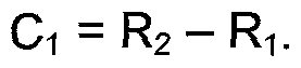
- the coils 112 have an external radius R 2 .
- R 2 the radius of the smallest circle that encompasses all the coils.
- R 1 the radius of the largest circle that fits within the confines of all the coils.
- the coils are sensibly arranged in a circle around the rotor axis 120, but that is not absolutely required.
- the coils have radial (C 1 ) and circumferential (C 2 ) extents, where
- the circumferential extent can be anything, it is defined as the centre-to-centre arc, centred on the rotor axis 120, between adjacent coils.
- k 2 is between 0.5 and 0.8, and k 3 is between 0.75 and 2.0.
- k 3 is between 0.75 and 2.0.
- bearings 164a,b are shown as ball bearings having their own races, the design permits bearing surfaces to be formed on respective frusto-conical or cylindrical surfaces of the inner stator housing 146 and cylindrical flanges 166, and for taper roller bearings, confined to a cage, to be disposed between them. This can result in even tighter tolerances being achieved.
- the rotor components are constructed from a ferromagnetic material such as steel and may be cast or forged and machined as required.
- the inner stator housing 146, and indeed the motor housing 102 is conveniently cast from non-magnetic material such as aluminium (alloy). Even aluminium can have a hardened bearing surface however.
- the present design enables an air gap in the order of 1.0mm ( ⁇ 0.1 mm) to be maintained at minimum manufacturing cost.
- the two motors 100a, b are independent.
- the rotors 114 are not connected to each other. However, they clearly could be, by disposing an appropriate spacer between them, and extending the bolts 170 so that they pass through both rotors. Indeed, there is nothing to prevent further motors being added in series, so that three or more motors could be employed in tandem.
- the sides of the composite motor are closed by covers 178 that are a press fit inside internally-cylindrical extensions
- the covers are dished pressings and are a press fit inside the extensions 102c,d although other methods of fixing are conceivable. They have a central opening through which a motor out put 190 extends.
- the output 190 comprises any suitable component and may be a shaft.
- it is shown as a standard drive hub having a tripod-cup 192 for reception of a shaft (not shown) having a three-lobed yoke.
- a seal (not shown) would normally be disposed between the cover 178 and the hub 190 to isolate the internal environment of the motor 100.
- the hub 190 is connected by an annular disc 194 to the rotor 114.
- the disc 194 is secured to the rotor by the bolts and nuts 170, and to the hub 190 by bolts (not shown) in apertures 196 in the hub 190.
- the shaft-less topology allows for a wide variety of output configurations, including:
- the motor is arranged to drive two vehicle wheels.
- a further motor could be arranged to drive other pairs of wheels in multi-axle vehicles.
- the motor would be arranged substantially centrally between the wheels with drive shafts extending from each of the two drive hubs
- the covers 178 are merely dust excluders and protect the internal components of the machine 100. They have little if any structural role.
- the structural connections between a fixture (such as a vehicle in which the machine is disposed) and the output are as follows.
- the fixture is connected to the motor housing.
- the motor housing structurally mounts the stator.
- the stator structurally, although also rotationally, mounts the rotor.
- the rotor structurally mounts the output, which is not otherwise structurally supported by the motor housing.
- the term “structurally” is being used in the sense that the mountings are the main or only mountings for the component in question.
- a housing mounts a stator and also (rotationally) mounts a rotor. It could be suggested therefore that the stator mounts the rotor.
- such mounting is incidental and is not what is meant herein by structural mounting through the substantially exclusive agency of the component in question.
- a seal disposed between the cover 178 and the hub 190 neither "mounts" the hub on the cover, let alone structurally, and does not disturb the fundamental structural mounting of the hub in the housing through the agency of the rotor and stator.
- a gear box is not necessary because the electronics required to manage the coils can enable the machine to operate at a substantially constant maximum torque (subject substantially only to cooling limitations) over a wide range of speeds, for example torques of 500Nm per motor slice, to rotational speeds in excess of 3000rpm, are feasible. Nevertheless, this option is distinctly available.
- the four slice motor (not shown) can be made simply by continuing the addition of rotors114 leftwardly in Figure 8.
- a dual-drive four-slice motor can be achieved simply by mirroring the arrangement in the bottom half of Figure 8, removing the continuous covers 178' and connecting the annular housings 102 of each pair together.
- a slice does not necessarily have to be a further motor slice 100a,b - it could be a separate gearbox slice to provide an alternative torque-speed balance. So, in example (a) above, the slice could be added to an epicyclic gearbox that steps the rotational speed down by, for example, a factor of 4:1. This would reduce the maximum output speed but will conversely give 2000Nm torque (500Nm x 4) from a very light weight assembly.
- these figures apply to the topology illustrated in Figures 7 to 13 employing 18 stator poles and 20 magnets per rotor. However, other options are of course available, in either direction, down to 300Nm and upwards of 1000Nm.
Landscapes
- Engineering & Computer Science (AREA)
- Power Engineering (AREA)
- Manufacturing & Machinery (AREA)
- Motor Or Generator Cooling System (AREA)
- Iron Core Of Rotating Electric Machines (AREA)
- Permanent Magnet Type Synchronous Machine (AREA)
- Permanent Field Magnets Of Synchronous Machinery (AREA)
- Motor Or Generator Frames (AREA)
Abstract
Description
Claims
Priority Applications (6)
| Application Number | Priority Date | Filing Date | Title |
|---|---|---|---|
| JP2011549676A JP5778041B2 (en) | 2009-02-13 | 2010-02-12 | Electromechanical-cooling |
| US13/148,871 US9496776B2 (en) | 2009-02-13 | 2010-02-12 | Cooled electric machine |
| EP10705174.0A EP2396871B1 (en) | 2009-02-13 | 2010-02-12 | Electric machine - cooling |
| KR1020117021086A KR101747975B1 (en) | 2009-02-13 | 2010-02-12 | Electric machine - cooling |
| BRPI1008424 BRPI1008424B1 (en) | 2009-02-13 | 2010-02-12 | electric machine and electric cooling machine construction method |
| CN201080016547.0A CN102396134B (en) | 2009-02-13 | 2010-02-12 | Motor-cooling |
Applications Claiming Priority (2)
| Application Number | Priority Date | Filing Date | Title |
|---|---|---|---|
| GBGB0902394.6A GB0902394D0 (en) | 2009-02-13 | 2009-02-13 | Electric machine- cooling |
| GB0902394.6 | 2009-02-13 |
Publications (2)
| Publication Number | Publication Date |
|---|---|
| WO2010092400A2 true WO2010092400A2 (en) | 2010-08-19 |
| WO2010092400A3 WO2010092400A3 (en) | 2011-06-23 |
Family
ID=40548128
Family Applications (1)
| Application Number | Title | Priority Date | Filing Date |
|---|---|---|---|
| PCT/GB2010/050234 Ceased WO2010092400A2 (en) | 2009-02-13 | 2010-02-12 | Electric machine - cooling |
Country Status (8)
| Country | Link |
|---|---|
| US (1) | US9496776B2 (en) |
| EP (1) | EP2396871B1 (en) |
| JP (1) | JP5778041B2 (en) |
| KR (1) | KR101747975B1 (en) |
| CN (1) | CN102396134B (en) |
| BR (1) | BRPI1008424B1 (en) |
| GB (2) | GB0902394D0 (en) |
| WO (1) | WO2010092400A2 (en) |
Cited By (25)
| Publication number | Priority date | Publication date | Assignee | Title |
|---|---|---|---|---|
| WO2012022974A1 (en) | 2010-08-19 | 2012-02-23 | Oxford Yasa Motors Limited | Electric machine - over-moulding construction |
| WO2012156719A3 (en) * | 2011-05-18 | 2013-02-28 | Ashwoods Automotive Limited | Axial flux electrical machines |
| US20130187492A1 (en) * | 2010-10-08 | 2013-07-25 | Oxford Yasa Motors Limited | Wheel-hub motor cooling |
| US8581455B2 (en) | 2009-04-14 | 2013-11-12 | Isis Innovation Ltd. | Electric machine—evaporative cooling |
| WO2014080183A1 (en) * | 2012-11-20 | 2014-05-30 | Ashwoods Automotive Limited | Axial air gap electrical machine |
| EP2835895A3 (en) * | 2013-08-08 | 2015-05-27 | Yasa Motors Ltd | Cooling of axial flux motors - centrifugal |
| US9071117B2 (en) | 2009-02-13 | 2015-06-30 | Isis Innovation Ltd. | Electric machine—flux |
| US9318938B2 (en) | 2009-02-13 | 2016-04-19 | Isis Innovation Ltd. | Electric machine-modular |
| WO2018015293A1 (en) | 2016-07-18 | 2018-01-25 | Universiteit Gent | Stator for an axial flux machine and method for producing the same |
| RU2666777C2 (en) * | 2013-09-13 | 2018-09-12 | Яса Лимитед | Injection molding onto the stator plate |
| EP2909116B1 (en) * | 2012-10-18 | 2019-02-13 | Laitram, LLC | Belt conveyor and electromagnetic drive |
| EP3764526A1 (en) | 2019-07-10 | 2021-01-13 | Magnax Bv | Cooling mechanism of a stator for an axial flux machine |
| WO2021032236A1 (en) * | 2019-08-20 | 2021-02-25 | Schaeffler Technologies AG & Co. KG | Disc rotor machine for a motor vehicle drive |
| US10985089B2 (en) | 2017-01-30 | 2021-04-20 | Yasa Limited | Semiconductor cooling arrangement |
| WO2021123900A1 (en) * | 2019-12-20 | 2021-06-24 | Ka Group Ag | Drive assembly with integrated cooling |
| WO2021180267A1 (en) * | 2020-03-12 | 2021-09-16 | Schaeffler Technologies AG & Co. KG | Stator for an axial flux machine, method for producing a stator and axial flux machine |
| US11276622B2 (en) | 2017-01-30 | 2022-03-15 | Yasa Limited | Inverter arrangement |
| DE102022210663A1 (en) | 2022-10-10 | 2023-11-02 | Vitesco Technologies GmbH | Busbar system for supplying a stator of an axial flux machine and stator |
| DE102022210419A1 (en) | 2022-09-30 | 2024-04-04 | Vitesco Technologies GmbH | Stator housing and stator for an axial flux machine |
| EP4443711A1 (en) | 2023-04-06 | 2024-10-09 | Magnax | Core sleeve arrangement for an axial flux machine |
| EP4535614A1 (en) | 2023-10-02 | 2025-04-09 | Magnax | Axial flux machine with direct core cooling |
| EP4568075A1 (en) | 2023-12-05 | 2025-06-11 | Schaeffler Technologies AG & Co. KG | Connection structure for a yokeless and segmented armature axial flux machine |
| EP4568069A1 (en) | 2023-12-05 | 2025-06-11 | Schaeffler Technologies AG & Co. KG | Rotor connection to shaft for axial flux motor |
| EP4535619A3 (en) * | 2019-01-14 | 2025-07-23 | Shanghai Pangood Power Technology Co., Ltd. | Axial magnetic field motor with liquid cooled stator |
| EP4672559A1 (en) | 2024-06-24 | 2025-12-31 | Magnax | COIL CLAMPING SOLUTION FOR AN AXIAL FLUID MACHINE |
Families Citing this family (76)
| Publication number | Priority date | Publication date | Assignee | Title |
|---|---|---|---|---|
| TWI509954B (en) * | 2011-01-26 | 2015-11-21 | Asia Vital Components Co Ltd | Motor water cooling structure and manufacturing method thereof |
| CN102801264B (en) * | 2012-09-04 | 2015-02-11 | 魏乐汉 | Permanent magnet laminated motor |
| WO2014085479A1 (en) * | 2012-11-30 | 2014-06-05 | Applied Materials, Inc | Multi-axis robot apparatus with unequal length forearms, electronic device manufacturing systems, and methods for transporting substrates in electronic device manufacturing |
| KR20140084494A (en) * | 2012-12-26 | 2014-07-07 | 현대모비스 주식회사 | Cooling Apparatus for Axial Flux Permanent Magnet Motor |
| GB201301758D0 (en) | 2013-01-31 | 2013-03-20 | Yasa Motors Ltd | Shoe cooling cap |
| KR101999860B1 (en) * | 2013-03-28 | 2019-07-12 | 현대모비스 주식회사 | Housing assembly and axial flux permanent magnet motor |
| KR101440431B1 (en) * | 2013-03-28 | 2014-09-17 | 현대모비스(주) | axial flux permanent magnet motor |
| GB2518209B (en) | 2013-09-13 | 2016-08-03 | Yasa Motors Ltd | Pole-piece Bonding |
| US9667106B2 (en) * | 2013-09-25 | 2017-05-30 | Regal Beloit Australia Pty Ltd | Motor housing and methods of assembling the same |
| GB2525157B (en) * | 2014-02-18 | 2016-08-24 | Yasa Motors Ltd | Machine cooling systems |
| JP2015226334A (en) * | 2014-05-26 | 2015-12-14 | 株式会社神戸製鋼所 | Electric motor |
| JP6270213B2 (en) * | 2014-06-05 | 2018-01-31 | 株式会社神戸製鋼所 | Electric motor |
| CN104113171A (en) * | 2014-06-24 | 2014-10-22 | 华中科技大学 | Yoke-free closed slot type multi-plate permanent magnet motor |
| GB2534195B (en) | 2015-01-16 | 2018-02-21 | Yasa Ltd | Axial flux machine manufacture |
| GB2538526B (en) * | 2015-05-19 | 2021-05-26 | Yasa Ltd | Axial flux machine |
| CN104901455A (en) * | 2015-05-26 | 2015-09-09 | 芜湖品通塑业科技有限公司 | Rotor for motor of bag making machine |
| US11139707B2 (en) | 2015-08-11 | 2021-10-05 | Genesis Robotics And Motion Technologies Canada, Ulc | Axial gap electric machine with permanent magnets arranged between posts |
| RU2018108629A (en) | 2015-08-11 | 2019-09-12 | Дженезис Роботикс Энд Мотион Текнолоджиз Канада, Улс | ELECTRIC MACHINE |
| JP2017060281A (en) * | 2015-09-16 | 2017-03-23 | マツダ株式会社 | Stator, axial gap type rotating electrical machine, and stator manufacturing method |
| JP6365516B2 (en) * | 2015-11-26 | 2018-08-01 | マツダ株式会社 | Stator and axial gap type rotating electric machine including the stator |
| GB2546256A (en) * | 2016-01-07 | 2017-07-19 | Mclaren Applied Tech Ltd | Electrical machine |
| CN105553126A (en) * | 2016-01-13 | 2016-05-04 | 西安交通大学 | Stator cooling structure of built-in disc type motor |
| CN105553204B (en) * | 2016-02-24 | 2019-02-19 | 深圳小象电动科技有限公司 | Water-cooled machine |
| CN105576927B (en) * | 2016-03-09 | 2019-01-15 | 深圳小象电动科技有限公司 | The disc-type electric motor that stator immersion oil radiates and rotor is built-in |
| CN105896766A (en) * | 2016-04-19 | 2016-08-24 | 北京康城科技有限公司 | Stator liquid cooling structure for built-in disc type motor |
| JP6402739B2 (en) * | 2016-04-19 | 2018-10-10 | マツダ株式会社 | Rotating electric machine |
| US11043885B2 (en) | 2016-07-15 | 2021-06-22 | Genesis Robotics And Motion Technologies Canada, Ulc | Rotary actuator |
| CN106324085A (en) * | 2016-08-30 | 2017-01-11 | 中国海洋石油总公司 | Pulse eddy current testing probe |
| US10608509B2 (en) * | 2016-10-17 | 2020-03-31 | Roul Delroy MARTIN | Rotatable electric machines |
| CN106452013B (en) * | 2016-11-23 | 2019-02-01 | 中国科学院电工研究所 | A kind of winding strengthens the axial magnetic flux hub motor of heat dissipation |
| CN108233557A (en) * | 2016-12-15 | 2018-06-29 | 姚常勤 | A kind of motor stator module and the Stator and electrical machine with the module |
| US10630127B1 (en) | 2017-01-06 | 2020-04-21 | Apple Inc. | Electric motor with bar wound stator and end turn cooling |
| GB2558677A (en) * | 2017-02-06 | 2018-07-18 | Libertine Fpe Ltd | Linear electrical machine |
| FR3076674B1 (en) * | 2018-01-09 | 2022-03-04 | Whylot Sas | ELECTROMAGNETIC MOTOR OR GENERATOR WITH TWO ROTORS AND FOUR STATORS AND INTEGRATED COOLING SYSTEM |
| CN108574350B (en) * | 2018-05-29 | 2021-04-02 | 南方电机科技有限公司 | Stator of axial flux motor, axial flux motor and automation equipment |
| CN111120583B (en) * | 2018-10-31 | 2023-06-30 | 日本电产株式会社 | Speed reducer and electromechanical device |
| CN209150811U (en) | 2018-12-10 | 2019-07-23 | 日本电产株式会社 | Stator elements, stator assemblies, motors and electromechanical devices |
| CN109450174B (en) * | 2019-01-14 | 2024-09-06 | 上海盘毂动力科技股份有限公司 | A cooling system and a motor |
| CN109474114B (en) * | 2019-01-14 | 2024-11-12 | 上海盘毂动力科技股份有限公司 | Axial magnetic field motor |
| CN109462311B (en) * | 2019-01-14 | 2025-04-04 | 上海盘毂动力科技股份有限公司 | A cooling system and a motor |
| CN111725907B (en) * | 2019-03-19 | 2026-02-17 | 上海盘毂动力科技股份有限公司 | Stator assembly and axial magnetic field motor |
| AU2020236533A1 (en) * | 2019-03-08 | 2021-11-11 | FluxSystems Pty Ltd | Method and apparatus for motor cooling |
| CN111725910B (en) * | 2019-03-19 | 2025-09-09 | 上海盘毂动力科技股份有限公司 | Stator assembly and axial magnetic field motor |
| WO2020212787A1 (en) * | 2019-04-15 | 2020-10-22 | Vishal Sharma | Dual airgap electrical machines |
| DE102019125871A1 (en) * | 2019-09-25 | 2021-03-25 | Schaeffler Technologies AG & Co. KG | Axial flow machine |
| IT201900018461A1 (en) * | 2019-10-10 | 2021-04-10 | Texa Dynamics S R L | "Cooling component for electric motor" |
| US11936256B2 (en) | 2020-04-24 | 2024-03-19 | Jacobi Motors, Llc | Flux-mnemonic permanent magnet synchronous machine and magnetizing a flux-mnemonic permanent magnet synchronous machine |
| CN113922526B (en) * | 2020-07-08 | 2025-06-27 | 湖州硬核派科技有限公司 | Axial flux motor stator and motor thereof |
| US11199192B1 (en) * | 2020-07-30 | 2021-12-14 | Hewlett Packard Enterprise Development Lp | Pump assembly having performance enhancing hose connection ports |
| US12040690B2 (en) * | 2020-08-31 | 2024-07-16 | General Electric Company | Cooling a stator housing of an electric machine |
| DE102021127747A1 (en) * | 2020-10-26 | 2022-04-28 | Schaeffler Technologies AG & Co. KG | Electrical machine assembly |
| DE102020132490B4 (en) | 2020-12-07 | 2022-12-01 | Schaeffler Technologies AG & Co. KG | Electrical axial flow machine and axle with electrical drive |
| WO2022160027A1 (en) * | 2021-02-01 | 2022-08-04 | Weg Equipamentos Eletricos S.A. | Axial-flux electric machine and method for assembling a stator of an axial-flux electric machine |
| GB202105829D0 (en) | 2021-04-23 | 2021-06-09 | Yasa Ltd | Rotor |
| KR102348964B1 (en) * | 2021-05-18 | 2022-01-12 | 주식회사 이플로우 | Axial flux motor |
| US20240291369A1 (en) * | 2021-06-22 | 2024-08-29 | Tejo Energia Industria Comercio E Servicos Ltda | Vertical Propulsion Magnetic Generation Turbine |
| KR20240043949A (en) * | 2022-09-28 | 2024-04-04 | 현대자동차주식회사 | Stator for AFPM motor and manufacturing method thereof |
| FR3144447A1 (en) * | 2022-12-22 | 2024-06-28 | Valeo Equipements Electriques Moteur | Axial flow rotating electric machine |
| GB2626145A (en) | 2023-01-11 | 2024-07-17 | Rolls Royce Deutschland Ltd & Co Kg | Electrical machines for aircraft power and propulsion systems |
| US11827371B1 (en) | 2023-01-11 | 2023-11-28 | Rolls-Royce Deutschland Ltd & Co Kg | Electrical machines for aircraft power and propulsion systems |
| GB2627179A (en) | 2023-01-11 | 2024-08-21 | Rolls Royce Deutschland Ltd & Co Kg | Electrical machines for aircraft power and propulsion systems |
| US11824410B1 (en) | 2023-01-11 | 2023-11-21 | Rolls-Royce Deutschland Ltd & Co Kg | Electrical machines for aircraft power and propulsion systems |
| US11990805B1 (en) | 2023-01-11 | 2024-05-21 | Rolls-Royce Deutschland Ltd & Co Kg | Electrical machines for aircraft power and propulsion systems having a defined machine parameter based on a ratio between an active parts torque density and a power factor |
| GB2627184B (en) | 2023-02-03 | 2025-09-10 | Evolito Ltd | Axial flux machine rotor |
| GB2626960B (en) | 2023-02-08 | 2025-09-24 | Evolito Ltd | A Stator |
| PE20260237A1 (en) * | 2023-02-16 | 2026-01-28 | Inst Hercilio Randon | AXIAL FLUID ELECTRIC MACHINE AND ELECTRIC MACHINE MANUFACTURING PROCESS |
| GB2629139B (en) * | 2023-04-14 | 2025-07-16 | Evolito Ltd | Containment Ring |
| WO2025072428A1 (en) * | 2023-09-28 | 2025-04-03 | Infinitum Electric, Inc. | Printed circuit board stator axial field rotary energy device with ferromagnetic core |
| US12558980B2 (en) | 2023-11-09 | 2026-02-24 | Jacobi Motors, Llc | Integrated variable flux memory motor charger |
| US12614998B2 (en) | 2024-03-04 | 2026-04-28 | Jacobi Motors, Llc | System for multi-variable flux memory motor configuration |
| WO2025254728A1 (en) | 2024-06-06 | 2025-12-11 | Skip Innovations, Inc. | Exosuit with axial flux electromagnetic motors |
| GB2643525A (en) | 2024-08-19 | 2026-02-25 | Evolito Ltd | Axial flux machine rotor |
| DE102024002964A1 (en) | 2024-09-13 | 2026-03-19 | Mercedes-Benz Group AG | Axial flux machine for a motor vehicle and methods for operating such an axial flux machine |
| DE102024002965A1 (en) | 2024-09-13 | 2026-03-19 | Mercedes-Benz Group AG | Axial flux machine for a motor vehicle and methods for operating such an axial flux machine |
| DE102024003603A1 (en) | 2024-10-31 | 2026-04-30 | Mercedes-Benz Group AG | Stator for an axial flux machine, in particular for a motor vehicle, as well as axial flux machine |
| DE102024003602A1 (en) | 2024-10-31 | 2026-04-30 | Mercedes-Benz Group AG | Stator for an axial flux machine, in particular for a motor vehicle, as well as axial flux machine |
Citations (6)
| Publication number | Priority date | Publication date | Assignee | Title |
|---|---|---|---|---|
| GB2379093A (en) | 2001-08-22 | 2003-02-26 | Chia-Hao Fan | Side rotation (axial) type motor/dynamo |
| WO2003094327A1 (en) | 2002-04-30 | 2003-11-13 | Wavecrest Laboratories Llc | Rotary electric motor having at least two axially air gaps separating stator and rotor segments |
| US6720688B1 (en) | 1999-02-12 | 2004-04-13 | Helmut Schiller | Electric machine |
| US20050035676A1 (en) | 2003-08-11 | 2005-02-17 | Rahman Khwaja M. | Gearless wheel motor drive system |
| WO2006066740A1 (en) | 2004-12-15 | 2006-06-29 | Helmut Schiller | Electric motor |
| US20070046124A1 (en) | 2005-09-01 | 2007-03-01 | Metin Aydin | Field controlled axial flux permanent magnet electrical machine |
Family Cites Families (79)
| Publication number | Priority date | Publication date | Assignee | Title |
|---|---|---|---|---|
| US2606946A (en) | 1950-07-19 | 1952-08-12 | Gen Electric | Dynamoelectric machine cooling and brush lubrication |
| US3150277A (en) | 1962-03-14 | 1964-09-22 | Worthington Corp | Hermetic motor cooling by liquid refrigerant |
| US3217193A (en) | 1963-03-08 | 1965-11-09 | Worthington Corp | Liquid cooled motor arrangement |
| US3413503A (en) | 1966-01-13 | 1968-11-26 | Louis W. Parker | Axial airgap motors |
| SU551763A1 (en) | 1972-08-03 | 1977-03-25 | ||
| JPS5088510A (en) | 1973-12-10 | 1975-07-16 | ||
| DE2705623A1 (en) | 1977-02-10 | 1978-08-17 | Nihon Radiator Co | ENGINE WITH PRINTED WRAP |
| US4435662A (en) * | 1979-05-11 | 1984-03-06 | Gen-Tech, Inc. | Axial air gap alternators/generators of modular construction |
| SU955379A1 (en) | 1981-01-19 | 1982-08-30 | Могилевский Машиностроительный Институт | Electric machine |
| US4447750A (en) | 1982-06-23 | 1984-05-08 | International Scientific Industries, Inc. | Electromagnetic device construction |
| US4464592A (en) * | 1982-07-14 | 1984-08-07 | Emery Major | Prime mover |
| JPS62201034A (en) | 1986-02-27 | 1987-09-04 | Shin Meiwa Ind Co Ltd | Direct drive motor |
| JPS63209455A (en) | 1987-02-23 | 1988-08-31 | Olympus Optical Co Ltd | Motor |
| US5578879A (en) * | 1989-09-28 | 1996-11-26 | Heidelberg; G+E,Uml O+Ee Tz | Electric machine with fluid cooling |
| HK1006958A1 (en) | 1990-05-24 | 1999-03-26 | 精工爱普生株式会社 | Electric automobile |
| JPH04359653A (en) | 1991-02-27 | 1992-12-11 | Shin Meiwa Ind Co Ltd | Cooling equipment for motor |
| JPH0591696A (en) * | 1991-09-26 | 1993-04-09 | Mitsubishi Electric Corp | Rotating machine |
| US5334899A (en) | 1991-09-30 | 1994-08-02 | Dymytro Skybyk | Polyphase brushless DC and AC synchronous machines |
| JPH05185847A (en) | 1992-01-13 | 1993-07-27 | Max:Kk | Driving wheel structure for electric automobile |
| US5327034A (en) | 1992-07-14 | 1994-07-05 | Hydro-Quebec | Electrically motorized wheel assembly |
| US5517072A (en) | 1992-12-24 | 1996-05-14 | Efficient Propulsion, Inc. | Method and apparatus for increasing the efficiency of electrical rotary machines |
| US5394040A (en) | 1993-09-07 | 1995-02-28 | Heat Pipe Technology, Inc. | Electric motor having internal heat dissipator |
| DE19600612A1 (en) | 1996-01-10 | 1997-07-17 | Elektrische Automatisierungs U | Loss heat removal for rotors with magnetic bearings |
| EP0917757B1 (en) * | 1996-08-09 | 2004-10-13 | The Turbo Genset Company Limited | Rotary electrical machines |
| US5894902A (en) | 1996-09-05 | 1999-04-20 | The United States Of America As Represented By The Secretary Of The Navy | Self-propelled wheel for wheeled vehicles |
| US5982070A (en) * | 1996-12-27 | 1999-11-09 | Light Engineering Corporation | Electric motor or generator having amorphous core pieces being individually accomodated in a dielectric housing |
| US5910697A (en) * | 1997-01-17 | 1999-06-08 | Samon Engineering Ltd. | High-power, low-voltage axial air-gap electrical machine having a compact stator |
| JP2002504040A (en) | 1997-06-06 | 2002-02-05 | ミヒャエル、クッター | Hybrid propulsion system for man-powered vehicles with auxiliary electric motor |
| JP3944799B2 (en) | 1997-12-12 | 2007-07-18 | 株式会社安川電機 | Linear motor |
| US6100615A (en) | 1998-05-11 | 2000-08-08 | Birkestrand; Orville J. | Modular motorized electric wheel hub assembly for bicycles and the like |
| FR2795458B1 (en) * | 1999-06-24 | 2002-06-14 | Jeumont Ind | MOTOR FAN FOR CIRCULATING A FLUID IN A HEAT EXCHANGE INSTALLATION AND METHOD FOR COOLING THE MOTOR DRIVE OF THE MOTOR FAN |
| JP3661529B2 (en) * | 1999-11-17 | 2005-06-15 | 日産自動車株式会社 | Motor cooling device |
| US20040174087A1 (en) | 2000-05-06 | 2004-09-09 | Markus Heidrich | Stator |
| JP2002281722A (en) | 2001-03-22 | 2002-09-27 | Matsushita Electric Ind Co Ltd | Outer rotor motor and electric vehicle |
| FR2823382B1 (en) * | 2001-04-04 | 2003-08-22 | Renault Sas | ELECTRIC MOTOR COMPRISING AN IMPROVED COOLING SYSTEM |
| AU2002253352A1 (en) | 2001-05-02 | 2002-11-11 | Newage International Limited | A toroidal electrical machine and an annular winding carrier therefor |
| JP3702825B2 (en) | 2001-09-07 | 2005-10-05 | 日産自動車株式会社 | Stator support structure for rotating electrical machines |
| CN1258254C (en) * | 2002-04-01 | 2006-05-31 | 日产自动车株式会社 | Stator cooling structure for multi-axis and multi-layer motors |
| US6922004B2 (en) | 2002-04-05 | 2005-07-26 | The Timken Company | Axial flux motor assembly |
| US20060103263A1 (en) | 2002-08-16 | 2006-05-18 | Shinya Naito | Rotating electric machine |
| JP4305649B2 (en) | 2003-02-26 | 2009-07-29 | 株式会社富士通ゼネラル | Axial gap type electric motor |
| JP2004274838A (en) | 2003-03-06 | 2004-09-30 | Matsushita Electric Ind Co Ltd | Wheel drive |
| JP2004312984A (en) | 2003-03-27 | 2004-11-04 | Fujitsu General Ltd | Axial gap type motor |
| DE10319190A1 (en) | 2003-04-29 | 2004-11-18 | Robert Bosch Gmbh | Electrical machine |
| EP1649574A2 (en) | 2003-07-10 | 2006-04-26 | Magnetic Applications Inc. | Compact high power alternator |
| CN1929260A (en) | 2003-07-29 | 2007-03-14 | 发那科株式会社 | Motor and motor manufacturing apparatus |
| JP4060252B2 (en) | 2003-08-25 | 2008-03-12 | 山洋電気株式会社 | Fan motor |
| JP2005151725A (en) | 2003-11-17 | 2005-06-09 | Equos Research Co Ltd | Axial gap rotating electric machine |
| JP2005171835A (en) | 2003-12-10 | 2005-06-30 | Fujitsu General Ltd | Blower |
| JP2005185075A (en) | 2003-12-24 | 2005-07-07 | Fujitsu General Ltd | Axial gap type electric motor |
| JP3936340B2 (en) * | 2004-02-04 | 2007-06-27 | 国立大学法人福井大学 | Superconducting synchronous machine |
| JP2005224054A (en) | 2004-02-06 | 2005-08-18 | Fujitsu General Ltd | Axial gap type electric motor |
| JP4470037B2 (en) | 2004-03-03 | 2010-06-02 | 株式会社エクォス・リサーチ | Axial gap rotating electric machine |
| JP4082359B2 (en) | 2004-03-11 | 2008-04-30 | 日産自動車株式会社 | Cooling structure of rotating electric machine |
| JP2006014522A (en) | 2004-06-28 | 2006-01-12 | Nissan Motor Co Ltd | Motor cooling structure |
| JP2006033965A (en) * | 2004-07-14 | 2006-02-02 | Nissan Motor Co Ltd | Stator cooling structure of disk-type dynamo-electric machine |
| US7411325B1 (en) | 2004-10-20 | 2008-08-12 | Revolution Electric Motor Company, Inc. | High efficiency combination motor and drive |
| JP4687871B2 (en) | 2004-11-26 | 2011-05-25 | 株式会社富士通ゼネラル | Axial gap type electric motor |
| US7622012B2 (en) | 2005-02-09 | 2009-11-24 | Mitsubishi Materials Corporation | Flat soft magnetic metal powder and composite magnetic material including the soft magnetic metal powder |
| JP4550631B2 (en) | 2005-03-11 | 2010-09-22 | 本田技研工業株式会社 | Wheel drive device for vehicle |
| JP4720982B2 (en) | 2005-04-20 | 2011-07-13 | 株式会社富士通ゼネラル | Axial air gap type electric motor |
| JP4706339B2 (en) | 2005-06-03 | 2011-06-22 | 株式会社富士通ゼネラル | Axial air gap type electric motor |
| JP2007014147A (en) | 2005-06-30 | 2007-01-18 | Fujitsu General Ltd | Electric motor |
| JP4904736B2 (en) * | 2005-07-21 | 2012-03-28 | 日産自動車株式会社 | Rotating electric machine stator |
| JP2007060748A (en) | 2005-08-22 | 2007-03-08 | Sumitomo Electric Ind Ltd | Superconducting multi-axis motor and vehicle equipped with the same |
| JP2007143365A (en) | 2005-11-22 | 2007-06-07 | Keun Yang Industrial Co Ltd | AC motor stator structure |
| JP2007215311A (en) | 2006-02-09 | 2007-08-23 | Nissan Motor Co Ltd | In-wheel motor cooling device, cooling method, and vehicle with cooling device |
| TWI433433B (en) | 2006-03-10 | 2014-04-01 | Hitachi Metals Ltd | Bonded magnet and magnetic roller |
| GB0610933D0 (en) | 2006-06-02 | 2006-07-12 | Nexxtdrive Ltd | Electric machine |
| US7445067B2 (en) | 2006-08-31 | 2008-11-04 | American Axle & Manufacturing, Inc. | Electric wheel motor assembly |
| WO2008032430A1 (en) | 2006-09-13 | 2008-03-20 | Ntn Corporation | Motor-integrated magnetic bearing device |
| JP2008079397A (en) | 2006-09-20 | 2008-04-03 | Nissan Motor Co Ltd | Variable air gap type rotating electrical machine |
| US20080099258A1 (en) | 2006-10-26 | 2008-05-01 | Berhan Michael T | Vented sealed housing assembly for vehicle powertrain |
| US8558425B2 (en) * | 2006-10-26 | 2013-10-15 | Deere & Company | Motor having stator with generally planar windings |
| JP2008131684A (en) | 2006-11-16 | 2008-06-05 | Fujitsu General Ltd | Electric motor drive system |
| KR100870738B1 (en) | 2007-01-25 | 2008-11-26 | 태창엔이티 주식회사 | FPM Coreless Multi-Generator & Motor |
| FR2911917B1 (en) | 2007-01-31 | 2013-05-17 | Hispano Suiza Sa | DISTRIBUTED GAS TURBINE GENERATOR-STARTER ARCHITECTURE |
| GB0906284D0 (en) | 2009-04-14 | 2009-05-20 | Isis Innovation | Electric machine-evaporative cooling |
| JP5502463B2 (en) | 2009-12-28 | 2014-05-28 | 株式会社日立産機システム | Axial gap type rotating electric machine and rotor used therefor |
-
2009
- 2009-02-13 GB GBGB0902394.6A patent/GB0902394D0/en not_active Ceased
-
2010
- 2010-02-12 JP JP2011549676A patent/JP5778041B2/en active Active
- 2010-02-12 EP EP10705174.0A patent/EP2396871B1/en active Active
- 2010-02-12 GB GB1002406.5A patent/GB2468018B/en active Active
- 2010-02-12 BR BRPI1008424 patent/BRPI1008424B1/en active IP Right Grant
- 2010-02-12 WO PCT/GB2010/050234 patent/WO2010092400A2/en not_active Ceased
- 2010-02-12 US US13/148,871 patent/US9496776B2/en active Active
- 2010-02-12 CN CN201080016547.0A patent/CN102396134B/en active Active
- 2010-02-12 KR KR1020117021086A patent/KR101747975B1/en active Active
Patent Citations (6)
| Publication number | Priority date | Publication date | Assignee | Title |
|---|---|---|---|---|
| US6720688B1 (en) | 1999-02-12 | 2004-04-13 | Helmut Schiller | Electric machine |
| GB2379093A (en) | 2001-08-22 | 2003-02-26 | Chia-Hao Fan | Side rotation (axial) type motor/dynamo |
| WO2003094327A1 (en) | 2002-04-30 | 2003-11-13 | Wavecrest Laboratories Llc | Rotary electric motor having at least two axially air gaps separating stator and rotor segments |
| US20050035676A1 (en) | 2003-08-11 | 2005-02-17 | Rahman Khwaja M. | Gearless wheel motor drive system |
| WO2006066740A1 (en) | 2004-12-15 | 2006-06-29 | Helmut Schiller | Electric motor |
| US20070046124A1 (en) | 2005-09-01 | 2007-03-01 | Metin Aydin | Field controlled axial flux permanent magnet electrical machine |
Cited By (39)
| Publication number | Priority date | Publication date | Assignee | Title |
|---|---|---|---|---|
| US9318938B2 (en) | 2009-02-13 | 2016-04-19 | Isis Innovation Ltd. | Electric machine-modular |
| US9071117B2 (en) | 2009-02-13 | 2015-06-30 | Isis Innovation Ltd. | Electric machine—flux |
| US9054566B2 (en) | 2009-04-14 | 2015-06-09 | Isis Innovation Ltd | Electric machine—evaporative cooling |
| US8581455B2 (en) | 2009-04-14 | 2013-11-12 | Isis Innovation Ltd. | Electric machine—evaporative cooling |
| WO2012022974A1 (en) | 2010-08-19 | 2012-02-23 | Oxford Yasa Motors Limited | Electric machine - over-moulding construction |
| US20130187492A1 (en) * | 2010-10-08 | 2013-07-25 | Oxford Yasa Motors Limited | Wheel-hub motor cooling |
| WO2012156719A3 (en) * | 2011-05-18 | 2013-02-28 | Ashwoods Automotive Limited | Axial flux electrical machines |
| EP2909116B1 (en) * | 2012-10-18 | 2019-02-13 | Laitram, LLC | Belt conveyor and electromagnetic drive |
| WO2014080183A1 (en) * | 2012-11-20 | 2014-05-30 | Ashwoods Automotive Limited | Axial air gap electrical machine |
| WO2015019107A3 (en) * | 2013-08-08 | 2015-06-11 | Yasa Motors Limited | Cooling of axial flux motors - centrifugal |
| EP2835895A3 (en) * | 2013-08-08 | 2015-05-27 | Yasa Motors Ltd | Cooling of axial flux motors - centrifugal |
| US10224786B2 (en) | 2013-08-08 | 2019-03-05 | Yasa Limited | Cooling of axial flux motors—centrifugal |
| RU2666777C2 (en) * | 2013-09-13 | 2018-09-12 | Яса Лимитед | Injection molding onto the stator plate |
| US11387710B2 (en) | 2016-07-18 | 2022-07-12 | Universiteit Gent | Stator for an axial flux machine and method for producing the same |
| WO2018015293A1 (en) | 2016-07-18 | 2018-01-25 | Universiteit Gent | Stator for an axial flux machine and method for producing the same |
| US11276622B2 (en) | 2017-01-30 | 2022-03-15 | Yasa Limited | Inverter arrangement |
| US10985089B2 (en) | 2017-01-30 | 2021-04-20 | Yasa Limited | Semiconductor cooling arrangement |
| EP4535619A3 (en) * | 2019-01-14 | 2025-07-23 | Shanghai Pangood Power Technology Co., Ltd. | Axial magnetic field motor with liquid cooled stator |
| WO2021005084A1 (en) | 2019-07-10 | 2021-01-14 | Magnax Bv | Cooling mechanism of a stator for an axial flux machine |
| US12160155B2 (en) | 2019-07-10 | 2024-12-03 | Magnax Bv | Cooling mechanism of a stator for an axial flux machine |
| CN114072994A (en) * | 2019-07-10 | 2022-02-18 | 麦格纳有限责任公司 | Cooling mechanism for stator of axial flux electric machine |
| EP3764526A1 (en) | 2019-07-10 | 2021-01-13 | Magnax Bv | Cooling mechanism of a stator for an axial flux machine |
| CN114072994B (en) * | 2019-07-10 | 2024-03-12 | 麦格纳有限责任公司 | Cooling mechanism for the stator of an axial flux motor |
| WO2021032236A1 (en) * | 2019-08-20 | 2021-02-25 | Schaeffler Technologies AG & Co. KG | Disc rotor machine for a motor vehicle drive |
| US12334786B2 (en) | 2019-08-20 | 2025-06-17 | Schaeffler Technologies AG & Co. KG | Disc rotor machine with stator having core segents, with rotor disc with cooling device |
| WO2021123900A1 (en) * | 2019-12-20 | 2021-06-24 | Ka Group Ag | Drive assembly with integrated cooling |
| WO2021180267A1 (en) * | 2020-03-12 | 2021-09-16 | Schaeffler Technologies AG & Co. KG | Stator for an axial flux machine, method for producing a stator and axial flux machine |
| DE102022210419B4 (en) * | 2022-09-30 | 2025-05-28 | Schaeffler Technologies AG & Co. KG | Stator housing and stator for an axial flux machine |
| DE102022210419A1 (en) | 2022-09-30 | 2024-04-04 | Vitesco Technologies GmbH | Stator housing and stator for an axial flux machine |
| WO2024068211A1 (en) | 2022-09-30 | 2024-04-04 | Vitesco Technologies GmbH | Stator housing and stator for an axial flux machine |
| DE102022210663A1 (en) | 2022-10-10 | 2023-11-02 | Vitesco Technologies GmbH | Busbar system for supplying a stator of an axial flux machine and stator |
| WO2024208716A1 (en) | 2023-04-06 | 2024-10-10 | Magnax | Core sleeve arrangement for an axial flux machine |
| EP4443711A1 (en) | 2023-04-06 | 2024-10-09 | Magnax | Core sleeve arrangement for an axial flux machine |
| EP4535614A1 (en) | 2023-10-02 | 2025-04-09 | Magnax | Axial flux machine with direct core cooling |
| WO2025073465A1 (en) | 2023-10-02 | 2025-04-10 | Magnax | Axial flux machine with direct core cooling |
| EP4568075A1 (en) | 2023-12-05 | 2025-06-11 | Schaeffler Technologies AG & Co. KG | Connection structure for a yokeless and segmented armature axial flux machine |
| EP4568069A1 (en) | 2023-12-05 | 2025-06-11 | Schaeffler Technologies AG & Co. KG | Rotor connection to shaft for axial flux motor |
| EP4672559A1 (en) | 2024-06-24 | 2025-12-31 | Magnax | COIL CLAMPING SOLUTION FOR AN AXIAL FLUID MACHINE |
| WO2026002872A1 (en) | 2024-06-24 | 2026-01-02 | Magnax | Coil clamping solution for an axial flux machine |
Also Published As
| Publication number | Publication date |
|---|---|
| WO2010092400A3 (en) | 2011-06-23 |
| BRPI1008424A2 (en) | 2016-03-01 |
| CN102396134B (en) | 2016-04-20 |
| GB2468018B (en) | 2014-06-04 |
| KR20110127198A (en) | 2011-11-24 |
| EP2396871B1 (en) | 2017-06-14 |
| CN102396134A (en) | 2012-03-28 |
| GB2468018A (en) | 2010-08-25 |
| JP5778041B2 (en) | 2015-09-16 |
| GB201002406D0 (en) | 2010-03-31 |
| KR101747975B1 (en) | 2017-06-27 |
| US9496776B2 (en) | 2016-11-15 |
| GB0902394D0 (en) | 2009-04-01 |
| US20110309699A1 (en) | 2011-12-22 |
| JP2012518376A (en) | 2012-08-09 |
| EP2396871A2 (en) | 2011-12-21 |
| BRPI1008424B1 (en) | 2019-12-03 |
Similar Documents
| Publication | Publication Date | Title |
|---|---|---|
| US9496776B2 (en) | Cooled electric machine | |
| EP2396873B1 (en) | Electric machine- modular | |
| US9071117B2 (en) | Electric machine—flux | |
| US9287755B2 (en) | Electric machine—over-moulding construction | |
| US7355311B2 (en) | Rotor of axial gap motor and method of producing same |
Legal Events
| Date | Code | Title | Description |
|---|---|---|---|
| WWE | Wipo information: entry into national phase |
Ref document number: 201080016547.0 Country of ref document: CN |
|
| WWE | Wipo information: entry into national phase |
Ref document number: 13148871 Country of ref document: US Ref document number: 3374/KOLNP/2011 Country of ref document: IN |
|
| NENP | Non-entry into the national phase |
Ref country code: DE |
|
| WWE | Wipo information: entry into national phase |
Ref document number: 2011549676 Country of ref document: JP |
|
| ENP | Entry into the national phase |
Ref document number: 20117021086 Country of ref document: KR Kind code of ref document: A |
|
| REEP | Request for entry into the european phase |
Ref document number: 2010705174 Country of ref document: EP |
|
| WWE | Wipo information: entry into national phase |
Ref document number: 2010705174 Country of ref document: EP |
|
| 121 | Ep: the epo has been informed by wipo that ep was designated in this application |
Ref document number: 10705174 Country of ref document: EP Kind code of ref document: A2 |
|
| REG | Reference to national code |
Ref country code: BR Ref legal event code: B01A Ref document number: PI1008424 Country of ref document: BR |
|
| ENP | Entry into the national phase |
Ref document number: PI1008424 Country of ref document: BR Kind code of ref document: A2 Effective date: 20110815 |