WO2010095193A1 - Dispositif de traitement d'informations cartographiques - Google Patents
Dispositif de traitement d'informations cartographiques Download PDFInfo
- Publication number
- WO2010095193A1 WO2010095193A1 PCT/JP2009/005984 JP2009005984W WO2010095193A1 WO 2010095193 A1 WO2010095193 A1 WO 2010095193A1 JP 2009005984 W JP2009005984 W JP 2009005984W WO 2010095193 A1 WO2010095193 A1 WO 2010095193A1
- Authority
- WO
- WIPO (PCT)
- Prior art keywords
- tunnel
- map information
- link
- distance
- current position
- Prior art date
- Legal status (The legal status is an assumption and is not a legal conclusion. Google has not performed a legal analysis and makes no representation as to the accuracy of the status listed.)
- Ceased
Links
Images




Classifications
-
- G—PHYSICS
- G01—MEASURING; TESTING
- G01C—MEASURING DISTANCES, LEVELS OR BEARINGS; SURVEYING; NAVIGATION; GYROSCOPIC INSTRUMENTS; PHOTOGRAMMETRY OR VIDEOGRAMMETRY
- G01C21/00—Navigation; Navigational instruments not provided for in groups G01C1/00 - G01C19/00
- G01C21/26—Navigation; Navigational instruments not provided for in groups G01C1/00 - G01C19/00 specially adapted for navigation in a road network
- G01C21/34—Route searching; Route guidance
- G01C21/36—Input/output arrangements for on-board computers
- G01C21/3626—Details of the output of route guidance instructions
-
- G—PHYSICS
- G01—MEASURING; TESTING
- G01C—MEASURING DISTANCES, LEVELS OR BEARINGS; SURVEYING; NAVIGATION; GYROSCOPIC INSTRUMENTS; PHOTOGRAMMETRY OR VIDEOGRAMMETRY
- G01C21/00—Navigation; Navigational instruments not provided for in groups G01C1/00 - G01C19/00
- G01C21/26—Navigation; Navigational instruments not provided for in groups G01C1/00 - G01C19/00 specially adapted for navigation in a road network
- G01C21/28—Navigation; Navigational instruments not provided for in groups G01C1/00 - G01C19/00 specially adapted for navigation in a road network with correlation of data from several navigational instruments
- G01C21/30—Map- or contour-matching
Definitions
- the present invention relates to a map information processing apparatus that is applied to, for example, a navigation apparatus and processes map information, and more particularly to a technique for outputting information about a tunnel exit when traveling through a tunnel that branches inside.
- the tunnel is displayed on the map in a form different from the road.
- psychological anxiety due to the fact that the distance to the tunnel exit is not known may occur while traveling through a long tunnel.
- Patent Document 1 discloses a navigation device that can quickly inform a driver of a relationship between a current position and an evacuation route when an accident or the like is encountered in a tunnel. .
- this navigation device detects an emergency such as an accident or automatically according to a user instruction and notifies the relationship between the current position and the evacuation exit.
- the present invention has been made to solve the above-described problems, and an object of the present invention is to provide a map information processing apparatus that can eliminate a driver's psychological anxiety that occurs when traveling through a tunnel.
- the present invention provides a map information storage unit that stores map information, a sensor information input unit that inputs sensor information used for calculating the current position, and map information read from the map information storage unit And the sensor information input from the sensor information input unit, the current position is calculated, and when it is determined that the calculated current position is within the tunnel indicated by the read map information, the tunnel If the tunnel is branched, the navigation processing unit calculates the distance to all tunnel end points, generates a map image including the calculated distance, and the output control unit outputs the map image generated by the navigation processing unit. I have.
- the distance to all tunnel exits is displayed, so the distance to the tunnel exit is not known.
- the driver's psychological burden can be reduced.
- FIG. 1 is a block diagram showing a configuration of a map information processing apparatus according to Embodiment 1 of the present invention.
- This map information processing apparatus includes a remote controller (hereinafter abbreviated as “remote controller”) light receiving device 11, a vehicle speed sensor 12, a GPS (Global Positioning System) receiver 13, an angular velocity sensor 14, a display device 15, a voice output device 16, and A navigation unit 17 is provided.
- remote controller hereinafter abbreviated as “remote controller” light receiving device 11
- vehicle speed sensor 12 a GPS (Global Positioning System) receiver 13
- GPS Global Positioning System
- the remote control light receiving device 11 receives a signal (infrared ray or radio wave) instructing an operation sent from a wireless remote control (not shown) operated by the user, and sends it to the navigation unit 17 as an operation signal.
- a signal infrared ray or radio wave
- the vehicle speed sensor 12 measures the speed at which it moves and sends it to the navigation unit 17 as a speed signal.
- the GPS receiver 13 receives radio waves transmitted from GPS satellites and sends them to the navigation unit 17 as GPS signals.
- the angular velocity sensor 14 measures its own direction change and sends it to the navigation unit 17 as an azimuth signal.
- the display device 15 is composed of a liquid crystal display device, for example, and displays information such as a map image, a recommended route, or a remaining tunnel distance in accordance with a video signal sent from the navigation unit 17.
- the audio output device 16 is constituted by, for example, a speaker, and outputs audio for guiding to a destination according to a recommended route or audio for notifying the remaining distance of the tunnel according to an audio signal sent from the navigation unit 17.
- various information included in the map information is output by voice.
- the navigation unit 17 includes a user operation input unit 21, a sensor information input unit 22, an HDD (Hard Disk Drive) 23, a RAM (Random Access Memory) 24, a navigation processing unit 25, an output control unit 26, and a control unit 27. .
- the user operation input unit 21 receives an operation signal sent from the remote control light receiving device 11 and sends it to the control unit 27.
- the sensor information input unit 22 receives the vehicle speed signal sent from the vehicle speed sensor 12, the GPS signal sent from the GPS receiver 13, and the azimuth signal sent from the angular velocity sensor 14, and sent to the control unit 27 as sensor information. send.
- HDD 23 corresponds to the map information storage unit of the present invention and stores map information.
- the map information is expressed in a graph structure in which intersections are nodes and roads between intersections are links.
- Each link has a tunnel flag indicating whether the road is a tunnel.
- the tunnel flag is set to “1” when the road is a tunnel and “0” when the road is not a tunnel.
- travelable direction information indicating the direction in which the vehicle can travel is added to each link.
- the map information stored in the HDD 23 is read by the control unit 27.
- map information storage unit of the present invention is not limited to the HDD, but is configured from a disk drive device that reads map information stored in a recording medium such as a DVD (Digital Versatile Disk) or a CD (Compact Disc). Can do.
- a recording medium such as a DVD (Digital Versatile Disk) or a CD (Compact Disc). Can do.
- the RAM 24 temporarily stores data used in various processes. For example, the map information read from the HDD 23 is written into the RAM 24 via the control unit 27. The map information stored in the RAM 24 is read out by the navigation processing unit 25 via the control unit 27.
- the navigation processing unit 25 executes various processes for realizing the navigation function in response to an instruction from the control unit 27.
- the navigation processing unit 25 detects the current location using sensor information sent from the sensor information input unit 22 via the control unit 27, and the position on the road where the detected current location exists ( (Hereinafter simply referred to as “current position”) with reference to map information read from the HDD 23 via the control unit 27, a current position calculation function, and a map image of the vicinity of the current position or an arbitrary point displayed on the display device 15
- a map display function that generates a route, a route calculation function that calculates a recommended route from the current position to any point or between any two points, and guidance such as turning left or right to the destination according to the recommended route calculated by the route calculation function Processing for realizing a route guidance function and the like is executed. Each of these functions is realized with reference to map information stored in the HDD 23.
- the processing result in the navigation processing unit 25 is sent to the control unit 27.
- the output control unit 26 generates a video signal based on the result of the navigation process sent from the navigation processing unit 25 via the control unit 27 and sends it to the display device 15, and also generates an audio signal to generate the audio output device 16. Send to.
- the control unit 27 controls the entire navigation unit 17 by controlling data transmission / reception among the user operation input unit 21, the sensor information input unit 22, the HDD 23, the RAM 24, the navigation processing unit 25, and the output control unit 26.
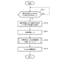
- step ST11 it is checked whether or not the tunnel flag of the link R1 at the current position is “1” (step ST11). That is, the navigation processing unit 25 calculates the current position using the current position calculation function, and checks whether the tunnel flag assigned to the link R1 where the calculated current position exists is “1”. If it is determined in this step ST11 that the tunnel flag of the link R1 is not “1”, it is recognized that it is not in the tunnel, and the standby state is entered while repeatedly executing this step ST11.
- Step ST12 the navigation processing unit 25 calculates the distance D1 from the current position to the node existing in the traveling direction of the link R1 with reference to the map information read from the HDD 23 via the control unit 27.
- the calculated distance D1 is stored in the navigation processing unit 25 and is referred to in the next tunnel distance calculation process.
- a tunnel distance calculation process in front of the link R1 is executed (step ST13).
- the link R1 and the distance D1 are passed to the tunnel distance calculation process as arguments. Details of the tunnel distance calculation processing will be described with reference to the flowchart shown in FIG. In the flowchart shown in FIG. 3, the process starts with the reference link A and the accumulated tunnel distance B specified as arguments. That is, R1 and D1 designated in step ST13 in FIG. 2 are started as arguments A and B in FIG.
- step ST21 it is checked whether or not the inspection of all links connected to the node in the traveling direction of the link A has been completed. That is, the navigation processing unit 25 refers to the map information read from the HDD 23 via the control unit 27, and whether or not the inspection for all of the plurality of links connected to the nodes existing in the traveling direction of the link A has been completed. Check out. If it is determined in step ST21 that the inspection of all the links connected to the node in the traveling direction of link A is completed, the sequence returns to the main process, and then the main process ends.
- step ST21 if it is determined in step ST21 that the inspection of all the links connected to the node in the traveling direction of link A has not been completed, then one of the uninspected links is selected (step ST21). ST22). That is, the navigation processing unit 25 selects one link from a plurality of links connected to the nodes existing in the traveling direction of the link R1. In the following steps, the link selected here is referred to as R2.
- step ST23 it is checked whether or not the link R2 can pass in the traveling direction. That is, the navigation processing unit 25 refers to the travelable direction information added to the link R2 selected in step ST22 to check whether the link R2 can pass in the traveling direction. If it is determined in step ST23 that the vehicle cannot travel in the traveling direction, the sequence returns to step ST21 and the above-described processing is repeated. Thereby, the link etc. for which entry is prohibited are removed from the processing target.
- step ST23 if it is determined in step ST23 that the link R2 can pass in the traveling direction, it is then checked whether the link R2 is the link A (step ST24). If it is determined in step ST24 that R2 is the link A, the sequence returns to step ST21 and the above-described processing is repeated. As a result, the link corresponding to the progress of making a U-turn in the tunnel is removed from the processing target.
- step ST24 If it is determined in step ST24 that the link R2 is not the link A, it is then checked whether the tunnel flag of the link R2 is “1” (step ST25). That is, the navigation processing unit 25 checks whether the tunnel flag added to the link R2 selected in step ST22 is “1”.
- step ST25 If it is determined in this step ST25 that the tunnel flag of the link R2 is “1”, it is recognized that the node existing in the traveling direction of the link R2 is not the end point of the tunnel, and the link length of the link R2 at the distance B Are added to calculate the distance D2 (step ST26). That is, the navigation processing unit 25 adds the link length of the link R2 acquired from the map information to the distance B calculated in step ST12 of the main process. Thereby, the distance D2 from the current position to the node existing in the traveling direction of the link R2 is calculated.
- a tunnel distance calculation process in front of the link R2 is executed (step ST27).
- the link R2 and the distance D2 are passed to the tunnel distance calculation process as arguments.
- This tunnel distance calculation process is the same as the tunnel distance calculation process ahead of the link R1 described above except that the link R2 and the distance D2 are used as arguments.
- the sequence returns to the main process, and then the main process ends. If the tunnel end point is not detected in the tunnel distance calculation process ahead of the link R2 in step ST27, the process is similarly performed while increasing the nesting level of the tunnel distance calculation process until the tunnel end point is detected. Is executed.
- step ST25 If it is determined in step ST25 that the tunnel flag of the link R2 is not “1”, it is recognized that the node existing in the traveling direction of the link R2 is the tunnel end point, and the distance D2 is the distance to the tunnel end point. (Step ST28). That is, the distance D2 calculated in step ST26 is output as the tunnel distance from the current position to the node existing in the traveling direction of the link R2. When there is no branch in the tunnel, the distance D1 is output as the tunnel distance. Thereafter, the sequence returns to step ST21 and the above-described processing is repeated.
- tunnel information is then displayed (step ST14). That is, the navigation processing unit 25 sends data representing the tunnel distance obtained by the tunnel distance calculation process to the output control unit 26 via the control unit 27.
- the output control unit 26 generates an image in which the tunnel remaining distance indicated by the received data representing the tunnel distance is superimposed on the map, and sends it to the display device 15 as a video signal.
- the remaining distance to the tunnel exit is displayed on a part of the screen of the display device 15.
- FIG. 4 shows a display example when the tunnel branches into two, but when the tunnel branches into three or more, the remaining distance to each tunnel exit is displayed.
- the output control unit 26 can be configured to further generate an audio signal based on the received data representing the tunnel distance and send it to the audio output device 16. Thereby, the remaining distance from the audio output device 16 to each tunnel exit is output as audio.
- the map information processing apparatus According to the map information processing apparatus according to the first embodiment of the present invention, even when the tunnel enters a tunnel, even if it is a complicated tunnel that branches inside, it can reach all tunnel exits. Since the distance is displayed, the driver's psychological burden due to not knowing the distance to the tunnel exit can be reduced.
- FIG. 2 The map information processing apparatus according to the second embodiment of the present invention displays only the distance to the tunnel end point included in the recommended route even when the tunnel branches.
- the configuration of the map information processing apparatus according to Embodiment 2 of the present invention is the same as that of the map information processing apparatus according to Embodiment 1 shown in FIG.
- FIG. 5 is a flowchart showing a tunnel distance calculation process performed in the tunnel display process.
- the steps used to execute the same or equivalent process as the tunnel distance calculation process of the map information processing apparatus according to the first embodiment shown in the flowchart of FIG. Simplify the description.
- step ST21 it is checked whether or not the inspection of all links connected to the node in the traveling direction of the link A has been completed. If it is determined in step ST21 that the inspection of all the links connected to the node in the traveling direction of link A is completed, the sequence returns to the main process, and then the main process ends.
- step ST21 if it is determined in step ST21 that the inspection of all the links connected to the node in the traveling direction of link A has not been completed, then one of the uninspected links is selected (step ST21). ST22). In the following steps, the link selected here is referred to as R2.
- step ST31 it is checked whether or not the link R2 is included in the current recommended route. That is, the navigation processing unit 25 collates the data of the link R2 selected in step ST22 with the route data read from the RAM 24 via the control unit 27, thereby determining whether the link R2 is included in the current recommended route. Check out. If it is determined in step ST31 that the link R2 is not included in the current recommended route, the sequence returns to step ST21 and the above-described processing is repeated. As a result, links other than the links constituting the recommended route are excluded from the processing targets.
- step ST31 if it is determined in step ST31 that the link R2 is included in the current recommended route, it is then checked whether or not the tunnel flag of the link R2 is “1” (step ST25). If it is determined in this step ST25 that the tunnel flag of the link R2 is “1”, it is recognized that the node existing in the traveling direction of the link R2 is not the end point of the tunnel, and the link length of the link R2 at the distance B Are added to calculate the distance D2 (step ST26). Next, a tunnel distance calculation process in front of the link R2 is executed (step ST27). When the tunnel distance calculation process ahead of the link R2 in step ST27 ends, the sequence returns to the main process, and then the main process ends.
- step ST25 When it is determined in step ST25 that the tunnel flag of the link R2 is not “1”, it is recognized that the node existing in the traveling direction of the link R2 is the tunnel end point, and the distance B is the distance to the tunnel end point. (Step ST28). Thereafter, the sequence returns to step ST21 and the above-described processing is repeated.
- the map information processing apparatus of the second embodiment of the present invention when entering the tunnel while traveling along the recommended route, the remaining road to the tunnel exit on the recommended route is displayed. Since the distance is displayed, the driver's psychological burden due to not knowing the remaining distance to the tunnel exit can be reduced. Moreover, since only the remaining distance to one tunnel exit existing on the recommended route needs to be calculated, the processing load can be reduced as compared with the map information processing apparatus according to the first embodiment.
- Embodiment 3 The map information processing apparatus according to the third embodiment of the present invention displays only the distance to the tunnel end point that can be reached by one branch when the tunnel branches.
- the configuration of the map information processing apparatus according to Embodiment 3 of the present invention is the same as that of the map information processing apparatus according to Embodiment 1 shown in FIG.
- step ST11 it is checked whether or not the tunnel flag of the link R1 at the current position is “1” (step ST11). If it is determined in this step ST11 that the tunnel flag of the link R1 is not “1”, it is recognized that it is not in the tunnel, and the standby state is entered while repeatedly executing this step ST11.
- step ST11 If it is determined that the tunnel flag of the link R1 is “1” in the standby state by repeatedly executing this step ST11, it is recognized that the tunnel is in the tunnel, and then the node in the traveling direction of the link R1 from the current position. Distance D1 is calculated (step ST12).
- step ST41 the branch count J is set to “0” (step ST41). That is, the navigation processing unit 25 initializes the number of branches J held therein to “0”.
- a tunnel distance calculation process in front of the link R1 is executed (step ST42).
- the link R1, the distance D1, and the branch count J are passed to the tunnel distance calculation process as arguments.
- the details of the tunnel distance calculation process will be described with reference to the flowchart shown in FIG. In the following, the steps used to execute the same or equivalent process as the tunnel distance calculation process of the map information processing apparatus according to the first embodiment shown in the flowchart of FIG. Simplify the description.
- the navigation processing unit 25 refers to the map information read from the HDD 23 via the control unit 27, and is a link that is connected to a node existing in the traveling direction of the link A and can pass in the traveling direction. It is checked whether or not there is only one link with the flag “1”.
- step ST51 If it is determined in this step ST51 that there is only one link having a tunnel flag “1” that can be passed in the traveling direction connected to the node in the traveling direction of the link A, the sequence proceeds to step ST53.
- step ST51 if it is determined that there is not only one link having a tunnel flag “1” that can be passed in the traveling direction connected to the node in the traveling direction of link A, then the branch count J is “ It is checked whether it is smaller than 1 ”(step ST52). That is, the navigation processing unit 25 checks whether the branch count J is “0”.
- step ST52 if it is determined that the number of branches J is not smaller than “1”, that is, “1” or more, it is recognized that it is the second branch, and the tunnel distance calculation process is terminated and the sequence is completed. Returns to the main process, and then the main process ends. On the other hand, if it is determined in step ST52 that the number of branches J is smaller than “1”, it is recognized that this is the first branch, and the sequence proceeds to step ST53.
- step ST53 one link is selected from the links having the tunnel flag “1” that can pass in the traveling direction connected to the node in the traveling direction of the link A, and is set as the link R2. That is, the navigation processing unit 25 executes the following process using one of the links having the tunnel flag “1” that is connected to the node in the traveling direction of the link A and that has the link flag “1” as the link R2.
- step ST23 it is checked whether or not the link R2 can pass in the traveling direction. If it is determined in step ST23 that the vehicle cannot travel in the traveling direction, the sequence returns to step ST51 and the above-described processing is repeated. Thereby, the link for which entry is prohibited is removed from the processing target.
- step ST23 if it is determined in step ST23 that the link R2 can pass in the traveling direction, it is then checked whether the link R2 is the link A (step ST24). If it is determined in step ST24 that R2 is the link A, the sequence returns to step ST51, and the above-described processing is repeated. As a result, the link corresponding to the progress of making a U-turn in the tunnel is removed from the processing target.
- step ST24 If it is determined in step ST24 that the link R2 is not the link A, it is then checked whether the tunnel flag of the link R2 is “1” (step ST25). If it is determined in this step ST25 that the tunnel flag of the link R2 is “1”, it is recognized that the node existing in the traveling direction of the link R2 is not the end point of the tunnel, and the link length of the link R2 at the distance B Are added to calculate the distance D2 (step ST26). Next, “1” is added to the branch count J (step ST54). That is, the navigation processing unit 25 adds “1” to the branch count J held at that time.
- a tunnel distance calculation process in front of the link R2 is executed (step ST55).
- the link R1, the distance D1, and the branch count J are passed to the tunnel distance calculation process as arguments.
- This tunnel distance calculation process is the same as the tunnel distance calculation process ahead of the link R1 described above, except that the link R2, the distance D2, and the number of branches J are used as arguments. If it is determined that the number of branches J in step ST55 is not smaller than “1”, the sequence returns to the main process, and then the main process ends.
- step ST25 When it is determined in step ST25 that the tunnel flag of the link R2 is not “1”, it is recognized that the node existing in the traveling direction of the link R2 is the tunnel end point, and the distance B is the distance to the tunnel end point. (Step ST28). Thereafter, the sequence returns to step ST51, and the above-described processing is repeated.
- tunnel information is then displayed (step ST14).
- tunnel information is then displayed (step ST14).
- the distance to the tunnel end point that can be reached by one branch is displayed on a part of the screen of the display device 15.
- the distance to the tunnel exit can be output by voice.
- the map information processing apparatus when entering the tunnel, only the distance to the tunnel end point that can be reached by one branch is displayed.
- the driver's psychological burden caused by not knowing the distance to the exit can be reduced.
- the processing load can be reduced as compared with the map information processing apparatus according to the first embodiment.
- the link branches into two links at the branch point P1, and one link branches into two links at the branch point P2.
- the other link branches into two links at the branch point P3 the distance to the tunnel exit is not displayed at the current position.
- the remaining distance of the tunnel is displayed when the vehicle travels between the branch point P1 and the branch point P2, so the driver's psychological burden due to not knowing the distance to the tunnel exit is reduced. it can.
- the distance to the tunnel exit is displayed or output by voice so as to notify the user. Can be displayed, or can be output by voice to notify the user.
- the navigation processing unit 25 divides the tunnel distance calculated in the above-described procedure by the speed included in the sensor information sent from the sensor information input unit 22 via the control unit 27 to reach the tunnel exit. It can be configured to calculate time.
- the map information storage device displays the distances to all tunnel exits even when the tunnel enters a tunnel, even if it is a complex tunnel that branches inside. Because it can reduce the driver's psychological burden caused by not knowing, it relates to a map information processing device that processes map information in navigation devices, etc., especially when outputting information about the tunnel exit when traveling through a tunnel that branches internally Suitable for
Landscapes
- Engineering & Computer Science (AREA)
- Radar, Positioning & Navigation (AREA)
- Remote Sensing (AREA)
- Automation & Control Theory (AREA)
- Physics & Mathematics (AREA)
- General Physics & Mathematics (AREA)
- Navigation (AREA)
- Instructional Devices (AREA)
Abstract
Priority Applications (4)
| Application Number | Priority Date | Filing Date | Title |
|---|---|---|---|
| DE112009004047.0T DE112009004047B4 (de) | 2009-02-17 | 2009-11-10 | Karteninformations -Verarbeitungsvorrichtung |
| JP2011500369A JP5153937B2 (ja) | 2009-02-17 | 2009-11-10 | 地図情報処理装置 |
| CN200980157282.3A CN102317740B (zh) | 2009-02-17 | 2009-11-10 | 地图信息处理装置 |
| US13/131,697 US8532926B2 (en) | 2009-02-17 | 2009-11-10 | Map information processing device |
Applications Claiming Priority (2)
| Application Number | Priority Date | Filing Date | Title |
|---|---|---|---|
| JP2009033898 | 2009-02-17 | ||
| JP2009-033898 | 2009-02-17 |
Publications (1)
| Publication Number | Publication Date |
|---|---|
| WO2010095193A1 true WO2010095193A1 (fr) | 2010-08-26 |
Family
ID=42633495
Family Applications (1)
| Application Number | Title | Priority Date | Filing Date |
|---|---|---|---|
| PCT/JP2009/005984 Ceased WO2010095193A1 (fr) | 2009-02-17 | 2009-11-10 | Dispositif de traitement d'informations cartographiques |
Country Status (5)
| Country | Link |
|---|---|
| US (1) | US8532926B2 (fr) |
| JP (1) | JP5153937B2 (fr) |
| CN (1) | CN102317740B (fr) |
| DE (1) | DE112009004047B4 (fr) |
| WO (1) | WO2010095193A1 (fr) |
Families Citing this family (5)
| Publication number | Priority date | Publication date | Assignee | Title |
|---|---|---|---|---|
| US20120127012A1 (en) * | 2010-11-24 | 2012-05-24 | Samsung Electronics Co., Ltd. | Determining user intent from position and orientation information |
| JP5999488B2 (ja) * | 2012-07-30 | 2016-09-28 | アイシン・エィ・ダブリュ株式会社 | 端末装置及び案内プログラム |
| KR20150041946A (ko) * | 2013-10-10 | 2015-04-20 | 현대자동차주식회사 | 음영지역 안내 장치 및 방법 |
| JP6720893B2 (ja) * | 2017-02-28 | 2020-07-08 | 京セラドキュメントソリューションズ株式会社 | 画像形成装置 |
| US11645908B2 (en) * | 2018-06-18 | 2023-05-09 | Roger Andre EILERTSEN | Road tunnel security system |
Citations (4)
| Publication number | Priority date | Publication date | Assignee | Title |
|---|---|---|---|---|
| JP2001033261A (ja) * | 1999-07-21 | 2001-02-09 | Matsushita Electric Ind Co Ltd | カーナビゲーション装置及びその道路案内表示方法 |
| JP2001165680A (ja) * | 1999-12-07 | 2001-06-22 | Kenwood Corp | ナビゲーション装置、営業状況表示方法及び記録媒体 |
| JP2003240575A (ja) * | 2002-02-15 | 2003-08-27 | Sony Corp | ナビゲーション装置およびナビゲーション方法 |
| JP2007163274A (ja) * | 2005-12-13 | 2007-06-28 | Denso Corp | ナビゲーション装置 |
Family Cites Families (19)
| Publication number | Priority date | Publication date | Assignee | Title |
|---|---|---|---|---|
| DE19619643C1 (de) * | 1996-05-15 | 1997-07-17 | Daimler Benz Ag | Fahrzeug mit Navigationseinrichtung |
| JP3582560B2 (ja) * | 1997-07-08 | 2004-10-27 | アイシン・エィ・ダブリュ株式会社 | 車両用ナビゲーション装置及び記録媒体 |
| JP3791139B2 (ja) * | 1997-07-30 | 2006-06-28 | 株式会社デンソー | 車両用制御装置 |
| EP1120631B1 (fr) * | 1999-07-06 | 2008-12-24 | Mitsubishi Denki Kabushiki Kaisha | Dispositif de navigation |
| US7302339B2 (en) * | 2003-07-21 | 2007-11-27 | Justin Gray | Hazard countermeasure system and method for vehicles |
| EP1732043A4 (fr) * | 2004-03-31 | 2010-02-10 | Pioneer Corp | Méthode de traçage, programme de traçage et équipement de traçage |
| JP5139642B2 (ja) * | 2006-04-24 | 2013-02-06 | パイオニア株式会社 | 情報生成装置、情報生成処理プログラム及び情報生成方法 |
| JP4895313B2 (ja) * | 2006-04-28 | 2012-03-14 | パナソニック株式会社 | ナビゲーション装置およびその方法 |
| JP4923868B2 (ja) * | 2006-08-30 | 2012-04-25 | 株式会社デンソー | 自動制御装置 |
| JP2008096346A (ja) | 2006-10-13 | 2008-04-24 | Xanavi Informatics Corp | ナビゲーション装置、および避難経路の案内方法 |
| US20100023254A1 (en) * | 2006-11-10 | 2010-01-28 | Hiroshi Machino | Navigation system |
| JP4753999B2 (ja) * | 2006-12-18 | 2011-08-24 | 三菱電機株式会社 | ナビゲーション装置 |
| AU2007343335A1 (en) * | 2007-01-10 | 2008-07-17 | Tomtom International B.V. | Method of indicating traffic delays, computer program and navigation system therefor |
| DE102007020434B4 (de) * | 2007-04-19 | 2011-01-05 | Navigon Ag | Verfahren zum Betrieb einer Einrichtung |
| JP5225218B2 (ja) * | 2008-07-02 | 2013-07-03 | パナソニック株式会社 | 車両搭載型画像記録装置および画像記録方法 |
| JP4738550B2 (ja) * | 2009-02-16 | 2011-08-03 | 三菱電機株式会社 | 地図情報処理装置 |
| JPWO2010095197A1 (ja) * | 2009-02-18 | 2012-08-16 | 三菱電機株式会社 | 地図情報処理装置 |
| JP5051550B2 (ja) * | 2009-02-26 | 2012-10-17 | アイシン・エィ・ダブリュ株式会社 | ナビゲーション装置及びナビゲーション用プログラム |
| JP5551896B2 (ja) * | 2009-06-29 | 2014-07-16 | 株式会社日立製作所 | ナビゲーション装置、経路探索サーバ、および経路探索システム |
-
2009
- 2009-11-10 WO PCT/JP2009/005984 patent/WO2010095193A1/fr not_active Ceased
- 2009-11-10 CN CN200980157282.3A patent/CN102317740B/zh not_active Expired - Fee Related
- 2009-11-10 DE DE112009004047.0T patent/DE112009004047B4/de not_active Expired - Fee Related
- 2009-11-10 JP JP2011500369A patent/JP5153937B2/ja not_active Expired - Fee Related
- 2009-11-10 US US13/131,697 patent/US8532926B2/en not_active Expired - Fee Related
Patent Citations (4)
| Publication number | Priority date | Publication date | Assignee | Title |
|---|---|---|---|---|
| JP2001033261A (ja) * | 1999-07-21 | 2001-02-09 | Matsushita Electric Ind Co Ltd | カーナビゲーション装置及びその道路案内表示方法 |
| JP2001165680A (ja) * | 1999-12-07 | 2001-06-22 | Kenwood Corp | ナビゲーション装置、営業状況表示方法及び記録媒体 |
| JP2003240575A (ja) * | 2002-02-15 | 2003-08-27 | Sony Corp | ナビゲーション装置およびナビゲーション方法 |
| JP2007163274A (ja) * | 2005-12-13 | 2007-06-28 | Denso Corp | ナビゲーション装置 |
Also Published As
| Publication number | Publication date |
|---|---|
| US20110231089A1 (en) | 2011-09-22 |
| US8532926B2 (en) | 2013-09-10 |
| DE112009004047B4 (de) | 2015-02-12 |
| DE112009004047T5 (de) | 2012-05-31 |
| JP5153937B2 (ja) | 2013-02-27 |
| CN102317740B (zh) | 2014-04-09 |
| CN102317740A (zh) | 2012-01-11 |
| JPWO2010095193A1 (ja) | 2012-08-16 |
Similar Documents
| Publication | Publication Date | Title |
|---|---|---|
| US8325180B2 (en) | Method for changing dynamic display mode and apparatus thereof in car navigation system | |
| US20100268453A1 (en) | Navigation device | |
| JP2006084208A (ja) | ナビゲーション装置及び進行方向案内方法 | |
| JP4361595B2 (ja) | ナビゲーション装置、並びに経路誘導方法及びプログラム | |
| JP5153937B2 (ja) | 地図情報処理装置 | |
| JP4738550B2 (ja) | 地図情報処理装置 | |
| JP2018128466A (ja) | ナビゲーション装置、ヘッドアップディスプレイ、制御方法、プログラム、及び記憶媒体 | |
| JP2015105903A (ja) | ナビゲーション装置、ヘッドアップディスプレイ、制御方法、プログラム、及び記憶媒体 | |
| WO2010095197A1 (fr) | Dispositif de traitement d'informations cartographiques | |
| JP2011043383A (ja) | ナビゲーション装置、ナビゲーション方法、およびプログラム | |
| JPWO2007105540A1 (ja) | ナビゲーション装置及びナビゲーション方法 | |
| US7593810B2 (en) | Interactive route guide device | |
| JP2007140033A (ja) | ナビゲーション装置およびその交差点拡大図表示方法 | |
| JP5041410B2 (ja) | ナビゲーション装置 | |
| JP2023126324A (ja) | ナビゲーション装置、ヘッドアップディスプレイ、制御方法、プログラム、及び記憶媒体 | |
| JP4169613B2 (ja) | ナビゲーション装置 | |
| JP2008292395A (ja) | 車載用ナビゲーション装置 | |
| JP2006250674A (ja) | 目的地の音声案内制御装置および音声案内制御プログラム | |
| JP2007003365A (ja) | 車載用ナビゲーション装置及び車載用ナビゲーション装置の経路探索方法。 | |
| JP2007048012A (ja) | フレーム取得装置、動画データ構造、地図データ及び車載用ナビゲーション装置 | |
| JP2011180067A (ja) | 運転支援装置 | |
| JP2006189310A (ja) | ナビゲーション装置 | |
| WO2014009992A1 (fr) | Dispositif de navigation | |
| JP2013170966A (ja) | 経路探索装置、制御方法、プログラム及び記憶媒体 | |
| JP2007256224A (ja) | ルート探索装置、その方法、そのプログラム及びその記録媒体 |
Legal Events
| Date | Code | Title | Description |
|---|---|---|---|
| WWE | Wipo information: entry into national phase |
Ref document number: 200980157282.3 Country of ref document: CN |
|
| 121 | Ep: the epo has been informed by wipo that ep was designated in this application |
Ref document number: 09840300 Country of ref document: EP Kind code of ref document: A1 |
|
| WWE | Wipo information: entry into national phase |
Ref document number: 2011500369 Country of ref document: JP |
|
| WWE | Wipo information: entry into national phase |
Ref document number: 13131697 Country of ref document: US |
|
| WWE | Wipo information: entry into national phase |
Ref document number: 112009004047 Country of ref document: DE Ref document number: 1120090040470 Country of ref document: DE |
|
| 122 | Ep: pct application non-entry in european phase |
Ref document number: 09840300 Country of ref document: EP Kind code of ref document: A1 |