WO2010100965A1 - Dispositif de régulation de température de catalyseur - Google Patents
Dispositif de régulation de température de catalyseur Download PDFInfo
- Publication number
- WO2010100965A1 WO2010100965A1 PCT/JP2010/050564 JP2010050564W WO2010100965A1 WO 2010100965 A1 WO2010100965 A1 WO 2010100965A1 JP 2010050564 W JP2010050564 W JP 2010050564W WO 2010100965 A1 WO2010100965 A1 WO 2010100965A1
- Authority
- WO
- WIPO (PCT)
- Prior art keywords
- combustion
- target
- exhaust gas
- fuel supply
- catalyst
- Prior art date
- Legal status (The legal status is an assumption and is not a legal conclusion. Google has not performed a legal analysis and makes no representation as to the accuracy of the status listed.)
- Ceased
Links
Images






Classifications
-
- F—MECHANICAL ENGINEERING; LIGHTING; HEATING; WEAPONS; BLASTING
- F02—COMBUSTION ENGINES; HOT-GAS OR COMBUSTION-PRODUCT ENGINE PLANTS
- F02D—CONTROLLING COMBUSTION ENGINES
- F02D41/00—Electrical control of supply of combustible mixture or its constituents
- F02D41/02—Circuit arrangements for generating control signals
- F02D41/021—Introducing corrections for particular conditions exterior to the engine
- F02D41/0235—Introducing corrections for particular conditions exterior to the engine in relation with the state of the exhaust gas treating apparatus
- F02D41/024—Introducing corrections for particular conditions exterior to the engine in relation with the state of the exhaust gas treating apparatus to increase temperature of the exhaust gas treating apparatus
-
- F—MECHANICAL ENGINEERING; LIGHTING; HEATING; WEAPONS; BLASTING
- F02—COMBUSTION ENGINES; HOT-GAS OR COMBUSTION-PRODUCT ENGINE PLANTS
- F02D—CONTROLLING COMBUSTION ENGINES
- F02D35/00—Controlling engines, dependent on conditions exterior or interior to engines, not otherwise provided for
- F02D35/02—Controlling engines, dependent on conditions exterior or interior to engines, not otherwise provided for on interior conditions
- F02D35/028—Controlling engines, dependent on conditions exterior or interior to engines, not otherwise provided for on interior conditions by determining the combustion timing or phasing
-
- F—MECHANICAL ENGINEERING; LIGHTING; HEATING; WEAPONS; BLASTING
- F02—COMBUSTION ENGINES; HOT-GAS OR COMBUSTION-PRODUCT ENGINE PLANTS
- F02D—CONTROLLING COMBUSTION ENGINES
- F02D41/00—Electrical control of supply of combustible mixture or its constituents
- F02D41/30—Controlling fuel injection
- F02D41/38—Controlling fuel injection of the high pressure type
- F02D41/40—Controlling fuel injection of the high pressure type with means for controlling injection timing or duration
- F02D41/402—Multiple injections
-
- Y—GENERAL TAGGING OF NEW TECHNOLOGICAL DEVELOPMENTS; GENERAL TAGGING OF CROSS-SECTIONAL TECHNOLOGIES SPANNING OVER SEVERAL SECTIONS OF THE IPC; TECHNICAL SUBJECTS COVERED BY FORMER USPC CROSS-REFERENCE ART COLLECTIONS [XRACs] AND DIGESTS
- Y02—TECHNOLOGIES OR APPLICATIONS FOR MITIGATION OR ADAPTATION AGAINST CLIMATE CHANGE
- Y02T—CLIMATE CHANGE MITIGATION TECHNOLOGIES RELATED TO TRANSPORTATION
- Y02T10/00—Road transport of goods or passengers
- Y02T10/10—Internal combustion engine [ICE] based vehicles
- Y02T10/12—Improving ICE efficiencies
-
- Y—GENERAL TAGGING OF NEW TECHNOLOGICAL DEVELOPMENTS; GENERAL TAGGING OF CROSS-SECTIONAL TECHNOLOGIES SPANNING OVER SEVERAL SECTIONS OF THE IPC; TECHNICAL SUBJECTS COVERED BY FORMER USPC CROSS-REFERENCE ART COLLECTIONS [XRACs] AND DIGESTS
- Y02—TECHNOLOGIES OR APPLICATIONS FOR MITIGATION OR ADAPTATION AGAINST CLIMATE CHANGE
- Y02T—CLIMATE CHANGE MITIGATION TECHNOLOGIES RELATED TO TRANSPORTATION
- Y02T10/00—Road transport of goods or passengers
- Y02T10/10—Internal combustion engine [ICE] based vehicles
- Y02T10/40—Engine management systems
Definitions
- the present invention relates to a catalyst temperature control device that controls the temperature of a catalyst that purifies exhaust gas discharged from an internal combustion engine.
- Patent Document 1 As a conventional temperature control device of this type, for example, one disclosed in Patent Document 1 is known.
- this temperature control device when the catalyst is not activated, the fuel supply to the internal combustion engine is divided into three times, thereby raising the temperature of the catalyst by raising the temperature of the exhaust gas.
- the fuel supply timing at this time is set so that the interval of fuel supply between the first and second times and the interval of fuel supply between the second and third times become the same constant interval.
- the fuel supply is performed only at a constant interval, and therefore, depending on the operating state of the internal combustion engine, combustion is performed between a plurality of combustion periods corresponding to a plurality of combustion periods.
- the start timing of may vary. In that case, since the combustion state fluctuates in the whole of a plurality of combustion periods, the temperature of the exhaust gas can not be accurately controlled.
- the temperature of the catalyst when the temperature of the exhaust gas is too low, the temperature of the catalyst can not be raised promptly, so that the catalyst can not be activated quickly, and the exhaust gas characteristics deteriorate, and the temperature of the exhaust gas is too high. As described above, since the amount of unburned fuel in the exhaust gas increases, the exhaust gas characteristics also deteriorate.
- the present invention has been made to solve such problems, and it is an object of the present invention to provide a catalyst temperature control device capable of maintaining the exhaust gas characteristics well and rapidly activating the catalyst. .
- the invention according to claim 1 of the present invention is a temperature control device 1 of a catalyst 10 for controlling the temperature of a catalyst 10 for purifying an exhaust gas discharged from an internal combustion engine 3.
- the fuel supply means fuel supply means (in the embodiment, hereinafter the same in the present paragraph) injector 4 and ECU 2) for dividing the fuel into multiple times and detecting the operating state of the internal combustion engine 3 (crank angle sensor 26, the air flow sensor 22, the intake air temperature sensor 23, the intake pressure sensor 24, the EGR amount sensor 25, the ECU 2), and the detected operating state of the internal combustion engine 3 (catalyst temperature TCAT, required torque PMCMD, engine speed NE, intake air Amount QA, intake temperature TA, intake pressure PB, EGR amount QEGR, fuel pressure PF, fuel properties, warm-up state of the engine 3 and energization state of the glow plug 11)
- fuel supply timing setting means ECU 2 for setting a plurality of fuel supply timings (first to fifth fuel injection timings TINJ
- the fuel supply means divides the fuel supply to the internal combustion engine a plurality of times.
- the temperature of the exhaust gas is increased, and the temperature of the catalyst is increased.
- the plurality of fuel supply timings are set in accordance with the detected operating state of the internal combustion engine.
- the unburned fuel contained in the exhaust gas changes in accordance with the temperature of the exhaust gas.
- the timing at which combustion starts in a plurality of combustion periods corresponding to a plurality of fuel supplies depends on the fuel supply timing.
- the relationship between the fuel supply timing and the combustion start timing changes according to the operating state of the internal combustion engine. Therefore, each combustion start timing can be controlled to an appropriate timing according to the operating state of the internal combustion engine by setting the plurality of fuel supply timings in accordance with the detected operating state of the internal combustion engine.
- a stable combustion state can be maintained throughout the plurality of combustion periods, and the temperature of the exhaust gas and hence the temperature of the catalyst can be appropriately controlled.
- the catalyst when the catalyst is not activated, the amount of unburned fuel discharged to the atmosphere can be reduced, and the catalyst can be rapidly activated while maintaining good exhaust gas characteristics.
- the catalyst when the catalyst is in an active state, the emission of unburned fuel to the atmosphere is maximized to maintain the temperature of the exhaust gas as low as possible while maintaining the temperature and purification capacity of the catalyst appropriately. It is possible to reduce the exhaust gas characteristics. In addition, the amount of fuel consumption can be reduced as much as unnecessary increase in the temperature of the exhaust gas can be avoided.
- Target combustion start timing setting means a plurality of target combustion start timings (first to fifth target combustion timings TIG1 to TIG5) serving as targets of combustion start timings at which combustion starts in the first to fifth combustion periods
- the ignition delay periods first to fifth ignition delay periods IGL1 to IGL5 of the plurality of combustions corresponding to the fuel supply of a plurality of times are calculated.
- the fuel supply timing setting means further includes a plurality of ignition delay periods corresponding to the plurality of target combustion start timings. By subtracting respectively, and sets a plurality of fuel supply timing.
- the plurality of target combustion start timings in the plurality of combustion periods corresponding to the plurality of fuel supplies are set according to the operation state of the internal combustion engine, and the plurality of target combustion start timings are performed according to the operation state of the internal combustion engine.
- a plurality of combustion ignition delay periods corresponding to the fuel supply are calculated.
- a plurality of fuel supply timings are set by respectively subtracting a plurality of corresponding ignition delay periods from a plurality of target combustion start timings.
- the relationship between the fuel supply timing and the combustion start timing changes in accordance with the operating state of the internal combustion engine. This is because the ignition delay period of combustion changes according to the operating state of the internal combustion engine. Therefore, as described above, while setting a plurality of target combustion start timings according to the detected operation state of the internal combustion engine, a plurality of ignition delay periods are calculated, and a plurality of fuel supply timings are set using both of them. By doing this, actual combustion can be started at the set appropriate target combustion start timing. As a result, the temperature of the exhaust gas and hence the temperature of the catalyst can be properly controlled, so that the characteristics of the exhaust gas can be maintained better and the catalyst can be rapidly activated.
- the invention according to claim 3 is the temperature control device 1 of the catalyst 10 for controlling the temperature of the catalyst 10 for purifying the exhaust gas discharged from the internal combustion engine 3, and the fuel is divided and supplied to the internal combustion engine 3 multiple times. Timing at which combustion is started in a plurality of combustion periods (first to fifth combustion periods) corresponding to a plurality of fuel supplies by the fuel supply means (injector 4, ECU 2) and the fuel supply means The combustion start timing calculation means (ECU 2, steps 73, 79, 86, 93, 100 in FIGS.
- the fuel supply means divides the fuel supply to the internal combustion engine a plurality of times. This raises the temperature of the exhaust gas and raises the temperature of the catalyst. Further, timings at which combustion has started in a plurality of combustion periods corresponding to a plurality of times of fuel supply are calculated as a plurality of combustion start timings. Furthermore, in accordance with the detected operating state of the internal combustion engine, a plurality of target combustion start timings that are targets of the respective combustion start timings are set. Then, a plurality of fuel supply timings are set by feedback control such that the plurality of combustion start timings respectively correspond to the corresponding target combustion start timings.
- the unburned fuel contained in the exhaust gas changes in accordance with the temperature of the exhaust gas.
- the actual target combustion start timing calculated in each combustion period is set according to the detected operating state of the internal combustion engine. Since the fuel supply timing is set as follows, each combustion start timing can be controlled to an appropriate timing according to the operating state of the internal combustion engine. As a result, a stable combustion state can be maintained throughout the plurality of combustion periods, and the temperature of the exhaust gas and hence the temperature of the catalyst can be appropriately controlled. As a result, when the catalyst is not activated, the amount of unburned fuel discharged to the atmosphere can be reduced, and the catalyst can be rapidly activated while maintaining good exhaust gas characteristics.
- the temperature of the exhaust gas can be maintained as low as possible while appropriately maintaining the temperature and purification capacity of the catalyst, so the amount of unburned fuel discharged into the atmosphere can be reduced. It can be reduced to the maximum, whereby the exhaust gas characteristics can be kept good. In addition, the amount of fuel consumption can be reduced as much as unnecessary increase in the temperature of the exhaust gas can be avoided.
- the target combustion start timing setting means is plural so that combustion is continuously performed between a plurality of combustion periods. Setting a target combustion start timing of
- each target combustion start timing is set such that combustion is continuously performed between the plurality of combustion periods. Therefore, by setting the plurality of fuel supply timings so that each combustion start timing corresponds to the corresponding target combustion start timing, the combustion can be performed without interruption throughout the plurality of combustion periods. As a result, a more stable combustion state can be secured, and the exhaust gas characteristics can be well maintained, and the catalyst can be rapidly activated.
- target exhaust gas temperature setting means ECU 2
- the method further includes the steps 23, 34) of FIG. 4, and the target combustion start timing setting means sets the plurality of target combustion start timings such that the lengths of the plurality of combustion periods become longer as the set target exhaust gas temperature TEMCMD becomes higher. To set.
- the plurality of target combustion start timings are set such that the length of each combustion period becomes longer as the set target exhaust gas temperature is higher.
- the temperature of the exhaust gas is higher because the entire combustion period in which combustion is performed in one combustion cycle is also longer. Therefore, as described above, by setting the target combustion start timing so that the length of each combustion period is longer as the target exhaust gas temperature is higher, the temperature of the exhaust gas is appropriately controlled according to the temperature of the catalyst. be able to. As a result, the exhaust gas characteristics can be maintained better, and the catalyst can be rapidly activated.
- the fuel supply means executes the fuel supply in a predetermined period from the vicinity of the start of the expansion stroke to the end of the expansion stroke,
- the target combustion start timing setting means sets the plurality of target combustion start timings to be more retarded as the target exhaust gas temperature TEMCMD is higher.
- the plurality of fuel supplies are performed in a predetermined period from the vicinity of the start of the expansion stroke to the end.
- the temperature of the exhaust gas becomes higher as the fuel supply timing is more retarded.
- the plurality of target combustion start timings are set to be more retarded, so the temperature of the exhaust gas can be appropriately controlled according to the temperature of the catalyst, As a result, the exhaust gas characteristics can be maintained better, and the catalyst can be rapidly activated.
- the in-cylinder pressure detection means detects the pressure in the cylinder 3a of the internal combustion engine 3 as the in-cylinder pressure PCYL.
- the internal combustion pressure sensor 21) and heat release rate calculation means for calculating the heat release rate dQHR based on the detected in-cylinder pressure PCYL, and the combustion start timing calculation means calculates the heat release rate calculated A plurality of combustion start timings are calculated based on dQHR.
- the heat release rate is calculated based on the detected in-cylinder pressure.
- the heat release rate calculated in this manner has a high correlation with the combustion state of the fuel. Therefore, based on the heat release rate, a plurality of combustion start timings can be appropriately calculated, and by setting the fuel supply timing using the combustion start timings calculated in this manner, the temperature of the exhaust gas can be appropriately set.
- the catalyst can be rapidly activated while being able to be controlled and maintaining the exhaust gas characteristics well.
- the invention according to claim 8 is the temperature control device 1 of the catalyst 10 for controlling the temperature of the catalyst 10 for purifying the exhaust gas discharged from the internal combustion engine 3, and the fuel is divided and supplied to the internal combustion engine 3 plural times.
- Fuel supply means injector 4, ECU 2), in-cylinder pressure detection means (in-cylinder pressure sensor 21) for detecting the pressure in the cylinder 3a of the internal combustion engine 3 as the in-cylinder pressure PCYL, and According to the heat release rate calculation means (ECU 2) for calculating the heat release rate dQHR and the timing for supplying the fuel by the fuel supply means according to the convergence state of the calculated heat release rate dQHR, a plurality of fuel supply timings are set. And fuel supply timing setting means (ECU 2).
- the fuel supply means divides the fuel supply to the internal combustion engine a plurality of times, thereby raising the temperature of the exhaust gas and raising the temperature of the catalyst. Also, a plurality of fuel supply timings are set according to the convergence state of the heat release rate calculated based on the detected in-cylinder pressure.
- Fluctuations in the combustion state throughout the plurality of combustion periods change the temperature of the exhaust gas. Also, at the end of fuel combustion, the heat release rate decreases and converges. According to the present invention, since the plurality of fuel supply timings are set according to the convergence state of the heat release rate, the combustion can be performed without interruption throughout the plurality of combustion periods. As a result, a stable combustion state can be secured, and the temperature of the exhaust gas, and hence the temperature of the catalyst, can be properly controlled. As a result, when the catalyst is not activated, the amount of unburned fuel discharged to the atmosphere can be reduced, and the catalyst can be rapidly activated while maintaining good exhaust gas characteristics.
- the temperature of the exhaust gas can be maintained as low as possible while appropriately maintaining the temperature and purification capacity of the catalyst, so the amount of unburned fuel discharged into the atmosphere can be reduced. It can be reduced to the maximum, whereby the exhaust gas characteristics can be kept good. In addition, the amount of fuel consumption can be reduced as much as unnecessary increase in the temperature of the exhaust gas can be avoided.
- target exhaust gas temperature setting means ECU 2 for setting target exhaust gas temperature TEMCMD to be a target of exhaust gas temperature.
- the fuel supply timing setting means supplies a plurality of fuels so that the higher the set target exhaust gas temperature TEMCMD, the later the combustion start timing before the convergence time of the heat release rate dQHR. It is characterized by setting a timing.
- the fuel supply is performed such that the combustion starts before the heat generation rate convergence timing and later. If the fuel supply is performed so that the start timing of the combustion is delayed, the temperature of the exhaust gas becomes high because the entire combustion period in which the combustion is performed in one combustion cycle becomes longer. Therefore, as described above, each combustion period is set longer by performing fuel supply so that the combustion starts at a later timing before the heat release rate converges and the target exhaust gas temperature is higher. It is possible to burn the supplied fuel with certainty. As a result, combustion can be reliably performed without interruption over the plurality of combustion periods while suppressing the amount of unburned fuel discharged.
- the temperature of the exhaust gas can be appropriately raised according to the target exhaust gas temperature by prolonging the entire combustion period in one combustion cycle, the temperature of the catalyst can be properly controlled, and as a result, the exhaust gas characteristics can be obtained.
- the catalyst can be quickly activated while being better retained.
- the maximum combustion rate (the first to the third combustion periods) in the respective combustion periods by the plurality of fuel supplies by the fuel supply means.
- Fuel supply parameters (first to fifth fuel injection amounts QINJ1 to QINJ5) which are at least one of the fuel supply amount by the fuel supply means and a plurality of fuel supply timings such that the fifth maximum combustion speeds VMAX1 to VMAX5 are equal to one another.
- control means for controlling the first to fifth fuel injection timings TINJ1 to TINJ5).
- control is performed such that the maximum burning rates in the respective combustion periods by the plurality of fuel supplies become equal to one another.
- This configuration is based on the following relationship established between the distribution of the maximum burn rate corresponding to each burn period and the temperature of the exhaust gas obtained thereby. That is, when the maximum combustion rate is larger as the combustion period is earlier, the temperature of the exhaust gas becomes lower, and the catalyst can not be activated promptly. On the contrary, when the maximum combustion rate is larger as the combustion period is later, the temperature of the exhaust gas becomes higher, and the amount of unburned fuel is increased, so that the exhaust gas characteristics are deteriorated.
- the exhaust gas temperature and the rapid activation of the catalyst can be obtained in a well-balanced manner when the maximum combustion rates are equal to one another in each combustion period.
- the fuel supply parameters are controlled so that the maximum combustion rates become equal to one another in a plurality of combustion periods associated with a plurality of fuel supplies.
- the catalyst can be activated quickly, while being able to control and thereby keep the exhaust gas properties better.
- target exhaust gas temperature setting means for setting a target exhaust gas temperature TEMCMD to be a target of exhaust gas temperature.
- a target maximum combustion rate setting means for setting a target maximum combustion rate TVMAX to be a target of the maximum combustion rate according to the target exhaust gas temperature TEMCMD.
- the temperature of the exhaust gas is controlled by controlling the control parameter so that the maximum combustion rate in a plurality of combustion periods becomes the target maximum burn rate.
- the target exhaust gas temperature can be controlled, and the catalyst can be rapidly activated while maintaining the exhaust gas characteristics better.
- an in-cylinder pressure detection means in-cylinder pressure sensor 21 for detecting the pressure in the cylinder 3a of the internal combustion engine 3 as the in-cylinder pressure PCYL.
- heat release rate calculating means ECU 2 for calculating the heat release rate dQHR based on the detected in-cylinder pressure PCYL, and the maximum combustion rate is the maximum value of the calculated heat release rate dQHR. It is characterized by
- the heat release rate is calculated based on the detected in-cylinder pressure.
- the heat release rate thus calculated has a high correlation with the combustion rate. Therefore, by using the maximum value of the heat release rate as the maximum burning rate and performing the control described above, the temperature of the exhaust gas can be appropriately controlled, and the catalyst can be rapidly activated while maintaining good exhaust gas characteristics. .
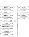
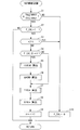
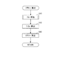
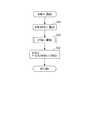
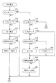
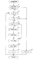
- 1 schematically shows a configuration of an internal combustion engine to which the present invention is applied. It is a block diagram which shows schematic structure of a temperature control apparatus. It is a main flow which shows the multi injection control processing by 1st Embodiment of this invention. It is a subroutine which shows calculation processing of target exhaust gas temperature. It is a subroutine which shows calculation processing of fuel injection time. It is a subroutine which shows calculation processing of a feedback amendment value of fuel injection time. It is a subroutine which shows the calculation processing of fuel injection quantity. It is a subroutine which shows calculation processing of the feedback amendment value of fuel injection quantity. It is a subroutine which shows a part of calculation process of real combustion time. It is a subroutine which shows the remainder of FIG.
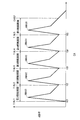
- FIG. 7 is a view showing an example of the maximum burning rate and the actual burning time in the first to fifth burning periods by multi injection. It is a main flow which shows the multi injection control processing by a 2nd embodiment of the present invention.
- the temperature control device 1 includes an ECU 2 for executing various controls including temperature control of the catalyst 10 described later, and an internal combustion engine shown in FIG. Apply to 3).
- the engine 3 is a diesel engine mounted on a vehicle (not shown), and has, for example, four cylinders 3a (only one is shown).
- a fuel injection valve (hereinafter referred to as "injector") 4 and a glow plug 11 are attached to the cylinder head 3b of the engine 3 so as to face the combustion chamber 3c.
- the valve opening time and the valve opening timing of the injector 4 are controlled by a drive signal from the ECU 2, whereby the fuel injection amount and the fuel injection timing are controlled.
- single injection is performed in which fuel is injected only once from the intake stroke to the compression stroke.
- multi-injection in which fuel is injected in a predetermined period from the compression stroke to the expansion stroke is performed. The injection of fuel by this multi-injection is performed by dividing it into multiple times (for example, five times).
- the glow plug 11 is for assisting ignition in the cylinder 3a.
- the glow plug 11 is connected to a battery (not shown) via an electrode, generates heat by the power supplied from the battery, and heats the inside of the cylinder 3a.
- the energization timing and the energization time of the glow plug 11 are controlled by a control signal from the ECU 2.
- An in-cylinder pressure sensor 21 is attached to the glow plug 11 (see FIG. 2).
- the in-cylinder pressure sensor 21 detects an amount of change in pressure (hereinafter referred to as “in-cylinder pressure change amount”) DP in the cylinder 3 a of the engine 3 and outputs a detection signal to the ECU 2.
- the ECU 2 calculates the in-cylinder pressure PCYL based on the in-cylinder pressure change amount DP.
- the engine 3 is provided with a turbocharger 7.
- the turbocharger 7 includes a compressor blade 7a provided in the intake passage 5, a turbine blade 7b provided in the exhaust passage 6 and integrally rotating with the compressor blade 7a, and a plurality of variable vanes 7c (only two are shown). , And a vane actuator 7d for driving the variable vane 7c.
- the compressor blade 7a integral therewith is also simultaneously rotated to perform a supercharging operation for supercharging the intake air.
- variable vane 7c is rotatably attached to the wall of a housing (not shown) that accommodates the turbine blade 7b, and is mechanically coupled to the vane actuator 7d.
- the degree of opening of the variable vane 7c is controlled by the ECU 2 via the vane actuator 7d.
- an air flow sensor 22, an intake temperature sensor 23, a throttle valve mechanism 8 and an intake pressure sensor 24 are provided in the intake passage 5 sequentially from the upstream side.
- the air flow sensor 22 and the intake air temperature sensor 23 are provided on the upstream side of the compressor blade 7a, and the intake air amount QA drawn into the engine 3 and the temperature in the intake passage 5 (hereinafter referred to as "intake air temperature”) TA It detects each and outputs the detection signal showing them to ECU2.
- the intake pressure sensor 24 detects a pressure in the intake passage 5 (hereinafter referred to as “intake pressure”) PB, and outputs a detection signal representing it to the ECU 2.
- the throttle valve mechanism 8 includes a throttle valve 8a and a TH actuator 8b for driving the same.
- the throttle valve 8 a is rotatably provided in the intake passage 5.
- the TH actuator 8 b is a combination of a motor and a reduction gear mechanism (neither is shown).
- the degree of opening of the throttle valve 8a is controlled by the ECU 2 via the TH actuator 8b, whereby the amount of intake air passing through the throttle valve 8a is controlled.
- the engine 3 is provided with an EGR device 9.
- the EGR device 9 serves to recirculate a part of the exhaust gas discharged to the exhaust passage 6 to the intake passage 5, and is located downstream of the compressor blade 7 a of the intake passage 5 and upstream of the turbine blade 7 b of the exhaust passage 6. It comprises an EGR passage 9a connected to the side, an EGR control valve 9b for opening and closing the EGR passage 9a, and the like.
- the EGR control valve 9 b is constituted by a solenoid valve whose lift changes continuously between the maximum value and the minimum value, and is electrically connected to the ECU 2.
- the ECU 2 changes the opening degree of the EGR passage 9a through the EGR control valve 9b to control the amount of recirculation of the exhaust gas that is recirculated through the EGR passage 9a (hereinafter referred to as "EGR amount").
- an EGR amount sensor 25 is provided in the EGR passage 9a.
- the EGR amount sensor 25 detects an EGR amount QEGR passing through the inside of the EGR passage 9a, and outputs a detection signal representing it to the ECU 2.
- the engine 3 is provided with a crank angle sensor 26.
- the crank angle sensor 26 is composed of a magnet rotor 26a and an MRE pickup 26b, and outputs a CRK signal and a TDC signal as pulse signals to the ECU 2 as the crankshaft 3d rotates.
- the CRK signal is output every predetermined crank angle (for example, 1 °).
- the ECU 2 calculates the number of revolutions NE of the engine 3 (hereinafter referred to as "engine revolution number") based on the CRK signal.
- the TDC signal is a signal indicating that the piston of each cylinder 3a is at a predetermined crank angle position slightly ahead of the top dead center at the start of the intake stroke, as in this embodiment, the engine 3 In the case of four cylinders, it is output at every crank angle of 180 °.
- the engine 3 is also provided with a cylinder discrimination sensor (not shown).
- the cylinder discrimination sensor outputs a cylinder discrimination signal, which is a pulse signal for discriminating the cylinder 3a, to the ECU 2.
- the ECU 2 calculates the crank angle CA for each cylinder 3a based on the cylinder discrimination signal, the CRK signal and the TDC signal. Specifically, the crank angle CA is reset to a value of 0 when the TDC signal is generated, and is incremented each time the CRK signal output every 1 ° is generated.
- a water temperature sensor 27 is provided on the main body of the engine 3.
- the water temperature sensor 27 detects a temperature (hereinafter referred to as “engine water temperature”) TW of cooling water circulating in a cylinder block (not shown) of the engine 3 and outputs a detection signal representing the temperature to the ECU 2.
- engine water temperature a temperature (hereinafter referred to as “engine water temperature”) TW of cooling water circulating in a cylinder block (not shown) of the engine 3 and outputs a detection signal representing the temperature to the ECU 2.
- the catalyst 10 described above is provided downstream of the turbine blade 7 b of the exhaust passage 6.
- the catalyst 10 is made of, for example, an oxidation catalyst, and is maintained in an active state when its temperature is higher than a predetermined activation temperature TCATREF, thereby oxidizing HC and CO in the exhaust gas flowing through the exhaust passage 6. , To purify the exhaust gas.
- the exhaust passage 6 is provided with a pre-catalyst exhaust gas temperature sensor 28 and a post-catalyst exhaust gas temperature sensor 29.
- the pre-catalyst exhaust gas temperature sensor 28 detects the temperature of the exhaust gas immediately upstream of the catalyst 10 (hereinafter referred to as “pre-catalyst exhaust gas temperature”) TCATB, and outputs a detection signal representing it to the ECU 2.
- the after-catalyst exhaust gas temperature sensor 29 detects the temperature of the exhaust gas immediately downstream of the catalyst 10 (hereinafter referred to as “after-catalyst exhaust gas temperature”) TCATA, and outputs a detection signal representing it to the ECU 2.
- a detection signal representing the depression amount (hereinafter referred to as “accelerator opening degree”) AP of the accelerator pedal (not shown) of the vehicle is injected from the accelerator pressure sensor 31 to the ECU 2 from the fuel pressure sensor 31.
- a detection signal representing a pressure of fuel (hereinafter referred to as “fuel pressure”) PF to be output is output.
- the ECU 2 is configured by a microcomputer including a CPU, a RAM, a ROM, an I / O interface (all not shown) and the like.
- the ECU 2 determines the operating state of the engine 3 according to the detection signals of the various sensors 21 to 31 described above, and the fuel injection control processing including the single injection and the multi injection described above according to the determined operating state. Run. Since this fuel injection control is performed for each cylinder 3a based on the cylinder discrimination signal, in the following, for convenience of explanation, the description will be made for one cylinder 3a.
- the fuel injection timing and the fuel injection amount by single injection are calculated by searching respective predetermined maps (neither of which are shown) according to the engine speed NE and the required torque PMCMD.
- the required torque PMCMD is calculated by searching a predetermined map (not shown) according to the engine speed NE and the accelerator opening AP.
- the ECU 2 includes a fuel supply unit, an operating condition detection unit, a fuel supply timing setting unit, a combustion start timing calculation unit, a target combustion start timing setting unit, a target exhaust gas temperature setting unit, a heat release rate calculation unit, It corresponds to the control means and the target maximum burning rate setting means.
- FIG. 3 is a flowchart showing multi-injection control processing for controlling multi-injection according to the first embodiment of the present invention.
- the present process is executed at a predetermined cycle shorter than the generation interval of the TDC signal.
- the fuel injection amounts to be injected by the first to fifth fuel injections are defined as the first to fifth fuel injection timings TINJ1 to TINJ5, respectively, for the first to fifth fuel injections by multi injection.
- the first to fifth fuel injection amounts QINJ1 to QINJ5, respectively, and the first to fifth fuel injection timings TINJ1 to TINJ5 and the first to fifth fuel injection amounts QINJ1 to QINJ5 are appropriately set to the fuel injection timing TINJn and the fuel injection It is called the quantity QINJn.
- step 1 it is determined whether the engine coolant temperature TW is less than a predetermined temperature TWREF and the intake air temperature TA is less than a predetermined temperature TAREF.
- the in-calculation flag F_CAL indicating that the fuel injection timing TINJn and fuel injection amount QINJn are being calculated by multi injection is "1". It is determined whether there is any (step 2).
- the in-calculation flag F_CAL is set to "1" in synchronization with the generation of the TDC signal.
- the injection order n is initialized to the value 1 in synchronization with the generation of this TDC signal.
- step 2 If the result of the determination in step 2 is YES, it is determined whether the injection order n is larger than the value 5 (step 3). When the result of this determination is NO, it is determined whether or not the under-calculation flag F_CAL has changed from "0" to "1" between the previous time and this time (step 4).
- FIG. 4 is a subroutine showing the process of calculating the target exhaust gas temperature TEMCMD.
- the temperature of the catalyst 10 hereinafter referred to as “the catalyst based on the pre-catalyst exhaust gas temperature TCATB and the post-catalyst exhaust gas temperature TCATA detected by the pre-catalyst exhaust gas temperature sensor 28 and the post-catalyst exhaust gas temperature sensor 29, respectively. Estimate temperature)).
- the catalyst temperature TCAT is calculated by a weighted average of the pre-catalyst exhaust gas temperature TCATB and the post-catalyst exhaust gas temperature TCATA.
- step 22 it is determined whether the calculated catalyst temperature TCAT is less than or equal to the activation temperature TCATREF (step 22).
- the determination result is YES and the catalyst temperature TCAT is lower than the activation temperature TCATREF, it is determined that the catalyst 10 is not in the activated state, and a value obtained by adding a first predetermined temperature TREF1 (for example, 20 degrees) to the catalyst temperature TCAT is a target
- a first predetermined temperature TREF1 for example, 20 degrees
- step 22 when the determination result in step 22 is NO and the catalyst temperature TCAT is higher than the activation temperature TCATREF, it is determined that the catalyst 10 is in the activated state, and the second predetermined temperature TREF2 (for example, 10 degrees) is determined from the activation temperature TCATREF. The value thus subtracted is set as the target exhaust gas temperature TEMCMD (step 24), and the present process is ended.
- the second predetermined temperature TREF2 for example, 10 degrees
- the target intake air amount QACMD is calculated by searching a predetermined map (not shown) according to the calculated target exhaust gas temperature TEMCMD.
- the TH actuator 8b By controlling the TH actuator 8b so that the detected intake air amount QA becomes the target intake air amount QACMD, feedback control is performed such that the intake air amount QA converges to the target intake air amount QACMD.
- the fuel injection timing TINJn for the injection order n is calculated (step 7), and the fuel injection amount QINJn is calculated (step 8). These calculation processes will be described later.
- the fuel injection timing TINJn is represented by a crank angle CA when fuel is injected.
- the injection order n is reset to the value 1 in synchronization with the generation of the TDC signal as in the case of the calculation under calculation flag F_CAL, the injection order n is set to 1 when the determination result in step 4 is YES. Accordingly, in steps 7 and 8, the first fuel injection timing TINJ1 and the first fuel injection amount QINJ1 are respectively calculated as the fuel injection timing TINJn and the fuel injection amount QINJn.
- step 9 the injection order n is incremented (step 9), and the present process is ended.
- the injection order n becomes 2 and the determination result of the above step 4 becomes NO. In this case, the above steps 5 and 6 are skipped.
- the second fuel injection timing TINJ2 and the second fuel injection amount QINJ2 are calculated as the fuel injection timing TINJn and the fuel injection amount QINJn, respectively. Thereafter, step 9 is executed to end the present process.
- the third to fifth fuel injection timings TINJ3 to TINJ5 and the third to fifth fuel injection amounts QINJ3 to QINJ5 are sequentially calculated by repeatedly executing the steps 7 and 8.
- the injection order n exceeds the value 5 by the execution of the step 9, so that the result of the determination of the step 3 becomes YES.
- the calculation in progress flag F_CAL is reset to "0" assuming that all calculations of the first to fifth fuel injection timings TINJ1 to TINJ5 and the first to fifth fuel injection amounts QINJ1 to QINJ5 are completed (step 10) End this process.
- the judgment result of the above-mentioned step 2 becomes NO, and in this case, the present processing ends.
- step 1 determines whether the engine coolant temperature TW is higher than the predetermined temperature TWREF, or when the intake air temperature TA is higher than the predetermined temperature TAREF.
- the engine water temperature TW and the intake air temperature TA are relatively high. Then, it is determined that the engine 3 is not in the cold operation state, the above-mentioned step 10 is executed, and the present process is ended.
- valve opening timing and the valve opening time of the injector 4 By controlling the valve opening timing and the valve opening time of the injector 4 based on the first to fifth fuel injection timings TINJ1 to TINJ5 and the first to fifth fuel injection amounts QINJ1 to QINJ5 calculated as described above , Five split injections by multi-injection are performed.
- FIG. 5 is a subroutine showing the process of calculating the fuel injection timing TINJn executed in step 7 described above.
- a basic value TINJBASEn of the fuel injection timing is calculated. Specifically, according to the engine rotational speed NE, the required torque PMCMD, the target intake air amount QACMD, and the target exhaust gas temperature TEMCMD calculated in the step 23 or 24, a predetermined first fuel injection timing map (not shown) Is calculated to calculate the first basic value TINJBASE1 of the fuel injection timing.
- the first basic value TINJBASE1 is set near the start of the expansion stroke in order to secure good ignition performance of the fuel, and more specifically, the target intake air amount QACMD is The smaller the number, the more advanced the angle is. Further, the first basic value TINJBASE1 is set more retarded in order to raise the temperature of the exhaust gas in a lower temperature state as the engine rotational speed NE is lower and the required torque PMCMD is lower.
- a first environmental correction value CENV1 is calculated (step 32).
- the first environmental correction value CENVn is calculated in accordance with the intake temperature TA, the intake pressure PB, the EGR amount QEGR, the fuel pressure PF, the properties of the fuel, the warm-up state of the engine 3, the energized state of the glow plug 11, etc.
- the correction values are calculated respectively by searching the maps (not shown) of and the correction values are added to each other.
- the property of the above fuel is calculated according to, for example, the actual combustion start timing of the fuel by single injection and the target combustion start timing, and the warm-up state of the engine 3 is the integrated value of the fuel injection amount from the start time It is determined in accordance with the wall surface temperature of the cylinder 3a estimated by the above equation.
- the first feedback correction value CFBI1 is calculated as described later (step 33). Then, the first fuel injection timing TINJ1 is calculated by adding the first environment correction value CENV1 and the first feedback correction value CFBI1 to the calculated first basic value TINJBASE1 (step 34), and the present process is ended.
- the second fuel injection timing TINJ2 is calculated in the steps 31 to 34. Specifically, in step 31, a predetermined second fuel injection timing map (not shown) is searched according to the engine rotational speed NE, the required torque PMCMD, the target intake air amount QACMD and the target exhaust gas temperature TEMCMD. A second basic value TINJBASE2 of the fuel injection timing is calculated. Next, a second environmental correction value CENV2 is calculated and a second feedback correction value CFBI2 is calculated according to the intake air temperature TA, the intake pressure PB, the EGR amount QEGR, the fuel pressure PF, and the properties of the fuel (step 32 and 33). Then, the second fuel injection timing TINJ2 is calculated by adding the second environment correction value CENV2 and the second feedback correction value CENV2 to the second basic value TINJBASE2 (step 34).
- the fuel injection is performed by searching predetermined third to fifth fuel injection timing maps (all not shown). Third to fifth basic values TINJBASE3 to TINJBASE5 of the period are respectively calculated (step 31).
- the third to fifth environment correction values CENV3 to CENV calculated in step 32 and the third to fifth feedback correction values CENV3 calculated in step 33 are added to the calculated third to fifth basic values TINJBASE3 to TINJBASE5.
- Third to fifth fuel injection timings TINJ3 to TINJ5 are calculated by adding CENV5 (step 34).
- FIG. 6 is a subroutine showing the process of calculating the feedback correction value CFBIn executed in step 33.
- step 41 the time when the fuel by the first fuel injection has actually started combustion is calculated as a first actual combustion time IG1.
- the calculation process will be described later.
- a first target combustion timing TIG1 to be a target of the first actual combustion timing IG1 is calculated by searching a predetermined map (not shown) according to the target exhaust gas temperature TEMCMD and the required torque PMCMD (step 42) ).
- a first feedback correction value CFBI1 for the fuel injection timing is calculated according to the calculated first actual combustion timing IG1 and the first target combustion timing TIG1 (step 43), and the present process is terminated.
- the calculation of the first feedback correction value CFBI1 is performed by, for example, PID feedback control so that the first actual combustion timing IG1 converges to the first target combustion timing TIG1.
- the second to fifth actual combustion timings IG2 to IG5 are calculated (step 41), the target exhaust gas temperature TEMCMD, etc. Accordingly, the second to fifth target combustion timings TIG2 to TIG5 are calculated by searching the respective predetermined maps (step 42). Then, second to fifth feedback correction values CFBI2 to CFBI5 are respectively calculated according to the second to fifth actual combustion timings IG2 to IG5 and the second to fifth target combustion timings TIG2 to TIG5 (step 43). .
- the first to fifth target combustion timings TIG1 to TIG5 continue combustion between the start of the first combustion period to be described later and the end of the fifth combustion period (see FIG. 12). Is set to be done. Further, the first to fifth target combustion timings TIG1 to TIG5 are set such that the lengths of the first to fifth combustion periods become longer as the target exhaust gas temperature TEMCMD becomes higher. This is because the temperature of the exhaust gas can be further raised by prolonging the entire combustion period in one combustion cycle as the first to fifth combustion periods are longer.
- FIG. 7 shows a subroutine of the process of calculating the fuel injection amount QINJn executed in step 8 described above.
- a predetermined first fuel injection amount map (not shown) is searched according to the engine rotational speed NE, the required torque PMCMD, the target exhaust gas temperature TEMCMD and the first fuel injection timing TINJ1.
- the first basic value QINJBASE1 of the fuel injection amount is calculated.
- the first feedback correction value CFBQ1 is calculated as described later (step 52). Then, the first fuel injection amount QINJ1 is calculated by adding the first feedback correction value CFBQ1 to the calculated first basic value QINJBASE1 (step 53), and the present process is ended.
- predetermined second to fifth fuel injection amounts The second to fifth basic values QINJBASE2 to QINJBASE5 of the fuel injection amount are calculated respectively by searching the map (all not shown) (step 51), and these second to fifth basic values QINJBASE2 to QINJBASE5 are calculated.
- the second to fifth fuel injection amounts QINJ2 to QINJ5 are calculated by adding the second to fifth feedback correction values CFBQ2 to CFBQ5 calculated at step 52 (step 53).
- the first to fifth basic values QINJBASE1 to QINJBASE5 are set to larger values as the target exhaust gas temperature TEMCMD is higher.
- FIG. 8 is a subroutine showing the process of calculating the feedback correction value CFBQn executed in step 52.
- the injection order n has a value of one. If the answer to this question is affirmative (YES), a target maximum combustion rate TVMAX is calculated by searching a predetermined map (not shown) according to the target exhaust gas temperature TEMCMD and the required torque PMCMD (step 62).
- the first maximum combustion rate VMAX1 in the first combustion period is read (step 63).
- the first maximum combustion velocity VMAX1 is calculated together with the actual combustion timing IGn in a calculation subroutine of the actual combustion timing IGN to be described later.
- the first feedback correction value CFBQ1 of the fuel injection amount is calculated according to the calculated target maximum combustion speed TVMAX and the first maximum combustion speed VMAX1 (step 64), and the present process is terminated.
- the calculation of the feedback correction value CFBQn is performed by, for example, PID feedback control so that the first maximum combustion speed VMAX1 converges to the target maximum combustion speed TVMAX.
- the second to fifth maximum combustion speeds VMAX2 to VMAX5 in the second to fifth combustion periods are read (step 63), and these second to fifth maximum values are read.
- Second to fifth feedback correction values CFBQ2 to CFBQ5 are calculated according to the combustion speeds VMAX2 to VMAX5 and the target maximum combustion speed TVMAX calculated at step 62 (step 64).
- FIGS. 9 to 11 are subroutines showing the process of calculating the actual combustion time IGn executed in the step 41.
- the present process is to calculate the actual combustion timing IGn in the first to fifth combustion periods together with the maximum combustion velocity VMAXn.
- these first to fifth combustion periods are the periods between the first and second fuel injection timings TINJ1 and TINJ2, and between the second and third fuel injection timings TINJ2 and TINJ3, respectively.
- Period, the period between the third and fourth fuel injection timings TINJ3, TINJ4, the period between the fourth and fifth fuel injection timings TINJ4, TINJ5, and the fifth fuel injection timing TINJ5 and the predetermined crank angle CAREF Defined as a period of
- step 71 it is judged if the first combustion period flag F_LINJ1 is "1".
- the first combustion period flag F_LINJ1 is set to "1" when within the first combustion period. If the determination result in this step 71 is YES, that is, within the first combustion period, it is determined whether or not the first combustion period flag F_LINJ1 has changed from “0” to “1” between the previous time and this time (step 72) ). The determination result is YES, and immediately after the start of the first fuel injection, the timing at which the heat release rate dQHR described later starts to increase is detected, and this timing is calculated as the first actual combustion timing IG1 (step 73) Thereafter, the process proceeds to step 74.
- step 73 is skipped, and the process proceeds to step 74.
- step 74 it is determined whether the heat release rate dQHR is equal to or higher than the previous value dQHRZ.
- the heat release rate dQHR is a heat release amount per unit crank angle, and is calculated according to the following equation (1) using the in-cylinder pressure PCYL detected by the in-cylinder pressure sensor 21.
- dQHR ( ⁇ ⁇ PCYL ⁇ 1000 ⁇ dV ⁇ + dPCYL ⁇ 1000 ⁇ V ⁇ ) / ( ⁇ 1)
- dQHR heat release rate
- ⁇ specific heat ratio of air-fuel mixture
- PCYL in-cylinder pressure
- dV ⁇ in-cylinder volume change rate
- dPCYL in-cylinder pressure change rate
- V ⁇ in-cylinder volume
- the specific heat ratio ⁇ is a predetermined value (eg, 1.34) It is set.
- the in-cylinder volume change rate dV ⁇ and the in-cylinder volume V ⁇ are both calculated based on the crank angle CA.
- step 74 When the determination result in step 74 is YES and dQHR ⁇ dQHRZ, the heat release amount dQHR at that time is set as the first maximum combustion speed VMAX1 (step 75), and the present process is ended.
- step 74 when the determination result of step 74 is NO and dQHR ⁇ dQHRZ, the present process ends.
- the first maximum burn rate VMAX1 is updated, so the first maximum burn rate VMAX1 is the maximum of the heat release rate dQHR in the first combustion period. It corresponds to the value (see FIG. 12).
- step 76 when the result of the determination in step 71 is NO and it is not the first combustion period, it is determined whether or not the second combustion period flag F_LINJ2 is "1" (step 76).
- the second combustion period flag F_LINJ2 is set to “1” when in the second combustion period. If the result of the determination in step 76 is YES, ie, within the second combustion period, it is determined whether or not the second combustion start flag F_INJ2 is "1" (step 77).
- the second combustion start flag F_INJ2 and third to fifth combustion start flags F_INJ3 to F_INJ5 described later indicate that combustion has started in each of the second to fifth combustion periods, in synchronization with the generation of the TDC signal. It is reset to "0".
- step 77 it is determined whether the heat release rate dQHR is less than or equal to the previous value dQHRZ (step 78). If the answer to this question is affirmative (YES), that is, if the heat release rate dQHR is decreasing, then the crank angle CA at that time is set as the second actual combustion time IG2 (step 79), and the process proceeds to step 80.
- step 78 when the result of the determination in step 78 is NO, and the heat release rate dQHR becomes higher than the previous value dQHRZ and starts to increase, it is determined that the fuel combustion by the second fuel injection is started, and the second combustion
- the start flag F_INJ2 is set to "1" (step 82), and the process proceeds to step 80.
- step 82 By the execution of this step 82, the determination result of the above-mentioned step 77 becomes YES, and in that case, the process directly proceeds to step 80.
- step 80 it is determined whether the heat release rate dQHR is equal to or higher than the previous value dQHRZ. If the answer to this question is affirmative (YES), the heat release rate dQHR at that time is set as the second maximum combustion speed VMAX2 (step 81), after which the present process is ended. On the other hand, when the result of the determination in step 80 is NO, the present process ends.
- the second actual combustion timing IG2 corresponds to the crank angle CA when the heat release rate dQHR exhibits the minimum value before the fuel starts to be burned in the second combustion period.
- the second maximum combustion rate VMAX2 is updated, so the second maximum combustion rate VMAX2 corresponds to the maximum value of the heat release rate dQHR in the second combustion period.
- step 83 it is determined whether the third combustion period flag F_LINJ3 is "1" (step 83).
- the third combustion period flag F_LINJ3 is set to "1" when in the third combustion period. If the result of the determination in step 83 is YES, that is, within the third combustion period, the same processing as in the steps 77 to 82 is performed in the steps 84 to 89 for the third combustion period, whereby the third actual combustion time IG3 And the third maximum burn rate VMAX3.
- step 84 it is judged if the third combustion start flag F_INJ3 is "1".
- the result of this determination is NO, it is determined that the combustion of fuel by the third fuel injection has not started, and it is determined whether the heat release rate dQHR is less than or equal to the previous value dQHRZ (step 85).
- the crank angle CA at that time is set as the third actual combustion timing IG3 (step 86), and while the processing proceeds to step 87, while the result of determination in step 85 is NO, the third fuel
- step 89 the process proceeds to step 87.
- step 89 the judgment result of the above-mentioned step 84 becomes YES, and in that case, it proceeds to step 87 as it is.
- step 87 it is determined whether the heat release rate dQHR is greater than or equal to the previous value dQHRZ.
- the result of this determination is YES, after setting the heat release rate dQHR at that time as the third maximum combustion speed VMAX3 (step 88), the present processing is ended, while when the result of determination in step 87 is NO, this processing is completed. Finish.
- the third fuel injection is performed and the third fuel injection is performed, so long as dQHR ⁇ dQHRZ is satisfied.
- the actual combustion time IG3 is updated, as shown in FIG. 12, the third actual combustion time IG3 is the time when the heat release rate dQHR shows the minimum value before the fuel starts burning in the third combustion period. It corresponds to the crank angle CA.
- the third maximum combustion speed VMAX3 is updated, so the third maximum combustion speed VMAX3 corresponds to the maximum value of the heat release rate dQHR in the third combustion period.
- step 90 it is determined whether the fourth combustion period flag F_LINJ4 is "1" (step 90).
- the fourth combustion period flag F_LINJ4 is set to “1” when in the fourth combustion period. If the result of the determination in step 90 is YES, that is, within the fourth combustion period, the same processing as in steps 77 to 82 and 84 to 89 is performed in steps 91 to 96 for the fourth combustion period. After the fourth actual combustion time IG4 and the fourth maximum combustion speed VMAX4 are calculated, the present process is ended.
- the fourth actual combustion timing IG4 and the fourth maximum combustion velocity VMAX4 are updated as in the case of the second and third combustion periods.
- the fourth actual combustion time IG4 corresponds to the crank angle CA when the heat release rate dQHR exhibits the minimum value in the fourth combustion period until the fuel starts to be burned, and the fourth maximum combustion speed VMAX4 This corresponds to the maximum value of the heat release rate dQHR in the four combustion periods.
- step 97 it is determined whether the fifth combustion period flag F_LINJ5 is "1" (step 97).
- the fifth combustion period flag F_LINJ5 is set to "1" when within the fifth combustion period.
- the fifth actual combustion timing IG5 is the period until the fuel starts to be burned in the fifth combustion period.
- the fifth maximum combustion speed VMAX5 corresponds to the maximum value of the heat release rate dQHR in the fifth combustion period.
- step 97 when the result of the determination in step 97 is NO and it is not in any of the first to fifth combustion periods, the present process ends.
- step 43 of FIG. 6 and step of FIG. 8 the actual combustion timing IGn and the maximum combustion velocity VMAXn converge to the target combustion timing TIGn and the target maximum combustion velocity TVMAX in each combustion period by calculating the first to fifth feedback correction values CFBI1 to CFBI5 and CFBQ1 to CFBQ5. To be controlled.
- the first to fifth actual combustion timings IG1 to IG5 are converged by feedback control so that the first to fifth target combustion timings TIG1 to TIG5 converge.
- the fifth fuel injection timings TINJ1 to TINJ5 are set.
- the first to fifth target combustion timings TIG1 to TIG5 are set in accordance with these parameters, using the target exhaust gas temperature TEMCMD and the required torque PMCMD as parameters. Therefore, the first to fifth fuel injection timings TINJ1 to TINJ5 can be controlled to an appropriate timing according to the above parameters.
- the catalyst 10 when the catalyst 10 is not in the activated state, the amount of unburned fuel discharged to the atmosphere can be reduced, and the catalyst can be rapidly activated while maintaining good exhaust gas characteristics.
- the temperature of the exhaust gas when the catalyst 10 is in the active state, the temperature of the exhaust gas can be maintained as low as possible while maintaining the temperature and purification capacity of the catalyst 10 appropriately, so that the unburned fuel can be discharged into the atmosphere. The quantity can be maximized and reduced, which keeps the exhaust gas properties good.
- the amount of fuel consumption can be reduced as much as unnecessary increase in the temperature of the exhaust gas can be avoided.
- first to fifth target combustion start timings TIG1 to TIG5 are set such that combustion is continuously performed between the first to fifth combustion periods. Therefore, combustion can be performed without interruption throughout the first to fifth combustion periods, and as a result, a more stable combustion state can be secured. As a result, the exhaust gas characteristics can be favorably maintained, and catalyst 10 can be rapidly Can be activated.
- the target exhaust gas temperature TEMCMD is set according to the calculated catalyst temperature TCAT, the target exhaust gas temperature TEMCMD can be set to be suitable for the temperature of the catalyst 10 at that time. Further, since the first to fifth target combustion timings are set such that the length of each combustion period becomes longer as the target exhaust gas temperature TEMCMD is higher, the temperature of the exhaust gas is appropriately controlled according to the temperature of the catalyst 10 As a result, the exhaust gas characteristics can be maintained better, and the catalyst can be rapidly activated.
- the first to fifth target combustion timings TIG1 to TIG5 Is set to the more retarded side, so that the exhaust gas characteristic can be kept better and the catalyst 10 can be rapidly activated.
- the first to fifth combustion timings IG1 to IG5 can be appropriately calculated. Therefore, since the first to fifth fuel injection timings TINJ1 to TINJ5 are set using these first to fifth combustion timings IG1 to IG5, the temperature of the exhaust gas can be appropriately controlled, and the exhaust gas characteristics can be maintained favorably.
- the catalyst 10 can be rapidly activated.
- the target maximum combustion speed TVMAX is set according to the target exhaust gas temperature TEMCMD (step 62), and feedback control is performed so that the first to fifth maximum combustion speeds VMAX1 to VMAX5 converge to the same target maximum combustion speed TVMAX. Is performed (step 64). Therefore, the fuel injection amount QINJn is controlled such that the first to fifth maximum combustion speeds VMAX1 to VMAX5 become equal to one another in the first to fifth combustion periods (steps 51 to 53). For this reason, the temperature of the exhaust gas can be more appropriately controlled, whereby the catalyst 10 can be rapidly activated while maintaining the exhaust gas characteristics better.
- the maximum value of the heat release rate dQHR calculated based on the detected in-cylinder pressure PCYL is used as the maximum combustion speed VMAXn, and the fuel injection amount QINJn is controlled accordingly, so the temperature of the exhaust gas can be appropriately controlled.
- the catalyst 10 can be rapidly activated while maintaining good exhaust gas characteristics.
- FIG. 13 shows a flowchart of multi-injection control processing according to the second embodiment of the present invention.
- the second embodiment differs from the first embodiment only in the method of calculating the fuel injection timing TINJn in step 200 of FIG. 13 and the fuel injection amount QINJn in step 201. That is, in the first embodiment described above, the fuel injection timing TINJn is calculated in a feedback manner so that the actual combustion timing IGn becomes the target combustion timing TIGn, whereas in the second embodiment, the fuel injection timing TINJn is fed. Calculate forward. In the first embodiment, the fuel injection amount QINJn is calculated in a feedback manner so that the maximum combustion speed VMAXn becomes the target maximum combustion speed TVMAX, while in the second embodiment, the fuel injection amount QINJn is feedforwarded. Calculated
- the first ignition delay period IGL1 is calculated.
- the first ignition delay period IGL1 is an ignition delay period associated with the first fuel injection, and includes engine rotational speed NE, intake air amount QA, intake air temperature TA, intake air pressure PB, EGR amount QEGR, fuel pressure PF, and fuel properties. The value is calculated according to the warm-up state of the engine 3, the energized state of the glow plug 11, and the like.
- the second ignition delay period IGL2 calculated from the second target combustion timing TIG2 according to the same parameters as those used for the calculation of the first ignition delay period IGL1
- the second fuel injection timing TINJ2 is calculated by subtraction.
- the third to fifth ignition delay periods IGL3 to IGL5 calculated by the same method as described above from the third to fifth target combustion timings TIG3 to TIG5
- the third to fifth combustion injection timings TINJ3 to TINJ5 are calculated by subtraction.
- the first engine fuel injection amount map (not shown) is searched according to the engine rotational speed NE, the required torque PMCMD, the target exhaust gas temperature TEMCMD, and the first fuel injection timing TINJ1.
- the fuel injection amount QINJ1 is calculated.
- predetermined second to fifth fuel injection amount maps (all not shown) are displayed.
- the second to fifth fuel injection amounts QINJ2 to QINJ5 are calculated by searching.
- the fuel injection timing TINJn and the fuel injection amount QINJn for five injections by multi-injection are set by feedforward control according to the operating state of the engine 3 such as the engine rotational speed NE.
- the fuel injection timing TINJn is set by feed forward control according to the operating state of the engine 3, the first to fifth actual combustion timings IG1 to IG5 The timing can be controlled appropriately according to the operating condition.
- the catalyst 10 when the catalyst 10 is not in the activated state, the amount of unburned fuel discharged to the atmosphere can be reduced, and the catalyst can be rapidly activated while maintaining good exhaust gas characteristics.
- the catalyst 10 when the catalyst 10 is in the active state, the temperature of the exhaust gas can be maintained as low as possible while maintaining the temperature and purification capacity of the catalyst 10 appropriately, so that the unburned fuel can be discharged into the atmosphere. The quantity can be maximized and reduced, which keeps the exhaust gas properties good.
- the amount of fuel consumption can be reduced as much as unnecessary increase in the temperature of the exhaust gas can be avoided.
- the fuel injection timing TINJn is set so that the actual combustion timing IGn converges to the target combustion timing TIGn.
- the heat release rate dQHR It may be performed according to the convergence state. In this case, for example, after the calculation of the first maximum combustion rate VMAX1 in the first combustion period, the timing at which the heat release rate dQHR falls below a predetermined value is calculated, and the second actual combustion timing IG2 coincides with this timing.
- the second fuel injection timing TINJ2 is set to. The same applies to the case where the third to fifth fuel injection timings TINJ3 to TINJ5 are set.
- the fuel injection timing TINJn is set using the heat release rate dQHR, the fuel injection timing TINJn is set to an appropriate timing according to the combustion state, and the combustion is continued over the entire first to fifth combustion periods. Can be done. Further, in such a setting method, the above-described predetermined value used to determine the convergence state of the heat release rate dQHR may be set to a smaller value as the target exhaust gas temperature is higher. As a result, when the target exhaust gas temperature is high, the first to fifth combustion periods are extended, respectively, and the amount of unburned fuel is suppressed, and the entire first to fifth combustion periods are reliably continued. And the temperature of the exhaust gas can be appropriately raised.
- the number of injections by multi injection for activating the catalyst 10 is five, but may be any number of two or more.
- the fuel injection timing TINJn is calculated by feedback control in the first embodiment and calculated by feed forward control in the second embodiment, the present invention is not limited to this, and calculation is performed by combining feedback control and feed forward control. You may
- the target exhaust gas temperature TMCMD is set according to the catalyst temperature TCAT estimated from the pre-catalyst exhaust gas temperature TCATB and the post-catalyst exhaust gas temperature TCATA, but without calculating the catalyst temperature TCAT It may be performed according to one or both of the temperatures TCATB and TCATA, or may be performed according to the catalyst temperature detected directly by a sensor provided on the catalyst 10.
- the actual combustion timing IGn is calculated based on the heat release rate dQHR, but the present invention is not limited thereto, and may be calculated using other appropriate parameters having correlation with the combustion state.
- the maximum value of the heat release rate dQHR is used as the maximum burning rate VMAXn, but the present invention is not limited to this, and another appropriate parameter having correlation with the burning rate may be used.
- the embodiment is an example in which the present invention is applied to a diesel engine mounted on a vehicle, but the present invention is not limited to this and may be applied to various engines such as gasoline engines other than diesel engines. Also, the present invention can be applied to engines other than those for vehicles, for example, marine propulsion engines such as outboard motors having crankshafts vertically arranged. In addition, it is possible to change suitably the composition of details within the limits of the meaning of the present invention.
- the catalyst temperature control device according to the present invention can be used for various internal combustion engines as it can maintain the exhaust gas characteristics well and can rapidly activate the catalyst.
Landscapes
- Engineering & Computer Science (AREA)
- Chemical & Material Sciences (AREA)
- Combustion & Propulsion (AREA)
- Mechanical Engineering (AREA)
- General Engineering & Computer Science (AREA)
- Exhaust Gas After Treatment (AREA)
- Electrical Control Of Air Or Fuel Supplied To Internal-Combustion Engine (AREA)
- Combined Controls Of Internal Combustion Engines (AREA)
Abstract
L'invention porte sur un dispositif de régulation de la température d'un catalyseur, les caractéristiques des gaz d'échappement pouvant être maintenues de manière satisfaisante, et le catalyseur pouvant être activé rapidement. Dans un dispositif de régulation de température (1) pour catalyseur (10), un carburant est distribué en plusieurs fois à un moteur à combustion interne (3). De plus, les états de fonctionnement (TCAT, PMCMD, NE, QA, TA, PB, QEGR, PF) du moteur à combustion interne (3) sont détectés, et une pluralité de temporisations d'alimentation en carburant (TINJ1 à TINJ5), au moyen desquelles le carburant est distribué en plusieurs fois par un moyen d'alimentation en carburant, sont établies en fonction de l'état de fonctionnement détecté du moteur à combustion interne (3).
Priority Applications (1)
| Application Number | Priority Date | Filing Date | Title |
|---|---|---|---|
| JP2011502678A JP5145455B2 (ja) | 2009-03-06 | 2010-01-19 | 触媒の温度制御装置 |
Applications Claiming Priority (2)
| Application Number | Priority Date | Filing Date | Title |
|---|---|---|---|
| JP2009-052929 | 2009-03-06 | ||
| JP2009052929 | 2009-03-06 |
Publications (1)
| Publication Number | Publication Date |
|---|---|
| WO2010100965A1 true WO2010100965A1 (fr) | 2010-09-10 |
Family
ID=42709529
Family Applications (1)
| Application Number | Title | Priority Date | Filing Date |
|---|---|---|---|
| PCT/JP2010/050564 Ceased WO2010100965A1 (fr) | 2009-03-06 | 2010-01-19 | Dispositif de régulation de température de catalyseur |
Country Status (2)
| Country | Link |
|---|---|
| JP (1) | JP5145455B2 (fr) |
| WO (1) | WO2010100965A1 (fr) |
Cited By (1)
| Publication number | Priority date | Publication date | Assignee | Title |
|---|---|---|---|---|
| GB2481364A (en) * | 2010-03-09 | 2011-12-28 | Gm Global Tech Operations Inc | A method for estimating the combustion of a quantity of fuel injected in a combustion chamber of a compression ignition internal combustion engine |
Citations (7)
| Publication number | Priority date | Publication date | Assignee | Title |
|---|---|---|---|---|
| JPH10252529A (ja) * | 1997-03-14 | 1998-09-22 | Mitsubishi Motors Corp | 燃料噴射時期制御装置 |
| JPH11173201A (ja) * | 1997-12-05 | 1999-06-29 | Isuzu Motors Ltd | エンジンにおけるパイロット燃料噴射制御方法及びその装置 |
| JP2002242744A (ja) * | 2001-02-14 | 2002-08-28 | Mazda Motor Corp | ディーゼルエンジンの燃料噴射装置 |
| JP2003184619A (ja) * | 2001-12-19 | 2003-07-03 | Toyota Motor Corp | ディーゼルエンジン |
| JP2004316610A (ja) * | 2003-04-18 | 2004-11-11 | Nissan Motor Co Ltd | エンジンの排気ガス浄化装置 |
| JP2005240757A (ja) * | 2004-02-27 | 2005-09-08 | Nissan Motor Co Ltd | 内燃機関の制御装置 |
| JP2007009864A (ja) * | 2005-07-04 | 2007-01-18 | Nissan Motor Co Ltd | 筒内直接噴射式火花点火内燃機関の制御装置 |
Family Cites Families (1)
| Publication number | Priority date | Publication date | Assignee | Title |
|---|---|---|---|---|
| JP4833924B2 (ja) * | 2007-06-28 | 2011-12-07 | 本田技研工業株式会社 | 内燃機関の制御装置 |
-
2010
- 2010-01-19 JP JP2011502678A patent/JP5145455B2/ja not_active Expired - Fee Related
- 2010-01-19 WO PCT/JP2010/050564 patent/WO2010100965A1/fr not_active Ceased
Patent Citations (7)
| Publication number | Priority date | Publication date | Assignee | Title |
|---|---|---|---|---|
| JPH10252529A (ja) * | 1997-03-14 | 1998-09-22 | Mitsubishi Motors Corp | 燃料噴射時期制御装置 |
| JPH11173201A (ja) * | 1997-12-05 | 1999-06-29 | Isuzu Motors Ltd | エンジンにおけるパイロット燃料噴射制御方法及びその装置 |
| JP2002242744A (ja) * | 2001-02-14 | 2002-08-28 | Mazda Motor Corp | ディーゼルエンジンの燃料噴射装置 |
| JP2003184619A (ja) * | 2001-12-19 | 2003-07-03 | Toyota Motor Corp | ディーゼルエンジン |
| JP2004316610A (ja) * | 2003-04-18 | 2004-11-11 | Nissan Motor Co Ltd | エンジンの排気ガス浄化装置 |
| JP2005240757A (ja) * | 2004-02-27 | 2005-09-08 | Nissan Motor Co Ltd | 内燃機関の制御装置 |
| JP2007009864A (ja) * | 2005-07-04 | 2007-01-18 | Nissan Motor Co Ltd | 筒内直接噴射式火花点火内燃機関の制御装置 |
Cited By (1)
| Publication number | Priority date | Publication date | Assignee | Title |
|---|---|---|---|---|
| GB2481364A (en) * | 2010-03-09 | 2011-12-28 | Gm Global Tech Operations Inc | A method for estimating the combustion of a quantity of fuel injected in a combustion chamber of a compression ignition internal combustion engine |
Also Published As
| Publication number | Publication date |
|---|---|
| JPWO2010100965A1 (ja) | 2012-09-06 |
| JP5145455B2 (ja) | 2013-02-20 |
Similar Documents
| Publication | Publication Date | Title |
|---|---|---|
| JP4818376B2 (ja) | 触媒の温度制御装置 | |
| EP1245815B1 (fr) | Moteur turbocompressé à allumage par étincelle et injection directe , méthode de commande, support de stockage lisible par ordinateur à cette fin. | |
| WO1998009062A1 (fr) | Unite de commande pour moteur thermique a allumage par injection dans le cylindre | |
| WO2002014665A1 (fr) | Moteur a combustion interne par compression | |
| JP4861915B2 (ja) | 内燃機関の制御装置 | |
| WO1998005856A1 (fr) | Dispositif de commande pour moteurs a combustion interne a injection dans les cylindres et allumage par bougie | |
| JP4848396B2 (ja) | 内燃機関の点火時期制御装置 | |
| JP2018091267A (ja) | 内燃機関の制御装置 | |
| US7900440B2 (en) | Exhaust emission control device and method for internal combustion engine and engine control unit | |
| JP4833924B2 (ja) | 内燃機関の制御装置 | |
| JP2005009324A (ja) | 圧縮着火式内燃機関の制御装置 | |
| JP5720479B2 (ja) | 内燃機関の制御装置 | |
| JP5145455B2 (ja) | 触媒の温度制御装置 | |
| JP5593132B2 (ja) | 内燃機関の制御装置 | |
| JP4518251B2 (ja) | 内燃機関の制御装置 | |
| JP4894815B2 (ja) | 車両用内燃機関の燃料圧力制御装置 | |
| JP5303349B2 (ja) | 内燃機関のegr制御装置 | |
| JP4615501B2 (ja) | 内燃機関の制御装置 | |
| JP2003161185A (ja) | ターボ過給機付筒内噴射エンジンの制御装置 | |
| JP5429148B2 (ja) | 予混合圧縮自己着火エンジン | |
| JP2002188550A (ja) | 直噴火花点火式エンジンの制御装置 | |
| JP4534968B2 (ja) | 内燃機関の制御装置 | |
| JP2009275679A (ja) | 内燃機関の吸気制御装置および内燃機関の自動適合装置 | |
| JP6599301B2 (ja) | 内燃機関の制御装置 | |
| JP4439467B2 (ja) | 内燃機関の制御装置 |
Legal Events
| Date | Code | Title | Description |
|---|---|---|---|
| 121 | Ep: the epo has been informed by wipo that ep was designated in this application |
Ref document number: 10748563 Country of ref document: EP Kind code of ref document: A1 |
|
| WWE | Wipo information: entry into national phase |
Ref document number: 2011502678 Country of ref document: JP |
|
| NENP | Non-entry into the national phase |
Ref country code: DE |
|
| 122 | Ep: pct application non-entry in european phase |
Ref document number: 10748563 Country of ref document: EP Kind code of ref document: A1 |