WO2010103680A1 - Procédé et système de purification de gaz de houille gazéifiée - Google Patents
Procédé et système de purification de gaz de houille gazéifiée Download PDFInfo
- Publication number
- WO2010103680A1 WO2010103680A1 PCT/JP2009/064231 JP2009064231W WO2010103680A1 WO 2010103680 A1 WO2010103680 A1 WO 2010103680A1 JP 2009064231 W JP2009064231 W JP 2009064231W WO 2010103680 A1 WO2010103680 A1 WO 2010103680A1
- Authority
- WO
- WIPO (PCT)
- Prior art keywords
- moisture
- gas
- raw material
- material gas
- carbon dioxide
- Prior art date
- Legal status (The legal status is an assumption and is not a legal conclusion. Google has not performed a legal analysis and makes no representation as to the accuracy of the status listed.)
- Ceased
Links
Images

Classifications
-
- C—CHEMISTRY; METALLURGY
- C10—PETROLEUM, GAS OR COKE INDUSTRIES; TECHNICAL GASES CONTAINING CARBON MONOXIDE; FUELS; LUBRICANTS; PEAT
- C10K—PURIFYING OR MODIFYING THE CHEMICAL COMPOSITION OF COMBUSTIBLE GASES CONTAINING CARBON MONOXIDE
- C10K1/00—Purifying combustible gases containing carbon monoxide
- C10K1/04—Purifying combustible gases containing carbon monoxide by cooling to condense non-gaseous materials
-
- B—PERFORMING OPERATIONS; TRANSPORTING
- B01—PHYSICAL OR CHEMICAL PROCESSES OR APPARATUS IN GENERAL
- B01D—SEPARATION
- B01D53/00—Separation of gases or vapours; Recovering vapours of volatile solvents from gases; Chemical or biological purification of waste gases, e.g. engine exhaust gases, smoke, fumes, flue gases, aerosols
- B01D53/002—Separation of gases or vapours; Recovering vapours of volatile solvents from gases; Chemical or biological purification of waste gases, e.g. engine exhaust gases, smoke, fumes, flue gases, aerosols by condensation
-
- B—PERFORMING OPERATIONS; TRANSPORTING
- B01—PHYSICAL OR CHEMICAL PROCESSES OR APPARATUS IN GENERAL
- B01D—SEPARATION
- B01D53/00—Separation of gases or vapours; Recovering vapours of volatile solvents from gases; Chemical or biological purification of waste gases, e.g. engine exhaust gases, smoke, fumes, flue gases, aerosols
- B01D53/26—Drying gases or vapours
- B01D53/261—Drying gases or vapours by adsorption
-
- B—PERFORMING OPERATIONS; TRANSPORTING
- B01—PHYSICAL OR CHEMICAL PROCESSES OR APPARATUS IN GENERAL
- B01D—SEPARATION
- B01D53/00—Separation of gases or vapours; Recovering vapours of volatile solvents from gases; Chemical or biological purification of waste gases, e.g. engine exhaust gases, smoke, fumes, flue gases, aerosols
- B01D53/34—Chemical or biological purification of waste gases
- B01D53/74—General processes for purification of waste gases; Apparatus or devices specially adapted therefor
- B01D53/75—Multi-step processes
-
- C—CHEMISTRY; METALLURGY
- C01—INORGANIC CHEMISTRY
- C01B—NON-METALLIC ELEMENTS; COMPOUNDS THEREOF; METALLOIDS OR COMPOUNDS THEREOF NOT COVERED BY SUBCLASS C01C
- C01B3/00—Hydrogen; Gaseous mixtures containing hydrogen; Separation of hydrogen from mixtures containing it; Purification of hydrogen; Reversible storage of hydrogen
- C01B3/50—Separation of hydrogen or hydrogen-containing gases from gaseous mixtures, e.g. purification
- C01B3/506—Separation of hydrogen or hydrogen-containing gases from gaseous mixtures, e.g. purification at low temperatures
-
- C—CHEMISTRY; METALLURGY
- C01—INORGANIC CHEMISTRY
- C01B—NON-METALLIC ELEMENTS; COMPOUNDS THEREOF; METALLOIDS OR COMPOUNDS THEREOF NOT COVERED BY SUBCLASS C01C
- C01B3/00—Hydrogen; Gaseous mixtures containing hydrogen; Separation of hydrogen from mixtures containing it; Purification of hydrogen; Reversible storage of hydrogen
- C01B3/50—Separation of hydrogen or hydrogen-containing gases from gaseous mixtures, e.g. purification
- C01B3/52—Separation of hydrogen or hydrogen-containing gases from gaseous mixtures, e.g. purification by contacting with liquids; Regeneration of used liquids
-
- C—CHEMISTRY; METALLURGY
- C01—INORGANIC CHEMISTRY
- C01B—NON-METALLIC ELEMENTS; COMPOUNDS THEREOF; METALLOIDS OR COMPOUNDS THEREOF NOT COVERED BY SUBCLASS C01C
- C01B3/00—Hydrogen; Gaseous mixtures containing hydrogen; Separation of hydrogen from mixtures containing it; Purification of hydrogen; Reversible storage of hydrogen
- C01B3/50—Separation of hydrogen or hydrogen-containing gases from gaseous mixtures, e.g. purification
- C01B3/56—Separation of hydrogen or hydrogen-containing gases from gaseous mixtures, e.g. purification by contacting with solids; Regeneration of used solids
-
- C—CHEMISTRY; METALLURGY
- C10—PETROLEUM, GAS OR COKE INDUSTRIES; TECHNICAL GASES CONTAINING CARBON MONOXIDE; FUELS; LUBRICANTS; PEAT
- C10K—PURIFYING OR MODIFYING THE CHEMICAL COMPOSITION OF COMBUSTIBLE GASES CONTAINING CARBON MONOXIDE
- C10K1/00—Purifying combustible gases containing carbon monoxide
- C10K1/002—Removal of contaminants
- C10K1/003—Removal of contaminants of acid contaminants, e.g. acid gas removal
- C10K1/004—Sulfur containing contaminants, e.g. hydrogen sulfide
-
- C—CHEMISTRY; METALLURGY
- C10—PETROLEUM, GAS OR COKE INDUSTRIES; TECHNICAL GASES CONTAINING CARBON MONOXIDE; FUELS; LUBRICANTS; PEAT
- C10K—PURIFYING OR MODIFYING THE CHEMICAL COMPOSITION OF COMBUSTIBLE GASES CONTAINING CARBON MONOXIDE
- C10K1/00—Purifying combustible gases containing carbon monoxide
- C10K1/002—Removal of contaminants
- C10K1/003—Removal of contaminants of acid contaminants, e.g. acid gas removal
- C10K1/005—Carbon dioxide
-
- C—CHEMISTRY; METALLURGY
- C10—PETROLEUM, GAS OR COKE INDUSTRIES; TECHNICAL GASES CONTAINING CARBON MONOXIDE; FUELS; LUBRICANTS; PEAT
- C10K—PURIFYING OR MODIFYING THE CHEMICAL COMPOSITION OF COMBUSTIBLE GASES CONTAINING CARBON MONOXIDE
- C10K1/00—Purifying combustible gases containing carbon monoxide
- C10K1/32—Purifying combustible gases containing carbon monoxide with selectively adsorptive solids, e.g. active carbon
-
- F—MECHANICAL ENGINEERING; LIGHTING; HEATING; WEAPONS; BLASTING
- F25—REFRIGERATION OR COOLING; COMBINED HEATING AND REFRIGERATION SYSTEMS; HEAT PUMP SYSTEMS; MANUFACTURE OR STORAGE OF ICE; LIQUEFACTION SOLIDIFICATION OF GASES
- F25J—LIQUEFACTION, SOLIDIFICATION OR SEPARATION OF GASES OR GASEOUS OR LIQUEFIED GASEOUS MIXTURES BY PRESSURE AND COLD TREATMENT OR BY BRINGING THEM INTO THE SUPERCRITICAL STATE
- F25J3/00—Processes or apparatus for separating the constituents of gaseous or liquefied gaseous mixtures involving the use of liquefaction or solidification
- F25J3/06—Processes or apparatus for separating the constituents of gaseous or liquefied gaseous mixtures involving the use of liquefaction or solidification by partial condensation
- F25J3/0605—Processes or apparatus for separating the constituents of gaseous or liquefied gaseous mixtures involving the use of liquefaction or solidification by partial condensation characterised by the feed stream
- F25J3/0625—H2/CO mixtures, i.e. synthesis gas; Water gas or shifted synthesis gas
-
- F—MECHANICAL ENGINEERING; LIGHTING; HEATING; WEAPONS; BLASTING
- F25—REFRIGERATION OR COOLING; COMBINED HEATING AND REFRIGERATION SYSTEMS; HEAT PUMP SYSTEMS; MANUFACTURE OR STORAGE OF ICE; LIQUEFACTION SOLIDIFICATION OF GASES
- F25J—LIQUEFACTION, SOLIDIFICATION OR SEPARATION OF GASES OR GASEOUS OR LIQUEFIED GASEOUS MIXTURES BY PRESSURE AND COLD TREATMENT OR BY BRINGING THEM INTO THE SUPERCRITICAL STATE
- F25J3/00—Processes or apparatus for separating the constituents of gaseous or liquefied gaseous mixtures involving the use of liquefaction or solidification
- F25J3/06—Processes or apparatus for separating the constituents of gaseous or liquefied gaseous mixtures involving the use of liquefaction or solidification by partial condensation
- F25J3/063—Processes or apparatus for separating the constituents of gaseous or liquefied gaseous mixtures involving the use of liquefaction or solidification by partial condensation characterised by the separated product stream
- F25J3/0655—Processes or apparatus for separating the constituents of gaseous or liquefied gaseous mixtures involving the use of liquefaction or solidification by partial condensation characterised by the separated product stream separation of hydrogen
-
- F—MECHANICAL ENGINEERING; LIGHTING; HEATING; WEAPONS; BLASTING
- F25—REFRIGERATION OR COOLING; COMBINED HEATING AND REFRIGERATION SYSTEMS; HEAT PUMP SYSTEMS; MANUFACTURE OR STORAGE OF ICE; LIQUEFACTION SOLIDIFICATION OF GASES
- F25J—LIQUEFACTION, SOLIDIFICATION OR SEPARATION OF GASES OR GASEOUS OR LIQUEFIED GASEOUS MIXTURES BY PRESSURE AND COLD TREATMENT OR BY BRINGING THEM INTO THE SUPERCRITICAL STATE
- F25J3/00—Processes or apparatus for separating the constituents of gaseous or liquefied gaseous mixtures involving the use of liquefaction or solidification
- F25J3/06—Processes or apparatus for separating the constituents of gaseous or liquefied gaseous mixtures involving the use of liquefaction or solidification by partial condensation
- F25J3/063—Processes or apparatus for separating the constituents of gaseous or liquefied gaseous mixtures involving the use of liquefaction or solidification by partial condensation characterised by the separated product stream
- F25J3/067—Processes or apparatus for separating the constituents of gaseous or liquefied gaseous mixtures involving the use of liquefaction or solidification by partial condensation characterised by the separated product stream separation of carbon dioxide
-
- B—PERFORMING OPERATIONS; TRANSPORTING
- B01—PHYSICAL OR CHEMICAL PROCESSES OR APPARATUS IN GENERAL
- B01D—SEPARATION
- B01D2253/00—Adsorbents used in seperation treatment of gases and vapours
- B01D2253/10—Inorganic adsorbents
- B01D2253/106—Silica or silicates
-
- B—PERFORMING OPERATIONS; TRANSPORTING
- B01—PHYSICAL OR CHEMICAL PROCESSES OR APPARATUS IN GENERAL
- B01D—SEPARATION
- B01D2253/00—Adsorbents used in seperation treatment of gases and vapours
- B01D2253/10—Inorganic adsorbents
- B01D2253/106—Silica or silicates
- B01D2253/108—Zeolites
-
- B—PERFORMING OPERATIONS; TRANSPORTING
- B01—PHYSICAL OR CHEMICAL PROCESSES OR APPARATUS IN GENERAL
- B01D—SEPARATION
- B01D2256/00—Main component in the product gas stream after treatment
- B01D2256/16—Hydrogen
-
- B—PERFORMING OPERATIONS; TRANSPORTING
- B01—PHYSICAL OR CHEMICAL PROCESSES OR APPARATUS IN GENERAL
- B01D—SEPARATION
- B01D2257/00—Components to be removed
- B01D2257/30—Sulfur compounds
- B01D2257/304—Hydrogen sulfide
-
- B—PERFORMING OPERATIONS; TRANSPORTING
- B01—PHYSICAL OR CHEMICAL PROCESSES OR APPARATUS IN GENERAL
- B01D—SEPARATION
- B01D2257/00—Components to be removed
- B01D2257/50—Carbon oxides
- B01D2257/504—Carbon dioxide
-
- B—PERFORMING OPERATIONS; TRANSPORTING
- B01—PHYSICAL OR CHEMICAL PROCESSES OR APPARATUS IN GENERAL
- B01D—SEPARATION
- B01D2257/00—Components to be removed
- B01D2257/80—Water
-
- B—PERFORMING OPERATIONS; TRANSPORTING
- B01—PHYSICAL OR CHEMICAL PROCESSES OR APPARATUS IN GENERAL
- B01D—SEPARATION
- B01D2259/00—Type of treatment
- B01D2259/40—Further details for adsorption processes and devices
- B01D2259/40083—Regeneration of adsorbents in processes other than pressure or temperature swing adsorption
- B01D2259/40086—Regeneration of adsorbents in processes other than pressure or temperature swing adsorption by using a purge gas
-
- B—PERFORMING OPERATIONS; TRANSPORTING
- B01—PHYSICAL OR CHEMICAL PROCESSES OR APPARATUS IN GENERAL
- B01D—SEPARATION
- B01D2259/00—Type of treatment
- B01D2259/40—Further details for adsorption processes and devices
- B01D2259/416—Further details for adsorption processes and devices involving cryogenic temperature treatment
-
- B—PERFORMING OPERATIONS; TRANSPORTING
- B01—PHYSICAL OR CHEMICAL PROCESSES OR APPARATUS IN GENERAL
- B01D—SEPARATION
- B01D53/00—Separation of gases or vapours; Recovering vapours of volatile solvents from gases; Chemical or biological purification of waste gases, e.g. engine exhaust gases, smoke, fumes, flue gases, aerosols
- B01D53/02—Separation of gases or vapours; Recovering vapours of volatile solvents from gases; Chemical or biological purification of waste gases, e.g. engine exhaust gases, smoke, fumes, flue gases, aerosols by adsorption, e.g. preparative gas chromatography
- B01D53/04—Separation of gases or vapours; Recovering vapours of volatile solvents from gases; Chemical or biological purification of waste gases, e.g. engine exhaust gases, smoke, fumes, flue gases, aerosols by adsorption, e.g. preparative gas chromatography with stationary adsorbents
- B01D53/047—Pressure swing adsorption
-
- B—PERFORMING OPERATIONS; TRANSPORTING
- B01—PHYSICAL OR CHEMICAL PROCESSES OR APPARATUS IN GENERAL
- B01D—SEPARATION
- B01D53/00—Separation of gases or vapours; Recovering vapours of volatile solvents from gases; Chemical or biological purification of waste gases, e.g. engine exhaust gases, smoke, fumes, flue gases, aerosols
- B01D53/34—Chemical or biological purification of waste gases
- B01D53/74—General processes for purification of waste gases; Apparatus or devices specially adapted therefor
- B01D53/77—Liquid phase processes
-
- C—CHEMISTRY; METALLURGY
- C01—INORGANIC CHEMISTRY
- C01B—NON-METALLIC ELEMENTS; COMPOUNDS THEREOF; METALLOIDS OR COMPOUNDS THEREOF NOT COVERED BY SUBCLASS C01C
- C01B2203/00—Integrated processes for the production of hydrogen or synthesis gas
- C01B2203/04—Integrated processes for the production of hydrogen or synthesis gas containing a purification step for the hydrogen or the synthesis gas
- C01B2203/0465—Composition of the impurity
- C01B2203/0475—Composition of the impurity the impurity being carbon dioxide
-
- C—CHEMISTRY; METALLURGY
- C01—INORGANIC CHEMISTRY
- C01B—NON-METALLIC ELEMENTS; COMPOUNDS THEREOF; METALLOIDS OR COMPOUNDS THEREOF NOT COVERED BY SUBCLASS C01C
- C01B2203/00—Integrated processes for the production of hydrogen or synthesis gas
- C01B2203/04—Integrated processes for the production of hydrogen or synthesis gas containing a purification step for the hydrogen or the synthesis gas
- C01B2203/0465—Composition of the impurity
- C01B2203/0485—Composition of the impurity the impurity being a sulfur compound
-
- C—CHEMISTRY; METALLURGY
- C01—INORGANIC CHEMISTRY
- C01B—NON-METALLIC ELEMENTS; COMPOUNDS THEREOF; METALLOIDS OR COMPOUNDS THEREOF NOT COVERED BY SUBCLASS C01C
- C01B2203/00—Integrated processes for the production of hydrogen or synthesis gas
- C01B2203/04—Integrated processes for the production of hydrogen or synthesis gas containing a purification step for the hydrogen or the synthesis gas
- C01B2203/0465—Composition of the impurity
- C01B2203/0495—Composition of the impurity the impurity being water
-
- C—CHEMISTRY; METALLURGY
- C10—PETROLEUM, GAS OR COKE INDUSTRIES; TECHNICAL GASES CONTAINING CARBON MONOXIDE; FUELS; LUBRICANTS; PEAT
- C10J—PRODUCTION OF PRODUCER GAS, WATER-GAS, SYNTHESIS GAS FROM SOLID CARBONACEOUS MATERIAL, OR MIXTURES CONTAINING THESE GASES; CARBURETTING AIR OR OTHER GASES
- C10J2300/00—Details of gasification processes
- C10J2300/09—Details of the feed, e.g. feeding of spent catalyst, inert gas or halogens
- C10J2300/0913—Carbonaceous raw material
- C10J2300/093—Coal
-
- F—MECHANICAL ENGINEERING; LIGHTING; HEATING; WEAPONS; BLASTING
- F25—REFRIGERATION OR COOLING; COMBINED HEATING AND REFRIGERATION SYSTEMS; HEAT PUMP SYSTEMS; MANUFACTURE OR STORAGE OF ICE; LIQUEFACTION SOLIDIFICATION OF GASES
- F25J—LIQUEFACTION, SOLIDIFICATION OR SEPARATION OF GASES OR GASEOUS OR LIQUEFIED GASEOUS MIXTURES BY PRESSURE AND COLD TREATMENT OR BY BRINGING THEM INTO THE SUPERCRITICAL STATE
- F25J2205/00—Processes or apparatus using other separation and/or other processing means
- F25J2205/40—Processes or apparatus using other separation and/or other processing means using hybrid system, i.e. combining cryogenic and non-cryogenic separation techniques
-
- F—MECHANICAL ENGINEERING; LIGHTING; HEATING; WEAPONS; BLASTING
- F25—REFRIGERATION OR COOLING; COMBINED HEATING AND REFRIGERATION SYSTEMS; HEAT PUMP SYSTEMS; MANUFACTURE OR STORAGE OF ICE; LIQUEFACTION SOLIDIFICATION OF GASES
- F25J—LIQUEFACTION, SOLIDIFICATION OR SEPARATION OF GASES OR GASEOUS OR LIQUEFIED GASEOUS MIXTURES BY PRESSURE AND COLD TREATMENT OR BY BRINGING THEM INTO THE SUPERCRITICAL STATE
- F25J2205/00—Processes or apparatus using other separation and/or other processing means
- F25J2205/50—Processes or apparatus using other separation and/or other processing means using absorption, i.e. with selective solvents or lean oil, heavier CnHm and including generally a regeneration step for the solvent or lean oil
-
- F—MECHANICAL ENGINEERING; LIGHTING; HEATING; WEAPONS; BLASTING
- F25—REFRIGERATION OR COOLING; COMBINED HEATING AND REFRIGERATION SYSTEMS; HEAT PUMP SYSTEMS; MANUFACTURE OR STORAGE OF ICE; LIQUEFACTION SOLIDIFICATION OF GASES
- F25J—LIQUEFACTION, SOLIDIFICATION OR SEPARATION OF GASES OR GASEOUS OR LIQUEFIED GASEOUS MIXTURES BY PRESSURE AND COLD TREATMENT OR BY BRINGING THEM INTO THE SUPERCRITICAL STATE
- F25J2205/00—Processes or apparatus using other separation and/or other processing means
- F25J2205/60—Processes or apparatus using other separation and/or other processing means using adsorption on solid adsorbents, e.g. by temperature-swing adsorption [TSA] at the hot or cold end
-
- F—MECHANICAL ENGINEERING; LIGHTING; HEATING; WEAPONS; BLASTING
- F25—REFRIGERATION OR COOLING; COMBINED HEATING AND REFRIGERATION SYSTEMS; HEAT PUMP SYSTEMS; MANUFACTURE OR STORAGE OF ICE; LIQUEFACTION SOLIDIFICATION OF GASES
- F25J—LIQUEFACTION, SOLIDIFICATION OR SEPARATION OF GASES OR GASEOUS OR LIQUEFIED GASEOUS MIXTURES BY PRESSURE AND COLD TREATMENT OR BY BRINGING THEM INTO THE SUPERCRITICAL STATE
- F25J2215/00—Processes characterised by the type or other details of the product stream
- F25J2215/04—Recovery of liquid products
-
- Y—GENERAL TAGGING OF NEW TECHNOLOGICAL DEVELOPMENTS; GENERAL TAGGING OF CROSS-SECTIONAL TECHNOLOGIES SPANNING OVER SEVERAL SECTIONS OF THE IPC; TECHNICAL SUBJECTS COVERED BY FORMER USPC CROSS-REFERENCE ART COLLECTIONS [XRACs] AND DIGESTS
- Y02—TECHNOLOGIES OR APPLICATIONS FOR MITIGATION OR ADAPTATION AGAINST CLIMATE CHANGE
- Y02C—CAPTURE, STORAGE, SEQUESTRATION OR DISPOSAL OF GREENHOUSE GASES [GHG]
- Y02C20/00—Capture or disposal of greenhouse gases
- Y02C20/40—Capture or disposal of greenhouse gases of CO2
-
- Y—GENERAL TAGGING OF NEW TECHNOLOGICAL DEVELOPMENTS; GENERAL TAGGING OF CROSS-SECTIONAL TECHNOLOGIES SPANNING OVER SEVERAL SECTIONS OF THE IPC; TECHNICAL SUBJECTS COVERED BY FORMER USPC CROSS-REFERENCE ART COLLECTIONS [XRACs] AND DIGESTS
- Y02—TECHNOLOGIES OR APPLICATIONS FOR MITIGATION OR ADAPTATION AGAINST CLIMATE CHANGE
- Y02P—CLIMATE CHANGE MITIGATION TECHNOLOGIES IN THE PRODUCTION OR PROCESSING OF GOODS
- Y02P20/00—Technologies relating to chemical industry
- Y02P20/151—Reduction of greenhouse gas [GHG] emissions, e.g. CO2
Definitions
- the present invention relates to a raw material gas obtained by gasifying coal, that is, a method and system for purifying coal gasification gas.
- the source gas is mainly composed of hydrogen and carbon dioxide, contains a trace amount of water, and may contain a trace amount of hydrogen sulfide depending on the source material.
- the raw material gas includes not only gas obtained by gasifying coal but also gas obtained by subjecting fossil resources such as natural gas and petroleum to a steam reforming reaction.
- Patent Document 1 a gas containing hydrogen and carbon dioxide is separated into a first product stream and a first off-gas stream in which carbon dioxide is 80% or more by a carbon dioxide scrubber which is a first separator.
- the first off-gas stream is separated into a second product stream with a hydrogen content of 99% or more and a second off-gas stream by a hydrogen pressure swing adsorption (H 2 -PSA) device as a second separator.
- H 2 -PSA hydrogen pressure swing adsorption
- the main components of the raw material gas obtained by gasifying coal are hydrogen and carbon dioxide
- carbon dioxide is recovered from the raw material gas in a liquid state simultaneously with hydrogen using the gas separation method described in Patent Document 1. If it is possible, the utility value is high as a carbon dioxide recovery storage (CCS) technique.
- CCS carbon dioxide recovery storage
- the coal gasification gas contains moisture
- this separation method is adopted for the coal gasification gas, the moisture is condensed and solidified prior to the carbon dioxide liquefaction by the carbon dioxide liquefaction device. End up.
- moisture condenses in the liquefier carbon dioxide dissolves in the water, which causes a problem that the surface of the liquefier is corroded.
- the moisture is solidified, there is a problem that the surface of the liquefying device is damaged or the device and piping are blocked.
- the carbon dioxide scrubber which is the first separator
- the separation is performed using the absorption liquid
- the first separator is connected to the second separator so that the fluid directly communicates
- the gas Also, there is a problem that a small amount of absorption liquid accompanying the gas enters the pores of the adsorbent of the H 2 -PSA apparatus as the second separator, thereby reducing the purification performance of the apparatus.
- an object of the present invention is to provide a coal gasification gas purification method and system capable of recovering carbon dioxide in a liquid state simultaneously with hydrogen from gas obtained by gasifying coal. .
- the present invention is a system for purifying a raw material gas obtained by gasifying coal, the water removing device for removing water in the raw material gas, and the water removing device And a liquefying device for extracting carbon dioxide in a liquid state from the raw material gas from which moisture has been removed.
- the moisture removing device is filled with a molecular sieve.
- This purification system can further include a pressure swing adsorption device for extracting hydrogen from the raw material gas from which carbon dioxide has been removed by the liquefaction device.
- a gas pipe for supplying a part of hydrogen taken out by the pressure swing adsorption device as a regeneration gas to the moisture removal device can be further provided, and off-gas generated in the pressure swing adsorption device can be removed by the moisture removal.
- a gas pipe for supplying the apparatus as a regeneration gas may be further provided.
- a gas pipe for supplying a part of the raw material gas from which carbon dioxide has been removed by the liquefaction device as a regeneration gas to the moisture removing device can be further provided, and off gas generated by the moisture removing device can be provided.
- a gas pipe for supplying the moisture removing device as a regeneration gas can be further provided.
- a gas pipe for supplying a part of the raw material gas from which moisture has been removed by the moisture removing device to the moisture removing device as a regeneration gas may be further provided.
- the hydrogen sulfide removing device is preferably a physical absorbing device that removes hydrogen sulfide by a physical absorption method.
- a solvent removal device for removing the solvent from the raw material gas from which hydrogen sulfide has been removed by the physical absorption device may be further provided on the upstream side of the moisture removal device.
- the solvent removal device is preferably filled with silica gel.
- Another aspect of the present invention is a method for refining a raw material gas obtained by gasifying coal, a water removal step for removing water in the raw material gas, and a raw material gas from which water has been removed in the water removal step. And a carbon dioxide separation step of taking out carbon dioxide in a liquid state.
- This purification method may further include a hydrogen separation step in which hydrogen is extracted from the source gas from which carbon dioxide has been removed in the carbon dioxide separation step by a pressure swing adsorption method.
- the method may further include the step of regenerating the molecular sieve that has adsorbed the moisture using a part of the hydrogen extracted by the pressure swing adsorption method, and the off-gas generated by the pressure swing adsorption method may be used to regenerate the moisture. It is also possible to further include a step of regenerating the molecular sieve adsorbing the.
- the method may further include a step of regenerating the molecular sieve adsorbing the moisture using a part of the raw material gas from which carbon dioxide has been removed in the carbon dioxide separation step. Further, the method may further include a step of regenerating the molecular sieve that has adsorbed the moisture using a part of the raw material gas from which the moisture has been removed in the moisture removal step, and uses an off-gas generated in the moisture removal step. And regenerating the molecular sieve adsorbing the moisture.
- it may further include a hydrogen sulfide separation step of removing hydrogen sulfide in the raw material gas before removing water from the raw material gas in the moisture removing step.
- a hydrogen sulfide separation step it is preferable that hydrogen sulfide is removed by a physical absorption method.
- the method may further include a solvent removal step of removing the solvent from the raw material gas from which hydrogen sulfide has been removed in the hydrogen sulfide separation step, before removing moisture in the moisture removal step.
- the solvent can be removed using silica gel.
- the gas obtained by gasifying coal contains moisture
- carbon dioxide can be recovered in a liquid state simultaneously with hydrogen.
- hydrogen and carbon dioxide are the main components
- the raw material gas containing a trace amount of moisture is not limited to the gas obtained by gasifying coal, and steam reforming of fossil resources such as natural gas and petroleum. The same effect can be obtained with the gas obtained by the reaction.
- the refining system of the present embodiment includes a physical absorption device 10 that removes hydrogen sulfide from a raw material gas obtained by gasifying coal, a water removal device 20 that removes water in the raw material gas, and a raw material. It mainly comprises a liquefaction device 30 that extracts carbon dioxide in the gas in a liquid state and a pressure swing adsorption (PSA) device 40 that extracts hydrogen in the raw material gas.
- a physical absorption device 10 that removes hydrogen sulfide from a raw material gas obtained by gasifying coal
- a water removal device 20 that removes water in the raw material gas
- a raw material mainly comprises a liquefaction device 30 that extracts carbon dioxide in the gas in a liquid state and a pressure swing adsorption (PSA) device 40 that extracts hydrogen in the raw material gas.
- PSA pressure swing adsorption
- the physical absorption device 10 is a device that removes acidic gas by a physical absorption method, and preferably employs, for example, a Selexol process. As shown in FIG. 1, the physical absorption device 10 includes an absorber 11 that absorbs and removes hydrogen sulfide in a source gas, a stripper 14 that regenerates an absorbing solution that has absorbed hydrogen sulfide, and a sulfide that is separated from the absorbing solution by the stripper 14. It is mainly composed of a knockout drum 17 that removes mist accompanying hydrogen gas.
- the absorber 11 includes equipment for cooling the source gas to a room temperature or lower under a high pressure condition of, for example, 6 MPa (about 60 atm) or lower.
- a pipe 12 for sending the raw material gas from which hydrogen sulfide has been removed to the moisture removing device 10 is provided at the top of the absorber 11, and a pipe for sending the absorbing liquid that has absorbed hydrogen sulfide to the stripper 14 at the bottom of the absorber 11. 13 is provided.
- the stripper 14 is an absorption liquid regeneration tower that heats the absorption liquid that has absorbed hydrogen sulfide and desorbs hydrogen sulfide from the absorption liquid.
- a pipe 15 for sending a processing gas containing hydrogen sulfide to the knockout drum 17 is provided, and at the bottom of the stripper 14, a pipe 16 for sending the regenerated absorbent to the absorber 11 is provided.
- the knockout drum 17 is a device that removes the absorbing liquid accompanying the hydrogen sulfide gas discharged from the stripper 14.
- the demister 18 is disposed at the top of each of the absorber 11, stripper 14, and knockout drum 17.
- the demister 18 is a filter that removes mist accompanying the gas, and it is preferable to use a porous mesh.
- a heat exchanger 19 is installed in each of the pipe 15 for sending the processing gas from the stripper 14 to the knockout drum 17 and the pipe 16 for sending the regenerated absorbent from the stripper 14 to the absorber 11.
- the moisture removing device 20 includes a packed tower filled with molecular sieves for absorbing and removing moisture contained in the raw material gas.
- molecular sieve those capable of sufficiently exhibiting the moisture adsorption ability even under conditions where the pressure of the raw material gas is from atmospheric pressure to 60 atm and the temperature is from room temperature to 60 ° C. are preferable.
- A-type zeolite can be used.
- the packed tower is provided with a switching valve 22 in the source gas pipe 12 so that a plurality of towers are installed in parallel and the source gas can be alternately processed.
- a switching valve 24 is also provided in the pipe 21 for feeding the raw material gas from which moisture has been removed from the moisture removing device 20 to the liquefying device 30.
- a solvent removal device 23 for removing the absorbing liquid accompanying the raw material gas is disposed in the raw material gas pipe 12 between the physical absorption device 10 and the water removing device 20.
- the solvent removing device 23 is preferably filled with silica gel having the ability to adsorb the solvent used in the absorbing liquid.
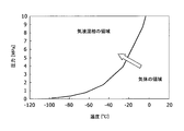
- the liquefying device 30 is a device that compresses and cools the raw material gas, and gas-liquid separates the desired components using the difference in temperature at which each component in the gas condenses. Since the liquefying device 30 separates carbon dioxide in the raw material gas in a liquid state, as shown in the graph of the state diagram of the mixed substance of hydrogen and carbon dioxide in FIG. Gas-liquid separation is possible by performing both compression or cooling of the source gas and compression cooling so that the mixed substance on the left side of the condensation line changes to a region where the mixed substance exists in the gas-liquid mixed phase. .
- the liquefying device 30 is provided with a pipe 31 for sending the raw material gas from which carbon dioxide has been removed to the PSA device 40.
- the PSA apparatus 40 includes a packed tower filled with an adsorbent for absorbing and removing carbon dioxide still contained in the raw material gas.
- the packed tower is equipped with equipment capable of increasing the pressure in the tower to a predetermined adsorption pressure during adsorption and depressurizing to a desorption pressure during regeneration.
- a preferable adsorption pressure is 10 atm or more, and a preferable desorption pressure is atmospheric pressure or less.
- the packed tower is provided with a switching valve 42 in the source gas pipe 31 so that a plurality of towers are installed in parallel and the source gas can be processed alternately.
- a switching valve 44 is also provided in the piping 41 that discharges purified hydrogen gas from the PSA device 40.
- a pipe 45 for sending a part of the purified hydrogen gas to the moisture removing device 20 is installed in the hydrogen gas pipe 41 via a valve 46.
- the raw material gas 1 obtained by gasifying coal is introduced into the bottom of the absorber 11 of the physical absorption device 10.
- the main components of the source gas 1 are hydrogen and carbon dioxide, but also include hydrogen sulfide and water.
- the hydrogen sulfide in the raw material gas 1 can be absorbed and removed by spraying the absorbing liquid from the tower top. Since physical absorption is normally performed under low temperature and pressure, the pressure of the raw material gas 1 discharged from the absorber 11 is often about 30 atm or higher and the temperature is 40 ° C. or lower in many cases.
- the raw material gas from which hydrogen sulfide has been removed is sent to the solvent removing device 23 via the pipe 12 from the top of the tower after the mist is removed by the demister 18a.
- the absorbing liquid that has absorbed hydrogen sulfide is sent to the stripper 14 via the pipe 13.
- the stripper 14 can separate the hydrogen sulfide from the absorbing liquid by heating the absorbing liquid that has absorbed the hydrogen sulfide.
- the separated hydrogen sulfide gas 2 is discharged from the pipe 15 at the top of the tower after the mist is removed by the demister 18b.
- the hydrogen sulfide gas 2 is cooled by the heat exchanger 19 c and then introduced into the knockout drum 17 to condense and remove the absorbing liquid accompanying the gas. And after removing mist with the demister 18b further, in order to collect
- the absorption liquid regenerated by the stripper 14 is returned to the absorber 11 through the piping 16 at the bottom, and used again for absorbing and removing hydrogen sulfide.
- a part of the regenerated absorbent discharged from the stripper 14 via the pipe 16 is reheated by the heat exchanger 19b and then returned to the stripper 14.
- the solvent removal device 23 adsorbs and removes the absorption liquid accompanying the raw material gas by the solvent adsorption silica gel filled therein. Thereby, it can prevent that the absorption liquid used with the physical absorption apparatus 10 has a bad influence on the downstream process.
- the raw material gas from which the absorbing liquid has been removed by the solvent removing device 23 is introduced into the moisture removing device 20.
- the switching valves 22 and 24 are operated to introduce the raw material gas into one packed tower. Then, moisture is adsorbed and removed from the raw material gas by a molecular sieve for moisture adsorption in the packed tower. Thereby, the water
- the moisture removal apparatus 20 can continuously perform the moisture removal treatment of the source gas.
- the moisture removing device 20 is installed in a plurality of stages in series, uses an adsorbent that is inexpensive, such as silica gel, and has a low moisture adsorbing capacity as the upstream stage, and is expensive and contains moisture such as molecular sieve in the downstream.
- an adsorbent having a high adsorption capacity the amount of molecular sieve filled can be reduced as compared with the case where the molecular sieve is used in a single stage, and the apparatus cost can be reduced.
- the raw material gas from which moisture has been removed is introduced into the liquefaction apparatus 30 via the pipe 21.
- the raw material gas is compressed and cooled, whereby carbon dioxide in the raw material gas can be liquefied and separated from the raw material gas. Since the raw material gas does not contain moisture, other components are not liquefied or solidified while being compressed and cooled until the carbon dioxide is liquefied, and the liquefying device 30 is prevented from being corroded, damaged or blocked. be able to. Further, the obtained carbon dioxide 3 can be sequestered as it is in the ground or on the sea floor without being released to the atmosphere if the purity is about 96% or more.
- the raw material gas that has undergone the liquefaction separation process of carbon dioxide in the liquefaction device 30 is introduced into the PSA device 40 via the pipe 31.
- the pressure of the raw material gas in the pipe 31 is 10 atm.
- the source gas discharged from the liquefaction apparatus 30 is mainly composed of hydrogen but also contains a small amount of carbon dioxide.
- the switching valves 42 and 44 are operated to introduce the raw material gas into one packed tower whose pressure has been increased to a predetermined pressure, and a small amount of carbon dioxide is adsorbed and removed by the adsorbent in the packed tower. .
- the other packed tower While the adsorption removal is performed in one packed tower, the other packed tower is supplied with nitrogen gas 6 under atmospheric pressure to regenerate the adsorbent that has adsorbed carbon dioxide.
- the nitrogen gas used for this regeneration process is discharged as off-gas 7.
- the other packed tower When the adsorbent of one packed tower has sufficiently adsorbed carbon dioxide, the other packed tower is pressurized to a predetermined pressure and the switching valves 42 and 44 are operated to introduce the raw material gas into the other packed tower.
- One packed tower reduces the pressure to atmospheric pressure, supplies nitrogen gas 6, releases the adsorbed carbon dioxide, and regenerates the adsorbent. In this way, highly purified hydrogen gas 4 can be continuously obtained by alternately repeating adsorption and release of carbon dioxide in two packed towers.
- the purified hydrogen gas 4 can be used for regenerating the molecular sieve of the moisture removing device 20.
- the valve 46 is opened and a part of the hydrogen gas 4 is supplied to the moisture removing device 20 through the pipe 45.
- the hydrogen gas 4 used for regeneration is preferably set to a temperature of 200 ° C. to 300 ° C.
- the moisture contained in the raw material gas 1 obtained by gasifying coal enters the liquefaction device 30 by disposing the moisture removal device 20 provided with the molecular sieve between the physical absorption device 10 and the liquefaction device 30. Can be prevented. Thereby, it is possible to prevent water from condensing in the liquefying device 30 and corroding the inside of the device, or water solidifying and damaging or blocking the device.
- a part of the hydrogen gas 4 purified by the PSA device 40 is used for regeneration of the molecular sieve of the moisture removing device 20.
- the present invention is not limited to this, and is generated by the PSA device 40.
- the off gas 7, the off gas 5 generated in the moisture removing device 20, a part of 21 flowing into the liquefaction device, and a part of 31 flowing into the PSA device can also be used.
- the off gas 7 generated in the PSA device 40 contains carbon dioxide, the carbon dioxide can be recovered in a liquid state by being supplied to the liquefying device 30. Since both the absorber 11 and the liquefying device 30 of the physical absorption device 10 operate at a low temperature, the same refrigeration source (not shown) can be used.
- the physical absorption device 10 is provided to remove hydrogen sulfide in the raw material gas 1.
- the sulfur content is small and the hydrogen sulfide is removed.
- the raw material gas 1 can be introduced into the moisture removing device 20 without installing the physical absorption device 10.
- a moisture removal device was designed to remove moisture from less than 1 ppm from a gas consisting of about 50% hydrogen, about 50% carbon dioxide, about 50% carbon dioxide, and 0.1% water at about 600,000 Nm 3 / h.
- the packed tower is composed of three units, and one unit is regenerated while two units are adsorbed.
- the adsorption / desorption is switched approximately every 12 hours. After adsorption with a source gas at 40 ° C. for 12 hours, a desorption operation is performed with a regeneration gas at about 280 ° C. for about 3.5 hours. Thereafter, the cooling operation is performed for about 2.5 hours with the regeneration gas at 40 ° C., and the operation is shifted to the adsorption operation again.
Landscapes
- Chemical & Material Sciences (AREA)
- Engineering & Computer Science (AREA)
- Combustion & Propulsion (AREA)
- Organic Chemistry (AREA)
- Chemical Kinetics & Catalysis (AREA)
- Oil, Petroleum & Natural Gas (AREA)
- General Chemical & Material Sciences (AREA)
- Thermal Sciences (AREA)
- Physics & Mathematics (AREA)
- Mechanical Engineering (AREA)
- Inorganic Chemistry (AREA)
- General Engineering & Computer Science (AREA)
- Analytical Chemistry (AREA)
- Environmental & Geological Engineering (AREA)
- Health & Medical Sciences (AREA)
- Biomedical Technology (AREA)
- Industrial Gases (AREA)
- Separation Of Gases By Adsorption (AREA)
- Separation By Low-Temperature Treatments (AREA)
- Drying Of Gases (AREA)
- Hydrogen, Water And Hydrids (AREA)
- Carbon And Carbon Compounds (AREA)
Abstract
L'invention concerne un procédé et un appareil de purification de gaz de houille gazéifiée, dans lequel du dioxyde de carbone peut être récupéré sous forme liquide simultanément à de l'hydrogène à partir du gaz de houille gazéifiée. Lorsque de gaz de matière première (1) obtenu par gazéification de la houille est purifié, la teneur en eau dudit gaz (1) est d'abord éliminée au moyen d'un tamis moléculaire de dispositif d'élimination de teneur en eau (20). Puis, le dioxyde de carbone (3) sous forme liquide est éliminé du gaz de matière première dont la teneur en eau a été éliminée au moyen d'un dispositif de liquéfaction (30). Enfin, l'hydrogène gazeux hautement purifié (4) est récupéré du gaz de matière première dont le dioxyde de carbone a été éliminé au moyen d'un dispositif d'adsorption modulée en pression (40).
Applications Claiming Priority (2)
| Application Number | Priority Date | Filing Date | Title |
|---|---|---|---|
| JP2009-057477 | 2009-03-11 | ||
| JP2009057477A JP2010209235A (ja) | 2009-03-11 | 2009-03-11 | 石炭ガス化ガスの精製方法およびシステム |
Publications (1)
| Publication Number | Publication Date |
|---|---|
| WO2010103680A1 true WO2010103680A1 (fr) | 2010-09-16 |
Family
ID=42727981
Family Applications (1)
| Application Number | Title | Priority Date | Filing Date |
|---|---|---|---|
| PCT/JP2009/064231 Ceased WO2010103680A1 (fr) | 2009-03-11 | 2009-08-12 | Procédé et système de purification de gaz de houille gazéifiée |
Country Status (2)
| Country | Link |
|---|---|
| JP (1) | JP2010209235A (fr) |
| WO (1) | WO2010103680A1 (fr) |
Cited By (3)
| Publication number | Priority date | Publication date | Assignee | Title |
|---|---|---|---|---|
| EP2476477A1 (fr) * | 2011-01-13 | 2012-07-18 | Alstom Technology Ltd | Procédé de séchage d'un flux de gaz humide riche en CO2 pour un procédé d'oxy-combustion |
| EP2481471A1 (fr) * | 2011-02-01 | 2012-08-01 | Alstom Technology Ltd | Appareil et système pour la réduction de NOx dans les gaz combustibles humides |
| CN107725018A (zh) * | 2017-09-20 | 2018-02-23 | 中国石油天然气股份有限公司 | 用于火驱尾气的处理系统 |
Families Citing this family (2)
| Publication number | Priority date | Publication date | Assignee | Title |
|---|---|---|---|---|
| JP2023027674A (ja) * | 2021-08-17 | 2023-03-02 | 国立研究開発法人産業技術総合研究所 | 高圧水素供給システム及びその方法 |
| JP7653951B2 (ja) * | 2022-07-13 | 2025-03-31 | 三菱重工業株式会社 | 燃料供給装置及び燃焼設備 |
Citations (3)
| Publication number | Priority date | Publication date | Assignee | Title |
|---|---|---|---|---|
| JP2003081605A (ja) * | 2001-09-05 | 2003-03-19 | Kawasaki Heavy Ind Ltd | 液化co2回収を伴う水素製造方法 |
| JP2004519538A (ja) * | 2000-12-19 | 2004-07-02 | フルー・コーポレイシヨン | 改良された水素および二酸化炭素の同時生成 |
| JP2008239359A (ja) * | 2007-03-26 | 2008-10-09 | Sumitomo Osaka Cement Co Ltd | セメント焼成設備の二酸化炭素の回収方法及び回収装置 |
-
2009
- 2009-03-11 JP JP2009057477A patent/JP2010209235A/ja not_active Withdrawn
- 2009-08-12 WO PCT/JP2009/064231 patent/WO2010103680A1/fr not_active Ceased
Patent Citations (3)
| Publication number | Priority date | Publication date | Assignee | Title |
|---|---|---|---|---|
| JP2004519538A (ja) * | 2000-12-19 | 2004-07-02 | フルー・コーポレイシヨン | 改良された水素および二酸化炭素の同時生成 |
| JP2003081605A (ja) * | 2001-09-05 | 2003-03-19 | Kawasaki Heavy Ind Ltd | 液化co2回収を伴う水素製造方法 |
| JP2008239359A (ja) * | 2007-03-26 | 2008-10-09 | Sumitomo Osaka Cement Co Ltd | セメント焼成設備の二酸化炭素の回収方法及び回収装置 |
Non-Patent Citations (2)
| Title |
|---|
| "Kagaku Benran Kiso hen revised, 5th Edition", 20 February 2004, MARUZEN CO., LTD., pages: I-821 - I-823 * |
| KEITA KAGAWA: "TSS-ho o Mochiita C02 Kaishu Ekika Sochi no System-ka Kenkyu", ENERUGIA SOKEN REVIEW, September 2007 (2007-09-01), pages 2 - 5 * |
Cited By (10)
| Publication number | Priority date | Publication date | Assignee | Title |
|---|---|---|---|---|
| EP2476477A1 (fr) * | 2011-01-13 | 2012-07-18 | Alstom Technology Ltd | Procédé de séchage d'un flux de gaz humide riche en CO2 pour un procédé d'oxy-combustion |
| WO2012095722A1 (fr) * | 2011-01-13 | 2012-07-19 | Alstom Technology Ltd | Procédé de séchage d'un flux gazeux riche en co2 humide et issu d'un processus d'oxy-combustion |
| RU2552448C2 (ru) * | 2011-01-13 | 2015-06-10 | Альстом Текнолоджи Лтд | Способ сушки влажного газового потока, обогащенного со2, из способа кислородного горения |
| US9429359B2 (en) | 2011-01-13 | 2016-08-30 | Alstom Technology Ltd | Method for drying a wet CO2 rich gas stream from an oxy-combustion process |
| EP2481471A1 (fr) * | 2011-02-01 | 2012-08-01 | Alstom Technology Ltd | Appareil et système pour la réduction de NOx dans les gaz combustibles humides |
| WO2012104692A1 (fr) * | 2011-02-01 | 2012-08-09 | Alstom Technology Ltd | Appareil et système pour la réduction des nox dans un gaz de combustion humide |
| US8961913B2 (en) | 2011-02-01 | 2015-02-24 | Alstom Technology Ltd | Apparatus and system for NOx reduction in wet flue gas |
| AU2012213152B2 (en) * | 2011-02-01 | 2015-06-18 | General Electric Technology Gmbh | Apparatus and system for NOX reduction in wet flue gas |
| CN107725018A (zh) * | 2017-09-20 | 2018-02-23 | 中国石油天然气股份有限公司 | 用于火驱尾气的处理系统 |
| CN107725018B (zh) * | 2017-09-20 | 2019-10-11 | 中国石油天然气股份有限公司 | 用于火驱尾气的处理系统 |
Also Published As
| Publication number | Publication date |
|---|---|
| JP2010209235A (ja) | 2010-09-24 |
Similar Documents
| Publication | Publication Date | Title |
|---|---|---|
| US8268044B2 (en) | Separation of a sour syngas stream | |
| US8282707B2 (en) | Natural gas purification system | |
| RU2408664C2 (ru) | Объединенный способ удаления тяжелых углеводородов, аминовой очистки и осушки | |
| JP5797199B2 (ja) | ガス精製の構成および方法 | |
| CA2977195C (fr) | Systeme et procede d'elimination de dioxyde de carbone a partir d'un gaz naturel | |
| US8591627B2 (en) | Carbon dioxide recovery | |
| CN113184850B (zh) | 一种高纯度二氧化碳气体提纯方法及其装置 | |
| CN108602007A (zh) | 通过净化来自非危险废物储存设施的生物气生产生物甲烷的方法和实施这种方法的设施 | |
| CN116600878A (zh) | 结合膜和低温蒸馏进行填埋场生物气体的提纯,用于通过净化来自填埋场的生物气体生产气态甲烷的设备 | |
| JP4357046B2 (ja) | ガス回収装置 | |
| US10400187B2 (en) | Natural gas refining apparatus and system | |
| CN102227248A (zh) | 使用活性炭作为nox和so2吸附剂/催化剂提纯二氧化碳 | |
| AU2009276766A1 (en) | Recovery of carbon dioxide from flue gas | |
| RU2613914C1 (ru) | Способ переработки природного углеводородного газа | |
| WO2010103680A1 (fr) | Procédé et système de purification de gaz de houille gazéifiée | |
| CN112107963A (zh) | 通过吸附单元和膜分离单元的组合处理包含voc和二氧化碳的甲烷料流 | |
| JP4185063B2 (ja) | 温度スイング吸着法 | |
| JPS621525B2 (fr) | ||
| CN215161044U (zh) | 一种高纯度二氧化碳气体提纯装置 | |
| US9453174B2 (en) | Apparatuses and methods for removing impurities from a hydrocarbon stream | |
| JP4758711B2 (ja) | ガスハイドレート製造の前処理方法 | |
| RU2565320C1 (ru) | Установка подготовки углеводородного газа к низкотемпературной переработке | |
| WO2013191696A1 (fr) | Procédé d'adsorption pour récupérer le dioxyde de carbone des gaz de carneau | |
| CN121294033A (zh) | 干气深度净化分离工艺及系统 |
Legal Events
| Date | Code | Title | Description |
|---|---|---|---|
| 121 | Ep: the epo has been informed by wipo that ep was designated in this application |
Ref document number: 09841505 Country of ref document: EP Kind code of ref document: A1 |
|
| NENP | Non-entry into the national phase |
Ref country code: DE |
|
| 122 | Ep: pct application non-entry in european phase |
Ref document number: 09841505 Country of ref document: EP Kind code of ref document: A1 |