WO2010104123A1 - グリップ、工具及びグリップの製造方法 - Google Patents
グリップ、工具及びグリップの製造方法 Download PDFInfo
- Publication number
- WO2010104123A1 WO2010104123A1 PCT/JP2010/054021 JP2010054021W WO2010104123A1 WO 2010104123 A1 WO2010104123 A1 WO 2010104123A1 JP 2010054021 W JP2010054021 W JP 2010054021W WO 2010104123 A1 WO2010104123 A1 WO 2010104123A1
- Authority
- WO
- WIPO (PCT)
- Prior art keywords
- grip
- resin
- tool shaft
- inner layer
- chamber
- Prior art date
- Legal status (The legal status is an assumption and is not a legal conclusion. Google has not performed a legal analysis and makes no representation as to the accuracy of the status listed.)
- Ceased
Links
Images





Classifications
-
- B—PERFORMING OPERATIONS; TRANSPORTING
- B25—HAND TOOLS; PORTABLE POWER-DRIVEN TOOLS; MANIPULATORS
- B25G—HANDLES FOR HAND IMPLEMENTS
- B25G1/00—Handle constructions
- B25G1/10—Handle constructions characterised by material or shape
-
- B—PERFORMING OPERATIONS; TRANSPORTING
- B25—HAND TOOLS; PORTABLE POWER-DRIVEN TOOLS; MANIPULATORS
- B25G—HANDLES FOR HAND IMPLEMENTS
- B25G3/00—Attaching handles to the implements
- B25G3/34—Attaching handles to the implements by pressing the handle on the implements; using cement or molten metal, e.g. casting, moulding, by welding or the like
-
- B—PERFORMING OPERATIONS; TRANSPORTING
- B25—HAND TOOLS; PORTABLE POWER-DRIVEN TOOLS; MANIPULATORS
- B25G—HANDLES FOR HAND IMPLEMENTS
- B25G1/00—Handle constructions
-
- B—PERFORMING OPERATIONS; TRANSPORTING
- B25—HAND TOOLS; PORTABLE POWER-DRIVEN TOOLS; MANIPULATORS
- B25G—HANDLES FOR HAND IMPLEMENTS
- B25G1/00—Handle constructions
- B25G1/10—Handle constructions characterised by material or shape
- B25G1/102—Handle constructions characterised by material or shape the shape being specially adapted to facilitate handling or improve grip
-
- B—PERFORMING OPERATIONS; TRANSPORTING
- B29—WORKING OF PLASTICS; WORKING OF SUBSTANCES IN A PLASTIC STATE IN GENERAL
- B29C—SHAPING OR JOINING OF PLASTICS; SHAPING OF MATERIAL IN A PLASTIC STATE, NOT OTHERWISE PROVIDED FOR; AFTER-TREATMENT OF THE SHAPED PRODUCTS, e.g. REPAIRING
- B29C45/00—Injection moulding, i.e. forcing the required volume of moulding material through a nozzle into a closed mould; Apparatus therefor
- B29C45/16—Making multilayered or multicoloured articles
-
- B—PERFORMING OPERATIONS; TRANSPORTING
- B29—WORKING OF PLASTICS; WORKING OF SUBSTANCES IN A PLASTIC STATE IN GENERAL
- B29C—SHAPING OR JOINING OF PLASTICS; SHAPING OF MATERIAL IN A PLASTIC STATE, NOT OTHERWISE PROVIDED FOR; AFTER-TREATMENT OF THE SHAPED PRODUCTS, e.g. REPAIRING
- B29C45/00—Injection moulding, i.e. forcing the required volume of moulding material through a nozzle into a closed mould; Apparatus therefor
- B29C45/16—Making multilayered or multicoloured articles
- B29C45/1642—Making multilayered or multicoloured articles having a "sandwich" structure
-
- B—PERFORMING OPERATIONS; TRANSPORTING
- B29—WORKING OF PLASTICS; WORKING OF SUBSTANCES IN A PLASTIC STATE IN GENERAL
- B29C—SHAPING OR JOINING OF PLASTICS; SHAPING OF MATERIAL IN A PLASTIC STATE, NOT OTHERWISE PROVIDED FOR; AFTER-TREATMENT OF THE SHAPED PRODUCTS, e.g. REPAIRING
- B29C45/00—Injection moulding, i.e. forcing the required volume of moulding material through a nozzle into a closed mould; Apparatus therefor
- B29C45/16—Making multilayered or multicoloured articles
- B29C45/1671—Making multilayered or multicoloured articles with an insert
-
- B—PERFORMING OPERATIONS; TRANSPORTING
- B29—WORKING OF PLASTICS; WORKING OF SUBSTANCES IN A PLASTIC STATE IN GENERAL
- B29C—SHAPING OR JOINING OF PLASTICS; SHAPING OF MATERIAL IN A PLASTIC STATE, NOT OTHERWISE PROVIDED FOR; AFTER-TREATMENT OF THE SHAPED PRODUCTS, e.g. REPAIRING
- B29C45/00—Injection moulding, i.e. forcing the required volume of moulding material through a nozzle into a closed mould; Apparatus therefor
- B29C45/14—Injection moulding, i.e. forcing the required volume of moulding material through a nozzle into a closed mould; Apparatus therefor incorporating preformed parts or layers, e.g. injection moulding around inserts or for coating articles
- B29C45/14336—Coating a portion of the article, e.g. the edge of the article
- B29C45/14426—Coating the end of wire-like or rod-like or cable-like or blade-like or belt-like articles
-
- B—PERFORMING OPERATIONS; TRANSPORTING
- B29—WORKING OF PLASTICS; WORKING OF SUBSTANCES IN A PLASTIC STATE IN GENERAL
- B29L—INDEXING SCHEME ASSOCIATED WITH SUBCLASS B29C, RELATING TO PARTICULAR ARTICLES
- B29L2031/00—Other particular articles
- B29L2031/28—Tools, e.g. cutlery
- B29L2031/283—Hand tools
Definitions
- the present invention relates to a grip such as a driver, a tool, and a manufacturing method of the grip.
- a grip is provided at the rear of the tool shaft such as a screwdriver so that the tool can be easily gripped during use.
- a grip needs to have a certain rigidity so as to withstand a torque transmitted to the tool shaft or withstand a gripping force when the user grips it.
- it is also required to have elasticity in order to eliminate the feeling of pressure applied to the fingers when gripping the grip.
- a grip resin is formed by injection molding a hard resin around the tool shaft to form a grip body, and the grip body is partially covered with a coating layer made of a soft resin.
- Patent Document 1 and Patent Document 2 disclose the above.
- a socket in which a tool shaft is removably inserted can be provided in a chamber in a mold, and a tool in which the socket is embedded in the grip body can be obtained by injecting resin into the chamber.
- the tool axis can be easily inserted, but sometimes it falls off somehow.
- the tool shaft is provided with an appropriate resistance to the tool shaft so that the tool shaft is not easily detached while being detachable.
- the present invention has been made in view of the above problems, and provides a grip for a tool that can provide a tool shaft with resistance to dropping while preventing the tool shaft from being inserted and removed.
- the purpose is to do.
- Another object of the present invention is to provide a tool capable of easily exchanging a tool shaft while fitting a grip and preventing the tool shaft from dropping and realizing good workability.
- Another object of the present invention is to provide a manufacturing method of a grip that can manufacture a grip that can be fitted to a tool shaft at a low cost.
- the grip of the present invention is a grip of a tool provided with a grip body that surrounds a rear portion having a detent portion of the tool shaft, and a covering layer that covers the periphery of the grip body with a softer resin than the grip body.
- An inner layer formed of the same resin as the coating layer is provided between the grip body and the rear part of the tool shaft.
- the tool axis can be inserted into and removed from the grip by pushing and pulling the tool axis with a force exceeding the pull-out resistance provided by the inner layer.
- the inner layer gives an appropriate resistance to the tool shaft inserted into the grip, there is no fear that the tool shaft will accidentally fall out of the grip and fall or be lost.
- the inner layer is provided between the outer peripheral surface of the socket and the grip body.
- the inner layer provided between the grip body and the outer peripheral surface of the socket provides resistance to slipping, so that the tool shaft can be inserted and removed from the grip together with the socket. Is possible.
- the inner layer and the coating layer may be formed between the rear end side and the front end side of the grip body, and the inner layer and the coating layer may be continuously formed on the front end side. It may be formed between the rear end side and the midway part. In this way, it is possible to appropriately change the pull-out resistance provided by the inner layer with respect to the tool axis, and it is possible to improve variations in tool design.
- the tool of the present invention includes an inner layer formed of the same resin as the coating layer between the grip body and the rear part of the tool shaft as described above, and prevents the tool shaft from dropping. Workability can be realized.
- the rear portion of the tool shaft is preferably formed by forming the rear portion of the tool shaft as a square shaft, providing a fin on the round shaft, or fitting a socket by providing a fin on the round shaft. . If it does in this way, the corner
- a rear portion having a tool shaft detent portion is inserted into a mold chamber, and a first resin is injected into the chamber from a supply port.
- a second resin harder than the first resin is injected from the supply port, a coating layer is formed along the inner peripheral surface of the chamber with the first resin, and the tool shaft An inner layer is formed around the rear portion, and the grip body is formed between the coating layer and the inner layer with the second resin.
- the second resin is injected inside the first resin previously injected into the chamber, and the inner peripheral surface of the chamber and the tool shaft remain while the first resin and the second resin overlap. Since it spreads in the space formed between the rear part and the inner part, the covering layer and the inner layer can be formed simultaneously, and the grip body can be formed between the covering layer and the inner layer at the same time. A grip that can be removably held can be manufactured at low cost.
- shaft after manufacture of this invention inserts a tool axis
- the first resin is injected from the supply port into the mold chamber, and the first resin is injected from the middle of the injection of the first resin.
- a second resin harder than a resin is injected from the supply port, a coating layer is formed along the inner peripheral surface of the chamber with the first resin, and a grip body is formed inside the coating layer;
- a tool shaft insert is inserted into the chamber while winding the coating layer to form an inner layer around the tool shaft insert, and the shaft hole After forming, the tool shaft insert is withdrawn from the chamber to form a shaft hole inside the inner layer.
- the tool shaft insert when the tool shaft insert is inserted into the chamber, since the first resin and the second resin filled in the chamber are not completely cooled and solidified, the tool shaft insert entrains the coating layer.
- the inner layer can be easily formed around the tool shaft insert, and a grip in which the inner layer is formed only on the front end side of the chamber can be easily manufactured.
- the first resin and the second resin can be allowed to flow from the rear end side to the front end side of the chamber.
- the rear portion provided with the anti-rotation portion of the tool shaft can be surrounded by the inner layer formed of a softer resin than the grip body.
- the first resin can be introduced from the rear end side of the chamber to the middle side
- the second resin can be introduced from the rear end side of the chamber to the front end side.
- the middle part of the rear part with the anti-rotation part of the tool shaft can be covered with a soft inner layer, and the tip from the middle part of the rear part can be covered with a hard and rigid grip body. It is possible to reliably transmit the rotational torque of the grip to the tool shaft while allowing insertion and removal of the tool.
- the tool shaft can be held so as to be detachable, but the tool shaft can be provided with a pull-out resistance for preventing falling.
- shaft can be changed easily and the fall of a tool axis
- FIG. 10 is a sectional view taken along line DD of FIG. 9.
- the tool is configured by fitting the grip 1 to the rear portion 3 of the tool shaft 2.
- the tool shaft 2 is formed of a round bar, and a cutting edge that can be engaged with a screw or the like is formed on the tip side.
- the rear portion 3 of the tool shaft 2 is provided with a detent portion 12 for preventing the tool shaft 2 from rotating with respect to the grip 1 so that the rotational torque of the grip 1 can be transmitted to the tool shaft 2.
- Fins 8 are formed as the rotation preventing portions 12, and a pair of fins 8 are formed in the radial direction with the axis of the tool shaft 2 sandwiched between the rear portions 3 of the tool shaft 2.
- the fin 8 is formed to project from the outer peripheral surface of the rear portion 3 in a radially outward shape by compression molding a part of the outer peripheral surface of the rear portion 3 with a press, and regulates the relative rotation of the tool shaft 2 with respect to the grip. ing.
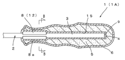
- the grip 1 ⁇ / b> A of the first embodiment is provided at the rear part 3 of the tool shaft 2 and is formed in a substantially spheroid shape that is long along the axial direction of the tool shaft 2.
- the grip 1 ⁇ / b> A includes an inner layer 4 that surrounds the rear portion 3 having the fin 8 (detent portion 12) of the tool shaft 2, a grip body 5 that surrounds the periphery of the inner layer 4, and a periphery of the grip body 5.
- the covering layer 6 is made of a softer resin than the grip body 5, and the inner layer 4 is made of the same resin as the covering layer 6. That is, the grip 1 ⁇ / b> A has a configuration in which the inner layer 4 made of a softer resin than the grip body 5 is provided between the grip body 5 and the rear portion 3 of the tool shaft 2.
- the grip body 5 is formed in a substantially oval shape similar in appearance to the grip 1A in accordance with the appearance shape of the grip 1A, and is formed in a size smaller by the thickness of the covering layer 6 than the grip 1A. Yes.
- the grip body 5 surrounds the inner layer 4 formed in accordance with the shape of the rear portion 3 of the tool shaft 2 from the outside. That is, the grip body 5 is formed in a bottomed cylindrical shape that opens toward the front, and is also formed on the rear end side of the inner layer 4 that surrounds the shaft rear end face 9 of the rear portion 3.
- the covering layer 6 covers the entire outer peripheral surface, front end surface, and rear end surface of the grip body 5.
- the covering layer 6 is integrally formed of the same resin as that of the inner layer 4 and is connected to the inner layer 4 on the tip side, and surrounds the outer diameter side of the grip body 5 without a gap.
- the inner layer 4 is formed in a substantially cylindrical shape so as to surround the entire outer peripheral surface, front end surface, and rear end surface of the rear portion 3 of the tool shaft 2, and can surround the entire surface of the shaft rear end surface 9 of the rear portion 3. Thus, it is formed also on the rear end side of the shaft rear end surface 9.
- the inner layer 4 of the grip 1 ⁇ / b> A has a shape that swells toward the outside of the diameter in accordance with the fin 8 at the position where the fin 8 is formed on the tool shaft 2. Besieged. As shown in FIG. 3, in the grip 1 ⁇ / b> A, the grip body 5 is formed of a hard resin, and the inner layer 4 and the covering layer 6 are formed of a soft resin softer than the hard resin constituting the grip body 5. ing. In other words, the grip 1 ⁇ / b> A surrounds the rear portion 3 of the tool shaft 2 by forming a member having a grip body 5 sandwiched between the inner layer 4 and the covering layer 6 in a bottomed cylindrical shape.
- Examples of the soft resin forming the inner layer 4 and the covering layer 6 include silicon rubber, natural rubber, synthetic rubber such as BR and SBR, polyethylene resin, ionomer resin, ethylene-propylene copolymer, polyurethane foam, or A synthetic resin obtained by mixing a plurality of resins selected from these is used.
- a synthetic resin having a Shore A hardness (ASTM D2240) of 40 to 60 is preferably used.
- ASTM D2240 Shore A hardness
- a synthetic resin having a Shore A hardness of 40 or more as the hard resin the occurrence of bleeding can be prevented.
- a synthetic resin having a Shore A hardness of 60 or less as the hard resin it is possible to reduce the burden on fingers when gripping and using.
- the hard resin forming the grip body 5 includes a polypropylene resin having a Rockwell hardness (ASTM D785) of 80 to 100, a polystyrene resin, ABS, an acetylene resin, or a synthetic resin in which a plurality of resins selected from these are mixed, Alternatively, recycled resins containing these resins are used, and among these, polypropylene resins are particularly preferable.
- a synthetic resin having a Rockwell hardness of 80 to 100 is preferably used. If a hard resin having such hardness is used for the grip body 5, the rotational torque generated when the grip 1A is twisted can be transmitted to the tool shaft 2 without being reduced even if the inner layer 4 is interposed. It becomes.
- the recycled material is used in a proportion less than 10%.
- the use ratio of the material can be increased to 90% or more, and the load on the environment can be reduced.
- the grip body 5 is covered with the coating layer 6.
- the grip 1A can be color-coded according to the size and type.
- the inner layer 4 made of a soft resin is provided between the grip body 5 made of a hard resin and the rear part 3 of the tool shaft 2 as described above, the inner side of the tool shaft 2 inserted into the grip 1A is provided. Since the layer 4 gives an appropriate resistance to coming off, there is no fear that the tool shaft 2 will fall out of the grip 1A and fall or be lost. Further, if the tool shaft 2 is pushed and pulled strongly with respect to the grip 1A with a force exceeding the pull-out resistance provided by the inner layer 4, the tool shaft 2 slides with respect to the grip 1A and the tool shaft 2 is inserted and removed. The tool shaft 2 can be easily replaced.
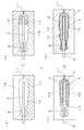
- the grip 1 ⁇ / b> A is manufactured by a two-color injection molding method (mixed-color molding method) in which the rear portion 3 of the tool shaft 2 is inserted into the chamber 14 of the mold 10 and molten resin is supplied into the chamber 14.
- the mold 10 is provided with a chamber 14 that is formed hollow in accordance with the external shape of the grip 1A.
- a supply port 11 for supplying molten resin is formed on the rear end side of the chamber 14.
- a soft resin (first resin) for forming the inner layer 4 and the coating layer 6 is supplied in a molten state to the supply port 11.
- the hard resin (second resin) is supplied into the chamber 14 from the supply port 11 in a molten state.
- the hard resin is supplied to the inside of the resin reservoir of the soft resin already supplied so that the soft resin is inflated with the hard resin from the inside.
- the soft resin first adheres to the inner peripheral surface of the chamber 14 and the outer surface of the tool shaft 2 to form the inner layer 4 and the coating layer 6 connected to the inner layer 4 on the tip side.
- the grip 1A is manufactured by a color mixture molding method in which a soft resin is first supplied and the soft resin is continuously supplied to the inside of the soft resin. That is, since the hard resin and the soft resin are continuously supplied, it is not necessary to spend time for cooling the resin after supplying each resin. As a result, the grip 1A formed in multiple layers with different resins can be manufactured at once (efficiently).
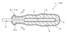
- the grip 1B of the second embodiment is already formed so that the fin 8 penetrates the inner layer 4 and reaches the grip body 5 when the rear part 3 of the tool shaft 2 with the fin 8 of the tool is inserted from the tip side.
- a straight cylindrical inner layer 4 that is inserted into the inner layer 4 of the grip 1B from the front end side and opened toward the front is provided.
- the inner layer 4 is formed in a straight cylindrical shape that opens toward the front, and does not swell toward the outside of the diameter in accordance with the fin 8 even at the position where the fin 8 of the tool shaft 2 is formed.
- the rear end of the inner layer 4 is positioned further to the rear end side than the rear end surface of the tool shaft 2, and a resin or a tool is provided between the rear end surface of the tool shaft 2 and the rear end of the inner layer 4. Not a space is formed.
- the tool shaft 2 inserted from the front end side of the grip 1B reaches the grip body 5 formed of hard resin with the front end (protruding end 8a) of the fin 8 penetrating the inner layer 4, and the fin 8 A pull-out resistance is generated between the surrounding inner layer 4 and the fin 8.
- the grip 1B is manufactured using the mold 10 of the first embodiment as it is.
- a tool shaft insert is inserted into the internal chamber 14 instead of the tool shaft 2 with the fins 8.
- This tool shaft insert uses a round bar in which the fins 8 are not formed, and is disposed in the chamber 14 so that the rear end thereof is located on the rear end side of the chamber 14.
- a soft resin is supplied from the supply port 11 into the chamber 14, and then the hard resin is supplied from the supply port 11 into the chamber 14 following the supply of the soft resin. . At that time, the hard resin is supplied to the inside of the resin reservoir of the soft resin.
- the tool shaft insert is extracted from the grip 1B formed in this way. After the tool shaft insert is extracted, a straight cylindrical shaft hole 15 opened toward the tip side is formed along the axial direction. Then, the tool shaft 2 with fins 8 to be actually used is inserted into the shaft hole 15 from the shaft rear end face 9.
- the inner layer 4 is cut by the fin 8 in accordance with the insertion of the tool shaft 2.
- the inner layer 4 surrounding the fin 8 and the fin 8 are in contact with each other.
- the grip 1 ⁇ / b> B can be manufactured by freely combining various types of tool shafts 2 with respect to the shaft holes 15. Therefore, it is convenient when manufacturing various types of tools. Further, since a tool shaft insert is used instead of the tool shaft 2 in the process of being heated to a high temperature by the molten resin, the tool shaft 2 has a metal material having no heat resistance (for example, a metal material including a heat-resistant neodymium magnet) ) And various types of tools can be easily manufactured. “Third Embodiment” Next, the grip 1C of the third embodiment will be described with reference to FIG.
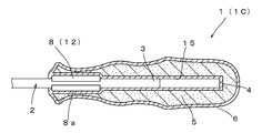
- the grip 1C uses the mold 10 of the first embodiment, and performs molding by supplying resin in a state where the tool shaft insert is inserted into the chamber 14 instead of the tool shaft 2 as in the second embodiment. After that, the tool shaft insert is pulled out to form a shaft hole 15, and the tool shaft 2 is inserted into the shaft hole 15.
- the grip 1C is different from the first and second embodiments in that the tool shaft insert is formed by forming a fin 8 on a round bar, and the fin 8 is provided in the shaft hole 15 formed by the tool shaft insert. A round bar-shaped tool shaft 2 is inserted.
- the tool shaft 2 has an axial length shorter than that of the tool shaft insert, and the rear end surface of the tool shaft 2 is located on the front side of the rear end surface of the shaft hole 15.
- the rear portion 3 of the tool shaft 2 is in contact with only the front end side (a part) of the inner layer 4 so as to exhibit a resistance to pulling out.
- the grip 1C by changing the length of the tool shaft 2, the length of the tool shaft 2 that comes into contact with the inner layer 4 and exhibits the pull-out resistance can be changed. Can be changed arbitrarily. “Fourth Embodiment” Next, the grip 1D of the fourth embodiment will be described with reference to FIG.
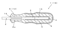
- the inner layer 4 and the covering layer 6 are not formed between the rear end side and the front end side of the grip body 5, but are formed between the rear end side and the middle part of the grip body 5. Has been. And on the front end side of the grip 1D, the inner layer 4 is not provided between the rear portion 3 of the tool shaft 2 and the grip main body 5, and the grip main body 5 includes the rotation stop portion 12 of the tool shaft 2. The structure is in direct contact with the rear portion 3.
- the shaft hole 15 into which the rear part 3 of the tool shaft 2 in the grip 1D is inserted is covered only with the inner layer 4 on the rear side, and the inner layer 4 is not provided on the tip side.
- the rear end surface of the tool shaft 2 inserted into the grip 1D is located on the front end side from the rear end surface of the shaft hole 15 as in the third embodiment, and the rear end side (partially) of the rear portion 3 of the tool shaft 2 ) Is covered with an inner layer 4 formed on the rear end side of the shaft hole 15, and the front end side of the rear portion 3 of the tool shaft 2 is covered with a grip body 5 made of hard resin.
- a fin insertion groove 16 is formed along the axial direction of the tool shaft 2 on the inner peripheral surface on the tip end side of the shaft hole 15 so that the fin 8 of the tool shaft 2 can be inserted.
- the manufacturing method of 4th Embodiment is demonstrated below.
- the tool shaft 2 or the tool shaft insert is disposed in the chamber 14, and the soft resin is supplied to the supply port 11 Into the chamber 14.
- the hard resin is supplied into the chamber 14 from the supply port 11 following the supply of the soft resin, the hard resin is supplied inside the resin reservoir of the soft resin.
- the supply amount of the soft resin supplied first is reduced, and the supply amount of the hard resin supplied later is increased.
- the resin reservoir of the soft resin supplied earlier stays on the rear end side of the chamber 14, and only the hard resin supplied later penetrates the resin reservoir.
- the inner layer 4 and the covering layer 6 can be formed only between the rear end side and the midway part of the grip body 5.
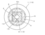
- the grip 1 ⁇ / b> E is provided with a tool shaft 2 having a socket 17 so as to be detachable, and an inner layer 4 is provided between the outer peripheral surface of the socket 17 and the grip body 5.
- the socket 17 is formed in a rectangular tube shape, and a flange portion 19 is formed on the tip side thereof.
- An insertion hole 18 through which the tool shaft 2 is inserted is formed in the socket 17 along the axial direction.
- a fin insertion groove 16 is formed in the insertion hole 18 in parallel with the axis, and the rear portion 3 of the tool shaft 2 can be detachably inserted by guiding the fin 8 along the fin insertion groove 16. It is like that.
- the outer peripheral surface of the socket 17 is inserted into a shaft hole 15 formed in accordance with the outer diameter of the socket 17, and the outer peripheral surface of the socket 17 contacts the inner layer 4 so that the tool shaft having the socket 17 is provided.
- the pull-out resistance works in 2.
- the tool shaft 2 can be inserted into and removed from the grip 1E together with the socket 17.
- the socket 17 can be replaced, so that the convenience of the tool and the grip 1E can be further improved.
- a manufacturing method of the grip 1E will be described below.
- a tool shaft insert adapted to the outer shape of the rectangular tube portion of the socket 17 is previously inserted into the inner chamber 14 of the mold 10.
- the tool shaft insert is formed to have a length extending from the front end of the chamber 14 to the rear end, and is tapered toward the front end so that the socket 17 can be easily inserted and removed later.
- a soft resin and a hard resin are supplied into the chamber 14 from the supply port 11, and the inner layer 4, the grip body 5, and the coating layer are provided around the tool shaft insert. 6 is formed.
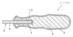
- the grip 1F includes a hexagonal cylindrical inner layer 4, a hexagonal bar-shaped (square axis) tool axis 2 is inserted as the tool axis 2, and the hexagonal cylindrical inner layer 4 is a hexagonal bar-shaped tool axis. Since each surface of 2 is covered, a constant torque can be transmitted in the rotation direction even though the tool shaft 2 can be easily pulled out.
- the grip 1 ⁇ / b> F is a grip that is detachably provided on the angular shaft-shaped tool shaft 2 whose corner portion is the anti-rotation portion 12.
- the grip 1F may be provided with a rectangular cylindrical inner layer 4 into which a square rod-shaped tool shaft 2 can be inserted, for example. “Seventh Embodiment” Next, the grip 1G of 7th Embodiment is demonstrated based on FIG.
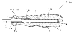
- the grip 1G is provided with a tool shaft 2 having a socket 17 in a detachable manner, like the grip 1E of the fifth embodiment.
- the inner layer 4 and the covering layer 6 are formed between the rear end side and the midway portion of the grip body 5, and between the socket 17 and the grip body 5 at the front end side of the grip 1G.
- the inner layer 4 is not provided, and the grip body 5 is in direct contact with the outer peripheral surface of the socket 17.
- the tip end side of the shaft hole 15 is formed in a shape matching the outer diameter of the socket 17 (the rectangular tube portion of the socket 17), and the rear end side of the shaft hole 15 is the outer diameter of the tool shaft 2.
- the manufacturing method of the grip 1G uses a tool shaft insert that matches the outer shape of the rear end side (square tube portion) of the socket 17 instead of the round rod-shaped tool shaft insert in the manufacturing method of the fourth embodiment. That is, the tip end side of the tool shaft insert of the grip 1G is formed in a shape matching the square tube portion of the socket 17, and the rear end side is formed in a columnar shape having a smaller diameter than the tip end according to the outer diameter of the tool shaft 2. Is formed.
- the socket 17 is formed on the front end side of the shaft hole 15 formed by pulling out the tool shaft insert, and the rear portion 3 of the tool shaft 2 on the rear end side.
- the grip 1G can be manufactured by inserting. “Eighth Embodiment” Next, the grip 1H of the eighth embodiment will be described with reference to FIGS.
- the grip 1H is a single grip that does not include the tool shaft 2.
- the grip 1H has a shaft hole 15 that opens toward the tip side.
- a fin insertion groove 16 is formed in the shaft hole 15 from the middle side to the tip side of the shaft hole 15 so that the rear part 3 of the tool shaft 2 having the fins 8 can be inserted.
- Layer 4 is formed.
- the covering layer 6 is formed over the entire length from the front end side to the rear end side of the grip body 5, whereas the inner layer 4 is formed only on the front end side of the grip body 5.
- the grip body 5 is connected at the front end side.
- the inner layer 4 is formed so that its thickness gradually decreases from the front end side toward the rear end side, and is not formed on the rear end side from the midway side of the fin insertion groove 16.
- the inner layer 4 is formed only on the front end side of the grip body 5, the pulling resistance generated between the tool shaft 2 and the inner layer 4 when the rear portion 3 is inserted can be reduced.
- the tool shaft 2 can be inserted and removed without applying force, and the tool shaft 2 can be easily replaced.
- the manufacturing method of the grip 1H As shown in FIG. 14A, first, soft resin and hard resin are sequentially injected from the supply port 11 into the chamber 14 in which the tool shaft insert 26 is not inserted.
- a shaft insertion portion 20 for inserting a tool shaft insert 26 with fins 8 is formed in the mold 10 on the distal end side of the chamber 14, and the tool shaft insert 26 closes the shaft insertion portion 20 when resin is injected.
- the resin injected into the chamber 14 does not leak from the shaft insertion portion 20 to the outside of the chamber 14.
- the tool shaft insert 26 is inserted into the chamber 14 before cooling and solidification of the filled resin starts. To do. At this time, the tool shaft insert 26 is inserted into the chamber 14 while winding the coating layer 6 formed on the front end side of the chamber 14, and the inner layer 4 is formed of the same soft resin as the coating layer 6 around the tool shaft insert 26. Is done.
- the inner layer 4 is formed around the tool shaft insert 26, and the fins 8 are formed in accordance with the formation of the inner layer 4.
- the fin insertion groove 16 is formed in the inner layer 4, and the tool shaft insert 26 breaks the inner layer 4 and penetrates into the grip body 5.
- the tool shaft insert 26 is pulled out of the chamber 14 to pull the shaft hole 15 into the inner layer 4 and the grip body 5. Is formed.
- the soft resin and the hard resin filled in the chamber 14 are not completely cooled and solidified. 6, the inner layer 4 can be easily formed around the tool shaft insert 26, and the grip 1H in which the inner layer 4 is formed only on the front end side of the chamber 14 is easily manufactured. It becomes possible to do.
- the present invention is not limited to the above-described embodiments, and the shape, structure, material, combination, and the like of each member can be appropriately changed without changing the essence of the invention.
- the soft resin and the hard resin include silicon rubber and polypropylene resin, but the soft resin and the hard resin are not limited to those described above. For example, a mixture of a plurality of resins or a recycled resin can be used.
- the fins 8 of the tool shaft 2 are illustrated as plate-like ones formed in the radial direction with the axis of the tool shaft 2 sandwiched between the rear portions 3.
- the fins 8 may be continuous protrusions in the axial direction and the circumferential direction.
- three or more sheets may be formed.
- the inner layer 4 and the coating layer 6 are illustrated by injecting two types of resins from the supply port 11 provided on the rear end side of the chamber 14.
- these supply ports 11 may be provided in the middle or the front end side of the chamber 14, and one or a plurality of supply ports 11 at each position may be formed, and two types of resins are supplied from each supply port 11. It only needs to be injected.
- the grip 1 that gives the resistance to the tool shaft 2 only by the inner layer 4 is illustrated.
- the tool shaft 2 penetrates the grip body 5 and the inner layer 4 from the outer peripheral side of the coating layer 6. It is also possible to give a strong pulling resistance to the tool shaft 2 using a locking tool such as a screw or a bolt that reaches
Landscapes
- Engineering & Computer Science (AREA)
- Mechanical Engineering (AREA)
- Manufacturing & Machinery (AREA)
- Injection Moulding Of Plastics Or The Like (AREA)
- Moulds For Moulding Plastics Or The Like (AREA)
- Fishing Rods (AREA)
- Portable Power Tools In General (AREA)
Abstract
Description
しかし、工具には古くなった工具軸を新たな工具軸に取り替えたいという要望や工具軸だけを刃先の形状が異なる別の工具軸に取り替えたいという要望がある。それゆえ、工具軸の抜き挿しが困難な従来の工具では、上述の要望に応えることができない。
ところが、このような工具では、工具軸を容易に挿入できる反面、何らかの拍子に抜け落ちることもある。例えば作業時に工具を傾けた際に工具軸が簡単に抜け落ちてしまうようでは作業性を低下させてしまうので好ましくない。つまり、工具には、工具軸が挿脱自在でありながら、簡単には抜け落ちてしまわないように工具軸に適度な抜け抵抗が与えられるようになっているのが好ましい。
また、本発明は、グリップを嵌着していながら工具軸を簡単に交換することができ、工具軸の落下を防止して良好な作業性を実現できる工具を提供することを目的とする。
すなわち、本発明のグリップは、工具軸の回り止め部を有する後部を包囲するグリップ本体と、このグリップ本体より軟質な樹脂で前記グリップ本体の周囲を被覆する被覆層とを備えた工具のグリップであって、前記グリップ本体と工具軸の後部との間に前記被覆層と同一の樹脂で形成された内部層を備えていることを特徴とする。
このようにすれば、グリップ本体との間に設けられた内部層がソケットの外周面に抜け抵抗を与えるため、ソケットごと工具軸をグリップから抜き差しすることが可能となり、ソケットを有する工具軸の交換が可能となる。
さらに、本発明の樹脂注入後に工具軸入れ子を挿入するグリップの製造方法は、金型のチャンバ内に供給口から第1の樹脂を注入し、前記第1の樹脂の注入途中から当該第1の樹脂より硬質な第2の樹脂を前記供給口から注入し、前記第1の樹脂でチャンバの内周面に沿って被覆層を形成すると共に前記被覆層の内側にグリップ本体を形成し、前記チャンバ内に充填された第1及び第2の樹脂が冷却固化する前に工具軸入れ子を前記被覆層を巻き込みながら前記チャンバに挿入して前記工具軸入れ子の周囲に内部層を形成し、前記軸穴の形成後に、前記工具軸入れ子を前記チャンバから引き抜くことにより、前記内部層の内側に軸穴を形成することを特徴とする。
このようにすれば工具軸の回り止め部を備えた後部をグリップ本体より軟質な樹脂で形成された内部層で包囲することができる。
また、前記第1の樹脂を前記チャンバの後端側から中途側まで流入させ、前記第2の樹脂を前記チャンバの後端側から先端側まで流入させることもできる。
また、本発明の工具によれば、工具軸を簡単に交換することができ、工具軸の落下を防止して良好な作業性を実現できる。
さらに、本発明のグリップの製造方法によれば、工具軸を挿脱可能に保持できるグリップを低コストで製造することができる。
工具は、工具軸2の後部3にグリップ1を嵌着して構成されている。前記工具軸2は、丸棒材から形成されており、先端側にビス等と係合可能な刃先が形成されている。また、工具軸2の後部3には工具軸2をグリップ1に対して回り止めする回り止め部12が設けられており、グリップ1の回転トルクを工具軸2に伝達できるようになっている。回り止め部12としてフィン8が形成されており、このフィン8は、工具軸2の後部3に工具軸2の軸心を挟んで径方向に一対形成されている。フィン8は、後部3の外周面の一部をプレスで圧縮成形することで後部3の外周面から径外方向に板状に突出形成されており、グリップに対する工具軸2の相対回転を規制している。
被覆層6はグリップ本体5より軟質な樹脂で形成されており、内部層4は被覆層6と同一の樹脂で形成されている。つまり、グリップ1Aは、グリップ本体5より軟質な樹脂で構成された内部層4を、グリップ本体5と工具軸2の後部3との間に積層状に備えた構成とされている。
グリップ本体5は、工具軸2の後部3の形状に合わせて形成された内部層4を外側から包囲している。すなわち、グリップ本体5は、先方に向かって開口した有底筒状に形成されており、後部3の軸後端面9を包囲する内部層4のさらに後端側にも形成されている。
内部層4は、工具軸2の後部3の外周面、前端面及び後端面を全面に亘って包囲するように略円筒状に形成されており、後部3の軸後端面9の全面を包囲できるように軸後端面9の後端側にも形成されている。
図3に示すように、グリップ1Aでは、グリップ本体5は硬質の樹脂で形成されており、内部層4と被覆層6とはグリップ本体5を構成する硬質の樹脂より柔らかい軟質の樹脂で形成されている。言い換えれば、グリップ1Aは内部層4と被覆層6との間にグリップ本体5を挟持した部材を有底の円筒状に形成して、工具軸2の後部3の周りを包囲している。
軟質の樹脂には、ショアA硬さ(ASTM D2240)が40~60の合成樹脂を用いるのが好ましい。ショアA硬さ40以上の合成樹脂を硬質の樹脂に用いることで、ブリードの発生を防ぐことができる。また、ショアA硬さ60以下の合成樹脂を硬質の樹脂に用いることで、握って使用する際の手指に対する負担を軽減することが可能となるからである。
硬質の樹脂には、ロックウェル硬さが80~100の合成樹脂を用いるのが好ましい。これらの硬度を備えた硬質の樹脂をグリップ本体5に用いれば、内部層4を介在していても、グリップ1Aを捻った際に発生する回転トルクを工具軸2に減らすことなく伝えることが可能となる。
グリップ1Aの製造方法は、金型10のチャンバ14に工具軸2の後部3を挿入し、チャンバ14内に溶融状態の樹脂を供給する二色射出成型法(混色成型法)で製造される。
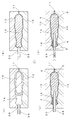
図4(a)に示すように、金型10には、内部がグリップ1Aの外観形状に合わせて中空に形成されたチャンバ14が設けられている。チャンバ14には、溶融した樹脂を供給する供給口11が後端側に形成されている。
図4(c)に示すように、軟質の樹脂の供給に続いて、硬質の樹脂(第2の樹脂)を溶融状態のまま供給口11からチャンバ14内に供給する。このとき、既に供給された軟質の樹脂の樹脂溜まり内側に硬質の樹脂を供給して、軟質の樹脂を内部から硬質の樹脂で膨らませるようにする。このようにすると、軟質の樹脂がチャンバ14の内周面や工具軸2の外表面に最初に付着して、内部層4とこの内部層4に先端側で繋がった被覆層6とが形成される。
このようにグリップ1Aは、軟質の樹脂を最初に供給し、軟質の樹脂の内側に軟質の樹脂を連続して供給する混色成型法で製造される。つまり、硬質の樹脂と軟質の樹脂とが連続して供給されているので、それぞれの樹脂の供給後に樹脂の冷却に時間をかける必要がない。その結果、異なる樹脂で多層に形成されたグリップ1Aを一度に(効率的に)製造することができる。
「第2実施形態」
次に、第2実施形態を図5、6に基づき説明する。
グリップ1Bでは、内部層4は先方に向かって開口したストレート筒状に形成されており、工具軸2のフィン8が形成された位置でもフィン8に合わせて径外側に向かって膨らむことがない。また、内部層4の後端は工具軸2の後端面よりさらに後端側に位置しており、工具軸2の後端面と内部層4の後端との間には樹脂や工具が設けられていない空間が形成されている。
次に、第2実施形態の製造方法を以下に説明する。
グリップ1Bは、第1実施形態の金型10をそのまま使用して製造される。金型10には内部のチャンバ14にフィン8付きの工具軸2に代えて工具軸入れ子が挿入される。この工具軸入れ子は、フィン8が形成されていない丸棒を使用し、その後端がチャンバ14の後端側に位置するようにチャンバ14内に配備する。
次に、このようにして形成されたグリップ1Bから工具軸入れ子を抜き出す。工具軸入れ子を抜き出した後には、先端側に向かって開口したストレート筒状の軸穴15が軸心方向に沿って形成される。そして、この軸穴15に、実際に使用するフィン8付き工具軸2を軸後端面9から挿入する。フィン8付きの工具軸2はフィン8の突端8a間の外径が軸穴15の内径より大きくなっているため、工具軸2の挿入に合わせて内部層4にはフィン8による切り込みが入り、フィン8を取り巻く内部層4とフィン8とが互いに接触する。
また、硬質な樹脂で成るグリップ本体5に工具軸2のフィン8の突端8aが達しているので、グリップ1Bに加えられた回転トルクを、内部層4に吸収されることなく工具軸2に確実に伝えることができる。
「第3実施形態」
次に、第3実施形態のグリップ1Cを図7に基づいて説明する。
グリップ1Cが第1及び第2実施形態と異なっている点は、工具軸入れ子が丸棒にフィン8が形成されたものとされており、工具軸入れ子が形成した軸穴15にフィン8を備えた丸棒状の工具軸2が挿入されている点である。
グリップ1Cでは、工具軸2の長さを変更することで内部層4と接触して抜け抵抗を発揮する工具軸2の長さを変更することができ、工具軸2に働く抜け抵抗の大きさを任意に変更することができる。
「第4実施形態」
次に、第4実施形態のグリップ1Dを図8に基づいて説明する。
グリップ1Dを成形するには、第1~第3実施形態の場合と同様の金型10を使用し、チャンバ14内に工具軸2又は工具軸入れ子を配置し、そして軟質の樹脂を供給口11からチャンバ14内に供給する。軟質の樹脂の供給に続いて硬質の樹脂を供給口11からチャンバ14内に供給する際に、軟質の樹脂の樹脂溜まりの内側に硬質の樹脂を供給する。先に供給される軟質の樹脂の供給量を少なくし、後から供給される硬質の樹脂の供給量が多くする。このように軟質の樹脂の供給量を少なくすると、先に供給された軟質の樹脂の樹脂溜まりがチャンバ14の後端側に留まり、後から供給された硬質の樹脂だけが樹脂溜まりを貫通してチャンバ14の先端側に広がり、内部層4と被覆層6とをグリップ本体5における後端側から中途部までの間だけに形成することができる。
「第5実施形態」
次に、第5実施形態のグリップ1Eを図9、10に基づいて説明する。
ソケット17は角筒状に形成されており、その先端側にはフランジ部19が形成されている。ソケット17の内部には、工具軸2を挿通する挿通孔18が軸心方向に沿って形成されている。この挿通孔18には、軸心と平行にフィン挿入溝16が形成されており、このフィン挿入溝16に沿ってフィン8を案内することで、工具軸2の後部3を着脱自在に挿入できるようになっている。
このようにすれば、グリップ本体5とソケット17の外周面との間に設けられた内部層4がソケット17に抜け抵抗を与えるため、ソケット17ごと工具軸2をグリップ1Eから抜き差しすることが可能となり、工具軸2の交換だけでなくソケット17の交換も可能となるので、工具やグリップ1Eの利便性をさらに向上させることができる。
グリップ1Eを製造するには、金型10には内部のチャンバ14に、ソケット17の角筒部の外形に合わせた工具軸入れ子を予め挿入しておく。この工具軸入れ子は、チャンバ14の先端から後端際まで及ぶ長さに形成されており、またあとでソケット17を挿脱し易いように先端側に向かってテーパ状に形成されている。そして、上述の実施形態の場合と同様に、まず軟質の樹脂と硬質の樹脂とを供給口11からチャンバ14内に供給して、工具軸入れ子の周囲に内部層4、グリップ本体5、被覆層6を形成する。そして、冷却後に工具軸入れ子を抜き取り、抜き取ったあとの軸穴15に工具軸2とこの工具軸2が挿入されたソケット17とを挿入する。
「第6実施形態」
次に、第6実施形態のグリップ1Fを図11に基づいて説明する。
すなわち、グリップ1Fは、角部が回り止め部12とされた角軸状の工具軸2に着脱自在に備えられるグリップである。このグリップ1Fは、例えば四角棒状の工具軸2を挿入可能な四角筒状の内部層4を備えたものであっても良い。
「第7実施形態」
次に、第7実施形態のグリップ1Gを図12に基づいて説明する。
「第8実施形態」
次に、第8実施形態のグリップ1Hを図13、14に基づいて説明する。
被覆層6がグリップ本体5の先端側から後端側までの全長に亘って形成されているのに対して、内部層4はグリップ本体5の先端側だけに形成されており、被覆層6とグリップ本体5の先端側で繋がっている。内部層4は、その厚みが先端側から後端側に向かって徐々に薄くなるように形成されており、フィン挿入溝16の中途側より後端側には形成されていない。このように内部層4がグリップ本体5の先端側だけに形成されていれば、工具軸2の後部3を挿入した際に内部層4との間に生じる引き抜き抵抗を小さくすることができ、強い力をかけなくても工具軸2の挿脱が行えるようになって、工具軸2の付け替えを楽に行うことができる。
グリップ1Hの製造方法は、図14(a)に示されるように、まず工具軸入れ子26が挿入されていないチャンバ14内に軟質の樹脂及び硬質の樹脂を供給口11から順次注入する。チャンバ14の先端側の金型10にはフィン8付きの工具軸入れ子26を挿入する軸挿入部20が形成されており、樹脂の注入時にはこの軸挿入部20を工具軸入れ子26が塞ぐことでチャンバ14に注入された樹脂が軸挿入部20からチャンバ14の外部に漏れないようになっている。
図14(d)に示されるように、軟質の樹脂及び硬質の樹脂が冷却されて固化し始めたら工具軸入れ子26をチャンバ14から引き抜くことにより内部層4及びグリップ本体5の内側に軸穴15が形成される。
軟質の樹脂や硬質の樹脂としてシリコンゴムやポリプロピレン系樹脂などを例示したが、軟質の樹脂や硬質の樹脂は上述のものに限定されることはない。例えば、複数の樹脂の混合物や再生樹脂を用いることもできる。
上記実施形態では、内部層4と被覆層6とが2種類の樹脂をチャンバ14の後端側に設けられた供給口11から注入して形成されたものを例示した。しかし、これらの供給口11はチャンバ14の中途側や先端側に設けられても良いし、各位置の供給口11は1又は複数形成しても良く、各供給口11から2種類の樹脂を注入できれば良い。
2 工具軸
3 後部
4 内部層
5 グリップ本体
6 被覆層
8 フィン
8aフィンの突端
9 工具軸の軸後端面
10 金型
11 供給口
12 回り止め部
14 チャンバ
15 軸穴
16 フィン挿入溝
17 ソケット
18 挿通孔
19 フランジ部
20 軸挿入部
Claims (11)
- 工具軸の回り止め部を有する後部を包囲するグリップ本体と、このグリップ本体より軟質な樹脂で前記グリップ本体の周囲を被覆する被覆層とを備えたグリップであって、
前記グリップ本体と工具軸の後部との間に、前記被覆層と同一の樹脂で形成された内部層を備えていることを特徴とするグリップ。 - 前記工具軸の後部に備えたソケットの外周面と前記グリップ本体との間に前記内部層が設けられていることを特徴とする請求項1に記載のグリップ。
- 前記内部層と被覆層とは前記グリップ本体における後端側から先端側までの間に形成され且つ先端側で内部層と被覆層とが連続形成されていることを特徴とする請求項1又は2に記載のグリップ。
- 前記内部層と被覆層とは前記グリップ本体における後端側から中途部までの間に形成されていることを特徴とする請求項1又は2に記載のグリップ。
- 請求項1~4のいずれかに記載のグリップを工具軸の後部に備えていることを特徴とする工具。
- 前記工具軸の後部は、角軸に形成している、丸軸にフィンを設けている、又は丸軸にフィンを設けてさらにソケットを嵌合していることを特徴とする請求項5に記載の工具。
- 工具軸の回り止め部を備えた後部を金型のチャンバ内に挿入し、
前記チャンバ内に供給口から第1の樹脂を注入し、
前記第1の樹脂の注入途中から、当該第1の樹脂より硬質な第2の樹脂を前記供給口から注入し、
前記第1の樹脂でチャンバの内周面に沿って被覆層を形成すると共に前記工具軸の後部の周囲に内部層を形成し、
前記第2の樹脂で被覆層と内部層との間にグリップ本体を形成することを特徴とするグリップの製造方法。 - 工具軸入れ子を金型のチャンバ内に挿入し、
前記チャンバ内に供給口から第1の樹脂を注入し、
前記第1の樹脂の注入途中から、当該第1の樹脂より硬質な第2の樹脂を前記供給口から注入し、
前記第1の樹脂でチャンバの内周面に沿って被覆層を形成すると共に前記工具軸入れ子の周囲に内部層を形成し、
前記第2の樹脂で被覆層と内部層との間にグリップ本体を形成することを特徴とするグリップの製造方法。 - 金型のチャンバ内に供給口から第1の樹脂を注入し、
前記第1の樹脂の注入途中から、当該第1の樹脂より硬質な第2の樹脂を前記供給口から注入し、
前記第1の樹脂でチャンバの内周面に沿って被覆層を形成すると共に前記被覆層の内側にグリップ本体を形成し、
前記チャンバ内に充填された第1及び第2の樹脂が冷却固化する前に、工具軸入れ子を前記被覆層を巻き込みながら前記チャンバに挿入して、前記工具軸入れ子の周囲に内部層を形成し、
前記内部層の形成後に、前記工具軸入れ子を前記チャンバから引き抜くことにより、前記内部層の内側に軸穴を形成することを特徴とするグリップの製造方法。 - 前記第1の樹脂と前記第2の樹脂とを前記チャンバの後端側から先端側まで流入させることを特徴とする請求項7~9のいずれかに記載のグリップの製造方法。
- 前記第1の樹脂を前記チャンバの後端側から中途側まで流入させ、
前記第2の樹脂を前記チャンバの後端側から先端側まで流入させることを特徴とする請求項7又は8に記載のグリップの製造方法。
Priority Applications (2)
| Application Number | Priority Date | Filing Date | Title |
|---|---|---|---|
| EP10750876.4A EP2407280A4 (en) | 2009-03-13 | 2010-03-10 | HANDLE, TOOL AND METHOD FOR THE PRODUCTION THEREOF |
| CN201080011358.4A CN102348540B (zh) | 2009-03-13 | 2010-03-10 | 把手、工具及把手的制造方法 |
Applications Claiming Priority (2)
| Application Number | Priority Date | Filing Date | Title |
|---|---|---|---|
| JP2009061304A JP4440327B1 (ja) | 2009-03-13 | 2009-03-13 | グリップ、工具及びグリップの製造方法 |
| JP2009-061304 | 2009-03-13 |
Publications (1)
| Publication Number | Publication Date |
|---|---|
| WO2010104123A1 true WO2010104123A1 (ja) | 2010-09-16 |
Family
ID=42193865
Family Applications (1)
| Application Number | Title | Priority Date | Filing Date |
|---|---|---|---|
| PCT/JP2010/054021 Ceased WO2010104123A1 (ja) | 2009-03-13 | 2010-03-10 | グリップ、工具及びグリップの製造方法 |
Country Status (6)
| Country | Link |
|---|---|
| EP (1) | EP2407280A4 (ja) |
| JP (1) | JP4440327B1 (ja) |
| KR (1) | KR20110135952A (ja) |
| CN (1) | CN102348540B (ja) |
| TW (1) | TWI422472B (ja) |
| WO (1) | WO2010104123A1 (ja) |
Cited By (2)
| Publication number | Priority date | Publication date | Assignee | Title |
|---|---|---|---|---|
| WO2014062821A1 (en) * | 2012-10-16 | 2014-04-24 | The Methodist Hospital | Multiplexed volumetric bar chart chip for point of care biomarker and/or analyte quantitation |
| DE102016212247A1 (de) * | 2016-07-05 | 2018-01-11 | Wiha Werkzeuge Gmbh | Bit für ein Schraubwerkzeug und Verfahren zu dessen Herstellung |
Families Citing this family (7)
| Publication number | Priority date | Publication date | Assignee | Title |
|---|---|---|---|---|
| PL2868438T3 (pl) * | 2013-11-04 | 2023-07-24 | Fiskars Finland Oy Ab | Trzonek i sposób wytwarzania trzonka |
| IL230808A0 (en) * | 2014-02-04 | 2014-09-30 | Eliyahu Gitman | A manual tool with a flexible seal that can be assembled between the body of the tool and its active tip |
| US9969067B2 (en) * | 2015-02-17 | 2018-05-15 | Snap-On Incorporated | Methods and systems for increasing the efficiency of a remote wrench |
| DE202015102811U1 (de) * | 2015-06-01 | 2016-09-06 | Kirchhoff Witte Gmbh & Co. Kg | Handwerkzeug |
| TWI650209B (zh) * | 2018-03-09 | 2019-02-11 | 劉再發 | 手工具把手結構改良(一) |
| US11162647B2 (en) * | 2018-07-10 | 2021-11-02 | Simple Products Corporation | Flashlight with overmolded grip and methods of manufacture |
| EP3620285B1 (en) | 2018-09-06 | 2021-01-20 | Fiskars Finland Oy Ab | A hand tool and a manufacturing method for a hand tool |
Citations (11)
| Publication number | Priority date | Publication date | Assignee | Title |
|---|---|---|---|---|
| US3770033A (en) * | 1971-12-10 | 1973-11-06 | C Gavillet | Molded handle for impact tools |
| JPS52164660U (ja) * | 1976-06-07 | 1977-12-13 | ||
| JPH0296661A (ja) | 1988-10-04 | 1990-04-09 | Shiojiri Kogyo Kk | クランプ式電流計 |
| JPH0261601U (ja) * | 1988-10-28 | 1990-05-08 | ||
| JPH0354123U (ja) * | 1989-09-29 | 1991-05-24 | ||
| US5355552A (en) * | 1991-07-23 | 1994-10-18 | Huang Ing Chung | Air cushion grip with a cubic supporting structure and shock-absorbing function |
| JPH08501026A (ja) | 1992-06-12 | 1996-02-06 | ヴェラ・ヴェルク・ヘルマン・ヴェルナー・ゲゼルシャフト・ミト・ベシュレンクテル・ハフツング・ウント・コンパニー | 工具,特にドライバの握り |
| JPH08507475A (ja) * | 1994-01-11 | 1996-08-13 | ファコム | 工具用ハンドル |
| US20040136769A1 (en) * | 2001-02-27 | 2004-07-15 | Ferrara Daniel A. | Cushioning element |
| WO2007079787A1 (de) * | 2005-12-23 | 2007-07-19 | Felo-Werkzeugfabrik Holland-Letz Gmbh | Verfahren zur herstellung eines griffes |
| WO2008001552A1 (en) * | 2006-06-28 | 2008-01-03 | Vessel Industrial Co., Ltd. | Grip for tool or the like and method of producing the same |
Family Cites Families (14)
| Publication number | Priority date | Publication date | Assignee | Title |
|---|---|---|---|---|
| US2916774A (en) * | 1954-09-27 | 1959-12-15 | Wetty & Sons Inc Sa | Process for molding hollow articles |
| JPS56500025A (ja) * | 1979-01-29 | 1981-01-08 | ||
| FR2636557B1 (fr) * | 1988-09-21 | 1993-06-04 | Deville Sa | Outil a couper a poignee tournante, ameliore |
| DE4304965C2 (de) * | 1992-02-24 | 2002-10-24 | Holland Letz Felo Werkzeug | Verfahren zur Herstellung eines Werkzeughandgriffes und Werkzeug zur Durchführung des Verfahrens |
| JP3490588B2 (ja) * | 1997-04-28 | 2004-01-26 | 株式会社ベッセル工業 | 手動工具の柄 |
| US6368536B1 (en) * | 1997-09-15 | 2002-04-09 | Snap-On Technologies, Inc. | Method of forming tool with dual-material handle |
| TW368462B (en) * | 1998-09-25 | 1999-09-01 | Tzeng Hung Guei | Manufacturing method for polychrome handle of screwdriver |
| ITVI20010079A1 (it) * | 2001-04-06 | 2002-10-06 | Selle Royal Spa | Manopola per manubrio in particolare di bicicletta |
| TW565490B (en) * | 2002-12-24 | 2003-12-11 | Nieh Chuang Ind Co Lto | Method of producing tool handles, and the products produced thereby |
| CN2671757Y (zh) * | 2003-12-15 | 2005-01-19 | 新昌县兄弟工具有限公司 | 多功能锉刀手柄 |
| DE202005021195U1 (de) * | 2004-12-23 | 2007-05-31 | Felo-Werkzeugfabrik Holland-Letz Gmbh | Schraubendreher |
| DE102007010972B4 (de) * | 2006-03-03 | 2010-01-28 | Felo-Werkzeugfabrik Holland-Letz Gmbh | Handgriff für ein Werkzeug |
| DE102006032537A1 (de) * | 2006-07-12 | 2008-01-17 | Felo-Werkzeugfabrik Holland-Letz Gmbh | Verfahren zur Herstellung eines Griffes |
| DE102007023129A1 (de) * | 2007-05-16 | 2008-11-20 | Raumedic Ag | Verfahren zur Herstellung eines Kunststoffprodukts mit einer Kunststoff-Hartkomponente und einer Kunststoff-Weichkomponente sowie nach dem Verfahren hergestelltes Kunststoffprodukt |
-
2009
- 2009-03-13 JP JP2009061304A patent/JP4440327B1/ja not_active Expired - Fee Related
-
2010
- 2010-03-10 EP EP10750876.4A patent/EP2407280A4/en not_active Withdrawn
- 2010-03-10 KR KR1020117023273A patent/KR20110135952A/ko not_active Withdrawn
- 2010-03-10 CN CN201080011358.4A patent/CN102348540B/zh not_active Expired - Fee Related
- 2010-03-10 WO PCT/JP2010/054021 patent/WO2010104123A1/ja not_active Ceased
- 2010-03-12 TW TW099107281A patent/TWI422472B/zh not_active IP Right Cessation
Patent Citations (12)
| Publication number | Priority date | Publication date | Assignee | Title |
|---|---|---|---|---|
| US3770033A (en) * | 1971-12-10 | 1973-11-06 | C Gavillet | Molded handle for impact tools |
| US3770033B1 (ja) * | 1971-12-10 | 1984-09-25 | ||
| JPS52164660U (ja) * | 1976-06-07 | 1977-12-13 | ||
| JPH0296661A (ja) | 1988-10-04 | 1990-04-09 | Shiojiri Kogyo Kk | クランプ式電流計 |
| JPH0261601U (ja) * | 1988-10-28 | 1990-05-08 | ||
| JPH0354123U (ja) * | 1989-09-29 | 1991-05-24 | ||
| US5355552A (en) * | 1991-07-23 | 1994-10-18 | Huang Ing Chung | Air cushion grip with a cubic supporting structure and shock-absorbing function |
| JPH08501026A (ja) | 1992-06-12 | 1996-02-06 | ヴェラ・ヴェルク・ヘルマン・ヴェルナー・ゲゼルシャフト・ミト・ベシュレンクテル・ハフツング・ウント・コンパニー | 工具,特にドライバの握り |
| JPH08507475A (ja) * | 1994-01-11 | 1996-08-13 | ファコム | 工具用ハンドル |
| US20040136769A1 (en) * | 2001-02-27 | 2004-07-15 | Ferrara Daniel A. | Cushioning element |
| WO2007079787A1 (de) * | 2005-12-23 | 2007-07-19 | Felo-Werkzeugfabrik Holland-Letz Gmbh | Verfahren zur herstellung eines griffes |
| WO2008001552A1 (en) * | 2006-06-28 | 2008-01-03 | Vessel Industrial Co., Ltd. | Grip for tool or the like and method of producing the same |
Non-Patent Citations (1)
| Title |
|---|
| See also references of EP2407280A4 * |
Cited By (2)
| Publication number | Priority date | Publication date | Assignee | Title |
|---|---|---|---|---|
| WO2014062821A1 (en) * | 2012-10-16 | 2014-04-24 | The Methodist Hospital | Multiplexed volumetric bar chart chip for point of care biomarker and/or analyte quantitation |
| DE102016212247A1 (de) * | 2016-07-05 | 2018-01-11 | Wiha Werkzeuge Gmbh | Bit für ein Schraubwerkzeug und Verfahren zu dessen Herstellung |
Also Published As
| Publication number | Publication date |
|---|---|
| TW201039989A (en) | 2010-11-16 |
| EP2407280A1 (en) | 2012-01-18 |
| JP2010214481A (ja) | 2010-09-30 |
| KR20110135952A (ko) | 2011-12-20 |
| CN102348540A (zh) | 2012-02-08 |
| JP4440327B1 (ja) | 2010-03-24 |
| CN102348540B (zh) | 2014-03-12 |
| TWI422472B (zh) | 2014-01-11 |
| EP2407280A4 (en) | 2014-04-23 |
Similar Documents
| Publication | Publication Date | Title |
|---|---|---|
| WO2010104123A1 (ja) | グリップ、工具及びグリップの製造方法 | |
| US5601003A (en) | Handle for tools, particularly screwdrivers | |
| JP3171841U (ja) | 塗装用ローラハンドルの長柄連結具 | |
| US9950554B2 (en) | Application pen and method for the production thereof | |
| US5469758A (en) | Knob with soft plastic cover | |
| JP6776255B2 (ja) | ドリル及びリーマーの工具接続配置 | |
| JP2013048683A (ja) | 化粧料容器及びその製造方法 | |
| US11654711B2 (en) | Writing tool provided with refill | |
| US20220047365A1 (en) | Interdental cleaning tool | |
| TW201002949A (en) | Anti-theft fixing device for connecting integrally a wheel on the hub of a motor vehicle | |
| CN216519102U (zh) | 一种具有自锁功能的螺母组件 | |
| JP2001224428A (ja) | 鉛筆型化粧品 | |
| JP6682138B2 (ja) | 水栓 | |
| JP7398142B2 (ja) | ドリルビット | |
| GB2469640A (en) | Pipe stiffener | |
| WO2008001552A1 (en) | Grip for tool or the like and method of producing the same | |
| TWM615899U (zh) | 扭力扳手握把鎖定結構 | |
| CN215201848U (zh) | 一种可换头伸缩工具组套 | |
| JP3071682U (ja) | 筆記具 | |
| JP5045957B2 (ja) | ゴルフクラブのシャフト及びグリップ | |
| US20050288132A1 (en) | Sports shaft with end stop | |
| JP6299056B1 (ja) | 雄ねじ部付き部品 | |
| JP3147479U (ja) | ドライバー及びビット | |
| JP2019001514A (ja) | コック | |
| CN206839971U (zh) | 一种组合式多用螺丝刀 |
Legal Events
| Date | Code | Title | Description |
|---|---|---|---|
| WWE | Wipo information: entry into national phase |
Ref document number: 201080011358.4 Country of ref document: CN |
|
| 121 | Ep: the epo has been informed by wipo that ep was designated in this application |
Ref document number: 10750876 Country of ref document: EP Kind code of ref document: A1 |
|
| WWE | Wipo information: entry into national phase |
Ref document number: 2010750876 Country of ref document: EP |
|
| NENP | Non-entry into the national phase |
Ref country code: DE |
|
| ENP | Entry into the national phase |
Ref document number: 20117023273 Country of ref document: KR Kind code of ref document: A |