WO2010106814A1 - 空気調和装置 - Google Patents
空気調和装置 Download PDFInfo
- Publication number
- WO2010106814A1 WO2010106814A1 PCT/JP2010/001983 JP2010001983W WO2010106814A1 WO 2010106814 A1 WO2010106814 A1 WO 2010106814A1 JP 2010001983 W JP2010001983 W JP 2010001983W WO 2010106814 A1 WO2010106814 A1 WO 2010106814A1
- Authority
- WO
- WIPO (PCT)
- Prior art keywords
- refrigerant
- electromagnetic induction
- induction heating
- compression mechanism
- heating unit
- Prior art date
- Legal status (The legal status is an assumption and is not a legal conclusion. Google has not performed a legal analysis and makes no representation as to the accuracy of the status listed.)
- Ceased
Links
Images



Classifications
-
- F—MECHANICAL ENGINEERING; LIGHTING; HEATING; WEAPONS; BLASTING
- F24—HEATING; RANGES; VENTILATING
- F24F—AIR-CONDITIONING; AIR-HUMIDIFICATION; VENTILATION; USE OF AIR CURRENTS FOR SCREENING
- F24F1/00—Room units for air-conditioning, e.g. separate or self-contained units or units receiving primary air from a central station
- F24F1/06—Separate outdoor units, e.g. outdoor unit to be linked to a separate room comprising a compressor and a heat exchanger
-
- F—MECHANICAL ENGINEERING; LIGHTING; HEATING; WEAPONS; BLASTING
- F25—REFRIGERATION OR COOLING; COMBINED HEATING AND REFRIGERATION SYSTEMS; HEAT PUMP SYSTEMS; MANUFACTURE OR STORAGE OF ICE; LIQUEFACTION SOLIDIFICATION OF GASES
- F25B—REFRIGERATION MACHINES, PLANTS OR SYSTEMS; COMBINED HEATING AND REFRIGERATION SYSTEMS; HEAT PUMP SYSTEMS
- F25B1/00—Compression machines, plants or systems with non-reversible cycle
-
- F—MECHANICAL ENGINEERING; LIGHTING; HEATING; WEAPONS; BLASTING
- F25—REFRIGERATION OR COOLING; COMBINED HEATING AND REFRIGERATION SYSTEMS; HEAT PUMP SYSTEMS; MANUFACTURE OR STORAGE OF ICE; LIQUEFACTION SOLIDIFICATION OF GASES
- F25B—REFRIGERATION MACHINES, PLANTS OR SYSTEMS; COMBINED HEATING AND REFRIGERATION SYSTEMS; HEAT PUMP SYSTEMS
- F25B13/00—Compression machines, plants or systems, with reversible cycle
-
- F—MECHANICAL ENGINEERING; LIGHTING; HEATING; WEAPONS; BLASTING
- F24—HEATING; RANGES; VENTILATING
- F24F—AIR-CONDITIONING; AIR-HUMIDIFICATION; VENTILATION; USE OF AIR CURRENTS FOR SCREENING
- F24F2140/00—Control inputs relating to system states
- F24F2140/50—Load
-
- F—MECHANICAL ENGINEERING; LIGHTING; HEATING; WEAPONS; BLASTING
- F24—HEATING; RANGES; VENTILATING
- F24F—AIR-CONDITIONING; AIR-HUMIDIFICATION; VENTILATION; USE OF AIR CURRENTS FOR SCREENING
- F24F2221/00—Details or features not otherwise provided for
- F24F2221/34—Heater, e.g. gas burner, electric air heater
-
- F—MECHANICAL ENGINEERING; LIGHTING; HEATING; WEAPONS; BLASTING
- F25—REFRIGERATION OR COOLING; COMBINED HEATING AND REFRIGERATION SYSTEMS; HEAT PUMP SYSTEMS; MANUFACTURE OR STORAGE OF ICE; LIQUEFACTION SOLIDIFICATION OF GASES
- F25B—REFRIGERATION MACHINES, PLANTS OR SYSTEMS; COMBINED HEATING AND REFRIGERATION SYSTEMS; HEAT PUMP SYSTEMS
- F25B2313/00—Compression machines, plants or systems with reversible cycle not otherwise provided for
- F25B2313/008—Refrigerant heaters
-
- F—MECHANICAL ENGINEERING; LIGHTING; HEATING; WEAPONS; BLASTING
- F25—REFRIGERATION OR COOLING; COMBINED HEATING AND REFRIGERATION SYSTEMS; HEAT PUMP SYSTEMS; MANUFACTURE OR STORAGE OF ICE; LIQUEFACTION SOLIDIFICATION OF GASES
- F25B—REFRIGERATION MACHINES, PLANTS OR SYSTEMS; COMBINED HEATING AND REFRIGERATION SYSTEMS; HEAT PUMP SYSTEMS
- F25B2313/00—Compression machines, plants or systems with reversible cycle not otherwise provided for
- F25B2313/027—Compression machines, plants or systems with reversible cycle not otherwise provided for characterised by the reversing means
- F25B2313/02741—Compression machines, plants or systems with reversible cycle not otherwise provided for characterised by the reversing means using one four-way valve
-
- F—MECHANICAL ENGINEERING; LIGHTING; HEATING; WEAPONS; BLASTING
- F25—REFRIGERATION OR COOLING; COMBINED HEATING AND REFRIGERATION SYSTEMS; HEAT PUMP SYSTEMS; MANUFACTURE OR STORAGE OF ICE; LIQUEFACTION SOLIDIFICATION OF GASES
- F25B—REFRIGERATION MACHINES, PLANTS OR SYSTEMS; COMBINED HEATING AND REFRIGERATION SYSTEMS; HEAT PUMP SYSTEMS
- F25B2313/00—Compression machines, plants or systems with reversible cycle not otherwise provided for
- F25B2313/031—Sensor arrangements
- F25B2313/0314—Temperature sensors near the indoor heat exchanger
-
- F—MECHANICAL ENGINEERING; LIGHTING; HEATING; WEAPONS; BLASTING
- F25—REFRIGERATION OR COOLING; COMBINED HEATING AND REFRIGERATION SYSTEMS; HEAT PUMP SYSTEMS; MANUFACTURE OR STORAGE OF ICE; LIQUEFACTION SOLIDIFICATION OF GASES
- F25B—REFRIGERATION MACHINES, PLANTS OR SYSTEMS; COMBINED HEATING AND REFRIGERATION SYSTEMS; HEAT PUMP SYSTEMS
- F25B2313/00—Compression machines, plants or systems with reversible cycle not otherwise provided for
- F25B2313/031—Sensor arrangements
- F25B2313/0315—Temperature sensors near the outdoor heat exchanger
-
- F—MECHANICAL ENGINEERING; LIGHTING; HEATING; WEAPONS; BLASTING
- F25—REFRIGERATION OR COOLING; COMBINED HEATING AND REFRIGERATION SYSTEMS; HEAT PUMP SYSTEMS; MANUFACTURE OR STORAGE OF ICE; LIQUEFACTION SOLIDIFICATION OF GASES
- F25B—REFRIGERATION MACHINES, PLANTS OR SYSTEMS; COMBINED HEATING AND REFRIGERATION SYSTEMS; HEAT PUMP SYSTEMS
- F25B2313/00—Compression machines, plants or systems with reversible cycle not otherwise provided for
- F25B2313/031—Sensor arrangements
- F25B2313/0316—Temperature sensors near the refrigerant heater
-
- F—MECHANICAL ENGINEERING; LIGHTING; HEATING; WEAPONS; BLASTING
- F25—REFRIGERATION OR COOLING; COMBINED HEATING AND REFRIGERATION SYSTEMS; HEAT PUMP SYSTEMS; MANUFACTURE OR STORAGE OF ICE; LIQUEFACTION SOLIDIFICATION OF GASES
- F25B—REFRIGERATION MACHINES, PLANTS OR SYSTEMS; COMBINED HEATING AND REFRIGERATION SYSTEMS; HEAT PUMP SYSTEMS
- F25B2400/00—General features or devices for refrigeration machines, plants or systems, combined heating and refrigeration systems or heat-pump systems, i.e. not limited to a particular subgroup of F25B
- F25B2400/01—Heaters
-
- F—MECHANICAL ENGINEERING; LIGHTING; HEATING; WEAPONS; BLASTING
- F25—REFRIGERATION OR COOLING; COMBINED HEATING AND REFRIGERATION SYSTEMS; HEAT PUMP SYSTEMS; MANUFACTURE OR STORAGE OF ICE; LIQUEFACTION SOLIDIFICATION OF GASES
- F25B—REFRIGERATION MACHINES, PLANTS OR SYSTEMS; COMBINED HEATING AND REFRIGERATION SYSTEMS; HEAT PUMP SYSTEMS
- F25B2500/00—Problems to be solved
- F25B2500/01—Geometry problems, e.g. for reducing size
-
- F—MECHANICAL ENGINEERING; LIGHTING; HEATING; WEAPONS; BLASTING
- F25—REFRIGERATION OR COOLING; COMBINED HEATING AND REFRIGERATION SYSTEMS; HEAT PUMP SYSTEMS; MANUFACTURE OR STORAGE OF ICE; LIQUEFACTION SOLIDIFICATION OF GASES
- F25B—REFRIGERATION MACHINES, PLANTS OR SYSTEMS; COMBINED HEATING AND REFRIGERATION SYSTEMS; HEAT PUMP SYSTEMS
- F25B2600/00—Control issues
- F25B2600/02—Compressor control
- F25B2600/021—Inverters therefor
-
- F—MECHANICAL ENGINEERING; LIGHTING; HEATING; WEAPONS; BLASTING
- F25—REFRIGERATION OR COOLING; COMBINED HEATING AND REFRIGERATION SYSTEMS; HEAT PUMP SYSTEMS; MANUFACTURE OR STORAGE OF ICE; LIQUEFACTION SOLIDIFICATION OF GASES
- F25B—REFRIGERATION MACHINES, PLANTS OR SYSTEMS; COMBINED HEATING AND REFRIGERATION SYSTEMS; HEAT PUMP SYSTEMS
- F25B2700/00—Sensing or detecting of parameters; Sensors therefor
- F25B2700/13—Mass flow of refrigerants
-
- F—MECHANICAL ENGINEERING; LIGHTING; HEATING; WEAPONS; BLASTING
- F25—REFRIGERATION OR COOLING; COMBINED HEATING AND REFRIGERATION SYSTEMS; HEAT PUMP SYSTEMS; MANUFACTURE OR STORAGE OF ICE; LIQUEFACTION SOLIDIFICATION OF GASES
- F25B—REFRIGERATION MACHINES, PLANTS OR SYSTEMS; COMBINED HEATING AND REFRIGERATION SYSTEMS; HEAT PUMP SYSTEMS
- F25B2700/00—Sensing or detecting of parameters; Sensors therefor
- F25B2700/19—Pressures
- F25B2700/193—Pressures of the compressor
- F25B2700/1931—Discharge pressures
-
- F—MECHANICAL ENGINEERING; LIGHTING; HEATING; WEAPONS; BLASTING
- F25—REFRIGERATION OR COOLING; COMBINED HEATING AND REFRIGERATION SYSTEMS; HEAT PUMP SYSTEMS; MANUFACTURE OR STORAGE OF ICE; LIQUEFACTION SOLIDIFICATION OF GASES
- F25B—REFRIGERATION MACHINES, PLANTS OR SYSTEMS; COMBINED HEATING AND REFRIGERATION SYSTEMS; HEAT PUMP SYSTEMS
- F25B2700/00—Sensing or detecting of parameters; Sensors therefor
- F25B2700/21—Temperatures
- F25B2700/2104—Temperatures of an indoor room or compartment
-
- F—MECHANICAL ENGINEERING; LIGHTING; HEATING; WEAPONS; BLASTING
- F25—REFRIGERATION OR COOLING; COMBINED HEATING AND REFRIGERATION SYSTEMS; HEAT PUMP SYSTEMS; MANUFACTURE OR STORAGE OF ICE; LIQUEFACTION SOLIDIFICATION OF GASES
- F25B—REFRIGERATION MACHINES, PLANTS OR SYSTEMS; COMBINED HEATING AND REFRIGERATION SYSTEMS; HEAT PUMP SYSTEMS
- F25B2700/00—Sensing or detecting of parameters; Sensors therefor
- F25B2700/21—Temperatures
- F25B2700/2106—Temperatures of fresh outdoor air
-
- F—MECHANICAL ENGINEERING; LIGHTING; HEATING; WEAPONS; BLASTING
- F25—REFRIGERATION OR COOLING; COMBINED HEATING AND REFRIGERATION SYSTEMS; HEAT PUMP SYSTEMS; MANUFACTURE OR STORAGE OF ICE; LIQUEFACTION SOLIDIFICATION OF GASES
- F25B—REFRIGERATION MACHINES, PLANTS OR SYSTEMS; COMBINED HEATING AND REFRIGERATION SYSTEMS; HEAT PUMP SYSTEMS
- F25B47/00—Arrangements for preventing or removing deposits or corrosion, not provided for in another subclass
- F25B47/02—Defrosting cycles
- F25B47/022—Defrosting cycles hot gas defrosting
-
- Y—GENERAL TAGGING OF NEW TECHNOLOGICAL DEVELOPMENTS; GENERAL TAGGING OF CROSS-SECTIONAL TECHNOLOGIES SPANNING OVER SEVERAL SECTIONS OF THE IPC; TECHNICAL SUBJECTS COVERED BY FORMER USPC CROSS-REFERENCE ART COLLECTIONS [XRACs] AND DIGESTS
- Y02—TECHNOLOGIES OR APPLICATIONS FOR MITIGATION OR ADAPTATION AGAINST CLIMATE CHANGE
- Y02B—CLIMATE CHANGE MITIGATION TECHNOLOGIES RELATED TO BUILDINGS, e.g. HOUSING, HOUSE APPLIANCES OR RELATED END-USER APPLICATIONS
- Y02B30/00—Energy efficient heating, ventilation or air conditioning [HVAC]
-
- Y—GENERAL TAGGING OF NEW TECHNOLOGICAL DEVELOPMENTS; GENERAL TAGGING OF CROSS-SECTIONAL TECHNOLOGIES SPANNING OVER SEVERAL SECTIONS OF THE IPC; TECHNICAL SUBJECTS COVERED BY FORMER USPC CROSS-REFERENCE ART COLLECTIONS [XRACs] AND DIGESTS
- Y02—TECHNOLOGIES OR APPLICATIONS FOR MITIGATION OR ADAPTATION AGAINST CLIMATE CHANGE
- Y02B—CLIMATE CHANGE MITIGATION TECHNOLOGIES RELATED TO BUILDINGS, e.g. HOUSING, HOUSE APPLIANCES OR RELATED END-USER APPLICATIONS
- Y02B30/00—Energy efficient heating, ventilation or air conditioning [HVAC]
- Y02B30/70—Efficient control or regulation technologies, e.g. for control of refrigerant flow, motor or heating
Definitions
- the present invention relates to an air conditioner having heating means in a refrigerant circuit.
- Patent Document 1 Japanese Patent Laid-Open No. 2000-97510.
- Patent Document 1 Japanese Patent Laid-Open No. 2000-97510
- the output of the heating means is stopped when heating by the heating means is not necessary, for example, in addition to the safety condition such as when the temperature of the refrigerant abnormally increases.
- energy saving can be achieved by considering permitting the output of the heating means at an appropriate timing.
- the subject of this invention is providing the air conditioning apparatus which prevents that operating efficiency falls and implement
- the air conditioning apparatus includes a refrigerant circuit, an electromagnetic induction heating unit, and a control unit.
- the refrigerant circuit includes a compression mechanism whose operating capacity can be adjusted, a heat source side heat exchanger, an expansion mechanism, and a use side heat exchanger.
- the electromagnetic induction heating unit heats a refrigerant pipe and / or a member that makes thermal contact with the refrigerant flowing in the refrigerant pipe.
- the control unit controls the electromagnetic induction heating unit when at least one of the following conditions is satisfied: the operation prohibition setting of the electromagnetic induction heating unit is manually performed, the air conditioning load is small, or the refrigerant circulation amount is small. Set to the forced stop state.
- the electromagnetic induction heating unit is operated to assist, for example, the capability of heating operation or assist the capability of hot gas in the defrost operation. If such an electromagnetic induction heating unit is operated when the air conditioning load that does not need to assist the heating operation capacity is small, the operation efficiency deteriorates. Further, when the electromagnetic induction heating unit is in a state where the refrigerant circulation amount is small, the amount of the refrigerant heated by the electromagnetic induction heating unit is reduced, and the efficiency of heating the electromagnetic induction heating unit is deteriorated.
- the electromagnetic induction heating unit prohibition when the air conditioning load is small, when at least one of the conditions in the state where the refrigerant circulation amount is small is satisfied, the electromagnetic induction The heating unit is forced to stop so as not to operate.
- the electromagnetic induction heating unit can be prevented from operating. it can.
- the air conditioner according to the second invention is the air conditioner according to the first invention, and when the refrigerant circulation amount is small, the pressure on the low pressure side is equal to or lower than the first pressure, and is limited to the output of the compression mechanism. Is the case.
- the air conditioner according to the present invention as a case where the refrigerant circulation amount is small, the low pressure is less than or equal to the first pressure, and there is a case where a restriction is imposed to reduce the operating capacity of the compression mechanism in order to increase the low pressure. is there. In such a case, in this invention, it is set as the forced stop state so that an electromagnetic induction heating unit may not operate
- An air conditioner according to a third invention is the air conditioner according to the first invention or the second invention, and when the refrigerant circulation amount is small, the pressure on the high pressure side is equal to or higher than the second pressure, and the compression mechanism This is a case where the output is limited.
- the air conditioner of the present invention as a case where the refrigerant circulation amount is small, the high pressure is equal to or higher than the second pressure, and there is a case where a restriction for reducing the operating capacity of the compression mechanism is applied in order to reduce the high pressure. is there.
- it is set as the forced stop state so that an electromagnetic induction heating unit may not operate
- An air conditioner according to a fourth aspect of the present invention is the air conditioner according to any of the first to third aspects of the present invention, wherein when the refrigerant circulation amount is small, the temperature on the discharge side of the compression mechanism is from the first temperature range. This is a case in which the output of the compression mechanism is limited.
- the air conditioner of the present invention as the refrigerant circulation amount is small, the temperature on the discharge side of the compression mechanism is out of the first temperature range, and compression is performed to keep the temperature on the discharge side of the compression mechanism within the first temperature range.
- An air conditioner according to a fifth aspect of the present invention is the air conditioner according to any one of the first to fourth aspects of the present invention, wherein the compression mechanism has a motor as a power source and is controlled by controlling the rotational frequency of the motor by an inverter circuit. The operating capacity is adjusted. And when the refrigerant
- the air conditioner of the present invention As the refrigerant circulation amount is small, the current flowing through the inverter circuit is excessive, and the motor rotation speed is reduced from the inverter circuit in order to reduce the current flowing through the inverter circuit. Therefore, there is a case where a restriction for reducing the operation capacity of the compression mechanism is applied. In such a case, in this invention, it is set as the forced stop state so that an electromagnetic induction heating unit may not operate
- An air conditioner according to a sixth aspect of the present invention is the air conditioner according to any of the first to fifth aspects of the present invention, further comprising a heat source side blower.
- the heat source side blower promotes heat exchange of the heat source side heat exchanger.
- the pressure difference between the high-pressure side pressure and the constant-pressure side pressure is smaller than the third pressure when the refrigerant circulation amount is small, so that the pressure difference is greater than or equal to the third pressure.
- An air conditioner according to a seventh aspect of the present invention is the air conditioner according to any of the first to sixth aspects of the present invention, wherein the current value of the compression mechanism deviates from the first predetermined range when the refrigerant circulation amount is small. Or the temperature of the electrical component in the inverter circuit is out of the second temperature range, and the output of the compression mechanism is limited.
- the current value of the compression mechanism falls within the second predetermined range when the current value of the compression mechanism is out of the first predetermined range, or the inverter
- a restriction is applied to reduce the operating capacity of the compression mechanism in order to keep the temperature of the electrical component in the inverter circuit in the second temperature range.
- it is set as the forced stop state so that an electromagnetic induction heating unit may not operate
- An air conditioner according to an eighth aspect of the present invention is the air conditioner according to any of the first to seventh aspects of the present invention, further comprising a heat source side blower that promotes heat exchange of the heat source side heat exchanger.
- the compression mechanism, the heat source side heat exchanger, and the heat source side blower are included in the heat source side unit.
- the refrigerant circulation amount is small, the total current value obtained by adding the current value applied to the compression mechanism and the current value applied to the heat source side blower is out of the second predetermined range, which limits the output of the compression mechanism. Is the case.
- the total current value is out of the second predetermined range as the refrigerant circulation amount is small, and the operating capacity of the compression mechanism is reduced in order to keep the total current value in the second predetermined range.
- the operating capacity of the compression mechanism is reduced in order to keep the total current value in the second predetermined range.
- it is set as the forced stop state so that an electromagnetic induction heating unit may not operate
- An air conditioner according to a ninth aspect is the air conditioner according to the eighth aspect, wherein the use side heat exchanger is included in the use unit.
- the total current value is a value obtained by adding the current value applied to the utilization unit and / or the current value applied to the electromagnetic induction heating unit to the value obtained by adding the current value applied to the compression mechanism and the current value applied to the heat source side fan. .
- the current value applied to the utilization unit and / or the current value applied to the electromagnetic induction heating unit is further added to the value obtained by adding the current value applied to the compression mechanism and the current value applied to the heat source side fan.
- the compression mechanism is used to keep the total current value within the second predetermined range because the total current value is out of the second predetermined range as the refrigerant circulation amount is small.
- it is set as the forced stop state so that an electromagnetic induction heating unit may not operate
- An air conditioner according to a tenth aspect of the present invention is the air conditioner according to any of the first to ninth aspects of the present invention, wherein when the refrigerant circulation amount is small, the refrigerant amount charged in the refrigerant circuit is a third predetermined range. This is a case where the output of the compression mechanism is restricted.
- the refrigerant amount charged in the refrigerant circuit is out of the third predetermined range, and in order to keep the refrigerant amount in the third predetermined range, There may be a restriction to reduce the operating capacity.
- it is set as the forced stop state so that an electromagnetic induction heating unit may not operate
- An air conditioner according to an eleventh aspect of the present invention is the air conditioner according to the tenth aspect of the present invention, wherein the amount of refrigerant charged in the refrigerant circuit is out of the third predetermined range means that the intake superheat degree of the compressor is This is a case where the predetermined temperature is exceeded.
- the refrigerant amount is determined based on whether or not the suction superheat degree of the compression mechanism exceeds a predetermined temperature. Then, when the suction superheat degree of the compression mechanism exceeds a predetermined temperature, it is determined that the refrigerant amount is out of the third predetermined range, and it is determined that the refrigerant circulation amount is small.
- the electromagnetic induction heating unit In the air conditioner according to the first aspect of the present invention, it is possible to prevent the electromagnetic induction heating unit from operating wastefully when the refrigerant is not required to be heated and the operation efficiency is reduced due to the operation of the electromagnetic induction heating unit. .
- the electromagnetic induction heating unit when the electromagnetic induction heating unit is activated and set (that is, when the operation prohibition setting of the electromagnetic induction heating unit is set manually), the electromagnetic induction heating unit can be prevented from operating. it can.
- the electromagnetic induction heating unit In the air conditioner according to the second to eleventh aspects of the present invention, the electromagnetic induction heating unit can be prevented from operating when the efficiency is lowered even when the refrigerant is heated.
- the refrigerant circuit figure of the air conditioning apparatus using the freezing apparatus which concerns on one Embodiment of this invention.
- Sectional drawing of an electromagnetic induction heating unit The relationship diagram of predetermined temperature and its setting level.
- FIG. 1 is a configuration diagram of an air conditioner using a refrigeration apparatus according to an embodiment of the present invention.
- an outdoor unit 2 as a heat source side unit and an indoor unit 4 as a use side unit are connected by a refrigerant pipe, and a refrigerant circuit 10 that performs a vapor compression refrigeration cycle is formed. Yes.
- the outdoor unit 2 contains a compressor 21, a four-way switching valve 22, an outdoor heat exchanger 23, an electric expansion valve 24, an accumulator 25, an outdoor fan 26, a hot gas bypass valve 27, a capillary tube 28, and an electromagnetic induction heating unit 6. is doing.
- the indoor unit 4 houses an indoor heat exchanger 41 and an indoor fan 42.
- the refrigerant circuit 10 includes a discharge pipe 10a, a gas pipe 10b, a liquid pipe 10c, an outdoor liquid pipe 10d, an outdoor gas pipe 10e, an accumulator pipe 10f, a suction pipe 10g, and a hot gas bypass 10h.
- the discharge pipe 10 a connects the compressor 21 and the four-way switching valve 22.
- the gas pipe 10 b connects the four-way switching valve 22 and the indoor heat exchanger 41.
- the liquid pipe 10 c connects the indoor heat exchanger 41 and the electric expansion valve 24.
- the outdoor liquid pipe 10 d connects the electric expansion valve 24 and the outdoor heat exchanger 23.
- the outdoor gas pipe 10 e connects the outdoor heat exchanger 23 and the four-way switching valve 22.
- the accumulator pipe 10 f connects the four-way switching valve 22 and the accumulator 25.
- the electromagnetic induction heating unit 6 is attached to a part of the accumulator tube 10f.
- at least a heated portion covered by the electromagnetic induction heating unit 6 has a stainless steel tube covering the periphery of the copper tube.
- the portion other than the stainless steel tube is a copper tube.
- the suction pipe 10g connects the accumulator 25 and the suction side of the compressor 21.
- the hot gas bypass 10h connects a branch point A1 provided in the middle of the discharge pipe 10a and a branch point D1 provided in the middle of the outdoor liquid pipe 10d.
- the hot gas bypass valve 27 is arranged in the middle of the hot gas bypass 10h.
- the control unit 11 opens and closes the hot gas bypass valve 27 to switch the hot gas bypass 10h between a state where the refrigerant flow is allowed and a state where the hot gas bypass 10h is not allowed.
- a capillary 28 for reducing the cross-sectional area of the refrigerant flow passage is provided downstream of the hot gas bypass valve 27 so that the refrigerant flowing through the outdoor heat exchanger 23 and the hot gas bypass 10h can be connected during the defrosting operation.
- the ratio with the circulating refrigerant is kept constant.
- the four-way switching valve 22 can switch between a cooling operation cycle and a heating operation cycle.
- the connection state for performing the heating operation is indicated by a solid line
- the connection state for performing the cooling operation is indicated by a dotted line.
- the indoor heat exchanger 41 functions as a condenser
- the outdoor heat exchanger 23 functions as an evaporator.
- the outdoor heat exchanger 23 functions as a condenser
- the indoor heat exchanger 41 functions as an evaporator.
- An outdoor fan 26 that sends outdoor air to the outdoor heat exchanger 23 is provided in the vicinity of the outdoor heat exchanger 23.
- An indoor fan 42 that sends room air to the indoor heat exchanger 41 is provided in the vicinity of the indoor heat exchanger 41.
- the outdoor unit 2 and the indoor unit are provided with various sensors. Specifically, the outdoor unit 2 includes a discharge pressure sensor P1 that detects a discharge pressure (that is, a high pressure Ph) of the compressor 21, a discharge temperature sensor T21 that detects a discharge temperature Td of the compressor 21, and an outdoor unit.
- the liquid side of the heat exchanger 23 includes a first liquid side temperature sensor T22 that detects the temperature of the refrigerant in a liquid state or a gas-liquid two-phase state, and the temperature of the outdoor heat exchanger 23 (that is, the outdoor heat exchange temperature Tm).
- An outdoor heat exchange sensor T23 for detecting and an inlet temperature sensor T25 for detecting the inlet temperature of the accumulator 24 (that is, the suction temperature Ts) are provided.
- An outdoor temperature sensor T24 for detecting the temperature of outdoor air flowing into the unit that is, the outdoor air temperature Ta
- the outdoor air temperature Ta is provided on the outdoor air inlet side of the outdoor unit 2.
- the second liquid side that detects the temperature of the refrigerant (that is, the refrigerant temperature corresponding to the condensation temperature during the heating operation or the evaporation temperature during the cooling operation) is provided on the liquid side of the indoor heat exchanger 42.
- a temperature sensor T41 is provided.
- An indoor temperature sensor T42 that detects the temperature of indoor air flowing into the unit (that is, the indoor temperature Tr) is provided on the indoor air inlet side of the indoor unit 4.
- the discharge temperature sensor T21, the first liquid side temperature sensor T22, the outdoor heat exchange temperature sensor T23, the outdoor temperature sensor T24, the inlet temperature sensor T25, the second liquid side temperature sensor T41, and the indoor temperature sensor T42 are: It consists of a thermistor.
- the control unit 11 includes an outdoor control unit 11a and an indoor control unit 11b.
- the outdoor control unit 11a and the indoor control unit 11b are connected by a communication line 11a.
- the outdoor control part 11a controls the apparatus arrange
- the indoor control part 11b controls the apparatus arrange
- the control unit 11 is connected so as to receive detection signals from various sensors P1, T21 to T25, T41, T42, and various devices and valves 6, 21, 22 based on these detection signals. , 24, 26 and 42 are connected so as to be controlled.
- FIG. 2 is an external perspective view of the outdoor unit viewed from the front side
- FIG. 3 is an external perspective view of the outdoor unit 2 viewed from the back side. 2 and 3
- the outer shell of the outdoor unit 2 is formed in a substantially rectangular parallelepiped shape by a top plate 2a, a bottom plate 2b, a front panel 2c, a left side panel 2d, a right side panel 2f, and a back panel 2e.
- FIG. 4 is a perspective view of the outdoor unit 2 with the right side panel and the back panel removed.
- the outdoor unit 2 is divided into a fan room and a machine room by a partition plate 2h.
- An outdoor heat exchanger 23 and an outdoor fan 26 are arranged in the blower room, and an electromagnetic induction heating unit 6, a compressor 21, and an accumulator 25 are arranged in the machine room.
- FIG. 5 is a plan view of the outdoor unit 2 leaving only the bottom plate and the machine room.
- the indoor heat exchanger 23 is drawn with a two-dot chain line so that the position of the outdoor heat exchanger 23 can be understood.
- the hot gas bypass 10h is disposed on the bottom plate 2b, extends from the machine room side where the compressor 21 is located to the blower room side, goes around the blower room side, and returns to the machine room side. About half of the total length of the hot gas bypass 10 h is below the outdoor heat exchanger 23.
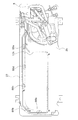
- FIG. 6 is a cross-sectional view of the electromagnetic induction heating unit.
- the electromagnetic induction heating unit 6 is arranged so as to cover the heated portion of the accumulator tube 10f from the radially outer side, and heats the heated portion by electromagnetic induction heating.
- the heated portion of the accumulator tube 10f has a double tube structure with an inner copper tube and an outer stainless steel tube 100f.
- the stainless steel material used for the stainless steel pipe 100f is a ferritic stainless steel containing 16 to 18% chromium, or a precipitation hardening system containing 3 to 5% nickel, 15 to 17.5% chromium, and 3 to 5% copper. Stainless steel is selected.
- the electromagnetic induction heating unit 6 is first positioned on the accumulator tube 10 f, then the vicinity of the upper end is fixed by the first hex nut 61, and finally the vicinity of the lower end is fixed by the second hex nut 66.
- the coil 68 is wound spirally around the outside of the bobbin main body 65 with the direction in which the accumulator tube 10f extends as the axial direction.
- the coil 68 is accommodated inside the ferrite case 71.
- the ferrite case 71 further accommodates a first ferrite part 98 and a second ferrite part 99.
- the first ferrite portion 98 is formed of ferrite having a high magnetic permeability, and collects magnetic flux generated also in portions other than the stainless steel tube 100f when a current is passed through the coil 68 to form a path for the magnetic flux.
- the first ferrite part 98 is located on both ends of the ferrite case 71.
- the second ferrite portion 99 is also different in arrangement position and shape from the first ferrite portion 98, but the function is the same as that of the first ferrite portion 98, and the position near the outside of the bobbin main body 65 in the accommodating portion of the ferrite case 71.
- the four-way switching valve 22 In the cooling operation, the four-way switching valve 22 is set to the state indicated by the dotted line in FIG.
- the compressor 21 When the compressor 21 is operated in this state, the refrigerant circuit 10 performs a vapor compression refrigeration cycle in which the outdoor heat exchanger 23 serves as a condenser and the indoor heat exchanger 41 serves as an evaporator.
- the high-pressure refrigerant discharged from the compressor 21 is condensed by exchanging heat with outdoor air in the outdoor heat exchanger 23.
- the refrigerant that has passed through the outdoor heat exchanger 23 is decompressed when passing through the expansion valve 24, and then evaporates by exchanging heat with indoor air in the indoor heat exchanger 41. Then, the indoor air whose temperature has decreased due to heat exchange with the refrigerant is blown out into the air-conditioning target space.
- the refrigerant that has passed through the indoor heat exchanger 41 is sucked into the compressor 11 and compressed. (Heating operation) In the heating operation, the four-way switching valve 22 is set to the state shown by the solid line in FIG.
- the refrigerant circuit 10 When the compressor 21 is operated in this state, the refrigerant circuit 10 performs a vapor compression refrigeration cycle in which the outdoor heat exchanger 23 serves as an evaporator and the indoor heat exchanger 41 serves as a condenser.
- the high-pressure refrigerant discharged from the compressor 21 is condensed by exchanging heat with indoor air in the indoor heat exchanger 41.
- the room air whose temperature has increased due to heat exchange with the refrigerant is blown out into the air-conditioning target space.
- the condensed refrigerant is decompressed when passing through the expansion valve 24, and then evaporates by exchanging heat with outdoor air in the outdoor heat exchanger 23.
- the refrigerant that has passed through the outdoor heat exchanger 23 is sucked into the compressor 11 and compressed.
- the electromagnetic induction heating unit 6 can heat the refrigerant to compensate for the shortage of the starting capability.
- Derosting operation When the outside air temperature is -5 ° C to 5 ° C and the heating operation is performed, moisture contained in the air condenses on the surface of the outdoor heat exchanger 23, becomes frost or freezes, and becomes an outdoor heat exchanger. Covering the surface, the heat exchange performance decreases.
- a defrosting operation is performed to melt frost or ice adhering to the outdoor heat exchanger 23. The defrosting operation is performed in the same cycle as the cooling operation.
- the high-pressure refrigerant discharged from the compressor 21 is condensed by exchanging heat with outdoor air in the outdoor heat exchanger 23.
- the frost or ice covering the outdoor heat exchanger 23 is melted by the heat radiation from the refrigerant.
- the condensed refrigerant is decompressed when passing through the expansion valve 24, and thereafter evaporates by exchanging heat with indoor air in the indoor heat exchanger 41.
- the indoor fan 42 is stopped. This is because when the indoor fan 42 is operated, the cooled air is blown into the air-conditioning target space and the comfort is impaired.
- the refrigerant that has passed through the indoor heat exchanger 41 is sucked into the compressor 11 and compressed.
- the electromagnetic induction heating unit 6 heats the accumulator tube 10f, so that the compressor 21 can compress the warmed refrigerant.
- the temperature of the gas refrigerant discharged from the compressor 21 increases, and the time necessary for melting frost is shortened. Furthermore, the return from the defrosting operation to the heating operation is accelerated.
- the high-pressure refrigerant discharged from the compressor 21 is also passed through the hot gas bypass 10h. Even when ice is growing on the bottom plate 2b of the outdoor unit 2, the ice is melted by heat radiation from the refrigerant passing through the hot gas bypass 10h. The water generated at that time is drained from the drain ports 86a to 86e. Further, since the drain ports 86a to 86e are also heated by the hot gas bypass 10h, the drain ports 86a to 86e are prevented from being blocked by freezing.
- the control unit turns on the forced stop signal for the electromagnetic induction heating unit 6. That is, when the heating operation load is small or zero, it is not necessary to assist the heating operation by the electromagnetic induction heating unit 6, and thus the heating of the refrigerant by the electromagnetic induction heating unit 6 is forcibly prohibited. For this reason, it is possible to prevent the electromagnetic induction heating unit 6 from operating wastefully and performing the heating operation.
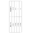
- the predetermined value can be set in four stages as shown in FIG. 7, and can be adapted to the user's preference. For example, when the user can tolerate cold or places importance on energy saving, the user can set the predetermined temperature to level 4 to set the predetermined temperature to 2K.
- the electromagnetic induction heating unit 6 When set in this way, the electromagnetic induction heating unit 6 enters a state where heating is permitted when the room temperature Tr becomes 2K lower than the room set temperature Ts. Conversely, when the user cannot tolerate the cold or places importance on comfort, the user can set the predetermined temperature to level 1 to set the predetermined temperature to -0.5K. And if it sets in this way, the electromagnetic induction heating unit 6 will be in the state in which a heating is accept
- the inverter discharge pipe temperature drooping control is performed to minimize the compressor frequency of the compressor 21 and reduce the operation capacity.
- the forced stop signal for the electromagnetic induction heating unit 6 is turned on.
- the compressor 21 can control its operating capacity by controlling the rotational frequency of an inverter (not shown). Then, when the current applied to the inverter exceeds a predetermined current value, inverter current drooping control is performed to minimize the rotation frequency of the inverter of the compressor 21 and reduce the operating capacity of the compressor 21.
- inverter current drooping control is performed, the forced stop signal for the electromagnetic induction heating unit 6 is turned on.
- the low differential pressure / Perform low compression ratio protection control when the difference between the low pressure P1 and the high pressure Ph is small and the compression ratio of the compressor 21 is small, the low differential pressure / Perform low compression ratio protection control. Specifically, when the pressure difference between the low pressure P1 and the high pressure Ph is smaller than the third pressure P3, as the low differential pressure / low compression ratio protection control, the opening of the electric expansion valve 24 is reduced, The air volume of the outdoor fan 26 is increased. When this low differential pressure / low compression ratio protection control is performed, the forced stop signal for the electromagnetic induction heating unit 6 is turned on.
- the low pressure P1 is converted based on the outdoor heat exchange temperature Tm detected by the outdoor heat exchange temperature sensor T23 in the same manner as described above.
- the high pressure Ph is detected by the discharge pressure sensor P21 in the same manner as described above.
- the inverter circuit current / temperature droop control is performed In the air conditioner 1, when the current flowing through the inverter circuit is largely outside the first predetermined range (for example, the current flowing through the inverter circuit is the first predetermined The inverter of the compressor 21 when the component temperature of the inverter circuit is high and out of the second temperature range (for example, when the component temperature of the inverter circuit is larger than the predetermined upper limit temperature). Inverter circuit current / temperature drooping control is performed to minimize the rotation frequency of the compressor 21 and reduce the operating capacity of the compressor 21. When this inverter circuit current / temperature droop control is performed, the forced stop signal for the electromagnetic induction heating unit 6 is turned on.
- total current drooping control When the total current drooping control is performed In the air conditioner 1, when the current value (total current value) applied to the entire air conditioner 1 is outside the second predetermined range (for example, the total current value is the second predetermined value). When the upper limit current value is exceeded, total current drooping control is performed to minimize the rotation frequency of the compressor 21 by the inverter and to reduce the operating capacity of the compressor 21. When this total current drooping control is performed, the forced stop signal for the electromagnetic induction heating unit 6 is turned on.
- the “total current value” referred to here is a value obtained by adding the current value applied to the compressor 21 and the current value applied to the outdoor fan 26.
- the total current value is not limited to this, and the current value applied to the indoor unit 4 and / or the electromagnetic induction heating unit is further added to the sum of the current value applied to the compressor 21 and the current value applied to the outdoor fan 26. 6 may be a sum of the current values of 6.
- the total current value is not the second predetermined upper limit current value described above, but is a third predetermined upper limit current value that is larger than the second predetermined upper limit current value.
- the compressor frequency is the lowest and the amount of refrigerant circulating through the refrigerant circuit 10 is small, the amount of refrigerant that can be heated by the electromagnetic induction heating unit 6 is reduced, and the efficiency It becomes difficult to heat the refrigerant well.
- the intake superheat calculated by subtracting the outdoor heat exchange temperature Tm detected by the outdoor heat exchange temperature sensor T23 from the intake temperature Ts detected by the inlet temperature sensor T25.
- the degree is higher than the predetermined temperature, it is determined that the refrigerant amount (filled refrigerant amount) filled in the refrigerant circuit is out of the third predetermined range (for example, the charged refrigerant amount is less than the predetermined lower limit refrigerant amount). To do.
- the air conditioning apparatus 1 when it is judged that the refrigerant
- the forced stop signal for the electromagnetic induction heating unit 6 is turned on.
- the ON prohibition setting of the electromagnetic induction heating unit 6 is performed in the initial setting.
- the user can manually cancel the ON prohibition setting of the electromagnetic induction heating unit 6.
- the user can manually set the ON prohibition setting of the electromagnetic induction heating unit 6 again when the ON prohibition setting of the electromagnetic induction heating unit 6 is released.
- the ON prohibition setting of the electromagnetic induction heating unit 6 is performed, the forced stop signal for the electromagnetic induction heating unit 6 is turned on.
- the air conditioning load is small (specifically, the difference between the indoor set temperature and the indoor temperature is a predetermined temperature).
- the refrigerant circulation amount is small (specifically, low pressure droop control, high pressure droop control, inverter discharge pipe temperature droop control, inverter current droop control) At least one of low differential pressure / low compression ratio protection control, inverter circuit current / temperature droop control, total current droop control, or a gas shortage warning state)
- the electromagnetic induction heating unit 6 is forced to stop so as not to operate.
- the electromagnetic induction heating unit 6 when the difference between the indoor set temperature and the indoor temperature is less than the predetermined temperature, the forced stop control is performed to force the electromagnetic induction heating unit 6 to be in the forced stop state.
- the present invention is not limited to this, as shown in FIG.
- thermo-on to thermo-off Even when switching from thermo-on to thermo-off and from thermo-off to thermo-on, the judgment is based on the temperature condition of the difference between the indoor set temperature and the room temperature, so the predetermined temperature for forced stop control is changed from thermo-on to thermo-off. You may link with temperature conditions and the temperature conditions from thermo-off to thermo-on.
- the present invention is useful for an air conditioner for cold regions.
- Air conditioner Outdoor unit (heat source unit) 4 Indoor units (units used) 6 Electromagnetic induction heating unit 11 Control unit 21 Compressor (compression mechanism) 22 Four-way switching valve (switching mechanism) 23 Outdoor heat exchanger (heat source side heat exchanger) 26 Outdoor fan (heat source side blower) 41 Indoor heat exchanger (use side heat exchanger) 10F accumulator pipe (refrigerant pipe)
Landscapes
- Engineering & Computer Science (AREA)
- Mechanical Engineering (AREA)
- General Engineering & Computer Science (AREA)
- Physics & Mathematics (AREA)
- Thermal Sciences (AREA)
- Chemical & Material Sciences (AREA)
- Combustion & Propulsion (AREA)
- Air Conditioning Control Device (AREA)
Abstract
Description
本発明の課題は、運転効率が低下することを防ぎ、省エネルギー化を実現する空気調和装置を提供することにある。
電磁誘導加熱ユニットは、作動させることにより例えば暖房運転の能力を補助したり、デフロスト運転のホットガスにかかる能力を補助したりしている。このような、電磁誘導加熱ユニットが、暖房運転の能力を補助する必要がない空調負荷が小さい場合に作動すると運転効率が悪くなる。また、電磁誘導加熱ユニットが、冷媒循環量が小さい状態であると、電磁誘導加熱ユニットが加熱する冷媒の量が少なくなってしまい、電磁誘導加熱ユニットの加熱にかかる効率が悪くなる。このような理由から、本発明では、電磁誘導加熱ユニットの禁止設定が手動でなされている場合、空調負荷が小さい場合、冷媒循環量が小さい状態のうちで少なくとも一つの条件が成立すると、電磁誘導加熱ユニットが作動しないように強制停止状態としている。
本発明の空気調和装置では、冷媒循環量が小さい場合として、低圧圧力が第1圧力以下となっており、低圧圧力を上げるために圧縮機構の運転容量を小さくする制限、をかけている場合がある。このような場合に、本発明では、電磁誘導加熱ユニットが作動しないように強制停止状態としている。
したがって、冷媒を加熱してもその効率が低下する場合に、電磁誘導加熱ユニットが作動することを防ぐことができる。
本発明の空気調和装置では、冷媒循環量が小さい場合として、高圧圧力が第2圧力以上となっており、高圧圧力を下げるために圧縮機構の運転容量を小さくする制限、をかけている場合がある。このような場合に、本発明では、電磁誘導加熱ユニットが作動しないように強制停止状態としている。
したがって、冷媒を加熱してもその効率が低下する場合に、電磁誘導加熱ユニットが作動することを防ぐことができる。
本発明の空気調和装置では、冷媒循環量が小さい場合として、圧縮機構の吐出側の温度が第1温度範囲から外れており、圧縮機構の吐出側の温度を第1温度範囲に収めるために圧縮機構の運転容量を小さくする制限、をかけている場合がある。このような場合に、本発明では、電磁誘導加熱ユニットが作動しないように強制停止状態としている。
したがって、冷媒を加熱してもその効率が低下する場合に、電磁誘導加熱ユニットが作動することを防ぐことができる。
したがって、冷媒を加熱してもその効率が低下する場合に、電磁誘導加熱ユニットが作動することを防ぐことができる。
したがって、冷媒を加熱してもその効率が低下する場合に、電磁誘導加熱ユニットが作動することを防ぐことができる。
したがって、冷媒を加熱してもその効率が低下する場合に、電磁誘導加熱ユニットが作動することを防ぐことができる。
したがって、冷媒を加熱してもその効率が低下する場合に、電磁誘導加熱ユニットが作動することを防ぐことができる。
したがって、冷媒を加熱してもその効率が低下する場合に、電磁誘導加熱ユニットが作動することを防ぐことができる。
したがって、冷媒を加熱してもその効率が低下する場合に、電磁誘導加熱ユニットが作動することを防ぐことができる。
本発明の空気調和装置では、冷媒量の判定を、圧縮機構の吸入過熱度が所定温度を超えているか否かにより行っている。そして、圧縮機構の吸入過熱度が所定温度を超えている場合に、冷媒量が第3所定範囲を外れていると判定しており、冷媒循環量が小さいと判定している。このような場合に、圧縮機構の吸入過熱度を所定温度以下に収めるために、圧縮機構の運転容量を小さくする制限、をかけている場合がある。このような場合に、本発明では、電磁誘導加熱ユニットが作動しないように強制停止状態としている。
したがって、冷媒を加熱してもその効率が低下する場合に、電磁誘導加熱ユニットが作動することを防ぐことができる。
第2発明から第11発明に係る空気調和装置では、冷媒を加熱してもその効率が低下する場合に、電磁誘導加熱ユニットが作動することを防ぐことができる。
<空気調和装置>
図1は、本発明の一実施形態に係る冷凍装置を用いた空気調和装置の構成図である。図1において、空気調和装置1では、熱源側ユニットとしての室外機2と、利用側ユニットとしての室内機4とが冷媒配管によって接続され、蒸気圧縮式冷凍サイクルを行う冷媒回路10が形成されている。
室外機2は、圧縮機21、四路切換弁22、室外熱交換器23、電動膨張弁24、アキュームレータ25、室外ファン26、ホットガスバイパス弁27、キャピラリーチューブ28および電磁誘導加熱ユニット6を収容している。室内機4は、室内熱交換器41および室内ファン42を収容している。
吐出管10aは、圧縮機21と四路切換弁22とを接続している。ガス管10bは、四路切換弁22と室内熱交換器41とを接続している。液管10cは、室内熱交換器41と電動膨張弁24とを接続している。室外側液管10dは、電動膨張弁24と室外熱交換器23とを接続している。室外側ガス管10eは、室外熱交換器23と四路切換弁22とを接続している。
アキューム管10fは、四路切換弁22とアキュームレータ25とを接続している。電磁誘導加熱ユニット6は、アキューム管10fの一部分に取り付けられている。アキューム管10fのうち、少なくとも電磁誘導加熱ユニット6によって覆われている被加熱部分は、銅管の周囲をステンレス鋼管が覆っている。冷媒回路10を構成する配管のうち、そのステンレス鋼管以外の部分は銅管である。
ホットガスバイパス10hは、途中にホットガスバイバス弁27が配置されている。制御部11は、ホットガスバイバス弁27を開閉して、ホットガスバイパス10hを冷媒の流通を許容する状態と許容しない状態とに切換える。また、ホットガスバイパス弁27の下流側には、冷媒の流通路の断面積を減じるキャピラリ28が設けられており、除霜運転時、室外熱交換器23を流通する冷媒とホットガスバイパス10hを流通する冷媒との割合が一定に保たれている。
四路切換弁22は、冷房運転サイクルと暖房運転サイクルとを切り替えることができる。図1では、暖房運転を行うための接続状態を実線で示し、冷房運転を行うための接続状態を点線で示している。暖房運転時、室内熱交換器41は凝縮器として、室外熱交換器23は蒸発器として機能する。冷房運転時、室外熱交換器23は凝縮器として、室内熱交換器41は蒸発器として機能する。
また、室外ユニット2および室内ユニットには、各種のセンサが設けられている。
具体的には、室外ユニット2には、圧縮機21の吐出圧力(すなわち、高圧圧力Ph)を検出する吐出圧力センサP1と、圧縮機21の吐出温度Tdを検出する吐出温度センサT21と、室外熱交換器23の液側には液状態または気液二相状態の冷媒の温度を検出する第1液側温度センサT22と、室外熱交換器23の温度(すなわち、室外熱交温度Tm)を検出する室外熱交センサT23と、アキュムレータ24の入口温度(すなわち、吸入温度Ts)を検出する入口温度センサT25とが設けられている。また、室外ユニット2の室外空気の吸入口側には、ユニット内に流入する室外空気の温度(すなわち、外気温度Ta)を検出する室外温度センサT24が設けられている。
制御部11は、室外制御部11aと室内制御部11bとを有している。室外制御部11aと室内制御部11bとは通信線11aによって接続されている。そして、室外制御部11aは室外機2内に配置される機器を制御し、室内制御部11bは室内機4内に配置されている機器を制御する。そして、制御部11は、各種センサP1、T21~T25、T41、T42の検出信号を受けることができるように接続されるとともに、これらの検出信号等に基づいて各種機器および弁6、21、22、24、26、42を制御することができるように接続されている。
図2は正面側から視た室外機の外観斜視図であり、図3は背面側から視た室外機2の外観斜視図である。図2及び図3において、室外機2の外殻は、天板2a、底板2b、フロントパネル2c、左側面パネル2d、右側面パネル2fおよび背面パネル2eによって略直方体形状に形成されている。
(室外機の内部)
図4は、右側面パネルと背面パネルを取り除いた状態を示す室外機2の斜視図である。図4において、室外機2は、仕切り板2hによって送風機室と機械室とに区分されている。送風機室には室外熱交換器23及び室外ファン26(図1参照)が配置され、機械室には電磁誘導加熱ユニット6、圧縮機21、及びアキュームレータ25が配置されている。
図5は、底板および機械室のみを残した室外機2の平面図である。なお、図5には、室外熱交換器23の位置が分かるように室内熱交換器23が2点鎖線で描かれている。ホットガスバイパス10hは底板2b上に配置されており、圧縮機21が位置する機械室側から送風機室側に延び、送風機室側を一周して機械室側に戻る。ホットガスバイパス10hの全長の約半分は、室外熱交換器23の下方にある。また、底板2bのうちの室外熱交換器23の下方に位置する部分には、底部2bを板厚方向に貫通する排水口86a~86eが形成されている。
(電磁誘導加熱ユニット)
図6は、電磁誘導加熱ユニットの断面図である。図6において、電磁誘導加熱ユニット6は、アキューム管10fのうち被加熱部分を径方向外側から覆うように配置されており、電磁誘導加熱によって被加熱部分を加熱する。アキューム管10fの被加熱部分は、内側の銅管と外側のステンレス鋼管100fとによって二重管構造となっている。ステンレス鋼管100fに使用されるステンレス材料は、クロムを16~18%含むフェライト系ステンレス、或はニッケルを3~5%、クロムを15~17.5%、銅を3~5%含む析出硬化系ステンレスが選択される。
コイル68は、ボビン本体65の外側においてアキューム管10fの延びる方向を軸方向として螺旋状に巻き付けられている。コイル68は、フェライトケース71の内側に収容されている。フェライトケース71は、第1フェライト部98及び第2フェライト部99をさらに収容している。
第1フェライト部98は、透磁率の高いフェライトによって成形されており、コイル68に電流を流した際に、ステンレス鋼管100f以外の部分にも生じる磁束を集めて磁束の通り道を形成する。第1フェライト部98は、フェライトケース71の両端側に位置する。
<空気調和装置の動作>
空気調和装置1では、四路切換弁22によって、冷房運転および暖房運転のいずれか一方に切り換えることが可能である。
(冷房運転)
冷房運転では、四路切換弁22が、図1の点線で示された状態に設定される。この状態で圧縮機21が運転されたとき、冷媒回路10では、室外熱交換器23が凝縮器となり、室内熱交換器41が蒸発器となる蒸気圧縮冷凍サイクルが行われる。
(暖房運転)
暖房運転では、四路切換弁22が、図1の実線で示された状態に設定される。この状態で圧縮機21が運転されたとき、冷媒回路10では、室外熱交換器23が蒸発器となり、室内熱交換器41が凝縮器となる蒸気圧縮冷凍サイクルが行われる。
圧縮機21から吐出された高圧の冷媒は、室内熱交換器41で室内空気と熱交換して凝縮する。そして、冷媒との熱交換によって温度上昇した室内空気は、空調対象空間に吹き出される。凝縮した冷媒は、膨張弁24を通過する際に減圧された後、室外熱交換器23で室外空気と熱交換して蒸発する。室外熱交換器23を通過した冷媒は、圧縮機11へ吸入されて圧縮される。
(除霜運転)
外気温が-5℃~5℃のときに、暖房運転がおこなわれたとき、空気中に含まれる水分が室外熱交換器23の表面で結露し、霜となり或は氷結して室外熱交換器の表面を覆い、熱交換性能が低下させる。室外熱交換器23に付着した霜、或は氷を融かすために除霜運転が行われる。除霜運転は、冷房運転と同じサイクルで行われる。
圧縮機21から吐出された高圧の冷媒は、室外熱交換器23で室外空気と熱交換して凝縮する。その冷媒からの放熱によって、室外熱交換器23を覆う霜、或は氷が融かされる。凝縮した冷媒は、膨張弁24を通過する際に減圧され、その後に室内熱交換器41で室内空気と熱交換して蒸発する。このとき、室内ファン42は停止している。なぜなら、室内ファン42が稼動すると、空調対象空間に冷やされた空気が吹き出されて快適性を損なうからである。そして、室内熱交換器41を通過した冷媒は、圧縮機11へ吸入されて圧縮される。
また、除霜運転時、ホットガスバイパス10hにも圧縮機21から吐出された高圧の冷媒が流される。室外機2の底板2b上に氷が成長している場合でも、その氷はホットガスバイパス10hを通る冷媒からの放熱によって融かされる。そのとき発生した水は、排水口86a~86eから排水される。また、排水口86a~86eもホットガスバイパス10hによって加熱されるので、排水口86a~86eが凍結によって塞がれることは防止される。
制御部11は、以下の(1)から(11)の諸条件のいずれかが成立すると、電磁誘導加熱ユニット6に対しての強制停止信号をONの状態(すなわち電磁誘導加熱ユニット6による加熱を禁止する)にさせ、その反対に以下の諸条件の全てが非成立となると、電磁誘導加熱ユニット6に対しての強制停止信号をOFFの状態(すなわち電磁誘導加熱ユニット6による加熱を許可する)にさせる(以下、この制御を強制停止制御とする)。
以下に、諸条件を説明する。
(1)室内設定温度と室内温度との差が所定温度未満である場合
リモコン等の入力手段(図示せず)により設定される室内の目標設定温度としての室内設定温度Tsから室内温度センサT42により検出される室内温度Trを差し引いた温度差ΔTrsが所定値未満であるときに、制御部は、電磁誘導加熱ユニット6に対しての強制停止信号をONの状態にする。すなわち、暖房運転負荷が小さい、あるいは、ゼロの場合に、電磁誘導加熱ユニット6による暖房運転の補助の必要がないため、強制的に電磁誘導加熱ユニット6による冷媒の加熱を禁止している。このため、無駄に電磁誘導加熱ユニット6が作動して、暖房運転を行うことを防ぐことができる。なお、所定値は、図7のように4段階に設定でき、ユーザの好みに合わせることができる。例えば、ユーザは、寒いことを許容できる、あるいは、省エネルギーを重視する場合に、所定温度の設定をレベル4に設定することにより所定温度を2Kとすることができる。このように設定されると、電磁誘導加熱ユニット6は、室内温度Trが室内設定温度Tsよりも2K低い状態になると加熱が許容される状態となる。また、逆に、ユーザは、寒いことを許容できない、あるいは、快適性を重視する場合に、所定温度の設定をレベル1に設定することにより所定温度を-0.5Kとすることができる。そして、このように設定されると、電磁誘導加熱ユニット6は、室内温度Trが室内設定温度Tsよりも0.5K高い状態になると加熱が許容される状態となる。なお、初期状態(すなわち、工場出荷時の状態)においては、所定温度の設定は、レベル3に設定されている。
圧縮機21が停止中である場合には、暖房運転中であってもサーモオフの状態であり、電磁誘導加熱ユニット6による暖房運転の補助を行う必要がない。このため、圧縮機が停止中である場合には、電磁誘導加熱ユニット6に対しての強制停止信号をONの状態にさせる。このため、無駄に電磁誘導加熱ユニット6を作動させることを防ぐことができる。
(3)低圧垂下制御を行っている場合
空気調和装置1では、低圧圧力Plが第1圧力P1以下となった場合に、圧縮機21の圧縮機周波数を最低にして運転容量を小さくする低圧垂下制御を行う。この低圧垂下制御を行っている場合に、電磁誘導加熱ユニット6に対しての強制停止信号をONの状態にさせる。なお、低圧圧力Plは、室外熱交温度センサT23により検出される室外熱交温度Tmに基づいて換算される。
空気調和装置1では、吐出圧力センサP21が検出する高圧圧力Phが第2圧力P2以上となった場合に、圧縮機21の圧縮機周波数を最低にして運転容量を小さくする高圧垂下制御を行う。この高圧垂下制御を行っている場合に、電磁誘導加熱ユニット6に対しての強制停止信号をONの状態にさせる。
(5)インバータ吐出管温度垂下制御を行っている場合
空気調和装置1では、吐出温度センサT21が検出する吐出温度Tdが第1温度範囲を外れた場合(例えば、吐出温度Tdが第1温度を超えた場合)に、圧縮機21の圧縮機周波数を最低にして運転容量を小さくするインバータ吐出管温度垂下中制御を行う。このインバータ吐出管温度垂下中制御を行っている場合に、電磁誘導加熱ユニット6に対しての強制停止信号をONの状態にさせる。
空気調和装置1では、圧縮機21はインバータ(図示せず)による回転周波数を制御することによりその運転容量の制御が可能である。そして、このインバータにかかる電流が所定電流値を超えた場合に、圧縮機21のインバータによる回転周波数を最低にして、圧縮機21の運転容量を小さくするインバータ電流垂下制御を行う。このインバータ電流垂下制御を行っている場合に、電磁誘導加熱ユニット6に対しての強制停止信号をONの状態にさせる。
(7)低差圧/低圧縮比保護制御を行っている場合
空気調和装置1では、低圧圧力Plと高圧圧力Phとの差が小さく、圧縮機21の圧縮比が小さい場合に、低差圧/低圧縮比保護制御を行う。具体的には、低圧圧力Plと高圧圧力Phとの圧力差が第3圧力P3よりも小さい場合に、低差圧/低圧縮比保護制御として、電動膨張弁24の開度を小さくして、室外ファン26の風量を大きくする。この低差圧/低圧縮比保護制御を行っている場合に、電磁誘導加熱ユニット6に対しての強制停止信号をONの状態にさせる。なお、ここで、低圧圧力Plは、上述と同様にして、室外熱交温度センサT23により検出される室外熱交温度Tmに基づいて換算される。また、高圧圧力Phは、上述と同様にして、吐出圧力センサP21により検出される。
空気調和装置1では、インバータ回路を流れる電流が大きく第1所定範囲外かられている場合(例えば、インバータ回路を流れる電流が第1所定上限電流よりも大きい場合)、または、インバータ回路の部品温度が高く第2温度範囲から外れている場合(例えば、インバータ回路の部品温度が所定上限温度よりも大きい場合)に、圧縮機21のインバータによる回転周波数を最低にして、圧縮機21の運転容量を小さくするインバータ回路電流/温度垂下制御を行う。このインバータ回路電流/温度垂下制御を行っている場合に、電磁誘導加熱ユニット6に対しての強制停止信号をONの状態にさせる。
(9)総合電流垂下制御を行っている場合
空気調和装置1では、空気調和装置1全体にかかる電流値(総合電流値)が第2所定範囲を外れる場合(例えば、総合電流値が第2所定上限電流値を超える場合)に、圧縮機21のインバータによる回転周波数を最低にして、圧縮機21の運転容量を小さくする総合電流垂下制御を行う。この総合電流垂下制御を行っている場合に、電磁誘導加熱ユニット6に対しての強制停止信号をONの状態にさせる。なお、ここにいう「総合電流値」とは、本実施形態においては、圧縮機21にかかる電流値と、室外ファン26にかかる電流値とを合算した値である。
なお、上記(3)~(9)では、圧縮機周波数が最低にしており、冷媒回路10を流れる冷媒循環量が少ない場合に、電磁誘導加熱ユニット6によって加熱できる冷媒の量が少なくなり、効率よく冷媒の加熱をすることが困難になる。したがって、電磁誘導加熱ユニット6による冷媒の無駄な加熱を、防ぐことができる。
(10)ガス欠注意報状態である場合
空気調和装置1では、入口温度センサT25が検出する吸入温度Tsから室外熱交温度センサT23が検出する室外熱交温度Tmを減ずることにより求められる吸入過熱度が所定温度よりも大きい場合に、冷媒回路に充填されている冷媒量(充填冷媒量)が第3所定範囲から外れている(例えば、充填冷媒量が所定下限冷媒量未満である)と判断する。そして、空気調和装置1では、冷媒回路に充填されている冷媒量が第3所定範囲から外れていると判断した場合に、ガス欠注意報状態となる。このガス欠注意報状態の場合に、電磁誘導加熱ユニット6に対しての強制停止信号をONの状態にさせる。
空気調和装置1では、初期設定において電磁誘導加熱ユニット6のON禁止設定が行われている。利用者は、電磁誘導加熱ユニット6を利用できるときに、電磁誘導加熱ユニット6のON禁止設定を手動で解除できる。また反対に、ユーザは、電磁誘導加熱ユニット6のON禁止設定が解除されている状態の場合に、電磁誘導加熱ユニット6のON禁止設定を再び手動で設定できる。このように、電磁誘導加熱ユニット6のON禁止設定が行われている場合に、電磁誘導加熱ユニット6に対しての強制停止信号をONの状態にさせる。
<特徴>
本実施形態に係る空気調和装置1は、電磁誘導加熱ユニット6の禁止設定が手動でなされている場合、空調負荷が小さい場合(具体的には、室内設定温度と室内温度との差が所定温度未満である場合、または、圧縮機が停止中である場合、がある)冷媒循環量が小さい状態(具体的には、低圧垂下制御、高圧垂下制御、インバータ吐出管温度垂下制御、インバータ電流垂下制御、低差圧/低圧縮比保護制御、インバータ回路電流/温度垂下制御、総合電流垂下制御のいずれかを行っている場合、または、ガス欠注意報状態である場合、がある)のうちで少なくとも一つの条件が成立すると、電磁誘導加熱ユニット6が作動しないように強制停止状態としている。
<変形例>
上記実施形態に係る空気調和装置1では、室内設定温度と室内温度との差が所定温度未満の場合に、電磁誘導加熱ユニット6を強制停止状態とする強制停止制御を行っており、この所定温度を、図7のように4段階に設定できるがこれに限らない。サーモオンからサーモオフ、および、サーモオフからサーモオンに切り換える際にも、室内設定温度と室内温度との差の温度条件により判定しているため、強制停止制御を行う際の所定温度を、サーモオンからサーモオフになる温度条件、および、サーモオフからサーモオンになる温度条件と連動させても構わない。
2 室外機(熱源ユニット)
4 室内機(利用ユニット)
6 電磁誘導加熱ユニット
11 制御部
21 圧縮機(圧縮機構)
22 四路切換弁(切換機構)
23 室外熱交換器(熱源側熱交換器)
26 室外ファン(熱源側送風機)
41 室内熱交換器(利用側熱交換器)
10F アキューム管(冷媒配管)
Claims (11)
- 運転容量が調節可能な圧縮機構(21)と、熱源側熱交換器(23)と、膨張機構(24)と、利用側熱交換器(41)とを有する冷媒回路(10)と、
冷媒配管(10f)および/または前記冷媒配管中を流れる冷媒と熱的接触をする部材を加熱する電磁誘導加熱ユニット(6)と、
前記電磁誘導加熱ユニットの動作禁止設定が手動で為されている状態、空調負荷が小さい状態、冷媒循環量が小さい状態のうちで少なくとも一つの条件を満たす場合に、前記電磁誘導加熱ユニットを強制停止状態にする制御部(11)と、
を備える空気調和装置(1)。 - 前記冷媒循環量が小さい場合は、低圧側の圧力が第1圧力以下となっており、前記圧縮機構の出力に制限をかけている場合である、
請求項1に記載の空気調和装置(1)。 - 前記冷媒循環量が小さい場合は、高圧側の圧力が第2圧力以上となっており、前記圧縮機構の出力に制限をかけている場合である、
請求項1または2に記載の空気調和装置(1)。 - 前記冷媒循環量が小さい場合は、前記圧縮機構の吐出側の温度が第1温度範囲から外れており、前記圧縮機構の出力に制限をかけている場合である、
請求項1から3のいずれかに記載の空気調和装置(1)。 - 前記圧縮機構は、動力源としてモータを有し、インバータ回路による前記モータの回転周波数制御によって、前記運転容量を調節しており、
前記冷媒循環量が小さい場合は、前記インバータ回路から前記モータの回転数を低下させることにより、前記圧縮機構の出力に制限をかけている場合である、
請求項1から4のいずれかに記載の空気調和装置(1)。 - 前記熱源側熱交換器の熱交換を促進する熱源側送風機をさらに備え、
前記冷媒循環量が小さい場合は、前記冷媒回路における高圧側の圧力と低圧側の圧力との圧力差が第3圧力よりも小さくなっており、前記熱源側送風機の出力に制限をかけている場合である、
請求項1から5のいずれかに記載の空気調和装置(1)。 - 前記冷媒循環量が小さい場合は、前記圧縮機構の電流値が第1所定範囲から外れている、または、前記インバータ回路における電機部品の温度が第2温度範囲から外れており、前記圧縮機構の出力に制限をかけている場合である、
請求項1から6のいずれかに記載の空気調和装置(1)。 - 前記熱源側熱交換器の熱交換を促進する熱源側送風機をさらに備え、
前記圧縮機構と、前記熱源側熱交換器と、前記熱源側送風機とは、熱源ユニットに含まれており、
前記冷媒循環量が小さい場合は、前記圧縮機構にかかる電流値と、前記熱源側送風機にかかる電流値と、を合算した総合電流値が第2所定範囲を外れており、前記圧縮機構の出力に制限をかけている場合である。
請求項1から7のいずれかに記載の空気調和装置(1)。 - 前記利用側熱交換器は、利用ユニットに含まれており、
前記総合電流値は、前記圧縮機構にかかる電流値と前記熱源側送風機にかかる電流値とを合算した値にさらに、前記利用ユニットにかかる電流値および/または前記電磁誘導加熱ユニットにかかる電流値を合算した値である、
請求項8に記載の空気調和装置。 - 前記冷媒循環量が小さい場合は、前記冷媒回路に充填される冷媒量が第3所定範囲から外れており、前記圧縮機構の出力に制限をかけている場合である。
請求項1から9のいずれかに記載の空気調和装置(1)。 - 前記冷媒回路に充填される冷媒量が前記第3所定範囲から外れている場合とは、前記圧縮機構の吸入過熱度が所定温度を超えている場合である、
請求項10に記載の空気調和装置。
Priority Applications (6)
| Application Number | Priority Date | Filing Date | Title |
|---|---|---|---|
| EP10753309.3A EP2410263A4 (en) | 2009-03-19 | 2010-03-19 | AIR CONDITIONING |
| AU2010225953A AU2010225953B2 (en) | 2009-03-19 | 2010-03-19 | Air conditioner |
| RU2011142178/06A RU2488047C2 (ru) | 2009-03-19 | 2010-03-19 | Кондиционер |
| JP2011504758A JP5177281B2 (ja) | 2009-03-19 | 2010-03-19 | 空気調和装置 |
| US13/203,636 US9046275B2 (en) | 2009-03-19 | 2010-03-19 | Air conditioner with electromagnetic induction heating unit |
| CN201080011822XA CN102348940B (zh) | 2009-03-19 | 2010-03-19 | 空调装置 |
Applications Claiming Priority (2)
| Application Number | Priority Date | Filing Date | Title |
|---|---|---|---|
| JP2009069101 | 2009-03-19 | ||
| JP2009-069101 | 2009-03-19 |
Publications (1)
| Publication Number | Publication Date |
|---|---|
| WO2010106814A1 true WO2010106814A1 (ja) | 2010-09-23 |
Family
ID=42739481
Family Applications (1)
| Application Number | Title | Priority Date | Filing Date |
|---|---|---|---|
| PCT/JP2010/001983 Ceased WO2010106814A1 (ja) | 2009-03-19 | 2010-03-19 | 空気調和装置 |
Country Status (8)
| Country | Link |
|---|---|
| US (1) | US9046275B2 (ja) |
| EP (1) | EP2410263A4 (ja) |
| JP (1) | JP5177281B2 (ja) |
| KR (1) | KR20110139283A (ja) |
| CN (1) | CN102348940B (ja) |
| AU (1) | AU2010225953B2 (ja) |
| RU (1) | RU2488047C2 (ja) |
| WO (1) | WO2010106814A1 (ja) |
Cited By (1)
| Publication number | Priority date | Publication date | Assignee | Title |
|---|---|---|---|---|
| JP2012247111A (ja) * | 2011-05-26 | 2012-12-13 | Mitsubishi Electric Corp | 冷凍装置 |
Families Citing this family (12)
| Publication number | Priority date | Publication date | Assignee | Title |
|---|---|---|---|---|
| CN102356283B (zh) * | 2009-03-19 | 2014-04-16 | 大金工业株式会社 | 空调装置 |
| KR20140145504A (ko) * | 2013-06-13 | 2014-12-23 | 삼성전자주식회사 | 열교환기 및 이를 포함하는 공기조화기용 실외기 |
| US10976085B2 (en) * | 2014-05-19 | 2021-04-13 | Mitsubishi Electric Corporation | Air-conditioning apparatus |
| CN105485992B (zh) * | 2016-01-06 | 2018-09-07 | 广东美的暖通设备有限公司 | 空调系统及其欠冷媒检测方法 |
| JP6671009B2 (ja) * | 2016-01-12 | 2020-03-25 | パナソニックIpマネジメント株式会社 | 空気調和装置 |
| CN106595141B (zh) * | 2016-12-12 | 2019-12-27 | 重庆美的通用制冷设备有限公司 | 一种电子膨胀阀的控制方法和装置以及制冷系统 |
| WO2019242493A1 (zh) * | 2018-06-20 | 2019-12-26 | 合肥美的暖通设备有限公司 | 热泵系统及其控制方法 |
| US11326812B2 (en) | 2018-06-20 | 2022-05-10 | Hefei Midea Heating & Ventilating Equipment Co., Ltd. | Heat pump system with electromagnetic-induction heating and control method therefor |
| JP7019070B2 (ja) * | 2018-11-14 | 2022-02-14 | 三菱電機株式会社 | 空気調和機 |
| US11728757B2 (en) | 2019-11-07 | 2023-08-15 | Carrier Corporation | System and method for controlling temperature inside electrical and electronics system |
| CN111412709A (zh) * | 2020-03-02 | 2020-07-14 | 珠海格力电器股份有限公司 | 空调器 |
| CN111473470A (zh) * | 2020-04-22 | 2020-07-31 | 四川长虹空调有限公司 | 变频制冷系统制冷剂快速泄漏的判定系统及方法 |
Citations (4)
| Publication number | Priority date | Publication date | Assignee | Title |
|---|---|---|---|---|
| JPH07301459A (ja) * | 1994-05-09 | 1995-11-14 | Kubota Corp | ヒートポンプ装置 |
| JP2000097510A (ja) | 1998-09-21 | 2000-04-04 | Sanyo Electric Co Ltd | 冷媒加熱式空気調和機 |
| JP2003269810A (ja) * | 2002-03-18 | 2003-09-25 | Denso Corp | 空気調和装置 |
| JP2007212036A (ja) * | 2006-02-08 | 2007-08-23 | Daikin Ind Ltd | 冷媒加熱装置およびその加熱容量制御方法 |
Family Cites Families (35)
| Publication number | Priority date | Publication date | Assignee | Title |
|---|---|---|---|---|
| JPS52150056U (ja) | 1976-05-10 | 1977-11-14 | ||
| JPS56148576U (ja) | 1980-04-09 | 1981-11-09 | ||
| JPS61140738A (ja) | 1984-12-12 | 1986-06-27 | Matsushita Refrig Co | 空気調和機の制御装置 |
| JPS61246537A (ja) | 1985-04-22 | 1986-11-01 | Hitachi Ltd | 空気調和機 |
| JPS6277574A (ja) | 1985-09-30 | 1987-04-09 | 株式会社東芝 | 冷凍サイクル |
| JPH01111153A (ja) | 1987-10-26 | 1989-04-27 | Matsushita Electric Ind Co Ltd | 空気調和機の制御装置 |
| JPH0338021A (ja) * | 1989-07-05 | 1991-02-19 | Canon Inc | 露光装置 |
| JPH0359358A (ja) | 1989-07-28 | 1991-03-14 | Toshiba Corp | 空気調和機 |
| JP2701516B2 (ja) | 1990-05-07 | 1998-01-21 | 松下電器産業株式会社 | 冷媒加熱装置を具備した空気調和機 |
| JP3040141B2 (ja) | 1990-07-19 | 2000-05-08 | 松下電器産業株式会社 | 空気調和機 |
| RU2027125C1 (ru) * | 1992-08-27 | 1995-01-20 | Научно-исследовательский институт энергетического машиностроения МГТУ им.Н.Э.Баумана | Парокомпрессионная холодильная установка с дроссельным регулятором расхода хладагента |
| JP2947255B1 (ja) | 1998-02-26 | 1999-09-13 | 松下電器産業株式会社 | 冷媒加熱器出口温度の制御方法 |
| JP3282719B2 (ja) | 1998-07-13 | 2002-05-20 | 船井電機株式会社 | 空気調和機の室内送風制御装置 |
| JP2000220912A (ja) | 1998-11-25 | 2000-08-08 | Daikin Ind Ltd | 冷媒加熱装置 |
| JP2001174055A (ja) | 1999-12-14 | 2001-06-29 | Daikin Ind Ltd | 誘導加熱装置 |
| JP2001255025A (ja) | 2000-03-10 | 2001-09-21 | Daikin Ind Ltd | ヒートポンプ装置 |
| JP4304832B2 (ja) | 2000-06-22 | 2009-07-29 | ダイキン工業株式会社 | 空気調和装置 |
| NO20005575D0 (no) * | 2000-09-01 | 2000-11-03 | Sinvent As | Metode og arrangement for avriming av kulde-/varmepumpeanlegg |
| JP2002106980A (ja) | 2000-09-29 | 2002-04-10 | Daikin Ind Ltd | 冷凍装置 |
| KR100382488B1 (ko) | 2000-11-10 | 2003-05-09 | 엘지전자 주식회사 | 2개의 압축기를 갖는 공조시스템의 전자팽창변 제어방법 |
| JP2003042574A (ja) | 2001-08-01 | 2003-02-13 | Denso Corp | 蒸気圧縮式冷凍機 |
| US7207379B2 (en) | 2002-03-18 | 2007-04-24 | Denso Corporation | Automotive air conditioning system |
| JP2004003827A (ja) | 2002-04-04 | 2004-01-08 | Matsushita Electric Ind Co Ltd | 冷凍サイクル装置 |
| US6868686B2 (en) | 2002-04-04 | 2005-03-22 | Matsushita Electric Industrial Co., Ltd. | Refrigeration cycle apparatus |
| JP2004003804A (ja) | 2002-04-12 | 2004-01-08 | Denso Corp | 蒸気圧縮式冷凍機 |
| US20080098760A1 (en) * | 2006-10-30 | 2008-05-01 | Electro Industries, Inc. | Heat pump system and controls |
| JP4807042B2 (ja) | 2005-11-07 | 2011-11-02 | ダイキン工業株式会社 | 冷媒加熱装置 |
| JP4033221B2 (ja) | 2005-12-02 | 2008-01-16 | ダイキン工業株式会社 | 冷媒加熱装置 |
| JP4899489B2 (ja) * | 2006-01-19 | 2012-03-21 | ダイキン工業株式会社 | 冷凍装置 |
| JP4100432B2 (ja) | 2006-02-08 | 2008-06-11 | ダイキン工業株式会社 | 冷媒加熱装置 |
| JP2007255736A (ja) | 2006-03-20 | 2007-10-04 | Daikin Ind Ltd | 冷媒加熱装置および加熱制御方法 |
| JP4815281B2 (ja) | 2006-06-26 | 2011-11-16 | 東芝キヤリア株式会社 | 空気調和機 |
| JP5324749B2 (ja) * | 2006-09-11 | 2013-10-23 | ダイキン工業株式会社 | 冷凍装置 |
| JP2008106738A (ja) * | 2006-09-29 | 2008-05-08 | Fujitsu General Ltd | ロータリ圧縮機およびヒートポンプシステム |
| JP4386071B2 (ja) | 2006-12-28 | 2009-12-16 | ダイキン工業株式会社 | 冷凍装置 |
-
2010
- 2010-03-19 EP EP10753309.3A patent/EP2410263A4/en not_active Withdrawn
- 2010-03-19 CN CN201080011822XA patent/CN102348940B/zh not_active Expired - Fee Related
- 2010-03-19 WO PCT/JP2010/001983 patent/WO2010106814A1/ja not_active Ceased
- 2010-03-19 RU RU2011142178/06A patent/RU2488047C2/ru not_active IP Right Cessation
- 2010-03-19 US US13/203,636 patent/US9046275B2/en not_active Expired - Fee Related
- 2010-03-19 AU AU2010225953A patent/AU2010225953B2/en not_active Ceased
- 2010-03-19 KR KR1020117024491A patent/KR20110139283A/ko not_active Ceased
- 2010-03-19 JP JP2011504758A patent/JP5177281B2/ja not_active Expired - Fee Related
Patent Citations (4)
| Publication number | Priority date | Publication date | Assignee | Title |
|---|---|---|---|---|
| JPH07301459A (ja) * | 1994-05-09 | 1995-11-14 | Kubota Corp | ヒートポンプ装置 |
| JP2000097510A (ja) | 1998-09-21 | 2000-04-04 | Sanyo Electric Co Ltd | 冷媒加熱式空気調和機 |
| JP2003269810A (ja) * | 2002-03-18 | 2003-09-25 | Denso Corp | 空気調和装置 |
| JP2007212036A (ja) * | 2006-02-08 | 2007-08-23 | Daikin Ind Ltd | 冷媒加熱装置およびその加熱容量制御方法 |
Non-Patent Citations (1)
| Title |
|---|
| See also references of EP2410263A4 * |
Cited By (1)
| Publication number | Priority date | Publication date | Assignee | Title |
|---|---|---|---|---|
| JP2012247111A (ja) * | 2011-05-26 | 2012-12-13 | Mitsubishi Electric Corp | 冷凍装置 |
Also Published As
| Publication number | Publication date |
|---|---|
| AU2010225953B2 (en) | 2012-11-29 |
| US20110314852A1 (en) | 2011-12-29 |
| RU2488047C2 (ru) | 2013-07-20 |
| JP5177281B2 (ja) | 2013-04-03 |
| EP2410263A1 (en) | 2012-01-25 |
| EP2410263A4 (en) | 2015-03-25 |
| CN102348940A (zh) | 2012-02-08 |
| RU2011142178A (ru) | 2013-04-27 |
| AU2010225953A1 (en) | 2011-11-03 |
| CN102348940B (zh) | 2013-07-31 |
| KR20110139283A (ko) | 2011-12-28 |
| JPWO2010106814A1 (ja) | 2012-09-20 |
| US9046275B2 (en) | 2015-06-02 |
Similar Documents
| Publication | Publication Date | Title |
|---|---|---|
| JP5177281B2 (ja) | 空気調和装置 | |
| JP5423083B2 (ja) | 空気調和装置 | |
| JP6909889B2 (ja) | 電気自動車用ヒートポンプシステム及びその制御方法 | |
| JP4666061B2 (ja) | 空気調和装置 | |
| JP5257462B2 (ja) | 空気調和装置 | |
| CN102523754A (zh) | 制冷循环装置 | |
| WO2012169182A1 (ja) | 冷凍装置 | |
| JP2013104623A (ja) | 冷凍サイクル装置およびそれを備えた空気調和機 | |
| JP5071371B2 (ja) | 空気調和装置 | |
| KR20110029447A (ko) | 공기 조화기 및 그 제어 방법 | |
| JP2010156490A (ja) | 空気調和装置 | |
| JP2007155259A (ja) | 冷媒加熱装置 | |
| JP2010223454A (ja) | 空気調和装置 | |
| JP2010127602A (ja) | 冷凍装置 | |
| JP5315990B2 (ja) | 空気調和装置およびその制御方法 | |
| CN114623508A (zh) | 空调机 | |
| JP2010112611A (ja) | 空気調和装置 | |
| JP3945523B2 (ja) | 冷凍装置 | |
| JP2013104586A (ja) | 冷凍サイクル装置およびそれを備えた空気調和機 | |
| JP2010243149A (ja) | 空気調和装置 |
Legal Events
| Date | Code | Title | Description |
|---|---|---|---|
| WWE | Wipo information: entry into national phase |
Ref document number: 201080011822.X Country of ref document: CN |
|
| 121 | Ep: the epo has been informed by wipo that ep was designated in this application |
Ref document number: 10753309 Country of ref document: EP Kind code of ref document: A1 |
|
| WWE | Wipo information: entry into national phase |
Ref document number: 13203636 Country of ref document: US |
|
| WWE | Wipo information: entry into national phase |
Ref document number: 2011504758 Country of ref document: JP |
|
| NENP | Non-entry into the national phase |
Ref country code: DE |
|
| REEP | Request for entry into the european phase |
Ref document number: 2010753309 Country of ref document: EP |
|
| WWE | Wipo information: entry into national phase |
Ref document number: 2010753309 Country of ref document: EP |
|
| ENP | Entry into the national phase |
Ref document number: 20117024491 Country of ref document: KR Kind code of ref document: A |
|
| ENP | Entry into the national phase |
Ref document number: 2011142178 Country of ref document: RU Kind code of ref document: A |
|
| ENP | Entry into the national phase |
Ref document number: 2010225953 Country of ref document: AU Date of ref document: 20100319 Kind code of ref document: A |