WO2010106902A1 - Structure de montage de porte-matrice - Google Patents
Structure de montage de porte-matrice Download PDFInfo
- Publication number
- WO2010106902A1 WO2010106902A1 PCT/JP2010/053254 JP2010053254W WO2010106902A1 WO 2010106902 A1 WO2010106902 A1 WO 2010106902A1 JP 2010053254 W JP2010053254 W JP 2010053254W WO 2010106902 A1 WO2010106902 A1 WO 2010106902A1
- Authority
- WO
- WIPO (PCT)
- Prior art keywords
- die
- die holder
- sleeve
- mounting structure
- fitting
- Prior art date
- Legal status (The legal status is an assumption and is not a legal conclusion. Google has not performed a legal analysis and makes no representation as to the accuracy of the status listed.)
- Ceased
Links
Images


Classifications
-
- B—PERFORMING OPERATIONS; TRANSPORTING
- B21—MECHANICAL METAL-WORKING WITHOUT ESSENTIALLY REMOVING MATERIAL; PUNCHING METAL
- B21D—WORKING OR PROCESSING OF SHEET METAL OR METAL TUBES, RODS OR PROFILES WITHOUT ESSENTIALLY REMOVING MATERIAL; PUNCHING METAL
- B21D37/00—Tools as parts of machines covered by this subclass
- B21D37/04—Movable or exchangeable mountings for tools
-
- B—PERFORMING OPERATIONS; TRANSPORTING
- B21—MECHANICAL METAL-WORKING WITHOUT ESSENTIALLY REMOVING MATERIAL; PUNCHING METAL
- B21D—WORKING OR PROCESSING OF SHEET METAL OR METAL TUBES, RODS OR PROFILES WITHOUT ESSENTIALLY REMOVING MATERIAL; PUNCHING METAL
- B21D28/00—Shaping by press-cutting; Perforating
- B21D28/02—Punching blanks or articles with or without obtaining scrap; Notching
- B21D28/12—Punching using rotatable carriers
-
- B—PERFORMING OPERATIONS; TRANSPORTING
- B21—MECHANICAL METAL-WORKING WITHOUT ESSENTIALLY REMOVING MATERIAL; PUNCHING METAL
- B21D—WORKING OR PROCESSING OF SHEET METAL OR METAL TUBES, RODS OR PROFILES WITHOUT ESSENTIALLY REMOVING MATERIAL; PUNCHING METAL
- B21D28/00—Shaping by press-cutting; Perforating
- B21D28/24—Perforating, i.e. punching holes
- B21D28/34—Perforating tools; Die holders
Definitions
- This invention relates to a die holder mounting structure in a punch press such as a turret punch press.
- a die holder is installed in a lower turret as a die holder support, and the die is supported by this die holder.
- Each die holder of the turret punch press can be attached with various dies with different diameters, shapes, clearances, etc.
- different types are available depending on the product to be processed. Replace the die. When replacing the die, remove the original die from the die holder and install another die.
- the lower turret diameter is made larger than the upper turret diameter, or a notch is provided in a part of the upper turret.
- the die holder is removed from the lower turret so that the die can be exchanged outside the machine.
- the configuration in which the die holder is fastened to the lower turret with a fastener such as a bolt for positioning and fixing makes it difficult to attach and detach the die from the die holder due to the space for attaching and detaching the die.
- the fixing by the fastener may cause the die holder to move in the direction along the upper surface of the lower turret due to the force in the direction perpendicular to the punching direction being applied to the die holder during punching. When the die holder moves, it needs to be returned to the original predetermined position, which requires a lot of labor and time.
- the structure in which the die holder is positioned on the lower turret by the concave and convex portions is structurally difficult to disengage the concave and convex portions, and it is not easy to remove the die holder from the lower turret at the time of die replacement.
- Still another object of the present invention is to allow the sleeve to be constrained to a fitting position where the die holder is positioned, and to switch the position of the sleeve to a non-fitting position where the die holder is not positioned if necessary. It is. Still another object of the present invention is to smoothly switch the position between the fitting position and the non-fitting position of the sleeve.
- the die holder mounting structure of the present invention is a mounting structure for mounting a die holder for holding a die on an upper surface of a die holder support on which the die holder is slidably mounted, and is provided with a sleeve fitting recess on the upper surface of the die holder support,
- the die holder can be switched between a fitting position for fitting into the sleeve fitting recess and a non-fitting position where the lower end of the die holder is removed from the sleeve fitting recess and is the same height as or higher than the upper surface of the die holder support.
- a sleeve was provided.
- the slide of the die holder along the upper surface of the die holder support is restrained, and the die holder is positioned at a predetermined position.
- the sleeve In a state where the sleeve is in a non-fitting position that is out of the sleeve fitting recess, the sleeve can be slid along the upper surface of the die holder support. Therefore, the die holder can be positioned relative to the die holder support and released by simply switching the position of the sleeve between the fitting position and the non-fitting position.
- the die holder can be easily positioned and attached to and removed from the die holder support, and the structure can be simplified.
- the slide of the die holder is restrained by fitting the sleeve into the sleeve fitting recess, positioning in the direction along the upper surface of the die holder support can be restrained with high accuracy.
- the use of the sleeve makes it possible to position the die holder without moving it in the direction perpendicular to the upper surface of the die holder support, making it easy to attach and detach the die holder and the upper turret.
- the die holder can be attached and detached. Therefore, unlike the prior art, it is not necessary to make the lower turret diameter larger than the upper turret diameter or to provide a notch in a part of the upper turret.
- the die holder has a die holding recess for holding the die and a sleeve insertion hole extending downward following the bottom surface of the die holding recess, and the sleeve fits in the sleeve insertion hole. It is preferable that the position is switched between the mating position and the non-fitting position, and the upper end is higher than the bottom surface of the die holding recess in the non-fitting position.
- the sleeve when the sleeve is brought into the non-fitting position, the upper end of the sleeve is positioned higher than the bottom surface of the die holding recess of the die holder, and the die held in the die holding recess is pushed up by the sleeve. Therefore, when the positioning of the die holder with respect to the die holder support is released with the sleeve in the non-fitting position, the die is removed from the die holding recess at the same time, so that the die can be easily attached to and detached from the die holder.
- a biasing means for constantly biasing the sleeve toward the non-fitting position. If the urging means is provided, the position of the sleeve can be switched from the fitting position to the non-fitting position without applying an external force. For this reason, without providing a special mechanism, the sleeve can be easily pulled out from the sleeve fitting recess of the die holder support while the die holder is attached to the die holder support.
- the urging means applies a urging force to the outer peripheral portion of the sleeve, and it is preferable that a plurality of urging means be provided on the outer periphery of the sleeve.
- a plurality of biasing means By providing a plurality of biasing means on the outer periphery of the sleeve for applying a biasing force to the outer peripheral portion of the sleeve, a substantially uniform biasing force is applied to the sleeve in the circumferential direction. The position can be switched smoothly with the non-fitting position.
- the biasing means is for a slider that engages with an engagement hole formed in the peripheral wall of the sleeve, and a biasing means that biases the slider toward the non-fitting position. It is preferable to have a spring member. According to this configuration, the biasing means can have a simple structure.
- a restraining means for restraining the sleeve at the fitting position against the biasing force of the biasing means, and a manually operated operation tool for releasing the function of the restraining means are provided. Is good.
- the restraining means By providing the restraining means, the sleeve can be restrained at the fitting position in a state where the die holder is attached to a normal die holder support. Further, by providing the operation tool, the function of the restraining means is canceled and the sleeve can be switched to the non-fitting position as necessary when the die is replaced.
- the restraining means When the restraining means and the operation tool are provided, the restraining means includes a lock pin extending in a substantially horizontal direction in which a tip portion can be freely engaged with and disengaged from a lock hole formed in the sleeve, and biasing the lock pin toward the sleeve. And the operating tool extends in a substantially vertical direction, and when the lowering operation is performed, the operating pin is pushed in a direction in which the locking pin is retracted to disengage the tip portion from the locking hole. Is preferred. According to this configuration, the restraining means can have a simple structure.
- the die holder has a die holder main body having a die holding recess capable of holding a die, and a die clamper for fixing the die in the die holding recess, and the die clamper holds the lock pin from above.
- the covering structure is preferable. According to this configuration, it is possible to prevent dust and foreign matter from adhering to the lock pin.
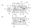
- FIG. 3A is a cross-sectional view of a die holder and a lower turret shown in section III-III in FIG.
- FIG. 2A, and FIG. 3B is a view showing different states thereof. It is the fragmentary top view which abbreviate
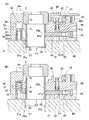
- (A) and (B) are VV sectional views of FIG. In the VI-O-VI cross-sectional view of FIG. 4, (A) and (B) show different states.
- (A) is the perspective view which looked at the die clamper of the die holder from diagonally upward
- (B) is the perspective view which looked from diagonally below.
- (A) is a perspective view of the lock pin of the die holder, and (B) is a perspective view of the operation pin.
- (A) is a side view of a fixing pin of the die holder, and (B) is a bottom view thereof.
- (A) is a side view of the cam bush of the same die holder, and (B) is a bottom view thereof.
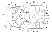
- the die holder mounting structure of this embodiment is applied to a turret punch press.
- the turret punch press has an upper turret 1 and a lower turret 2, and the punch holder 4 can be raised and lowered within a plurality of punch fitting holes 3 arranged in the circumferential direction of the upper turret 1. Is fitted.
- the punch holder 4 is, for example, a forcible pull-up type having a built-in punch (not shown), and has a head 4a having a T-shaped cross section that engages with a ram and a guide plate (not shown).
- the die holder 6 that holds the die 5 is installed on the lower turret 2 that serves as a die holder support.
- the die holder 6 has, for example, a substantially fan shape in plan view, and a die holding recess 7 (center O (FIG. 4)) for fitting the die 5 is provided in the approximate center of the upper surface. It has been.
- the die holding recess 7 has a circular shape having a center O shown in FIG. 4, and the sleeve insertion hole 8 shown in FIGS. 3A and 3B, which also serves as a slag discharge, extends downward.
- the die 5 is held in a state where the die 5 is fitted on the die holding recess 7 and is placed on the bottom surface 7 a that forms a step with the sleeve insertion hole 8.
- the die 5 in the die holding recess 7 is fixed by the clamp mechanism 10.
- the clamp mechanism 10 includes a die clamper 11 (see FIG. 7) that constitutes an outer diameter side portion of the upper portion of the die holder 6 at a normal time.
- the upper portion of the die holder 6 is an intermediate portion in the turret radial direction and is divided into an upper portion of the die holder body 6a and the die clamper 11.
- the die clamper 11 is made of a member different from the die holder main body 6a, revolves around a revolving shaft 12 located on the outer diameter side of the turret of the die holding recess 7, and a die pressing position Q1 indicated by a solid line in FIG. The position can be switched to a die release position Q2 indicated by a two-dot chain line.
- the upper surface of the die holder body 6a and the upper surface of the die clamper 11 are the same height.
- the turning shaft 12 is composed of a pair of individual turning shafts 12 a disposed on both sides of the center line CL in plan view of the die holder 6, and formed on the bottom surface of the die clamper 11 on these individual turning shafts 12 a.
- the groove-shaped turning guide part 13 (FIG. 3A) thus engaged is rotatably engaged.
- Each individual turning shaft 12 a is supported by each turning shaft support block 14.
- Each individual turning shaft 12 a may be provided integrally with each turning shaft support block 14.
- the turning shaft support block 14 has an advance / retreat guide shaft 15 shown in FIG. 5 (A) protruding in parallel with the center line CL toward the inner side of the turret.
- the reciprocating guide hole 17 is slidably fitted, and between the large diameter portion 15a and the convex portion 16 at the tip thereof, a turning shaft spring member 18 urged toward the large diameter portion 15a is interposed. It is.
- the pivot shaft spring member 18 is, for example, a disc spring.
- the turning shaft support block 14 is in contact with the surface of the convex portion 16 on the turret outer diameter side when no external force is applied, and resists the force of the turning shaft spring member 18 when the external force in the turret outer diameter direction is applied. Then retreat to the outer diameter side of the turret. That is, the turning shaft 12 is movable in a direction approaching and separating from the die 5. Since the turning guide portion 13 has a groove shape with an opening at the bottom, when the die clamper 11 is in the die release position Q2, the turning guide portion 13 and the turning shaft 12 are disengaged, and the die clamper 11 is removed from the die holder body 6a. Can be removed.
- the end surface 20 of the die clamper 11 on the inner side of the turret has a semicircular planar shape, and the end surface 20 is in the die holding recess when the die clamper 11 is at the die pressing position Q1 in FIG. 7 is fitted to the outer periphery of the die 5 in the state 7 in contact with at least a part thereof.
- the turret inner diameter side portion of the die clamper 11 is provided with a hanging portion 21 that hangs downward at two locations across the center line CL. The vertical dimension is longer than the others.
- a protruding die contact portion 22 is formed at the lower end of the drooping portion 21 on the inner side of the turret and protrudes by a small amount toward the inner side of the turret.
- the die contact portion 22 is formed, for example, in a curved surface having an arc shape in a vertical section.
- the die contact part 22 may be partially formed.
- the die contact portion 22 is located below the center of the turning shaft 12. 5A and 5B, the height of the turning shaft 12 is indicated by H.
- the die contact portion 22 presses the side surface on the turret outer diameter side of the die 5 held in the die holding recess 7 (FIG. 4).
- the turret inner diameter side surface of the die 5 is pressed against the inner surface of the die holding recess 7.
- the die 5 is fixed in the die holding recess 7. Since the die contact portion 22 is positioned below the pivot shaft 12 in a state where the die clamper 11 is at the die pressing position Q1, the die clamper 11 is moved to the die pressing position Q1 from the die release position Q2.
- a downward force is applied to the die 5, and the die 5 is securely seated so as to contact the bottom surface of the die holding recess 7.
- the die contact portion 22 passes through a predetermined halfway position Q3 shown in FIG.
- the horizontal distance between the pivot shaft 12 and the portion where the die contact portion 22 of the die 5 contacts is the longest. Since the swivel shaft 12 can move in a direction approaching and moving away from the die 5, when the die clamper 11 is at a predetermined midway position Q3, the swivel shaft 12 is retracted in a direction away from the die 5 and in a predetermined midway.
- the turning shaft 12 can be advanced in the direction approaching the die 5, and the die clamper 11 can be turned without difficulty.
- the turning shaft 12 is biased in the direction approaching the die 5 by the turning shaft spring member 18, even if the turning shaft 12 is at the die pressing position Q1 located below the predetermined midway position Q3, The die contact portion 22 can press the die 5 with an appropriate pressing force.
- a sleeve fitting recess 25 is provided on the upper surface of the lower turret 2 at the same position as the sleeve insertion hole 8 in plan view.
- a sleeve 26 on which the die 5 is placed is slidably inserted. This sleeve 26 is fitted to the sleeve fitting recess 25, and the lower end of the sleeve 26 is removed from the sleeve fitting recess 25, and the lower end is the same as or higher than the upper surface of the lower turret 2 as a die holder support.
- the position can be switched to a non-fitting position P2 shown in FIG.
- the upper end of the sleeve 26 is at a position higher than the bottom surface 7a of the die holding recess 7.
- a slag discharge hole 27 is provided following the bottom surface 25a of the sleeve fitting recess 25, and the sleeve fitting recess 25 and the slag discharge hole 27 constitute a through-hole penetrating the lower turret 2 up and down.
- the slag discharge hole 27 has a diameter smaller than that of the sleeve fitting recess 25, and a step portion is formed on the bottom surface 25 a of the sleeve fitting recess 25.
- the outer periphery of the lower end of the sleeve 26 is chamfered.
- the die holder body 6a is provided with a biasing means 30 that biases the sleeve 26 toward the non-fitting position P2.
- the biasing means 30 includes a slider 31, a pressing member 32, and a biasing means spring member 33.
- the slider 31 has a cylindrical shape having an end wall at the upper end, is slidable along a vertical guide hole 34 provided in the die holder 6, and has an engagement piece 31 a protruding from the lower end toward the center of the sleeve insertion hole 8.
- the sleeve 26 is engaged with an engagement hole 26 a formed on the outer peripheral surface of the peripheral wall of the sleeve 26.
- the engagement piece 31a is inserted through a vertically long slit 35 that allows the vertical guide hole 34 and the sleeve insertion hole 8 to communicate with each other.
- the pressing member 32 includes a plate portion 32a fixed with a bolt (not shown) to the bottom surface of a recess (not shown) provided on the lower surface of the die holder body 6a, and a rod-like portion 32b protruding upward from the plate portion 32a. And become.
- the rod-shaped part 32 b is inserted into the hollow part of the slider 31.
- the biasing means spring member 33 is, for example, a compression coil spring, and is provided between the inner periphery of the slider 31 and the rod-like portion 32b of the pressing member 32.
- the upper end is in contact with the upper end wall of the slider 31, and the lower end is the pressing member. It is in contact with 32 plate portions 32a.
- a plurality of sets of biasing means 30 configured as described above are provided on the outer periphery of the sleeve 26 in a substantially uniform arrangement in the circumferential direction, for example, four sets in this embodiment.
- a restraining means 40 for restraining the sleeve 26 to the fitting position P1 against the biasing force of the biasing means 30 is provided.
- the restraining means 40 is provided with a lock pin 41 (see FIG. 8A) extending in a substantially horizontal direction in which a tip end portion 41a made of a protrusion can be engaged with and disengaged from a lock hole 26b formed through the peripheral wall of the sleeve 26.
- the lock pin 41 is urged toward the sleeve 26 by the lock spring member 42.
- the locking spring member 42 is, for example, a compression coil spring.
- the tip 41a of the lock pin 41 biased by the locking spring member 42 engages with the lock hole 26b of the sleeve 26, and the sleeve 26 is brought into the fitting position P1. to bound.
- the lock pin 41 and the lock spring member 42 are inserted into a lock pin insertion hole 43 provided in the die holder 6, and a screw-type plug member 44 is attached to the open end of the lock pin insertion hole 43, whereby the lock pin 41 Further, the locking spring member 42 is prevented from coming off.
- the lock pin insertion hole 43 is provided obliquely with respect to the center line CL of the die holder 6 shown in FIG. 4 in order to avoid interference with a fixing pin insertion hole 78 shown in FIG.
- the lock pin insertion hole 43 may be provided in parallel with the center line CL.
- a manually operated operation tool 45 for releasing the function of the restraining means 40 in FIG. 6A is provided.
- the operation tool 45 includes an operation pin 46 extending substantially in the vertical direction, a lift pin 47 and a lift return spring 48, and the lock pin 41.
- the operation pin 46 includes an upper cylindrical portion 46a having a lift pin hole 49 penetrating vertically, and a U-shaped bifurcated open to the lower end connected to the lower end of the cylindrical portion 46a.
- the end surface of the forked portion 46b opposite to the sleeve insertion hole 8 is an inclined surface 50 that approaches the sleeve insertion hole 8 side as it goes downward. As shown in FIG.
- the lock pin 41 is composed of a columnar portion 41b near the base end and a plate-like portion 41c having a vertically long cross section from the intermediate portion to the distal end, and both portions 41b and 41c.
- the step surface is an inclined surface 51 corresponding to the inclined surface 50.
- the bifurcated portion 46b of the operation pin 46 straddles the plate-like portion 41c of the lock pin 41, and the inclined surfaces 50 and 51 of the operation pin 46 and the lock pin 41 are in contact with each other.
- the lift pin 47 of FIG. 6A is installed on the plate-like portion 41 c (FIG. 8A) of the lock pin 41, and the upper portion is inserted into the lift pin hole 49.
- the lift return spring 48 is provided on the outer periphery of the lift pin 47, and both ends thereof are in contact with the large diameter portion 47 a of the lift pin 47 and the step surface 49 a of the lift pin hole 49.
- the upper surface of the die holder 6 serves as a table auxiliary for placing and guiding a workpiece, and a conveying ball 53 is provided on the inner side of the turret of the die holding recess 7 and a brush 54 is provided on the outer side. It has been.
- the conveying ball 53 is rotatably supported by a bearing case 55, and the bearing case 55 is provided in an embedded state in the die holder body 6a.
- the brush 54 is attached to the die clamper 11.
- the die holder 6 is locked by the die holder locking mechanism 60 at the inner end in the turret radial direction with respect to the lower turret 2 that is a die holder support, and at a position on the outer side of the turret than the die holding recess 7.
- the die holder fixing mechanism 70 is fixed in a state of preventing the floating.
- the die holder locking mechanism 60 and the die holder fixing mechanism 70 will be described in detail.
- the die holder locking mechanism 60 locks the inner end of the die holder 6 using a locking pin 61 with a head.
- An inner end engaging piece 62 protrudes from the end surface of the die holder 6 on the inner side of the turret, and an engagement notch 63 (FIG. 2A) having a substantially U-shape in a planar shape is provided at the tip.
- the engagement notch 63 is open at the opening side in a tapered shape.
- the engagement notch 63 is fitted to the shaft portion of the locking pin 61, and the head 61 a having an enlarged diameter of the locking pin 61 is engaged with the upper surface of the inner end engagement piece 62.
- the head 61a may be omitted.
- the tip of the shaft portion of the locking pin 61 is formed on the male screw 61 b and is screwed into the screw hole 64 of the lower turret 2.
- the locking pin 61 and the lower turret 2 may be coupled by an interference fit instead of screwing.
- the die holder fixing mechanism 70 has a fixing pin 71 that is manually rotated. As shown in FIGS. 9A and 9B, the fixing pin 71 is provided with a spiral cam groove 72 on the lower outer peripheral surface. The upper end of the cam groove 72 is a horizontal groove 72a along the circumferential direction. The lower end portion of the cam groove 72 communicates with the lower end surface of the fixing pin 71 through the vertical groove 73.
- An annular groove 74 for locking the ball plunger 96 (FIG. 4) is provided on the outer peripheral surface above the cam groove 72, and a retaining ring 81 (FIG. 3A) is mounted on the outer peripheral surface above the cam groove 72.
- An annular groove 75 is provided.
- the upper end of the fixing pin 71 is a head 71a having a larger diameter than the others, and a tool insertion hole 76 including a hexagonal hole for inserting a turning tool such as a hexagon wrench is provided on the end surface of the head 71a. It has been.
- a mark groove 77 is provided at one place on the peripheral surface of the head 71a so that the circumferential phase of the fixing pin 71 can be viewed from above.
- the fixing pin 71 is inserted through a fixing pin insertion hole 78 provided in the die holder main body 6a of FIG.
- the fixing pin insertion hole 78 has a reduced diameter portion 78a at the upper and lower intermediate portions, and the upper and lower intermediate portions of the fixing pin 71 are slidably fitted into the reduced diameter portion 78a.
- 71a is located above the reduced diameter portion 78a.
- a disc spring 79 and a spacer 80 are interposed between the head 71a and the upper step surface F of the reduced diameter portion 78a.
- disc springs 79 and spacers 80 are fixed pins 71 in a state where the upper step surface F is not supported by a retaining ring 81 attached to the annular groove 75 (FIG. 9A) (FIG. 3B). In addition, it is held in a fall regulated state.
- the lower turret 2 is provided with a large concave portion 82 that opens upward and a small concave portion 83 that extends downward from the bottom of the large concave portion 82, and a cam bush 84 is fitted into the concave portions 82 and 83. ing. As shown in FIGS. 10A and 10B, the cam bush 84 protrudes downward from the main body portion 84a located in the large recessed portion 82 (FIG. 3A) and the lower end of the main body portion 84a. Thus, there is provided a fixing pin insertion hole 85 that vertically penetrates from the main body portion 84a to the convex portion 84b. The convex portion 84b is fitted with the small concave portion 83 (FIG.
- a key 86 is attached to the cam bush 84 at a predetermined height in the fixing pin insertion hole 85 so as to project radially inward.
- the key 86 has a rivet shape including a cylindrical shaft portion 86a and a head portion 86b, and is attached to the key mounting hole 87 by, for example, an interference fit, and the tip of the shaft portion 86a is attached to a fixing pin insertion hole. 85 is projected.
- the key attachment hole 87 is provided in the horizontal direction from the vertical groove 88 formed on the outer periphery of the main body portion 84 a of the cam bush 84 toward the fixing pin insertion hole 85. In a state where the key 86 is attached, the head portion 86 b of the key 86 is located in the vertical groove 88.
- the cam bush 84 is a die holder support body by screwing a fixing bolt 90 that passes through the lower turret 2 from the lower surface of the lower turret 2 in FIG. 3A into the screw hole 91 of the cam bush 84. Fixed to the turret 2. In this state, the die holder side fixing pin insertion hole 78 and the support side fixing pin insertion hole 85 are aligned in the horizontal direction. Therefore, the lower part of the fixing pin 71 inserted into the die holder side fixing pin insertion hole 78 can be inserted into the support side fixing pin insertion hole 85.
- the fixing pin urging means 92 is made of, for example, a compression coil spring, and includes an upper support member 93 slidably fitted into the support-side fixing pin insertion hole 85 and a lower support member 94 provided at the bottom of the small recess 83. Between.
- the upper support member 93 stores the upper portion of the fixed pin urging means 92 in the recess 93a that opens downward, thereby holding the upper portion of the fixed pin urging means 92 so as not to be displaced in the horizontal direction.
- the upper end surface of the upper support member 93 is in contact with the bottom surface of the fixing pin 71.
- the upper part of the upper support member 93 is reduced in diameter compared to the lower part in order to avoid interference with the key 86.
- the lower support member 94 holds the lower portion of the fixed pin urging means 92 so as not to be displaced in the horizontal direction by inserting the shaft core portion 94a protruding upward into the lower portion of the fixed pin urging means 92.
- a screw hole 95 penetrating from the side surface of the die holder body 6 a to the peripheral surface of the reduced diameter portion 78 a of the die holder side fixing pin insertion hole 78 is provided.
- a ball plunger 96 is screwed into the annular groove 74 so as to detachably press the ball at the tip thereof.
- the die holder 6 of FIG. 3 (A) When attaching the die holder 6 of FIG. 3 (A) to the lower turret 2, first, the inner end portion of the die holder 6 on which the die 5 is placed with respect to the lower turret 2 which is a die holder support is set to the die holder. Locking is performed by the locking mechanism 60. In this state, the die holder 6 can turn around the locking pin 61 along the upper surface of the lower turret 2 and can slide along the longitudinal direction of the engagement notch 63.
- the sleeve 26 is positioned just above the fitting recess 25 of the lower turret 2 while turning and sliding, and the die 5 is manually pushed downward to make the sleeve 26 is inserted into the fitting recess 25.
- the die holder 6 is positioned with respect to the lower turret 2.
- the die holder side fixing pin insertion hole 78 matches the support side fixing pin insertion hole 85.
- the fixing pin 71 is inserted into the die holder side fixing pin insertion hole 78 from above.
- the fixing pin 71 may be inserted into the die holder side fixing pin insertion hole 78 in advance.
- the circumferential direction phase of the fixing pin 71 is adjusted by directing the mark groove 77 (FIG. 9B) provided in the head 71 a of the fixing pin 71 in a predetermined circumferential direction.
- the die holder fixing mechanism 70 is in the state shown in FIG. That is, the bottom surface of the fixing pin 71 contacts the upper end surface of the upper support member 93, and the key 86 is positioned immediately below the vertical groove 73 (FIG. 9B) of the fixing pin 71.
- a tool for turning operation such as a hexagon wrench is inserted into the tool insertion hole 76 of the fixing pin 71, the fixing pin 71 is pushed down a little, and then the fixing pin 71 is moved in a predetermined direction using the tool. turn.
- the key 86 relatively moves from the longitudinal groove 73 of the fixing pin 71 into the spiral cam groove 72 and moves from the lower end to the upper end of the cam groove 72. Accordingly, the fixing pin 71 is displaced downward against the urging force of the fixing pin urging means 92. Since the upper end of the cam groove 72 is a horizontal groove 72a (FIGS.
- the key 86 is stably held by the horizontal groove 72a, and the fixing pin 71 is also stable at this position.
- the state of the die holder fixing mechanism 70 at this time is the pressing and fixing state of FIG.
- the head 71 a of the fixing pin 71 presses the upper step surface F of the die holder 6 via the disc spring 79 and the spacer 80, thereby preventing the die holder 6 from being lifted with respect to the lower turret 2. Fix to state.
- the fixing pin 71 can be easily removed from the die holder side fixing pin insertion hole 78. If the ball plunger 96 is advanced and engaged with the annular groove 74 of the fixing pin 71 in this state, the fixing pin 71 can be stably held at the height of FIG.
- the die holder fixing mechanism 70 is configured as described above, and can be rephrased as follows. That is, the die holder fixing mechanism 70 is provided with a die holder side fixing pin insertion hole 78 in the die holder 6 that holds the die 5, and a support side fixing pin insertion hole in the die holder support (lower turret) 2 that supports the die holder 6.
- 85 is a die holder fixing mechanism in which the fixing pin 71 is inserted in a state where both the fixing pin insertion holes 78 and 85 are aligned in the horizontal direction, and the die holder 6 is pressed and fixed to the die holder support 2 by the fixing pin 71.
- the fixing pin 71 is rotatable about the pin axis so that the die holder 6 can be switched between a pressing and fixing state with respect to the die holder support 2 and a release state thereof.
- a fixing pin urging means 92 is provided below the support-side fixing pin insertion hole 85 to urge the fixing pin 71 upward in the pressed and fixed state. Is configured to lift the fixing pin 71 becomes the release state.
- the die holder fixing mechanism 70 of this embodiment is a combination of a helical cam groove 72 provided in the fixing pin 71 of FIG. 3A and a key 86 that engages with the cam groove 72.
- the die holder 6 is fixed to the lower turret 2 as a die holder support, but the die holder 6 may be fixed to the lower turret 2 with a general bolt without using the fixing pin 71.
- the die replacement work in the die holder mounting structure having the above configuration will be described.
- the die clamper 11 is turned to the die release position Q2 shown in FIG.
- dye contact part 22 of the die clamper 11 is lose
- the die clamper 11 is removed from the die holder main body 6a, a space can be opened around the die holding recess 7, so that the subsequent die replacement operation can be easily performed.
- the die 5 in the die holding recess 7 is pushed up by the sleeve 26 whose position has been switched to the non-fitting position P2. Therefore, the die 5 can be easily taken out by hand without inserting a hand or tools into the inside of the die holder 6 or below the lower turret 2.
- the operation pin 46 is returned to the pushed-up state by the action of the rising return spring 48. In this state, the tip convex portion 41 a of the lock pin 41 pushed by the lock spring member 42 is in contact with the outer peripheral surface located immediately below the lock hole 26 b of the sleeve 26.
- the die 5 When a new die 5 is mounted, the die 5 is placed on the sleeve 26 at the non-fitting position P2, and the die 5 is manually pushed downward to come into contact with the bottom surface 7a of the die holding recess 7. Accordingly, the sleeve 26 is pushed down to the fitting position P1 in FIG. Then, the tip end portion 41a of the lock pin 41 is engaged with the lock hole 26b of the sleeve 26, and the sleeve 26 is restrained at the fitting position P1.
- the die clamper 11 When the die clamper 11 is removed, the die clamper 11 is mounted on the die holder main body 6a, and then the die clamper 11 is turned to the die pressing position Q1 (FIG. 5A).
- the die clamper 11 applies a downward force to the die 5 during the turning process, the die 5 can be surely seated so as to be in contact with the bottom surface 7 a of the die holding recess 7.
- the die contact portion 22 of the die clamper 11 shown in FIG. To press the turret inner diameter side surface of the die 5 against the inner surface of the die holding recess 7. Thereby, the die 5 is fixed in the die holding recess 7.
- the die 5 may be exchanged outside the machine with respect to the die holder 6 removed from the lower turret 2.
- the fixing by the die holder fixing mechanism 70 and the locking by the die holder locking mechanism 60 in FIG. Remove from turret 2.
- the sleeve 26 is in the non-fitting position P ⁇ b> 2 in FIG. 3B, and its lower end is removed from the sleeve fitting recess 25 of the lower turret 2, so that the die holder 6 is moved along the upper surface of the lower turret 2. Can be moved freely. Therefore, the attaching / detaching work of the die holder 6 with respect to the lower turret 2 is easy.
- the die clamper 11 in FIG. 5A also serves as a cover for the die holder main body 6a, and the operation pins 46 and the fixing pins in FIG. 6A provided on the die holder main body 6a in a state where the die clamper 11 is in the die pressing position Q1. Since 71 is covered from above, it can prevent that dust and a foreign material adhere to them. Further, as shown in FIG. 2B, since the upper surface of the die clamper 11 is the same height as the upper surface of the portion of the die holder body 6a not covered with the die clamper 11, the die clamper 11 is used as a table support for workpiece conveyance. Available. Specifically, the work is conveyed by being guided by a conveying ball 53 provided on the die holder main body 6a and a brush 54 provided on the die clamper 11.
- the die holder 6 can be attached to the lower turret 2 as a die holder support only by switching the position of the sleeve 26 shown in FIGS. 3A and 3B between the fitting position P1 and the non-fitting position P2. Positioning and release can be performed. Since fasteners such as bolts are not used, the die holder can be easily attached to and detached from the lower turret 2 and the structure can be simplified. Since the sleeve 26 having a diameter larger than that of the fixing pin 71 is fitted into the sleeve fitting recess 8 to restrain the slide of the die holder 6, the positioning accuracy in the direction along the upper surface of the lower turret 2 is high.
- the sleeve 26 When the sleeve 26 is set to the non-fitting position P ⁇ b> 2, the upper end of the sleeve 26 is higher than the bottom surface 7 a of the die holding recess 7 of the die holder 6, and the die 5 held in the die holding recess 7 is pushed up by the sleeve 26. Therefore, the die 5 can be easily attached to and detached from the die holder 6. Since the urging means 30 (FIG. 6 (A)) for constantly urging the sleeve 26 toward the non-fitting position P2 is provided, the sleeve 26 is not fitted from the fitting position P1 without applying external force. The position can be switched to the position P2, and the work can be simplified.
- the die holder 6 can be positioned without moving in the direction orthogonal to the upper surface of the lower turret 2 in FIG. 1 that is the die holder support, the lower turret 2 even when the lower surface of the upper turret 1 and the upper surface of the die 5 are narrow.
- the die holder 6 can be attached and detached. Further, by removing the die clamper 11 shown in FIGS. 3A and 3B from the die holder main body 6a, a space can be opened around the die holding recess 7 so that the die 5 can be easily attached to and detached from the die holder 6. Yes.
Landscapes
- Engineering & Computer Science (AREA)
- Mechanical Engineering (AREA)
- Mounting, Exchange, And Manufacturing Of Dies (AREA)
- Punching Or Piercing (AREA)
Abstract
L'invention porte sur une structure de montage de porte-matrice dans laquelle on peut exécuter le positionnement d'un support de porte-matrice dans la direction de la surface de support de porte-matrice avec une grande précision sans utiliser un outil de fixation, tel qu'un boulon. Le porte-matrice (6) maintenant une matrice (5) est monté sur la surface supérieure d'un support de porte-matrice (2) sur lequel le porte-matrice (6) est placé de manière coulissante. Le support de porte-matrice (2) est disposé, sur sa surface supérieure, avec un évidement d'ajustement de manchon (25). Le porte-matrice (6) est muni d'un manchon (26) mobile destiné à passer d'une position de prise (P1) dans laquelle le manchon est ajusté dans l'évidement d'ajustement de manchon (25) à une position de libération (P2) dans laquelle le manchon est libéré de l'évidement d'ajustement de manchon (25) et l'extrémité inférieure du manchon (26) est alignée avec la surface supérieure du support de porte-matrice (2) ou placée dans une position plus haute que celle-ci.
Applications Claiming Priority (2)
| Application Number | Priority Date | Filing Date | Title |
|---|---|---|---|
| JP2009067392A JP5428430B2 (ja) | 2009-03-19 | 2009-03-19 | ダイホルダ取付構造 |
| JP2009-067392 | 2009-03-19 |
Publications (1)
| Publication Number | Publication Date |
|---|---|
| WO2010106902A1 true WO2010106902A1 (fr) | 2010-09-23 |
Family
ID=42739566
Family Applications (1)
| Application Number | Title | Priority Date | Filing Date |
|---|---|---|---|
| PCT/JP2010/053254 Ceased WO2010106902A1 (fr) | 2009-03-19 | 2010-03-01 | Structure de montage de porte-matrice |
Country Status (2)
| Country | Link |
|---|---|
| JP (1) | JP5428430B2 (fr) |
| WO (1) | WO2010106902A1 (fr) |
Cited By (3)
| Publication number | Priority date | Publication date | Assignee | Title |
|---|---|---|---|---|
| CN109433887A (zh) * | 2018-10-12 | 2019-03-08 | 吴宏宽 | 一种节能环保的冲压设备 |
| CN111050591A (zh) * | 2017-09-12 | 2020-04-21 | Ykk株式会社 | 拉链牙链带制造装置 |
| IT202200021276A1 (it) * | 2022-10-14 | 2024-04-14 | Salvagnini Italia Spa | Apparato di punzonatura di formatura |
Families Citing this family (2)
| Publication number | Priority date | Publication date | Assignee | Title |
|---|---|---|---|---|
| JP4609645B2 (ja) | 2005-03-07 | 2011-01-12 | 信越化学工業株式会社 | 半導体封止用エポキシ樹脂成形材料接着用プライマー組成物及び半導体装置 |
| WO2014188814A1 (fr) * | 2013-05-24 | 2014-11-27 | 村田機械株式会社 | Presse à poinçonner |
Citations (3)
| Publication number | Priority date | Publication date | Assignee | Title |
|---|---|---|---|---|
| JPH0422130U (fr) * | 1990-06-18 | 1992-02-24 | ||
| JPH09276957A (ja) * | 1996-04-11 | 1997-10-28 | Murata Mach Ltd | ダイホルダ取付構造 |
| JP2000202547A (ja) * | 1999-01-20 | 2000-07-25 | Amada Co Ltd | ダイロック装置 |
-
2009
- 2009-03-19 JP JP2009067392A patent/JP5428430B2/ja not_active Expired - Fee Related
-
2010
- 2010-03-01 WO PCT/JP2010/053254 patent/WO2010106902A1/fr not_active Ceased
Patent Citations (3)
| Publication number | Priority date | Publication date | Assignee | Title |
|---|---|---|---|---|
| JPH0422130U (fr) * | 1990-06-18 | 1992-02-24 | ||
| JPH09276957A (ja) * | 1996-04-11 | 1997-10-28 | Murata Mach Ltd | ダイホルダ取付構造 |
| JP2000202547A (ja) * | 1999-01-20 | 2000-07-25 | Amada Co Ltd | ダイロック装置 |
Cited By (4)
| Publication number | Priority date | Publication date | Assignee | Title |
|---|---|---|---|---|
| CN111050591A (zh) * | 2017-09-12 | 2020-04-21 | Ykk株式会社 | 拉链牙链带制造装置 |
| CN109433887A (zh) * | 2018-10-12 | 2019-03-08 | 吴宏宽 | 一种节能环保的冲压设备 |
| IT202200021276A1 (it) * | 2022-10-14 | 2024-04-14 | Salvagnini Italia Spa | Apparato di punzonatura di formatura |
| WO2024079683A1 (fr) * | 2022-10-14 | 2024-04-18 | Salvagnini Italia S.P.A. | Appareil de poinçonnage de formage |
Also Published As
| Publication number | Publication date |
|---|---|
| JP2012106248A (ja) | 2012-06-07 |
| JP5428430B2 (ja) | 2014-02-26 |
Similar Documents
| Publication | Publication Date | Title |
|---|---|---|
| JP4984395B2 (ja) | プレス金型 | |
| JP5272830B2 (ja) | ダイホルダ | |
| US10265756B2 (en) | Punch assembly with steel punch point insert removably secured therein | |
| WO2010106902A1 (fr) | Structure de montage de porte-matrice | |
| US9956601B2 (en) | Pilot assembly having an integrated stripper that may be coaxial with a pilot | |
| CN104507637B (zh) | 接合结构 | |
| JPH10305395A (ja) | ロータリ式粉体圧縮成形装置 | |
| JP2006088164A (ja) | パンチツールのストリッパ着脱機構 | |
| EP2535174B1 (fr) | Mécanisme de blocage de talon de vulcanisateur de pneus | |
| JP5650494B2 (ja) | パンチ金型 | |
| JP4913400B2 (ja) | パンチ金型 | |
| JP2011073053A (ja) | パンチ金型 | |
| JP4460327B2 (ja) | 上型装置 | |
| EP1995000B1 (fr) | Appareil de montage de plaque de devetissage | |
| JPWO2007138890A1 (ja) | シャンク取着構造 | |
| JP5956010B1 (ja) | 工具装着方法及びチェーン式工具マガジン並びに工具自動交換装置 | |
| JP2000246559A (ja) | ナットランナー用ソケット交換装置及び交換方法 | |
| JP2010227957A (ja) | ダイホルダ取付構造およびパンチプレスの組立方法 | |
| US12246369B2 (en) | Press brake safety latch | |
| JP6476537B2 (ja) | 工作機械及び工具ホルダ | |
| JP2966302B2 (ja) | マルチパンチ金型装置 | |
| JP2008137055A (ja) | パンチング金型 | |
| JP4370878B2 (ja) | タレットパンチプレス | |
| JP4963828B2 (ja) | ツールホルダのクランプ装置 | |
| JP2012011442A (ja) | ダイホルダ装置 |
Legal Events
| Date | Code | Title | Description |
|---|---|---|---|
| 121 | Ep: the epo has been informed by wipo that ep was designated in this application |
Ref document number: 10753397 Country of ref document: EP Kind code of ref document: A1 |
|
| NENP | Non-entry into the national phase |
Ref country code: DE |
|
| NENP | Non-entry into the national phase |
Ref country code: JP |
|
| 122 | Ep: pct application non-entry in european phase |
Ref document number: 10753397 Country of ref document: EP Kind code of ref document: A1 |