WO2010106968A1 - Matrice de formation d'objet enduit dans un moule - Google Patents
Matrice de formation d'objet enduit dans un moule Download PDFInfo
- Publication number
- WO2010106968A1 WO2010106968A1 PCT/JP2010/054178 JP2010054178W WO2010106968A1 WO 2010106968 A1 WO2010106968 A1 WO 2010106968A1 JP 2010054178 W JP2010054178 W JP 2010054178W WO 2010106968 A1 WO2010106968 A1 WO 2010106968A1
- Authority
- WO
- WIPO (PCT)
- Prior art keywords
- mold
- forming mold
- back surface
- coating film
- surface forming
- Prior art date
- Legal status (The legal status is an assumption and is not a legal conclusion. Google has not performed a legal analysis and makes no representation as to the accuracy of the status listed.)
- Ceased
Links
Images




Classifications
-
- B—PERFORMING OPERATIONS; TRANSPORTING
- B29—WORKING OF PLASTICS; WORKING OF SUBSTANCES IN A PLASTIC STATE IN GENERAL
- B29C—SHAPING OR JOINING OF PLASTICS; SHAPING OF MATERIAL IN A PLASTIC STATE, NOT OTHERWISE PROVIDED FOR; AFTER-TREATMENT OF THE SHAPED PRODUCTS, e.g. REPAIRING
- B29C45/00—Injection moulding, i.e. forcing the required volume of moulding material through a nozzle into a closed mould; Apparatus therefor
- B29C45/17—Component parts, details or accessories; Auxiliary operations
- B29C45/26—Moulds
- B29C45/2608—Mould seals
-
- B—PERFORMING OPERATIONS; TRANSPORTING
- B29—WORKING OF PLASTICS; WORKING OF SUBSTANCES IN A PLASTIC STATE IN GENERAL
- B29C—SHAPING OR JOINING OF PLASTICS; SHAPING OF MATERIAL IN A PLASTIC STATE, NOT OTHERWISE PROVIDED FOR; AFTER-TREATMENT OF THE SHAPED PRODUCTS, e.g. REPAIRING
- B29C45/00—Injection moulding, i.e. forcing the required volume of moulding material through a nozzle into a closed mould; Apparatus therefor
- B29C45/0025—Preventing defects on the moulded article, e.g. weld lines, shrinkage marks
-
- B—PERFORMING OPERATIONS; TRANSPORTING
- B29—WORKING OF PLASTICS; WORKING OF SUBSTANCES IN A PLASTIC STATE IN GENERAL
- B29C—SHAPING OR JOINING OF PLASTICS; SHAPING OF MATERIAL IN A PLASTIC STATE, NOT OTHERWISE PROVIDED FOR; AFTER-TREATMENT OF THE SHAPED PRODUCTS, e.g. REPAIRING
- B29C45/00—Injection moulding, i.e. forcing the required volume of moulding material through a nozzle into a closed mould; Apparatus therefor
- B29C45/16—Making multilayered or multicoloured articles
- B29C45/1615—The materials being injected at different moulding stations
Definitions
- the present invention relates to an in-mold in which a thermosetting paint is injected between a surface of a molded product molded in a mold and a mold cavity surface and then cured, and the thermosetting paint is closely integrated with the surface of the molded product.
- the present invention relates to a coating product forming mold.
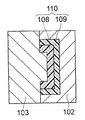
- Patent Document 1 As a conventional in-mold coated product forming mold, a technique for forming an in-mold coated product 110 by the following method using a surface forming mold 101, a coating film forming mold 102, and a back surface forming mold 103 is disclosed in Patent Document 1. Is disclosed.
- the molding cavity 104 is formed by the front surface forming mold 101 and the back surface forming mold 103, the molded article 108 is injection-molded by filling the molding cavity 104 with a molding resin (see FIG. 6A).
- the mold facing the back surface forming mold 103 is switched from the surface forming mold 101 to the coating film forming mold 102, and the surface of the molded product 108 is switched.
- a coating cavity 105 is formed by a gap between the coating film forming mold 102 and the coating film forming mold 102 (see FIG. 6B).
- thermosetting paint made of a liquid thermosetting composition is injected into the coating cavity 105, and a thermosetting paint layer 109 is formed on the surface of the molded article 108, so that an in-mold coated article is obtained. 110 is formed (see FIG. 6C).
- the viscosity of the thermosetting paint for decorating is very low at several tens cps. Therefore, the coating material penetrates and cures even in a slight gap on the parting surface between the coating film forming mold 102 and the back surface forming mold 103 that is generated as an error during mold processing or as a mold scratch while using the mold. As a result, there is a problem that burrs are generated on the outer periphery of the in-mold coated product 110.
- An object of the present invention is to provide an in-mold coated product forming mold that can prevent burrs from occurring on the outer periphery of the in-mold coated product.
- the present invention has the following features in order to achieve the above object.
- a back surface forming mold A surface forming mold that is clamped to the back surface forming mold to form a molding cavity capable of forming a molded product with the surface forming mold; and In place of the front surface forming mold, the back surface forming mold which is clamped with the back surface forming mold and holds the molded product with a coating cavity capable of forming a thermosetting paint layer on the surface of the molded product; A coating film forming mold formed with the coating film forming mold; There is provided an in-mold coated product forming mold provided with a sealing material disposed on at least one of a parting surface of the back surface forming mold and a parting surface of the coating film forming mold.
- the mold according to the first aspect wherein the sealing material is disposed at least at a position adjacent to the coating cavity forming portion of the back surface forming mold constituting the coating cavity. Providing molds for interior coating products.
- the sealing material is located at a position not facing the molding cavity and at a position where the parting surface of the back surface forming mold and the parting surface of the coating film forming mold face each other.
- in-mold coating according to the first aspect wherein the sealing material is disposed at a position adjacent to a molding cavity forming portion of the back surface forming mold constituting the molding cavity.
- the sealing material is disposed at a position adjacent to a molding cavity forming portion of the back surface forming mold constituting the molding cavity.
- the sealing material is disposed at a position adjacent to a coating cavity forming portion of the coating film forming mold constituting the coating cavity.
- the in-mold coated product forming mold of the present invention is applied to the surface forming mold and the back forming mold that can be clamped, or to the back forming mold instead of the surface forming mold.
- a sealing material is disposed on the parting surface of the film forming mold. Therefore, the sealing material that is crushed when the back surface forming mold and the coating film forming mold are clamped fills a slight gap between the back surface forming mold and the coating film forming mold, and the paint leaks. It can prevent the occurrence of burrs around the coated product in the mold.
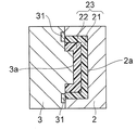
- FIG. 1A is a cross-sectional view showing a process of forming an in-mold coated product with an in-mold coated product forming mold according to an embodiment of the present invention
- FIG. 1B is a cross-sectional view showing a process of forming the in-mold coated product with the in-mold coated product forming mold according to the embodiment of the present invention
- FIG. 1C is a cross-sectional view showing a process of forming the in-mold coated product with the in-mold coated product forming mold according to the embodiment of the present invention
- FIG. 1A is a cross-sectional view showing a process of forming an in-mold coated product with an in-mold coated product forming mold according to an embodiment of the present invention
- FIG. 1B is a cross-sectional view showing a process of forming the in-mold coated product with the in-mold coated product forming mold according to the embodiment of the present invention
- FIG. 1C is a cross-sectional view showing a process of forming
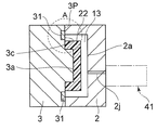
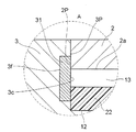
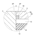
- FIG. 2A is an enlarged partial cross-sectional view of an application portion of the sealing material of the in-mold coated product forming mold according to the embodiment of the present invention
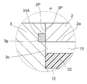
- FIG. 2B is an enlarged partial cross-sectional view of an application location of the sealing material of the in-mold coated product forming mold according to the first modification of the embodiment of the present invention
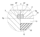
- FIG. 3A is an enlarged partial cross-sectional view of an application portion of the sealing material of the in-mold coated product forming mold according to the second modification of the embodiment of the present invention
- FIG. 3B is an enlarged partial cross-sectional view of an application location of the sealing material of the in-mold coated product forming mold according to the third modification of the embodiment of the present invention
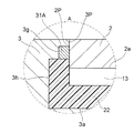
- FIG. 4A is a partial cross-sectional view enlarging an application portion of the sealing material of the in-mold coated product forming mold according to the fourth modified example of the embodiment of the present invention
- FIG. 4B is an enlarged partial cross-sectional view of an application location of the sealing material of the in-mold coated product forming mold according to the fifth modification of the embodiment of the present invention
- FIG. 5 is a schematic view of a paint injection machine used for the in-mold coated product forming mold according to the embodiment of the present invention
- FIG. 6A is a cross-sectional view showing a process of forming an in-mold coated product with a conventional in-mold coated product forming mold
- FIG. 6B is a cross-sectional view showing a process of forming an in-mold coated product using the conventional in-mold coated product forming mold
- FIG. 6C is a cross-sectional view showing a process of forming an in-mold coated product using the conventional in-mold coated product forming mold.
- An in-mold coated product forming mold includes a surface forming mold 1, a coating film forming mold 2, and a back surface forming mold 3, and includes a back surface forming mold 3 and / or a coating film forming.
- Frame-shaped sealing materials 31, 31 ⁇ / b> A, and 32 are arranged on the parting surface of the mold 2 so as to surround at least the coating cavity 13.
- the back surface forming mold 3 is used for forming the back surface shape of the molded product 22. For this reason, the back surface forming mold 3 has a molding cavity forming portion 3a for forming the molding cavity 12 on the parting surface 3P.
- the molding cavity forming part 3a is formed as a convex part as an example in FIG. 1A, but may be a concave part.
- the surface forming mold 1 is used to form the surface shape of the molded product 22. For this reason, the surface forming mold 1 has a molding cavity forming portion 1a for forming the molding cavity 12 on the parting surface 1P.
- the molding cavity forming portion 1a is formed as a concave portion as an example in FIG. 1A, but may be a convex portion.
- the front surface forming mold 1 is disposed at a position facing the back surface forming mold 3 and is clamped between the front surface forming mold 1 and the back surface forming mold 3 when the back surface forming mold 3 is clamped.
- the forming cavity 12 can be formed by the forming portion 1a and the forming cavity forming portion 3a.
- the back surface forming die 3 and the surface forming die 1 are clamped to form the forming cavity forming portion 3a of the back surface forming die 3 and the forming cavity of the surface forming die 1.
- the molded product 22 is formed by filling the molding cavity 12 formed with the portion 1a with the molding resin from the resin injection machine 40 by using the back surface forming mold 3 or the passage 1h penetrating the surface forming mold 1. It is formed by an injection molding resin process (see FIG. 1A).
- the coating film forming mold 2 is a mold that can be clamped with the back surface forming mold 3 instead of the front surface forming mold 1. That is, after forming the molded product 22 between the back surface forming mold 3 and the surface forming mold 1 as described above, it is applied to a position facing the back surface forming mold 3 instead of the surface forming mold 1. After the film forming mold 2 is arranged, the back surface forming mold 3 and the coating film forming mold 2 are clamped.
- the coating film forming mold 2 has an outer shape larger than that of the molding cavity forming portion 1a of the surface forming mold 1 so that a space portion that does not contact the surface of the molded product 22 can be formed on the surface side of the molded product 22.
- the coating cavity forming portion 2a is configured.
- the coating cavity forming portion 2 a that is a non-contacting space portion corresponds to the coating cavity 13. That is, the coating cavity 13 includes the surface of the molded product 22, a part of the parting surface 3 ⁇ / b> P (the coating cavity forming portion 3 c described later) of the back surface forming mold 3, and the coating cavity forming portion 2 a of the coating film forming mold 2. Formed between. After forming the molded product 22, in a state where the back surface forming mold 3 holds the molded product 22, the mold facing the back surface forming mold 3 is switched from the front surface forming mold 1 to the coating film forming mold 2. A coating cavity 13 is formed on the surface of the product 22 by a gap such as a coating cavity forming portion 2a (see FIG. 1B).
- the molded product 22 is bitten into an ejector pin (not shown) formed on the back surface forming mold 3 as in general molding. Accordingly, the molded product 22 can be held so as not to be detached from the back surface forming mold 3.
- thermosetting paint for decoration made of a liquid thermosetting composition is injected into the coating cavity 13 from a paint injector 41 described later, and a thermosetting paint layer 21 is formed on the surface of the molded product 22.
- the in-mold coated product 23 is formed (see FIG. 1C).
- a part of the parting surface 3P of the back surface forming mold 3 more specifically, at least at the position of the coating cavity forming portion 3c of the back surface forming mold 3 or at a position adjacent to the coating cavity forming portion 3c.
- a shaped sealing material 31 is formed. As an example, as shown in FIG.
- the sealing material 31 is disposed so as to fit in the frame-shaped recess 3 f of the parting surface 3 ⁇ / b> P of the back surface forming mold 3, and seals more than the depth of the recess 3 f.
- the material 31 has a slightly large thickness. Therefore, when the sealing material 31 is attached to the recess 3f, the sealing material 31 slightly protrudes from the recess 3f.
- the sealing material 31 crushed by the parting surface 2P of the coating film forming mold 2 and the molded product 22 when the back surface forming mold 3 and the coating film forming mold 2 are clamped is The slight gap between the coating film forming mold 2 and the small gap between the molded product 22 and the coating film forming mold 2 are filled to prevent the paint from leaking, and the outer periphery of the in-mold coated product 23 Can be prevented.
- the sealing material 31 forms an end of the coating cavity 13 on the parting surface 3P side of the back surface forming mold 3.
- the Young's modulus is lower than the mold materials used for the molds 1, 2, 3. It is important.
- a fluorine compound, a silicon compound, tin, zinc, lead, or the like may be used.
- the sealing materials 31, 31A, 32 are coated on the molds 3, 2.
- the sealing materials 31, 31 ⁇ / b> A, and 32 may be attached to the molds 3 and 2.
- the sealing materials 31, 31 ⁇ / b> A, and 32 should have good releasability from the thermosetting paint for forming the thermosetting paint layer 21 in the coating cavity 13.
- the sealing materials 31, 31A, 32 are fixed to the thermosetting paint, the sealing materials 31, 31A, 32 are used when the mold is opened or when the in-mold coated product 23 is taken out from the mold 3, 2. This is because there is a risk of falling off from the molds 3 and 2, or the in-mold coated product 23 being pulled toward the sealing material 31, 31A, 32 side and deformed.
- FIG. 2A and FIG. 2B are partial cross-sectional views in which the application location A (see FIG. 1B) of the sealing material 31 is enlarged.
- the sealing material 31 may be extended and arranged so as to face the molding cavity 12 and form the outer shape of the molded product 22 on the parting surface 3P of the back surface forming mold 3 (see FIG. 2A).
- the sealing material 31 is a soft sealing material, it may be crushed and deformed by the molding resin injected at a high pressure into the molding cavity 12, and as a result, the shape of the molded product 22 may be defective. Therefore, when the sealing material 31 is arranged as shown in FIG. 2A, the material of the sealing material 31 is hard enough to be crushed by the molding resin injected at a high pressure into the molding cavity 12 and does not deform, and has a sealing effect. It is preferable to use a material that can also exhibit the above.
- the frame-shaped sealing material 31A does not face the molding cavity 12 on the parting surface 3P of the back surface forming mold 3, the outer shape of the molded product 22 is obtained. Since the sealing material 31A is not formed, the shape defect of the molded product 22 does not occur, and since the sealing material 31A is not deformed by the thermosetting paint injected at a low pressure because of low viscosity, the thermosetting paint layer No shape defects 21 occur, which is preferable (see FIG. 2B). That is, in FIG.
- a frame-shaped recess 3g is provided, and a frame-shaped seal material 31A made of the same material as the seal material 31 is disposed in the recess 3g.
- the sealing material 31 ⁇ / b> A has a thickness that is slightly larger than the depth of the recess 3 g of the parting surface 3 ⁇ / b> P of the back surface forming mold 3. Therefore, when the sealing material 31A is attached to the recess 3g, the sealing material 31A slightly protrudes from the recess 3g.
- the sealing material 31A crushed by the parting surface 2P of the coating film forming mold 2 when the back surface forming mold 3 and the coating film forming mold 2 are clamped is used as the back surface forming mold 3 and the coating film forming mold.
- the sealing material 32 formed on the coating film forming mold 2 has a parting surface 2P adjacent to the coating cavity forming portion 2a of the coating film forming mold 2.
- positioned in FIG. 3 is demonstrated in detail (refer FIG. 3A and 3B).
- FIG. 3A and 3B are partial cross-sectional views in which the application portion A (see FIG. 1B) of the sealing material 32 is enlarged.
- the sealing material 32 may be disposed only on the coating film forming mold 2 (see FIG. 3A). However, when the sealing material 32 is disposed in combination with the sealing material 31 formed on the back surface forming mold 3, the effect of preventing coating leakage is obtained. It can be expected to be higher (see FIG. 3B).
- the parting surface 2P of the coating film forming mold 2 is such that the side surface faces the coating cavity 13 (the position where the back surface forming mold 3 and the coating film forming mold 2 are in direct contact with each other)
- a frame-shaped recess 2g is provided at a position facing the cavity 13, and a frame-shaped seal material 32 of the same material as the seal material 31 is disposed in the recess 2g.
- the sealing material 32 has a thickness slightly larger than the depth of the recess 2g of the parting surface 2P of the coating film forming mold 2 as an example.
- the sealing material 32 will protrude a little from the recessed part 2g. Therefore, the sealing material 32 crushed by the parting surface 3P of the back surface forming die 3 when the back surface forming die 3 and the coating film forming die 2 are clamped is used as the back surface forming die 3 and the coating film forming die. 2 can be filled to prevent the paint from leaking, and the occurrence of burrs on the outer periphery of the in-mold coated product 23 can be prevented.
- the sealing material 31A is disposed in the recess 3g of the parting surface 3P of the back surface forming mold 3 in FIG. 2B, and the party of the coating film forming mold 2 in FIG. 3A is opposed to the sealing material 31A.
- the sealing material 32 is configured to be disposed in the concave portion 2g of the sealing surface 2P. Therefore, when the sealing material 31A is attached to the recess 3g and the sealing material 32 is attached to the recess 2g, the sealing material 31A slightly protrudes from the recess 3g and the sealing material 32 slightly protrudes from the recess 2g. Alternatively, either one of the sealing material 31A and the sealing material 32 may slightly protrude from the recess 3g or the recess 2g.
- the sealing materials 31 and 31A formed on the back surface forming mold 3 are applied to the parting surface 3P adjacent to the molding cavity forming portion of the back surface forming mold 3.
- the arrangement mode will be described in detail (see FIGS. 4A and 4B).
- FIG. 4A and FIG. 4B are partial cross-sectional views in which the application portion A (see FIG. 1B) of the sealing material 31 is enlarged.
- a part of the molding cavity 12 may include a molding cavity forming recess 3 h carved in the back surface forming mold 3. That is, the molding cavity 12 may be constituted by the molding cavity forming portion 1a of the front surface forming mold 1, the molding cavity forming portion 3a of the back surface forming die 3, and the molding cavity forming concave portion 3h.
- the molding cavity forming recess 3h and the parting surface 3P are adjacent to each other.
- the outermost position of the molded product 22 may be flush with the coating cavity forming portion 2a of the coating film forming mold 2 (see FIG. 4A).
- the outermost position of the molded product 22 may be set to the outside of the coating cavity forming portion 2a of the coating film forming mold 2 so that paint leakage does not occur outside the molded product 22 (FIG. 4B). reference). That is, by extending the molding cavity forming recess 3h to the outside of FIG. 4A and disposing the recess 3g to the outside of FIG. 4A, a part of the molding cavity forming recess 3h is part of the coating film forming mold 2. It may be made to face the parting surface 2P.
- thermosetting paint for example, an oligomer such as a urethane acrylate oligomer having at least two (meth) acrylate groups, an epoxy acrylate oligomer, or a resin thereof, which uses an organic peroxide as an initiator for the curing reaction, or 20% to 70% by weight of unsaturated polyester resin, methyl (meth) acrylate, ethyl (meth) acrylate, propyl (meth) acrylate, butyl (meth) acrylate, 2-ethylhexyl (meth) acrylate, (meth) acrylic acid,
- a radical scavenger mainly composed of vinyl acetate, tripropylene glycol diacrylate, 1,6-hexanediol diacrylate, or a vehicle component comprising 80 to 30% by weight of a copolymerizable ethylenically unsaturated monomer such as styrene.
- the coating material injection machine 41 applies pressure to the upper part of the coating material tank 43 so that an accurate amount of the thermosetting coating material 44 for one shot is transferred from the coating material tank 43 to the coating material injection unit 42 having the structure of metering / injection / valve. It has a structure to be sent (see FIG. 5).
- the position setting of the coating material injection unit 42 it may be provided inside the coating film forming mold 2.
- a thermosetting paint injection port provided in the coating film forming mold 2 is provided on the mating surface with the back surface forming mold 3, and the longitudinal axis direction of the paint injection unit 42 and the resin injection unit of the resin injection machine 41 are provided. You may arrange
- the coating material injection unit 42 moves forward and directly touches the coating film forming mold 2, and the thermosetting coating material is transferred from the coating material injection unit 42 to the coating film forming mold 2.
- the structure is such that it is injected into the coating cavity 13 through a paint gate 2j (see FIG. 1B) provided in the mold 2.
- the molding resin is not particularly limited, such as a normal thermoplastic injection molding resin or engineering plastic, or a thermosetting molding resin material. However, a molding resin that is easy to mold and has good adhesion to the thermosetting paint is preferable. Specific examples of the molding resin include acrylonitrile butadiene styrene resin (ABS resin), polyamide resin, polyethylene resin, polyester resin, polypropylene resin, polybutylene terephthalate resin, and polycarbonate resin. It is done.
- the molding resin is filled into the molding cavity 12 by the resin injector 40.
- An injection molding machine can be used as the resin injection machine 40.
- the in-mold coated product forming mold according to the above embodiment of the present invention is provided with a plurality of back surface forming molds 3 so that the movable plate or the rotating plate attached to the movable plate rotates.
- the surface forming mold 1 and the coating film forming mold 2 are respectively fixed to a stationary platen and moved to a position between the surface forming mold 1 and the coating film forming mold 2.
- a board or a rotating board may be disposed, and the back surface forming mold 3 may be fixed to the movable board of the injection molding machine or the rotating board attached to the movable board.
- the back surface forming mold 3 may be fixed to a stationary platen, and the front surface forming die 1 and the coating film forming die 2 may be fixed to a movable plate of an injection molding machine or a rotating plate attached to the movable platen.
- thermosetting is performed by the back surface forming mold 3 and the coating film forming die 2 holding another molded product 22.
- the in-mold coated product 23 can be manufactured at the same time as forming the conductive paint layer 21, that is, forming the molded product 22.
- the sealing materials 31, 31 ⁇ / b> A, and 32 that are crushed when the back surface forming mold 3 and the coating film forming mold 2 are clamped are the back surface forming mold 3 and the coating film forming mold 2. It is possible to prevent the paint from leaking by filling a slight gap therebetween, and to prevent the occurrence of burrs on the outer periphery of the in-mold coated product 23.
- An in-mold coated article 23 was manufactured using an in-mold coated article forming mold including a front surface forming mold 1, a coating film forming mold 2 and two back forming molds 3 each having a cavity on each of the front and back surfaces. .
- a coating film injection unit 42 having a paint injection port was used as the coating film forming mold 2.
- a parting surface having a sealing material 31 disposed adjacent to the coating cavity forming portion of the back surface forming mold 3 and not facing the molding cavity 12 was used.
- an injection molding machine for two-color molding in which a rotating disk attached to a movable plate rotates was used.
- a molding cavity 12 formed by closing the back surface forming mold 3 facing the surface forming mold 1 with respect to the surface forming mold 1 is filled with a heat-melted solid color heat-resistant ABS resin, and cooled and solidified to form.
- Product 22 was formed (see FIG. 1A).
- the rotating disk of the injection molding machine is rotated so that the mold facing the back surface forming mold 3 is transferred from the surface forming mold 1 to the coating film forming mold 2 while the back surface forming mold 3 holds the molded product 22.
- the back surface forming mold 3 and the coating film forming mold 2 were closed to form a coating cavity 13 for coating the molded product 22 with a thermosetting paint (see FIG. 1B).
- An in-mold coated product 23 was formed by injecting a thermosetting paint (Praglas 8000 manufactured by Dainippon Paint Co., Ltd.) into the coating cavity 13 to form the thermosetting paint layer 21 (see FIG. 1C).
- the sealing material 31 is crushed, and a slight gap between the back surface forming die 3 and the coating film forming die 2 is filled.
- the burr due to the thermosetting paint layer 21 did not occur on the outer periphery of the in-mold coated product 23.
- the shape defect of the molded article 22 and the thermosetting paint layer 21 did not occur.
- Example 1 except that a sealing material 32 is formed on the coating film forming mold 2 and an in-mold coated product forming mold disposed on the parting surface adjacent to the coating cavity forming portion of the coating film forming mold 2 is used.
- an in-mold coated product 23 was formed (see FIG. 3A).
- the sealing material 32 is crushed when the back surface forming mold 3 and the coating film forming mold 2 are clamped, and a slight gap is formed between the back surface forming mold 3 and the coating film forming mold 2. Since the paint was prevented from leaking by filling, the burr due to the thermosetting paint layer 21 did not occur on the outer periphery of the in-mold coated product 23.
- the in-mold coated product forming mold according to the present invention is such that the sealing material crushed when the back surface forming mold and the coating film forming mold are clamped is slightly between the back surface forming mold and the coating film forming mold. Therefore, it is possible to prevent the paint from leaking by filling a gap, and to prevent the occurrence of burrs on the outer periphery of the in-mold coated product.
Landscapes
- Engineering & Computer Science (AREA)
- Manufacturing & Machinery (AREA)
- Mechanical Engineering (AREA)
- Moulds For Moulding Plastics Or The Like (AREA)
- Injection Moulding Of Plastics Or The Like (AREA)
Abstract
La présente invention se rapporte à une matrice de formation d'un objet enduit dans le moule. Des matériaux d'étanchéité (31, 31A, 32) sont placés sur la surface de séparation (3P) d'une matrice de formation de surface arrière (3) qui peut se caler sur une matrice de formation de surface avant (1), ou sur la surface de séparation (2P) d'une matrice de formation de film (2) qui peut se caler sur la matrice de formation de surface arrière (3) au lieu de la matrice de formation de surface avant (1).
Applications Claiming Priority (2)
| Application Number | Priority Date | Filing Date | Title |
|---|---|---|---|
| JP2009-063733 | 2009-03-17 | ||
| JP2009063733A JP2010214745A (ja) | 2009-03-17 | 2009-03-17 | 型内塗装品形成金型 |
Publications (1)
| Publication Number | Publication Date |
|---|---|
| WO2010106968A1 true WO2010106968A1 (fr) | 2010-09-23 |
Family
ID=42739628
Family Applications (1)
| Application Number | Title | Priority Date | Filing Date |
|---|---|---|---|
| PCT/JP2010/054178 Ceased WO2010106968A1 (fr) | 2009-03-17 | 2010-03-12 | Matrice de formation d'objet enduit dans un moule |
Country Status (3)
| Country | Link |
|---|---|
| JP (1) | JP2010214745A (fr) |
| TW (1) | TW201043438A (fr) |
| WO (1) | WO2010106968A1 (fr) |
Cited By (1)
| Publication number | Priority date | Publication date | Assignee | Title |
|---|---|---|---|---|
| EP3536476A1 (fr) | 2018-02-28 | 2019-09-11 | VKR Holding A/S | Dispositif de moulage et procédé de production d'un châssis ou d'un cadre de fenêtre sans bavure |
Families Citing this family (4)
| Publication number | Priority date | Publication date | Assignee | Title |
|---|---|---|---|---|
| KR20180023764A (ko) * | 2016-08-26 | 2018-03-07 | (주) 우성정공 | 휘광제 뭉침방지 사출장치 및 이를 이용한 사출방법 |
| JP6926985B2 (ja) * | 2017-11-22 | 2021-08-25 | 株式会社デンソー | 熱交換器のタンク及び熱交換器のタンクの製造方法 |
| IT201900025120A1 (it) * | 2019-12-20 | 2021-06-20 | De Longhi Appliances Srl | Apparato e metodo di realizzazione di un componente in materiale plastico, e componente in materiale plastico |
| EP4467317A1 (fr) * | 2023-05-24 | 2024-11-27 | ABB Schweiz AG | Insert de moule pour moulage par injection, moule pour moulage par injection et procédé de production d'un insert de moule pour moulage par injection |
Citations (4)
| Publication number | Priority date | Publication date | Assignee | Title |
|---|---|---|---|---|
| JPH0352114U (fr) * | 1989-09-29 | 1991-05-21 | ||
| JPH06328505A (ja) * | 1993-05-26 | 1994-11-29 | Dainippon Toryo Co Ltd | 射出成形金型 |
| JPH11333850A (ja) * | 1998-05-28 | 1999-12-07 | Asahi Chem Ind Co Ltd | 樹脂成形方法 |
| JP2003334838A (ja) * | 2002-03-14 | 2003-11-25 | Nippon Bee Chemical Co Ltd | 金型交換による成形品の射出及び加飾成形方法 |
-
2009
- 2009-03-17 JP JP2009063733A patent/JP2010214745A/ja not_active Withdrawn
-
2010
- 2010-03-12 WO PCT/JP2010/054178 patent/WO2010106968A1/fr not_active Ceased
- 2010-03-16 TW TW099107587A patent/TW201043438A/zh unknown
Patent Citations (4)
| Publication number | Priority date | Publication date | Assignee | Title |
|---|---|---|---|---|
| JPH0352114U (fr) * | 1989-09-29 | 1991-05-21 | ||
| JPH06328505A (ja) * | 1993-05-26 | 1994-11-29 | Dainippon Toryo Co Ltd | 射出成形金型 |
| JPH11333850A (ja) * | 1998-05-28 | 1999-12-07 | Asahi Chem Ind Co Ltd | 樹脂成形方法 |
| JP2003334838A (ja) * | 2002-03-14 | 2003-11-25 | Nippon Bee Chemical Co Ltd | 金型交換による成形品の射出及び加飾成形方法 |
Cited By (1)
| Publication number | Priority date | Publication date | Assignee | Title |
|---|---|---|---|---|
| EP3536476A1 (fr) | 2018-02-28 | 2019-09-11 | VKR Holding A/S | Dispositif de moulage et procédé de production d'un châssis ou d'un cadre de fenêtre sans bavure |
Also Published As
| Publication number | Publication date |
|---|---|
| TW201043438A (en) | 2010-12-16 |
| JP2010214745A (ja) | 2010-09-30 |
Similar Documents
| Publication | Publication Date | Title |
|---|---|---|
| US7832999B2 (en) | Method of forming a coating layer on the surface of a molded product within a mold | |
| CN103009549B (zh) | 复合成形品的成形方法 | |
| JP2009101670A (ja) | 型内塗装品の製造方法および型内塗装品形成装置 | |
| US20090085235A1 (en) | Method and apparatus for making a microstructured or nanostructured article | |
| CN102615771B (zh) | 一种模内镶件注塑贴合方法 | |
| US7862758B2 (en) | In-mold coat-forming method | |
| JP2010214745A (ja) | 型内塗装品形成金型 | |
| CN1328031C (zh) | 模内被覆成形用金属模及模内被覆成形方法 | |
| JP2010234647A (ja) | 型内塗装品の製造方法およびこれに使用する金型 | |
| US8047827B2 (en) | Mold for in-mold coating formation | |
| KR101488186B1 (ko) | 도광판 제작을 위한 저압 사출압축성형 방법 | |
| JP4614812B2 (ja) | 型内被覆成形装置及び型内被覆成形方法 | |
| JP5557106B2 (ja) | 金型内塗装用金型及び金型内塗装方法 | |
| JP5541579B2 (ja) | 金型内塗装用金型及び金型内塗装方法 | |
| US7479244B2 (en) | Process for the production of plates made of transparent plastic material with non-transparent areas | |
| JP4407810B2 (ja) | 型内被覆成形用金型 | |
| JP2009160756A (ja) | 型内塗装品の製造方法および型内塗装品形成装置 | |
| JP2009220464A (ja) | 型内塗装品形成金型および型内塗装品の製造方法 | |
| JP2009220465A (ja) | 型内塗装品形成金型および型内塗装品の製造方法 | |
| KR102368162B1 (ko) | 압축 확산 사출 성형 금형 및 이를 이용한 박형 제품 성형 방법 | |
| JP5093744B2 (ja) | 型内被覆成形用金型 | |
| JP5286656B2 (ja) | 型内被覆成形用金型 | |
| JP2012086367A (ja) | 型内被覆成形方法 | |
| JP2010188594A (ja) | 型内塗装品形成金型および型内塗装品の製造方法 | |
| JP2005199641A (ja) | 型内被覆成形方法及び型内被覆成形用金型 |
Legal Events
| Date | Code | Title | Description |
|---|---|---|---|
| 121 | Ep: the epo has been informed by wipo that ep was designated in this application |
Ref document number: 10753460 Country of ref document: EP Kind code of ref document: A1 |
|
| NENP | Non-entry into the national phase |
Ref country code: DE |
|
| 122 | Ep: pct application non-entry in european phase |
Ref document number: 10753460 Country of ref document: EP Kind code of ref document: A1 |