WO2010109828A1 - パイプ連結用コネクタ - Google Patents
パイプ連結用コネクタ Download PDFInfo
- Publication number
- WO2010109828A1 WO2010109828A1 PCT/JP2010/001951 JP2010001951W WO2010109828A1 WO 2010109828 A1 WO2010109828 A1 WO 2010109828A1 JP 2010001951 W JP2010001951 W JP 2010001951W WO 2010109828 A1 WO2010109828 A1 WO 2010109828A1
- Authority
- WO
- WIPO (PCT)
- Prior art keywords
- pipe
- connector
- lock member
- locking piece
- state
- Prior art date
- Legal status (The legal status is an assumption and is not a legal conclusion. Google has not performed a legal analysis and makes no representation as to the accuracy of the status listed.)
- Ceased
Links
Images

Classifications
-
- F—MECHANICAL ENGINEERING; LIGHTING; HEATING; WEAPONS; BLASTING
- F16—ENGINEERING ELEMENTS AND UNITS; GENERAL MEASURES FOR PRODUCING AND MAINTAINING EFFECTIVE FUNCTIONING OF MACHINES OR INSTALLATIONS; THERMAL INSULATION IN GENERAL
- F16L—PIPES; JOINTS OR FITTINGS FOR PIPES; SUPPORTS FOR PIPES, CABLES OR PROTECTIVE TUBING; MEANS FOR THERMAL INSULATION IN GENERAL
- F16L37/00—Couplings of the quick-acting type
- F16L37/08—Couplings of the quick-acting type in which the connection between abutting or axially overlapping ends is maintained by locking members
- F16L37/12—Couplings of the quick-acting type in which the connection between abutting or axially overlapping ends is maintained by locking members using hooks, pawls, or other movable or insertable locking members
-
- F—MECHANICAL ENGINEERING; LIGHTING; HEATING; WEAPONS; BLASTING
- F16—ENGINEERING ELEMENTS AND UNITS; GENERAL MEASURES FOR PRODUCING AND MAINTAINING EFFECTIVE FUNCTIONING OF MACHINES OR INSTALLATIONS; THERMAL INSULATION IN GENERAL
- F16L—PIPES; JOINTS OR FITTINGS FOR PIPES; SUPPORTS FOR PIPES, CABLES OR PROTECTIVE TUBING; MEANS FOR THERMAL INSULATION IN GENERAL
- F16L37/00—Couplings of the quick-acting type
- F16L37/08—Couplings of the quick-acting type in which the connection between abutting or axially overlapping ends is maintained by locking members
- F16L37/084—Couplings of the quick-acting type in which the connection between abutting or axially overlapping ends is maintained by locking members combined with automatic locking
- F16L37/098—Couplings of the quick-acting type in which the connection between abutting or axially overlapping ends is maintained by locking members combined with automatic locking by means of flexible hooks
- F16L37/0985—Couplings of the quick-acting type in which the connection between abutting or axially overlapping ends is maintained by locking members combined with automatic locking by means of flexible hooks the flexible hook extending radially inwardly from an outer part and engaging a bead, recess or the like on an inner part
- F16L37/0987—Couplings of the quick-acting type in which the connection between abutting or axially overlapping ends is maintained by locking members combined with automatic locking by means of flexible hooks the flexible hook extending radially inwardly from an outer part and engaging a bead, recess or the like on an inner part the flexible hook being progressively compressed by axial tensile loads acting on the coupling
-
- F—MECHANICAL ENGINEERING; LIGHTING; HEATING; WEAPONS; BLASTING
- F16—ENGINEERING ELEMENTS AND UNITS; GENERAL MEASURES FOR PRODUCING AND MAINTAINING EFFECTIVE FUNCTIONING OF MACHINES OR INSTALLATIONS; THERMAL INSULATION IN GENERAL
- F16L—PIPES; JOINTS OR FITTINGS FOR PIPES; SUPPORTS FOR PIPES, CABLES OR PROTECTIVE TUBING; MEANS FOR THERMAL INSULATION IN GENERAL
- F16L37/00—Couplings of the quick-acting type
- F16L37/08—Couplings of the quick-acting type in which the connection between abutting or axially overlapping ends is maintained by locking members
- F16L37/084—Couplings of the quick-acting type in which the connection between abutting or axially overlapping ends is maintained by locking members combined with automatic locking
- F16L37/098—Couplings of the quick-acting type in which the connection between abutting or axially overlapping ends is maintained by locking members combined with automatic locking by means of flexible hooks
-
- F—MECHANICAL ENGINEERING; LIGHTING; HEATING; WEAPONS; BLASTING
- F16—ENGINEERING ELEMENTS AND UNITS; GENERAL MEASURES FOR PRODUCING AND MAINTAINING EFFECTIVE FUNCTIONING OF MACHINES OR INSTALLATIONS; THERMAL INSULATION IN GENERAL
- F16L—PIPES; JOINTS OR FITTINGS FOR PIPES; SUPPORTS FOR PIPES, CABLES OR PROTECTIVE TUBING; MEANS FOR THERMAL INSULATION IN GENERAL
- F16L37/00—Couplings of the quick-acting type
- F16L37/08—Couplings of the quick-acting type in which the connection between abutting or axially overlapping ends is maintained by locking members
- F16L37/084—Couplings of the quick-acting type in which the connection between abutting or axially overlapping ends is maintained by locking members combined with automatic locking
- F16L37/098—Couplings of the quick-acting type in which the connection between abutting or axially overlapping ends is maintained by locking members combined with automatic locking by means of flexible hooks
- F16L37/0982—Couplings of the quick-acting type in which the connection between abutting or axially overlapping ends is maintained by locking members combined with automatic locking by means of flexible hooks with a separate member for releasing the coupling
-
- F—MECHANICAL ENGINEERING; LIGHTING; HEATING; WEAPONS; BLASTING
- F16—ENGINEERING ELEMENTS AND UNITS; GENERAL MEASURES FOR PRODUCING AND MAINTAINING EFFECTIVE FUNCTIONING OF MACHINES OR INSTALLATIONS; THERMAL INSULATION IN GENERAL
- F16L—PIPES; JOINTS OR FITTINGS FOR PIPES; SUPPORTS FOR PIPES, CABLES OR PROTECTIVE TUBING; MEANS FOR THERMAL INSULATION IN GENERAL
- F16L37/00—Couplings of the quick-acting type
- F16L37/08—Couplings of the quick-acting type in which the connection between abutting or axially overlapping ends is maintained by locking members
- F16L37/10—Couplings of the quick-acting type in which the connection between abutting or axially overlapping ends is maintained by locking members using a rotary external sleeve or ring on one part
- F16L37/113—Couplings of the quick-acting type in which the connection between abutting or axially overlapping ends is maintained by locking members using a rotary external sleeve or ring on one part the male part having lugs on its periphery penetrating into the corresponding slots provided in the female part
Definitions
- the present invention relates to a pipe connection connector for connecting a pipe to a connection target.
- a connector for connecting a plastic hose and a pipe provided in a housing of an automobile radiator, a cylindrical sleeve to which the hose is connected, and a connecting position and a connecting release position with respect to the cylindrical sleeve
- a device provided with a blocking device that is mounted so as to be movable between them, and is provided with an arm that locks the hose at the connecting position see Patent Document 1.
- the arm of the blocking device is formed so as to bend elastically in the radial direction, and when the blocking device is in the coupling position, it is in a recess radially inward of the hook provided on one end side of the arm.
- the ribs protruding from the outer peripheral surface of the hose are fitted, and the inclined surface on the radially outer side of the hook contacts the inner edge (radially inner edge) of the hole in the cylindrical sleeve, thereby Is prevented from being bent (that is, release of the fitting of the ribs).
- the relative movement between the blocking device and the cylindrical sleeve releases the contact of the arm hook with the hole of the cylindrical sleeve, and By the relative movement with the hose, the hook moves over the rib so as to push the arm radially outward, and the fitting of the rib to the recess of the hook is released.
- the conventional connector since the conventional connector has a configuration in which the hook passes over the rib so as to push the arm outward in the radial direction when the connection is released, the user needs a large operating force and the operability is poor. There was a problem.
- one side surface of the recess of the hook in order to reduce the operating force when releasing the connection, one side surface of the recess of the hook is formed as an inclined surface, and this inclined surface has a rib fitted into the recess. Since it is also a surface to be locked, there is a problem that it is difficult to stably hold the connection.
- the above conventional connector has a problem that it cannot maintain the coupling state with the hose when the hook dent or the hose rib is deformed or damaged due to repeated connection and disconnection operations. .
- An object of the present invention is to provide a connector for connecting pipes.
- a connector (1) for pipe connection for connecting a pipe (2) to a connection object Comprising: The connector main body (3) by which the said pipe is inserted / removed A lock member (4) that is slidably held by the connector main body and fixes the pipe by a locking piece (42, 42); and an operation piece (43, 43) that is used for a slide operation of the lock member. ), And the locking piece is fixed to the pipe by being pressed by the first pressing portion (55) formed in the connector body when the locking member is slid. Therefore, the pipe is elastically deformed into a released state in which the pipe is released.
- the locking piece is extended from the base portion (41) of the lock member in the insertion direction of the pipe, and the free end thereof rides on the first pressing portion of the connector body. It can be set as the structure which elastically deforms to the said cancellation
- the locking piece includes a first restricting portion (53) for restricting movement of the pipe in the detaching direction when in the fixed state, and a contact formed on the connector body. It can be set as the structure which has a 2nd control part (51) which controls the elastic deformation from the said fixed state to the said cancellation
- the operation piece extends from the base of the lock member in the insertion direction of the pipe, and when the locking piece is in a released state, the free end side is the connector body. It can be set as the structure which elastically deforms by riding on the 2nd press part (24) formed in this.
- the base portion of the lock member has a ring shape, and the locking piece and the operation piece are spaced apart from each other in the circumferential direction of the base portion of the lock member and extend.
- the locking piece may be disposed inside the connector body, and the operation piece may be disposed outside the connector body.
- the connector body is provided with an engagement hole (23) that engages with the locking piece, and the locking piece is elastically deformed to the released state when the engagement piece is engaged. It can be set as the structure which protrudes outside the said connector main body from a joint hole.
- the first pressing portion can be formed at the opening edge of the engagement hole.
- the locking piece of the lock member that has been slid is pressed by the first pressing portion formed in the connector body, so that it is elastically deformed from the fixed state to the released state. Therefore, when the pipe is connected, the connection state is stably maintained, and at the time of releasing the connection of the pipe, the user can obtain good operability without requiring a large operating force to pull out the pipe. There is an effect.
- the free end side of the locking piece that is, the portion for locking the pipe
- the free end side of the locking piece that is, the portion for locking the pipe
- the elastic recovery force of the locking piece acts as a force for sliding the locking member toward the side where the locking piece is fixed, the user does not need a large operating force to slide the locking member, and is good. Operability is obtained.
- the second restricting portion restricts the locking piece from moving in the pipe detachment direction by the first restricting portion. Since the elastic deformation of the pipe is restricted (that is, the restriction of the first restricting portion is prevented from being released), the connected state of the pipe is more stably maintained.
- the elastic recovery force of the operation piece acts as a force for sliding the lock member to the side where the locking piece is fixed, the user can perform a large operation on the slide of the lock member. Good operability can be obtained without requiring force.
- the elastic recovery force of the operation piece acts so as to always return the lock member to the position where the lock piece is in the initial state, the creep generated when the lock piece is maintained in an elastically deformed state. The phenomenon can be prevented.
- the latching piece and operation piece of a locking member are realizable by simple and compact structure.
- the locking piece can be elastically deformed to the released state without complicating the configuration of the connector main body and the lock member.
- a 1st press part is easily realizable, without complicating the structure of a connector main body.
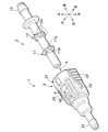
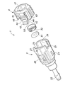
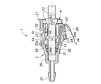
- the perspective view of the connector for pipe connection which concerns on embodiment The disassembled perspective view of the connector for pipe connection which concerns on embodiment
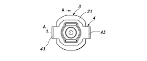
- the rear view of the connector for pipe connection concerning an embodiment 4 is a cross-sectional view taken along line AA in FIG. 4 showing one operation state of the connector for pipe connection according to the embodiment.
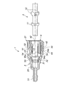
- 4 is a cross-sectional view taken along line AA in FIG. 4 showing one operation state of the connector for pipe connection according to the embodiment.
- 4 is a cross-sectional view taken along line AA in FIG. 4 showing one operation state of the connector for pipe connection according to the embodiment.
- 4 is a cross-sectional view taken along line AA in FIG. 4 showing one operation state of the connector for pipe connection according to the embodiment.
- 4 is a cross-sectional view taken along line AA in FIG. 4 showing one operation state of the connector for pipe connection according to the embodiment.
- 4 is a cross-sectional view taken along line AA in FIG. 4 showing one operation state of the connector for pipe connection according to the embodiment.
- the terms “up”, “down”, “front”, “back”, “left”, and “right” indicating directions are defined according to the directions shown in FIG. .
- the insertion direction (arrow A direction) along the axis of the pipe 2 with respect to the connector 1 shown in FIG. 1 corresponds to “front”, and the opposite direction corresponds to “rear”.
- a pipe connection connector (hereinafter simply referred to as a connector) 1 is used to connect a fluid transport pipe 2 to a connection target (not shown). It is mainly composed of a connector main body 3 into which the pipe 2 is inserted and removed, and a lock member 4 which is slidably held by the connector main body 3 and fixes the pipe 2 according to the sliding operation.
- the pipe 2 includes a front flange 11 that is locked to the lock member 4, a pair of bumps 12 that are provided at the rear of the flange 11, and a rear end. And a hose connection portion 13 provided at the top.
- the flange portion 11 includes an annular portion 11a and a plurality of rib portions 11b arranged at equal intervals in the circumferential direction on the front side of the annular portion 11a. Inclined from the surface side toward the rear. Each protrusion 12 has three protrusions 12a.
- a hose (not shown) for fluid transportation is connected to the hose connection portion 13.
- the connector main body 3 is made of a synthetic resin material, and as shown in FIG. 2, a rear cylindrical portion 21 in which the lock member 4 is accommodated, and a hose connection portion 22 provided at the front end of the cylindrical portion 21. It has.
- the connector body 3 has a substantially symmetrical shape in the vertical and horizontal directions.
- the cylindrical portion 21 has openings 23 formed on the upper and lower walls thereof, and pressing portions 24 project from the left and right side walls toward the outside.
- the notch 25 which the base end part (connection part with the ring part 41) of the operation pieces 43 and 43 fits is formed in the rear edge of the right-and-left side wall.
- a fluid transport hose (not shown) to be connected to the pipe 2 is connected to the hose connection portion 22.
- the insertion hole 26 of the connector 1 into which the pipe 2 is inserted and removed has an O-ring 31 for sealing the flow path and a cylindrical shape that fixes the O-ring 31 in the insertion hole 26.
- the bush 32 is attached.
- the lock member 4 is made of a synthetic resin material, and as shown in FIG. 2, an annular ring portion 41 forming a base portion thereof, and a pair of upper and lower locking pieces 42 and 42 extending forward from the ring portion 41. And a pair of left and right operation pieces 43, 43 extending forward from the ring portion 41, and a pair of left and right guide pieces 44, 44 extending forward from the ring portion 41 inside the operation pieces 43, 43. ing.
- the locking pieces 42, 42 are arranged at approximately the middle position of the space between the operation pieces 43, 43, and an outer locking claw 51 protruding from the outer surface thereof and an inner engagement protruding from the inner surface thereof. And a pawl (first restricting portion) 53.
- the operation pieces 43 and 43 are used by the user to pick the finger with a finger to perform the slide operation of the lock member 4, and the outer surface thereof is uneven to prevent slipping. Further, the guide pieces 44 and 44 are disposed to face the operation pieces 43 and 43 with a gap equivalent to the thickness of the left and right side walls of the tubular portion 21 in the connector main body 3, respectively.
- the locking pieces 42 and 42 are disposed inside the connector main body 3, and the distal end side thereof is exposed from the opening 23 of the connector main body 3. .
- the lock member 4 is sandwiched by the operation pieces 43 and 43 and the guide pieces 44 and 44 arranged on the outer side and the inner side of the connector body 3, respectively, on the left and right side walls of the cylindrical part 21 behind the pressing part 24. 50 is sandwiched. Thereby, rattling of the lock member 4 in a sliding operation or the like is prevented.
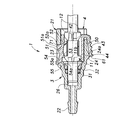
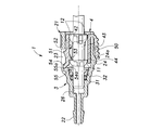
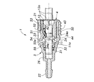
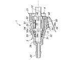
- FIG. 5 to 10 show a series of operation states in which the pipe 2 is coupled to the connector 1 and then the coupling is released.
- FIG. 5 shows a state before the pipe 2 is joined
- FIGS. 6 to 8 show a state until the joining of the pipe 2 is completed
- FIGS. 9 and 10 show that the joining of the pipe 2 is released. The state until is shown.
- the locking pieces 42 and 42 of the lock member are in an initial state in which they are not elastically deformed, and the rear surface 51a (see FIG. 6) is in contact with the front surface 52a (see FIG. 6) of the contact portion 52 that defines the rear edge of the opening 23 of the connector 1.
- the movement of the lock member 4 is restricted, and the lock member 4 is stably held at the retracted position shown in FIG.
- the operation pieces 43 and 43 of the lock member are also in an initial state in which they are not elastically deformed, and their tips are in contact with the base portion on the rear end side of the pressing portion 24 projecting from the connector body 3. .
- the pipe 2 inserted into the insertion hole 26 of the connector main body 3 has an inclined front surface of the rib portion 11 b in the flange portion 11 inside the locking pieces 42 and 42 in the lock member 4. It moves forward in a state of sliding contact with the inclined rear surface of the locking claw 53. As a result, the lock member 4 slides forward, and the locking pieces 42 and 42 are pressed from the inside by the flange portion 11 of the pipe 2 and gradually elastically deform and expand outward.
- the locking pieces 42, 42 of the lock member 4 have a pressing portion in which a tip portion 54 bent obliquely toward the outside (upper side in FIG. 5) defines the front edge of the opening 23 of the connector 1.
- a tip portion 54 bent obliquely toward the outside upper side in FIG. 5
- the upper surface 55a of the pressing portion 55 is inclined obliquely upward toward the front at substantially the same angle as the lower surface 54a of the distal end portion 54.
- the locking pieces 42, 42 are elastically deformed so that the distal end side (free end side) rides on the pressing portion 55.
- the operation pieces 43 and 43 of the lock member 4 are in a state in which the front end portion 61 is in sliding contact with the rear surface 24a of the pressing portion (second pressing portion) 24 inclined obliquely downward toward the front. Move forward. Thereby, the operation pieces 43 and 43 are elastically deformed so that the front end side (free end side) rides on the pressing portion 24.
- the lock member 4 is configured to slide toward the pressing portion 55 by being pressed by the pipe 2 when the pipe 2 is inserted into the connector main body 3. Only by inserting the connector body 3 into the connector body 3, the locking pieces 42, 42 can be elastically deformed in the released state, and there is an advantage that good operability can be obtained.
- the operation pieces 43 and 43 that have been on the pressing portion 24 are slid on the rear surface 24 a of the pressing portion 24 of the connector main body 3 as the lock member 4 moves rearward. It will be in contact. Thereby, the elastic recovery force of the operation pieces 43 and 43 acts so that the lock member 4 may be moved back like the locking pieces 42 and 42. As shown in FIG. 7, the deformation of the operation pieces 43, 43 is not completely recovered even after the elastic deformation of the locking pieces 42, 42 is recovered. Therefore, after that, as shown in FIG. 8, the lock member 4 moves backward to the retracted position where the elastic deformation of the operation pieces 43 and 43 is recovered. Thereby, the coupling of the pipe 2 to the connector 1 is completed.
- the connector 1 having the above configuration is configured to elastically deform from a fixed state to a released state when the locking pieces 42 and 42 of the lock member 4 that has been slid are pressed by a pressing portion 55 formed on the connector body 3. Therefore, when the pipe 2 is connected, the connection state is stably maintained, and when the pipe 2 is released, the user does not need a large operating force to pull out the pipe 2 and has good operability. There is an advantage that it can be obtained.
- the free end side of the locking pieces 42, 42 rides on the inclined upper surface 55 a of the pressing portion 55 of the connector 1, so that the inner locking claw 53 is connected to the flange portion of the pipe 2. 11, and the elastic recovery force of the locking pieces 42 and 42 acts as a force for sliding the lock member 4 backward, so that the user can greatly slide the lock member 4 backward. Good operability can be obtained without the need for operating force. Furthermore, when the lock member 4 slides, the free end side of the operation pieces 43, 43 rides on the inclined rear surface 24a of the pressing portion 55 of the connector 1, so that the elastic recovery force of the operation pieces 43, 43 is also locked.
- the pipe connection target is not limited to the hose connected to the hose connection part as described above.
- the hose connection part is not provided, and as a part of a housing of a device that can be a pipe connection target.
- a connector body may be provided.
Landscapes
- Engineering & Computer Science (AREA)
- General Engineering & Computer Science (AREA)
- Mechanical Engineering (AREA)
- Quick-Acting Or Multi-Walled Pipe Joints (AREA)
Abstract
Description
また、上記第2の発明によれば、ロック部材がスライド操作された際に、係止片の自由端側(すなわち、パイプを係止する部位)をパイプから離間させるように容易に弾性変形させることができる。また、係止片の弾性回復力が、係止片を固定状態とする側にロック部材をスライドさせる力として作用するため、使用者はロック部材のスライドに大きな操作力を必要とせずに良好な操作性が得られる。
また、上記第3の発明によれば、係止片が固定状態にある場合には、第1規制部によってパイプの離脱方向への移動が規制された状態で、第2規制部によって係止片の弾性変形が規制される(すなわち、第1規制部の規制が解除されることが防止される)ため、パイプの連結状態がより安定的に保持される。
また、上記第4の発明によれば、操作片の弾性回復力が、係止片を固定状態とする側にロック部材をスライドさせる力として作用するため、使用者はロック部材のスライドに大きな操作力を必要とせずに良好な操作性が得られる。また、操作片の弾性回復力は、係止片が初期状態となる位置へとロック部材を常に戻すように作用するため、係止片が弾性変形した状態で維持されてしまうことにより発生するクリープ現象を防止することができる。
また、上記第5の発明によれば、ロック部材の係止片と操作片とを、簡易かつコンパクトな構成により実現することができる。
また、上記第6の発明によれば、コネクタ本体およびロック部材の構成を複雑化することなく、係止片を解除状態に弾性変形させることができる。
また、上記第7の発明によれば、コネクタ本体の構成を複雑化することなく、第1押圧部を容易に実現することができる。
2 パイプ
3 コネクタ本体
4 ロック部材
11 鍔部
12 凸部
13 ホース接続部
21 筒状部
22 ホース接続部
23 開口
24 押圧部
26 挿入孔
41 リング部
42 係止片
43 操作片
44 ガイド片
50 被挟持部
51 外側係止爪
52 当接部
53 内側係止爪
54 先端部
55 押圧部
61 先端部
71 当接面
Claims (7)
- パイプを連結対象に連結するためのパイプ連結用コネクタであって、
前記パイプが挿脱されるコネクタ本体と、
前記コネクタ本体にスライド自在に保持され、前記パイプを係止片によって固定するロック部材と、
前記ロック部材のスライド操作に供される操作片と
を備え、
前記係止片は、前記ロック部材がスライド操作された際に、前記コネクタ本体に形成された第1押圧部に押圧されることで、前記パイプを固定する固定状態から、当該パイプを解放する解除状態に弾性変形することを特徴とするパイプ連結用コネクタ。 - 前記係止片は、前記ロック部材の基部から前記パイプの挿入方向に延設され、その自由端側が前記コネクタ本体の第1押圧部に乗り上げることにより、前記解除状態に弾性変形することを特徴とする、請求項1に記載のパイプ連結用コネクタ。
- 前記係止片は、前記固定状態にある場合に前記パイプの離脱方向への移動を規制する第1規制部と、前記コネクタ本体に形成された当接部に当接することで、前記固定状態から前記解除状態への弾性変形を規制する第2規制部とを有することを特徴とする、請求項1に記載のパイプ連結用コネクタ。
- 前記操作片は、前記ロック部材の基部から前記パイプの挿入方向に延設されるとともに、前記係止片が解除状態にある場合に、その自由端側が前記コネクタ本体に形成された第2押圧部に乗り上げることにより弾性変形することを特徴とする、請求項1に記載のパイプ連結用コネクタ。
- 前記ロック部材の基部はリング状を呈し、
前記係止片と前記操作片とは、前記ロック部材の基部の周方向に互いに離間されて延設されるとともに、当該係止片は、前記コネクタ本体の内側に配置され、当該操作片は、前記コネクタ本体の外側に配置されたことを特徴とする、請求項1に記載のパイプ連結用コネクタ。 - 前記コネクタ本体には、前記係止片と係合する係合孔が設けられ、
前記係止片は、前記解除状態に弾性変形する際に、前記係合孔から前記コネクタ本体の外側に突出することを特徴とする、請求項5に記載のパイプ連結用コネクタ。 - 前記第1押圧部が、前記係合孔の開口縁に形成されたことを特徴とする、請求項6に記載のパイプ連結用コネクタ。
Priority Applications (4)
| Application Number | Priority Date | Filing Date | Title |
|---|---|---|---|
| CN201080013635.5A CN102362114B (zh) | 2009-03-23 | 2010-03-18 | 管连接用连接器 |
| KR1020117021921A KR101305856B1 (ko) | 2009-03-23 | 2010-03-18 | 파이프 연결용 커넥터 |
| EP10755631.8A EP2413013B1 (en) | 2009-03-23 | 2010-03-18 | Pipe connecting connector |
| US13/138,733 US8696037B2 (en) | 2009-03-23 | 2010-03-18 | Connector for pipe connection |
Applications Claiming Priority (2)
| Application Number | Priority Date | Filing Date | Title |
|---|---|---|---|
| JP2009070657A JP5306868B2 (ja) | 2009-03-23 | 2009-03-23 | パイプ連結用コネクタ |
| JP2009-070657 | 2009-03-23 |
Publications (1)
| Publication Number | Publication Date |
|---|---|
| WO2010109828A1 true WO2010109828A1 (ja) | 2010-09-30 |
Family
ID=42780527
Family Applications (1)
| Application Number | Title | Priority Date | Filing Date |
|---|---|---|---|
| PCT/JP2010/001951 Ceased WO2010109828A1 (ja) | 2009-03-23 | 2010-03-18 | パイプ連結用コネクタ |
Country Status (6)
| Country | Link |
|---|---|
| US (1) | US8696037B2 (ja) |
| EP (1) | EP2413013B1 (ja) |
| JP (1) | JP5306868B2 (ja) |
| KR (1) | KR101305856B1 (ja) |
| CN (1) | CN102362114B (ja) |
| WO (1) | WO2010109828A1 (ja) |
Cited By (2)
| Publication number | Priority date | Publication date | Assignee | Title |
|---|---|---|---|---|
| JP2013113090A (ja) * | 2011-11-24 | 2013-06-10 | Toyota Boshoku Corp | エアクリーナ装置及び吸気ダクト装置 |
| US20130199021A1 (en) * | 2013-03-14 | 2013-08-08 | Michael A. Jupe | Remote Cam-lock Coupling Actuator and Discharge Containment Device |
Families Citing this family (21)
| Publication number | Priority date | Publication date | Assignee | Title |
|---|---|---|---|---|
| US9528645B2 (en) * | 2010-11-19 | 2016-12-27 | Kongsberg Automotive Ab | Device for coupling a tube to a housing |
| EP2481966A1 (en) | 2011-02-01 | 2012-08-01 | Uponor Innovation AB | Clamping ring |
| JP5868207B2 (ja) * | 2012-02-15 | 2016-02-24 | 株式会社ニフコ | コネクタ |
| USD757259S1 (en) * | 2012-04-05 | 2016-05-24 | Medline Industries, Inc. | Female portion of a connector |
| US10359139B2 (en) | 2012-04-05 | 2019-07-23 | Medline Industries, Inc. | Connector |
| DE102012106925A1 (de) * | 2012-07-30 | 2014-06-12 | Contitech Schlauch Gmbh | Schnellverbindungsanordnung zur lösbaren Verbindung einer Medienleitung mit einem Stutzen |
| DE102012107463A1 (de) * | 2012-08-15 | 2014-06-12 | Contitech Schlauch Gmbh | Schnellverbindungsanordnung zur lösbaren Verbindung einer Medienleitung mit einem Stutzen |
| EP2728236B1 (de) * | 2012-11-05 | 2017-04-19 | TI Automotive (Fuldabrück) GmbH | Schnellkupplung |
| CN103217747B (zh) * | 2013-03-04 | 2015-04-29 | 中航光电科技股份有限公司 | 光纤连接器分线装置 |
| US9203199B2 (en) * | 2013-03-15 | 2015-12-01 | Aqua Products, Inc. | Waterproof separable swivel connector |
| DE102014107655B4 (de) * | 2014-05-30 | 2024-07-11 | Voss Automotive Gmbh | Steckverbinder für Fluidleitungen mit innenliegender Adapterhülse |
| JP6367619B2 (ja) * | 2014-06-27 | 2018-08-01 | 株式会社ハイレックスコーポレーション | ケーブル連結装置 |
| US9657656B2 (en) * | 2014-08-27 | 2017-05-23 | Continental Automotive Systems, Inc. | Idle air control valve for use in a small engine and having a protective shroud with valve seat |
| KR102383330B1 (ko) * | 2016-11-02 | 2022-04-05 | 현대자동차주식회사 | 퀵 커넥터 |
| US11506316B2 (en) | 2017-03-06 | 2022-11-22 | Ipex Technologies Inc. | Releasable connect/disconnect fitting connection |
| CA2960023C (en) | 2017-03-06 | 2023-08-08 | Ipex Technologies Inc. | Releasable connect/disconnect fitting connection |
| CN107816590A (zh) * | 2017-12-01 | 2018-03-20 | 重庆溯联汽车零部件有限公司 | 冷却管快速接头 |
| JP6989167B1 (ja) * | 2020-07-20 | 2022-01-05 | 株式会社ニチリン | スナップフィット係合コネクタ |
| JP2024138571A (ja) * | 2021-08-06 | 2024-10-09 | 三桜工業株式会社 | コネクタ及びソケット |
| CN116154507B (zh) * | 2023-01-03 | 2025-12-02 | 浙江珠城科技股份有限公司 | 一种鱼叉型插接分流连接器 |
| CN223563712U (zh) * | 2024-11-08 | 2025-11-18 | 温州弗锐斯建材有限公司 | 接头组件 |
Citations (2)
| Publication number | Priority date | Publication date | Assignee | Title |
|---|---|---|---|---|
| JPS62177223A (ja) * | 1986-01-28 | 1987-08-04 | Mitsubishi Heavy Ind Ltd | 炭素繊維の紡糸連続取出し方法 |
| JP3107085B2 (ja) | 1998-07-16 | 2000-11-06 | ラスムッセン ジイエムビイエイチ | 2つの流体導管路を結合する差込み継手 |
Family Cites Families (27)
| Publication number | Priority date | Publication date | Assignee | Title |
|---|---|---|---|---|
| US3569903A (en) * | 1969-08-07 | 1971-03-09 | Sealectro Corp | Coaxial connector with axial interlock |
| JPS5217128Y2 (ja) * | 1972-05-24 | 1977-04-18 | ||
| JPS5217128U (ja) | 1975-07-22 | 1977-02-07 | ||
| IT1086546B (it) * | 1977-05-23 | 1985-05-28 | Uniflex Spa | Giunto per tubi flessibili ad aggancio e sgancio rapido |
| IT8534836V0 (it) * | 1985-04-02 | 1985-04-02 | Gf Srl | Raccordo ad innesto rapido per tubi flessibili in genere |
| US4660803A (en) * | 1986-02-26 | 1987-04-28 | Suncast Corporation | Quick coupling connector for connecting flexible liquid conduits |
| JPS62177223U (ja) * | 1986-04-24 | 1987-11-11 | ||
| CN1014264B (zh) | 1988-03-17 | 1991-10-09 | 马克斯·帕斯布里希 | 可拆式管棒联接器 |
| IT1220749B (it) * | 1988-05-04 | 1990-06-21 | Uniflex Utilime Spa | Innesto rapido per la giunzione scioglibile di tubi |
| DK0401083T3 (da) * | 1989-05-29 | 1994-04-25 | Autobrevets | Indretning for tilvejebringelse af en tæt samling mellem et rør og en slange |
| AU7438891A (en) | 1991-04-29 | 1992-10-15 | Kabushiki Kaisha Harmo Sogo Kenkyujo | Tubing joint |
| DE4413346C1 (de) | 1994-04-18 | 1995-08-17 | Rasmussen Gmbh | Steckkupplung zum Verbinden zweier Fluidleitungen |
| JP2706629B2 (ja) * | 1994-12-28 | 1998-01-28 | 株式会社日本ピスコ | 管継手 |
| DE19540279A1 (de) * | 1995-10-28 | 1997-04-30 | Balfo Verwaltungs Anstalt | Anschlußstück für Profilrohre, Profilstutzen, Wellschläuche oder dergleichen Stränge |
| JPH09152078A (ja) * | 1995-11-28 | 1997-06-10 | Kunimori Kagaku:Kk | 弾性管継手 |
| JP3938798B2 (ja) * | 1996-11-20 | 2007-06-27 | 臼井国際産業株式会社 | 細径配管接続用コネクター |
| US5823508A (en) * | 1996-12-20 | 1998-10-20 | Itt Automotive, Inc. | One piece quick connect |
| JP3386406B2 (ja) * | 1999-04-28 | 2003-03-17 | 株式会社日本ピスコ | 管継手 |
| JP2000310383A (ja) * | 1999-04-28 | 2000-11-07 | Nippon Pisuko:Kk | 管継手 |
| DE60138929D1 (de) | 2000-04-19 | 2009-07-16 | Adrian Roger Poulton | Anschlussanordnung |
| FR2808862B1 (fr) * | 2000-05-10 | 2002-07-19 | Legris Sa | Dispositif de raccordement d'un embout a un organe |
| JP2002022082A (ja) * | 2000-07-05 | 2002-01-23 | Shinsei Kogyo Kk | 管継手 |
| US6467816B1 (en) * | 2001-08-21 | 2002-10-22 | Huang-Fu Huang | Water pipe joint |
| GB2387420B (en) * | 2002-02-18 | 2004-05-05 | Walterscheid Gmbh Jean | Coupling for connecting hydraulic ducts |
| JP4264937B2 (ja) * | 2003-07-09 | 2009-05-20 | Smc株式会社 | チャック及び管継手 |
| FR2863683B1 (fr) * | 2003-12-10 | 2006-02-17 | Legris Sa | Dispositif de raccordement instantane |
| GB2412416B (en) | 2004-03-22 | 2008-04-16 | Tokai Rubber Ind Ltd | Quick connector |
-
2009
- 2009-03-23 JP JP2009070657A patent/JP5306868B2/ja not_active Expired - Fee Related
-
2010
- 2010-03-18 CN CN201080013635.5A patent/CN102362114B/zh not_active Expired - Fee Related
- 2010-03-18 EP EP10755631.8A patent/EP2413013B1/en not_active Not-in-force
- 2010-03-18 US US13/138,733 patent/US8696037B2/en not_active Expired - Fee Related
- 2010-03-18 KR KR1020117021921A patent/KR101305856B1/ko not_active Expired - Fee Related
- 2010-03-18 WO PCT/JP2010/001951 patent/WO2010109828A1/ja not_active Ceased
Patent Citations (2)
| Publication number | Priority date | Publication date | Assignee | Title |
|---|---|---|---|---|
| JPS62177223A (ja) * | 1986-01-28 | 1987-08-04 | Mitsubishi Heavy Ind Ltd | 炭素繊維の紡糸連続取出し方法 |
| JP3107085B2 (ja) | 1998-07-16 | 2000-11-06 | ラスムッセン ジイエムビイエイチ | 2つの流体導管路を結合する差込み継手 |
Non-Patent Citations (1)
| Title |
|---|
| See also references of EP2413013A4 |
Cited By (3)
| Publication number | Priority date | Publication date | Assignee | Title |
|---|---|---|---|---|
| JP2013113090A (ja) * | 2011-11-24 | 2013-06-10 | Toyota Boshoku Corp | エアクリーナ装置及び吸気ダクト装置 |
| US20130199021A1 (en) * | 2013-03-14 | 2013-08-08 | Michael A. Jupe | Remote Cam-lock Coupling Actuator and Discharge Containment Device |
| US9410648B2 (en) * | 2013-03-14 | 2016-08-09 | Michael A. Jupe | Remote cam-lock coupling actuator and discharge containment device |
Also Published As
| Publication number | Publication date |
|---|---|
| US20120080880A1 (en) | 2012-04-05 |
| EP2413013A1 (en) | 2012-02-01 |
| JP5306868B2 (ja) | 2013-10-02 |
| US8696037B2 (en) | 2014-04-15 |
| CN102362114A (zh) | 2012-02-22 |
| KR20110116245A (ko) | 2011-10-25 |
| EP2413013A4 (en) | 2014-03-05 |
| CN102362114B (zh) | 2014-03-12 |
| JP2010223319A (ja) | 2010-10-07 |
| EP2413013B1 (en) | 2017-08-02 |
| KR101305856B1 (ko) | 2013-09-06 |
Similar Documents
| Publication | Publication Date | Title |
|---|---|---|
| JP5306868B2 (ja) | パイプ連結用コネクタ | |
| JP4011575B2 (ja) | クイックコネクタ | |
| CN111306388A (zh) | 用于连接软管的快速接头总成 | |
| JP6043108B2 (ja) | コネクタ | |
| CN107851934B (zh) | 具有嵌合检测功能的电气连接装置 | |
| WO2014050119A1 (ja) | コネクタ | |
| CN112152017B (zh) | 连接器 | |
| JP5613478B2 (ja) | パイプ連結用コネクタ | |
| JP2001289381A (ja) | コネクタ | |
| WO2019131372A1 (ja) | コネクタ | |
| JP2007255669A (ja) | クイックコネクタ | |
| CN114593297B (zh) | 快速连接器 | |
| JP4402498B2 (ja) | 管継手 | |
| TWM666129U (zh) | 防誤壓之連接器組及其母座連接器 | |
| JP5941772B2 (ja) | コネクタ | |
| JP2018165544A (ja) | コネクタユニット | |
| CN111448719B (zh) | 连接器 | |
| JP2012190707A (ja) | コネクタ | |
| JP6281543B2 (ja) | コネクタ | |
| CN111448720B (zh) | 连接器 | |
| JP4601996B2 (ja) | 管継手 | |
| JP5826014B2 (ja) | 管接続構造 | |
| WO2012096143A1 (ja) | パイプコネクタ | |
| JP4713094B2 (ja) | 管継手 | |
| JP6284075B2 (ja) | コネクタ |
Legal Events
| Date | Code | Title | Description |
|---|---|---|---|
| WWE | Wipo information: entry into national phase |
Ref document number: 201080013635.5 Country of ref document: CN |
|
| 121 | Ep: the epo has been informed by wipo that ep was designated in this application |
Ref document number: 10755631 Country of ref document: EP Kind code of ref document: A1 |
|
| ENP | Entry into the national phase |
Ref document number: 20117021921 Country of ref document: KR Kind code of ref document: A |
|
| NENP | Non-entry into the national phase |
Ref country code: DE |
|
| REEP | Request for entry into the european phase |
Ref document number: 2010755631 Country of ref document: EP |
|
| WWE | Wipo information: entry into national phase |
Ref document number: 2010755631 Country of ref document: EP |
|
| WWE | Wipo information: entry into national phase |
Ref document number: 13138733 Country of ref document: US |