WO2010113373A1 - 印刷方法および被印刷体 - Google Patents
印刷方法および被印刷体 Download PDFInfo
- Publication number
- WO2010113373A1 WO2010113373A1 PCT/JP2010/000409 JP2010000409W WO2010113373A1 WO 2010113373 A1 WO2010113373 A1 WO 2010113373A1 JP 2010000409 W JP2010000409 W JP 2010000409W WO 2010113373 A1 WO2010113373 A1 WO 2010113373A1
- Authority
- WO
- WIPO (PCT)
- Prior art keywords
- small
- printing
- pattern
- small printing
- ink
- Prior art date
- Legal status (The legal status is an assumption and is not a legal conclusion. Google has not performed a legal analysis and makes no representation as to the accuracy of the status listed.)
- Ceased
Links
Images








Classifications
-
- B—PERFORMING OPERATIONS; TRANSPORTING
- B41—PRINTING; LINING MACHINES; TYPEWRITERS; STAMPS
- B41M—PRINTING, DUPLICATING, MARKING, OR COPYING PROCESSES; COLOUR PRINTING
- B41M1/00—Inking and printing with a printer's forme
- B41M1/40—Printing on bodies of particular shapes, e.g. golf balls, candles, wine corks
-
- B—PERFORMING OPERATIONS; TRANSPORTING
- B41—PRINTING; LINING MACHINES; TYPEWRITERS; STAMPS
- B41F—PRINTING MACHINES OR PRESSES
- B41F17/00—Printing apparatus or machines of special types or for particular purposes, not otherwise provided for
- B41F17/001—Pad printing apparatus or machines
-
- B—PERFORMING OPERATIONS; TRANSPORTING
- B41—PRINTING; LINING MACHINES; TYPEWRITERS; STAMPS
- B41F—PRINTING MACHINES OR PRESSES
- B41F17/00—Printing apparatus or machines of special types or for particular purposes, not otherwise provided for
- B41F17/30—Printing apparatus or machines of special types or for particular purposes, not otherwise provided for for printing on curved surfaces of essentially spherical, or part-spherical, articles
- B41F17/34—Printing apparatus or machines of special types or for particular purposes, not otherwise provided for for printing on curved surfaces of essentially spherical, or part-spherical, articles on articles with surface irregularities, e.g. fruits, nuts
-
- B—PERFORMING OPERATIONS; TRANSPORTING
- B41—PRINTING; LINING MACHINES; TYPEWRITERS; STAMPS
- B41M—PRINTING, DUPLICATING, MARKING, OR COPYING PROCESSES; COLOUR PRINTING
- B41M1/00—Inking and printing with a printer's forme
- B41M1/02—Letterpress printing, e.g. book printing
-
- B—PERFORMING OPERATIONS; TRANSPORTING
- B41—PRINTING; LINING MACHINES; TYPEWRITERS; STAMPS
- B41M—PRINTING, DUPLICATING, MARKING, OR COPYING PROCESSES; COLOUR PRINTING
- B41M1/00—Inking and printing with a printer's forme
- B41M1/10—Intaglio printing ; Gravure printing
Definitions
- the present invention relates to a printing method and a printing medium, and more particularly to a printing method in which a printing surface is divided into a plurality of regions for printing, and a printing medium printed by the printing method.
- Patent Document 1 has a remarkable effect when printing a flat surface or a curved surface at a time.
- the shape of the printing medium is complicated, for example, when a recessed portion is formed in the printing medium, there is a problem that it is difficult to print in the recessed portion.
- the edge of the print area (the equator of the sphere)
- a first object of the invention is to provide a printing method capable of printing on a printing medium having a complicated shape (for example, having a concave portion).
- a second object of the present invention is to provide a printing method in which, when printing is performed in a plurality of print areas, even if a print overlap area occurs at the end of the print area, the color tone of the overlap area does not become dark. There is.
- a third object is to obtain a printing medium printed by the printing method.
- a printing surface of a printing medium is divided into a plurality of small printing surfaces, and a pattern printed on the printing surface is printed on each of the printing surfaces.
- the printing surface of the printing medium is divided into a plurality of small printing surfaces so that the respective boundaries overlap each other with a predetermined width, and the pattern printed on the printing surface is printed on the small printing material Dividing into small patterns printed on each of the surfaces; Creating a small development pattern in which the small design is developed on a plane; The amount of ink in a predetermined width of the boundary along the small developed pattern on the small printing surface corresponding to each of the small printing original plates corresponding to each of the plurality of small printing surfaces is determined by the predetermined amount of the boundary.
- a step of placing ink so as to be less than the amount of ink in a range excluding the width of A step of pressing a small printing blanket corresponding to each of the plurality of small printing surfaces against a corresponding small printing original plate to transfer the ink to each of the small printing blankets; Printing the pattern on the printing surface by pressing the plurality of small printing blankets against the corresponding small printing surface, and printing the small pattern on the small printing surface; It is characterized by having.
- the printing surface of the printing medium is divided into a plurality of small printing surfaces, and the pattern printed on the printing surface is divided into small patterns printed on each of the printing surfaces.
- Process Creating a small development pattern in which the small design is developed on a plane; A step of placing ink along the small development pattern on the small printing surface corresponding to each of the small printing original plates corresponding to each of the plurality of small printing surfaces; A step of pressing a small printing blanket corresponding to each of the plurality of small printing surfaces against a corresponding small printing original plate to transfer the ink to each of the small printing blankets; Printing the pattern on the printing surface by pressing the plurality of small printing blankets against the corresponding small printing surface and printing the small pattern on the small printing surface; Have The plurality of small printing blankets are pressed against the small printing original plate in parallel with the normal line of the corresponding small printing original plate, and each of the small printing blankets is parallel to the average normal line of the corresponding small printing surface. It is characterized by being pressed against the small print surface.
- the printing surface of the printing material is divided into a plurality of small printing surfaces so that the respective boundaries overlap each other with a predetermined width, and the pattern printed on the printing surface is printed on the small printing material Dividing into small patterns printed on each of the surfaces; Creating a small development pattern in which the small design is developed on a plane; The amount of ink in a predetermined width of the boundary along the small developed pattern on the small printing surface corresponding to each of the small printing original plates corresponding to each of the plurality of small printing surfaces is determined by the predetermined amount of the boundary.
- a step of placing ink so as to be less than the amount of ink in a range excluding the width of A step of pressing a small printing blanket corresponding to each of the plurality of small printing surfaces against a corresponding small printing original plate to transfer the ink to each of the small printing blankets; Printing the pattern on the printing surface by pressing the plurality of small printing blankets against the corresponding small printing surface and printing the small pattern on the small printing surface; Have The plurality of small printing blankets are pressed against the small printing original plate in parallel with the normal line of the corresponding small printing original plate, and each of the small printing blankets is parallel to the average normal line of the corresponding small printing surface. It is characterized by being pressed against the small print surface.
- any one of (1) to (4) the positions of each of the plurality of small printing surfaces are stored, and the small printing corresponding to each of the plurality of small printing surfaces is performed.
- a blanket for printing is sequentially gripped, and a step of printing the picture is performed using a multi-axis robot that presses the gripped small printing blanket against the small print surface corresponding thereto.
- the positions of each of the plurality of small printing surfaces are stored, and the small printing corresponding to each of the plurality of small printing surfaces is performed. Sequentially gripping the blanket for printing, and using the multi-axis robot that presses the gripped blanket for printing on the small print surface corresponding to the gripping blanket,
- the small printing surface is a side surface or a bottom surface of a recess recessed into the printed material;
- the small printing blanket corresponding to the side surface or the bottom surface can freely enter the concave portion.
- the position of each of the plurality of small printing surfaces is stored, and the small printing corresponding to each of the plurality of small printing surfaces
- the small printing surface is a side surface or a bottom surface of a recess recessed into the printed material;
- a gripping portion of the multi-axis robot that grips the small printing blanket corresponding to the side surface or the bottom surface can enter the concave portion.
- the printing surface of the printing medium is divided into a plurality of small printing surfaces, and a pattern printed on the printing surface is applied to each of the small printing surfaces.
- the printing surface of the printing material is divided into a plurality of small printing surfaces so that the respective boundaries overlap each other with a predetermined width, and the pattern printed on the printing surface is printed on the small printing material Dividing into small patterns printed on each of the surfaces; Creating a small development pattern in which the small design is developed on a plane; The amount of ink in a predetermined width of the boundary along the small developed pattern on the small printing surface corresponding to each of the small printing original plates corresponding to each of the plurality of small printing surfaces is determined by the predetermined amount of the boundary.
- Have The step of printing the pattern uses a lifting device that moves up and down with respect to the substrate on which the substrate is placed, The lifting device grips the small printing blanket corresponding to the plurality of small printing surfaces, and presses the small printing blanket against the small printing surface corresponding thereto.
- the step of printing the pattern uses a lifting device that moves up and down with respect to the substrate on which the substrate to be printed is placed.
- the lifting device grips the small printing blanket corresponding to the small printing surface, and The portion of the blanket to which the ink has not been transferred is pressed against the substrate, whereby the portion of the small printing blanket to which the ink has been transferred is pressed against the corresponding surface to be printed.
- the step of printing the pattern uses a lifting device that moves up and down with respect to the substrate on which the substrate to be printed is placed, When printing a part of the pattern on a small printing surface located on a side surface of the printing medium, the lifting device grips the small printing blanket corresponding to the small printing surface, and By pressing a portion of the blanket to which the ink has not been transferred against the substrate, the portion of the small printing blanket to which the ink has been transferred is pressed against the corresponding surface to be printed.
- the range of the substrate on which the portion of the small printing blanket to which the ink is not transferred is pressed is lower than the range of the substrate on which the printing body is placed in the lifting direction of the lifting device. It is located.
- the substrate to be printed according to the present invention is a substrate to be printed by any one of the printing methods (1), (2), (3), (4), (8) or (9). It has a surface.
- the printing method according to the present invention prints a pattern on a printing surface using a blanket for small printing corresponding to a small pattern obtained by dividing the pattern, printing on a printed body having a complicated shape is possible.
- the pressing directions of the plurality of small printing blankets are made parallel to each other, the pressing operation is simplified, and the apparatus used for the pressing can be simplified.
- a plurality of small printing blankets may be pressed separately one by one, or several of the plurality of small printing blankets (individually different shapes) may be simultaneously pressed. , It may be pressed to a plurality of locations.
- the step of printing a pattern uses a lifting device that moves up and down (moves up and down) with respect to the substrate on which the printing medium is placed.
- a plurality of small printing blankets may be individually attached to the lifting device one by one, or any number of the plurality of small printing blankets (individually different shapes). You may attach these to several places of a raising / lowering apparatus.
- the substrate or the lifting device is provided with horizontal moving means (moving in the X and Y directions). .
- the lifting means is lowered. Further, the horizontal relative position between the substrate and the lifting device may be changed in synchronization with the lowering of the lifting means.
- the printing medium is moved in the horizontal direction (X direction and Y direction)
- the lifting device is moved in the horizontal direction (X direction and Y direction)
- both are moved in the horizontal direction (X direction and Y direction). Direction).
- the lifting device presses the portion of the small printing blanket where the ink is not transferred to the substrate, The portion of the small printing blanket to which the ink has been transferred is pressed against the corresponding small surface to be printed. (So-called overhang side surface) can be printed.
- horizontal moving means moving in the X direction and Y direction installed on the substrate or the lifting device are used.
- the lifting means When the lifting means is lowered to a predetermined vertical position (including when the small printing blanket is pressed against the substrate by a predetermined amount), the lifting device may be moved closer to the printing medium (by pressing). Also good).
- the horizontal movement means may bring the lifting / lowering device closer to the printing medium in the horizontal direction (may be pressed).
- the range of the substrate to which the portion of the small printing blanket where the ink is not transferred is pressed is lower by one step in the lifting direction of the lifting device than the range of the substrate on which the printing medium is placed. Therefore, when the small printing blanket is pressed to such a lowered range, the surface of the portion where the ink of the small printing blanket is transferred tends to deform (expand) in a direction parallel to the surface of the substrate. The printing accuracy on the small print surface (side surface) is improved.
- the printing medium according to the present invention has a printing surface printed by a printing method that exhibits any of the effects (i) to (ix), the printed material has a complicated shape, An exact pattern is printed in whole or in part.
- FIG. 5 is a flowchart for explaining a printing method according to the first embodiment of the invention.
- the top view which shows typically the point which divides
- FIG. 7 is a plan view schematically showing an enlarged example of the arrangement of halftone dots in a small development pattern in the printing method shown in FIG. 6.
- FIG. 7 is a plan view schematically showing an enlarged example of the arrangement of halftone dots in a small development pattern in the printing method shown in FIG. 6.
- FIG. 7 is a plan view schematically showing an enlarged print overlapping range in the printing method shown in FIG. 6.
- 10 is a flowchart for explaining a printing method according to a fourth embodiment of the invention.
- Sectional drawing shown for every printing process explaining the printing method shown in FIG. Sectional drawing shown for every printing process explaining the printing method shown in FIG.
- Sectional drawing shown for every printing process explaining the printing method shown in FIG. Sectional drawing shown for every printing process explaining the printing method shown in FIG.
- Sectional drawing explaining the variation of the printing method shown in FIG. Sectional drawing explaining the variation of the printing method shown in FIG. Sectional drawing explaining the variation of the printing method shown in FIG. Sectional drawing which shows typically the to-be-printed body which concerns on Embodiment 5.
- FIG. 10 is a plan view schematically showing an enlarged overlapping range of printing in a printing method according to Embodiment 6 of the present invention.
- FIG. 1 is a flowchart
- FIGS. 2 to 4 are cross-sectional views for each printing process.
- FIGS. 2 to 4 schematically show partly exaggerated, and the present invention is intended to illustrate the shape of the printed body and the form (shape, distribution, etc.) of the pattern (ink). It is not limited.
- symbol may be abbreviate
- the printing surface 10 (position 11 to position 18) of the printing medium 100 is replaced with a plurality of small printing surfaces 1a, 1b1, 1b2,... 1f (hereinafter referred to as “small printing surfaces”). 1 ”) (S1 shown in FIG. 1), a pattern 20 (not shown) to be printed on the printing surface 10 is printed on each of the small printing surfaces 1 by small patterns 2a, 2b1, 2b2... 2f (hereinafter each referred to as “small picture 2”) (S2 shown in FIG. 1). Then, small developed patterns 3a, 3b1, 3b2,... 3f (hereinafter referred to as “small developed patterns 3”) are created (S3 shown in FIG. 1).
- the small printing original plates 30a, 30b,... 30f (hereinafter referred to as “small printing original plate 30”) corresponding to the small printing surfaces 1 respectively.
- Ink is placed along the small developed pattern 3 on the printing surface 1 (S4 shown in FIG. 1).
- ink is placed on the small printing original plate 30b along the small unfolded pattern 3b1 and the small unfolded pattern 3b2.
- the method of placing the ink is not limited, and ink may be placed on the convex portion of the relief plate on which the small development pattern 3 is formed or the concave portion of the intaglio plate, or printing on a flat plate (inkjet printer, screen printing,
- the ink may be applied by gravure printing, offset printing, or the like.
- the small printing blankets 40a, 40b,... 40f (hereinafter referred to as “small printing blankets 40”) corresponding to the small printing surfaces 1 respectively correspond to it.
- the ink is pressed onto the small printing original plate 30 to be transferred, and the ink is transferred to each small printing blanket 40 (S5 shown in FIG. 1). At this time, it is pressed parallel to the normal line of the small printing original plate 30.
- the small printing blanket 40 may be pressed against the corresponding small printing original plate 30 using a multi-axis robot.
- the small printing blanket 40 that has been pressed and separated after pressing is applied to the small printing blanket patterns 4 a, 4 b,. Ink adheres along the blanket pattern 4).
- the small printing blanket 40a is pressed against the small print surface 1a to which the small printing blanket 40a corresponds, and the small pattern 2a is printed thereon (S6 shown in FIG. 1).
- the small printing blanket 40a is held by an arm 50 of a multi-axis robot (not shown), accurately positioned, and pressed parallel to the normal line at the approximate center of the small printing surface 1a (indicated by an arrow). ing.
- the small printing blanket 40b is pressed against the small printing surface 1b1 and the small printing surface 1b2 to which the small printing blanket 40b corresponds, and the small picture 2b1 and the small picture 2b2 are printed thereon (FIG. 1). S6).
- the small printing blanket 40b is gripped and accurately positioned by an arm 50 of a multi-axis robot (not shown), and the normal line at the approximate center of the small print surface 1b1 and the normal at the approximate center of the small print surface 1b2. It is pressed parallel to one of the normals to the line, or parallel to the line located in the middle of both normals (indicated by arrows).
- the small printing blanket 40c is pressed against the small print surface 1c to which the small printing blanket 40c corresponds, and the small pattern 2c is printed thereon (S6 shown in FIG. 1).
- the small printing blanket 40c is held by an arm 50 of a multi-axis robot (not shown), enters the concave portion 101 of the printing medium 100, is accurately positioned, and is a normal line at the approximate center of the small printing surface 1c. It is pressed parallel to (indicated by the arrow).
- the tip of the arm 50 that grips the small printing blanket 40c penetrates into the recess 101, but the present invention is not limited to this, and the small printing blanket is not limited thereto.
- a part (upper part in the drawing) of 40 c may be gripped so that the tip of the arm 50 does not enter the recess 101.
- the small printing blanket 40d is pressed against the small printing surface 1c to which the small printing blanket 40d corresponds, and the small pattern 2c is printed thereon (S6 shown in FIG. 1).
- the small printing blanket 40d is held by the arm 50 of a multi-axis robot (not shown), enters the concave portion 101 of the printing medium 100, is accurately positioned, and is a normal line at the approximate center of the small printing surface 1d. It is pressed parallel to (indicated by the arrow).
- the small printing blankets 40e and 40f are pressed against the small print surfaces 1e and 1f corresponding to the blankets 40e and 40f, and the small patterns 2e and 2f are printed thereon. Therefore, the pattern 20 is printed on the printing surface 10 of the printing medium 100 by printing such a series of small patterns 2. At this time, the small pattern 2 is accurately positioned by the arm 50 of the multi-axis robot, and the recess 101 is also printed.
- the small printing blanket 40 is individually held and the small pattern 2 is printed separately, but a plurality of small patterns 2 are printed almost simultaneously using a plurality of arms. Also good. Further, the order of printing the small pattern 2 is not limited.
- the present invention is not limited to using a multi-axis robot.
- a means having a positioning function and a pressing function may be used, or a positioning mechanism may be provided on the small printing blanket 40 or the like and pressed manually.
- FIG. 5 is a cross-sectional view schematically showing a substrate to be printed according to Embodiment 2 of the present invention.
- the same parts as those in the first embodiment are denoted by the same reference numerals, and a part of the description is omitted.
- the printing medium 200 is the same as the printing medium 100 on which the design 20 is printed by the printing method described in the first embodiment. That is, small patterns 2c, 2d, and 2e, which are part of the pattern 20, are also printed on the recess 101.
- FIGS. 6 to 8 illustrate a printing method according to Embodiment 3 of the present invention.
- FIG. 6 is a plan view schematically showing a procedure for dividing a pattern, and halftone dots in the small developed pattern of FIG.
- FIG. 8 is a plan view schematically showing an enlarged print overlapping range.
- FIGS. 6 to 8 are schematically shown, and the present invention is not limited to the illustration of the shape of the printing medium and the form (shape, distribution, etc.) of the halftone dots.
- the same reference numerals are given to the same or equivalent parts as in the first embodiment, and a part of the description is omitted.
- the printing surface 10 of the printing material 100 is divided into a plurality of small printing surfaces... 1c, 1d, 1e... So that the respective boundaries overlap each other with a predetermined width.
- small patterns 20c, 2d, 2e,..., 2b, 2d, 2e,. (According to S2 shown in FIG. 1).
- small unfolded patterns... 3c, 3d, 3e... Developed by developing each of the small patterns... 2c, 2d, 2e.
- Ink is put along.
- a boundary range 3cd equivalent to a predetermined width in contact with the small development pattern 3d of the small development design 3c and a boundary range 3dc equivalent to a predetermined width in contact with the small development design 3c of the small development design 3d are placed in an overlapping range 5cd.
- the amount of ink is smaller than the amount of ink placed in the inner range 3cc obtained by removing the overlapping range 5cd from the range equivalent to the enlarged small developed pattern 3bcd (see FIG. 7A).
- a boundary range 3cd equivalent to a predetermined width in contact with the small development pattern 3d of the small development pattern 3c and a small development of the small development pattern 3e are in a range equivalent to the small development pattern 3d.
- Ink is placed along a range equivalent to the enlarged and small developed pattern 3cde obtained by adding a boundary range 3ed equivalent to a predetermined width in contact with the pattern 3d. Then, the amount of ink placed in the overlapping range 5cd, the boundary range 3de equivalent to the predetermined width in contact with the small expanded pattern 3e of the small expanded pattern 3d, and the predetermined width in contact with the small expanded pattern 3d of the small expanded pattern 3e are equal.
- the amount of ink placed in the overlapping range 5de combined with the boundary range 3ed is smaller than the amount of ink placed in the inner range 3dd excluding the overlapping range 5cd and the overlapping range 5de from the range equivalent to the enlarged and small developed pattern 3cde. (See FIG. 7B).
- the number of halftone dots in the overlapping range 5cd is smaller than the number of halftone dots in the inner range 3cc and the inner range 3dd.
- the distribution of halftone dots (density per unit area) in the overlapping range 5cd gradually decreases as the distance from the inner range 3cc or the inner range 3dd increases.
- the halftone dot size in the overlapping range 5cd is smaller than the halftone dot size in the inner range 3cc and the inner range 3dd.
- the size of the halftone dot in the overlapping range 5cd gradually decreases as the distance from the inner range 3cc or the inner range 3dd increases.
- the ink is transferred to the small printing blankets... 40c, 40d, 40e. -Adhere the ink along (according to S5 shown in FIG. 1).
- the small printing blanket... 40c, 40d, 40e... Is pressed against the corresponding small printed surface... 1c, 1d, 1e. 2d, 2e... Are printed (according to S6 shown in FIG. 1).
- the predetermined width of the boundary between the small picture 2c and the small picture 2d overlaps each other, the predetermined width of the boundary between the small picture 2d and the small picture 2e overlaps each other, and the amount of ink in the overlapping range is equal to the overlapping range. Since it is less than the amount of ink in the excluded inner range, the pattern in the overlapping range does not become dark (see FIG. 8).
- the amount of ink placed in a range equivalent to the overlapping range 5cd with the small developed image 3d is reduced to “ ⁇ ”%, while in the small printing original plate 30d, the small developed image 3c is reduced. If the amount of ink placed in the range equivalent to the overlapping range 5cd with the above is reduced to “100- ⁇ ”%, the pattern in the overlapping range 5cd will not become darker or thinner, and the aesthetics will be impaired. There is nothing.
- FIG. 9 to 16 illustrate a printing method according to the fourth embodiment of the present invention.
- FIG. 9 is a flowchart
- FIGS. 10 to 13 are cross-sectional views for each printing process
- FIGS. It is sectional drawing which shows the variation of the printing method.
- FIGS. 10 to 16 schematically show partly exaggerated, and the present invention is intended to illustrate the shape of the printed body and the form (shape, distribution, etc.) of the pattern (ink). It is not limited.
- symbol may be abbreviate
- the printing method according to the fourth embodiment includes a step (S1) of dividing the printing surface 410 of the printing medium 400 into a plurality of small printing surfaces; A step (S2) of dividing the pattern to be printed on the printing surface into small patterns to be printed on each of the small printing surfaces; Creating a small unfolded pattern in which each small pattern is developed on a plane (S3); A step (S4) of placing ink on a small printing original corresponding to each of the small printing surfaces along a small development pattern on the small printing surface corresponding to each small printing surface (S4); A step (S5) of transferring the ink to each small printing blanket by pressing a small printing blanket corresponding to each of the small printing surfaces against the corresponding small printing original plate; There is a step (2 of S6) of pressing a small printing blanket against a small printing surface corresponding to the small printing blanket by using an elevating means and printing a small picture there.
- the printing surface 410 (position 411 to position 416) of the printing medium 400 is a plurality of small printing surfaces 401a, 401b1, 401b2, 401c, 401d (hereinafter each referred to as “small printing surface 401”). 9) (S1 shown in FIG. 9), and a pattern 420 (not shown) to be printed on the printing surface 410 is printed on each of the small printing surfaces 401. , 402c, 402d (hereinafter, each may be referred to as “small picture 402”) (S2 shown in FIG. 9). Then, small development patterns 403a, 403b1, 403b2, 403c, and 403d (hereinafter may be referred to as “small development patterns 403”) are created (S3 shown in FIG. 9). ).
- small printing original surfaces 430a, 430b, 430c, and 430d (hereinafter sometimes referred to as "small printing original plate 430") corresponding to the small printing surfaces 401 respectively.
- Ink 404 is placed along the small developed pattern 403 in 401 (S4 shown in FIG. 9).
- the method of placing the ink 404 is not limited.
- the ink may be placed on the convex portion of the relief plate or the concave portion of the intaglio plate on which the small development pattern 403 is formed, or printed on a flat plate (inkjet printer, screen printing,
- the ink may be applied by gravure printing, offset printing, or the like.
- the small printing blankets 440a, 440b, 440c, and 440d corresponding to the small printing surfaces 401 correspond to the small printing corresponding thereto.
- the ink 404 is pressed onto the original plate 430 to transfer the ink 404 to each small printing blanket 440 (S5 shown in FIG. 9).
- the small printing blanket 440 and the small printing surface 401 corresponding to the small printing blanket 440 are pressed against each other, and the small picture 402 is printed there (S6-2 shown in FIG. 9).
- each of the small print surfaces 401 will be described in detail.
- ink 404c is placed along the small developed pattern 403c on the small printing original plate 430c corresponding to the small print surface 401c (S4 shown in FIG. 9), and the small printing blanket 440c is applied to the small printing original plate. It is pressed against 430c (S5 shown in FIG. 9). That is, the small printing blanket 440c is deformed into a planar shape, and the ink 404c is transferred to the surface thereof.
- the blanket 440c for small printing has a substantially spindle shape (substantially arc shape or substantially parabolic shape) corresponding to the shape of the small print surface 401c that is a concave portion when not pressed, and its lowest point Corresponds to the approximate center of the small development pattern 403c.
- the printing object 400 is placed on the placement surface 491 of the substrate 490.
- the small printing blanket 440c is disposed immediately above the corresponding small printing surface 401c, and is pushed down along the normal direction (vertical direction in FIG. 11) of the mounting surface 491.
- the small printing blanket 440c is pressed downward. For this reason, since the small printing blanket 440c is deformed so as to expand toward the surface of the small print surface 401c, the ink 404c is transferred to the surface and the small pattern 402c is printed (S6 shown in FIG. 9). 2).
- the present invention is not limited to the device for pressing down (pressing), and can be aligned with the small printing surface 401c in the horizontal direction, and can be moved up and down by gripping the small printing blanket 440c. Anything is acceptable.
- the ink 404b1 and the ink 404b2 are placed on the small printing original plate 430b corresponding to the small printing surface 401b1 and the small printing surface 401b2 along the small development pattern 403b1 and the small development pattern 403b2 (FIG. 9).
- S4 the small printing blanket 440b is pressed against the small printing original plate 430b (S5 shown in FIG. 9). That is, the small printing blanket 440b is deformed into a flat shape, and the inks 404b1 and 4b2 are transferred to the surface thereof.
- the small printing blanket 440b has a substantially arc-shaped cross section (in a form in which the cylinder is halved), and its lowest point is an intermediate point between the small developed pattern 403b1 and the small developed picture 403b2. Is almost the same.
- the printing object 400 is placed on the placement surface 491 of the substrate 490.
- the small printing blanket 440b is disposed immediately above the small printing surface 401b1 and the small printing surface 401b2 to which the small printing blanket 440b corresponds, and is pushed down along the normal direction (vertical direction in FIG. 12) of the mounting surface 491.
- the small printing blanket 440b is pressed downward.
- the small printing blanket 440b is deformed so as to be adapted to the small printing surface 401b1 and the small printing surface 401b2, and the ink 404b1 and the ink 404b2 are transferred to the surface, and the small pattern 402b1 and the small pattern 402b2 are printed. (2 of S6 shown in FIG. 9).
- the device for pressing down (pressing) is not limited.
- ink 404a is placed along a small developed pattern 403a on a small printing original plate 430a corresponding to the small print surface 401a (S4 shown in FIG. 9), and a small printing blanket 440a is placed on the small printing original plate. It is pressed against 430a (S5 shown in FIG. 9). That is, the small printing blanket 440c is deformed into a planar shape, and the ink 404c is transferred to the surface thereof. At this time, in the non-pressed state, the small printing blanket 440a has a substantially parabolic cross section, and its apex (lowest point) 441a is at a position away from the small developed pattern 403a (deviation).
- apex (lowest point) 441a is at a position away from the small developed pattern 403a (deviation).
- the printing medium 400 is placed on the placement surface 491 of the substrate 490.
- the placement surface 491 is one step higher than the surrounding contact surface 492.
- the apex 441a of the small printing blanket 440a is arranged at a position horizontally separated from the corresponding small printing surface 401a, and along the normal direction (vertical direction in FIG. 13) of the mounting surface 491. , Pushing down.
- the small printing blanket 440 a is pressed against the contact surface 492.
- the small printing blanket 440c is deformed so that the surface away from the vertex 441a expands in the substantially horizontal direction, and therefore the small printing blanket 440c is pressed against the small print surface 401a. That is, the ink 404a transferred to the small printing blanket 440c is transferred to the small print surface 401a, and the small pattern 402a is printed (S6-2 shown in FIG. 9).
- the contact surface 492 is one step lower than the mounting surface 491, the surface to which the ink 404a of the small printing blanket 440c is transferred expands in parallel with the normal direction of the small printing surface 401a.
- the contact surface 492 and the placement surface 491 are parallel and have a step, but the contact surface 492 is inclined so as to become lower as the contact surface 492 is closer to the placement surface 491 (step portion). Also good.
- the small print surface 401d is in an “overhang” state with the upper side protruding, but a small pattern 402d is printed in the same manner as the small print surface 401a (“a” added to the reference numeral). Is replaced with "d”).
- the surface of the contact surface 492 on which the small printing blanket 440d abuts is inclined so as to be closer to the placement surface 491 (stepped portion), and the surface onto which the ink 404d of the small printing blanket 440d is transferred.
- FIG. 14 shows a variation of the printing method of the small picture 402b1 and the small picture 402b2 shown in FIG.
- ink 404b1 and ink 404b2 are placed on the small printing original plate 430b corresponding to the small printing surface 401b1 and the small printing surface 401b2 along the small development pattern 403b1 and the small development pattern 403b2 (FIG. 9).
- the small printing blanket 451b is pressed against the small developed pattern 403b1
- the small printing blanket 452b is pressed against the small developed picture 403b2 (S5 shown in FIG. 9).
- the small printing blankets 440b and 442b are deformed into a planar shape, and the inks 404b1 and 404b2 are transferred to the surfaces thereof.
- the small printing blanket 440b has a substantially arc-shaped cross section (a form in which the cylinder is halved), and its lowest point coincides with the center of the small developed pattern 403b1, and
- the blanket 452b is substantially arc-shaped in cross section (in a form in which the cylinder is halved), and the lowest point thereof coincides with the center of the small development pattern 403b2.
- the printing object 400 is placed on the placement surface 491 of the substrate 490.
- the small printing blanket 440b and the small printing blanket 452b are mounted on a common lifting device (not shown) so that they are directly above the corresponding small printing surface 401b1 and the small printing surface 401b2, respectively. It is pushed down along the normal direction of the mounting surface 491 (vertical direction in FIG. 14).
- the small printing blankets 451b and 442b are pressed downward.
- the small printing blanket 451b and the small printing blanket 452b are deformed so as to be adapted to the small printing surface 401b1 and the small printing surface 401b2, respectively, and the ink 404b1 and the ink 404b2 are transferred onto the surface, and the small picture 402b1 and A small pattern 402b2 is printed (2 of S6 shown in FIG. 9).
- the device for pressing down (pressing) is not limited.
- the ink 404b1 and the ink 404b2 are placed on the small printing original plate 430b.
- the present invention is not limited to this, and the ink 404b1 and the ink 404b2 may be placed on separate small printing original plates 430b.
- the small printing blanket 451b and the small printing blanket 452b are attached to a common lifting device and pressed against the printing medium 400 at the same time.
- the present invention is not limited to this, and the small printing blanket 451b.
- the small printing blanket 452b may be separately attached and one of them may be pressed first.
- FIG. 15 shows a variation in which a small picture 402d is printed on a small print surface 401d.
- a small printing original plate 430ad corresponding to the small print surface 401d, ink 404d is placed along the small developed pattern 403d (S4 shown in FIG. 9), and a small printing blanket 440d is placed on the small printing original plate 430d. (S5 shown in FIG. 9). That is, the small printing blanket 440c is deformed into a planar shape, and the ink 404c is transferred to the surface thereof.
- the substrate 400 is placed on the placement surface 491 of the substrate 490.
- the placement surface 491 is one step higher than the surrounding contact surface 492.
- the apex 441d of the small printing blanket 440d is arranged at a position horizontally separated from the corresponding small printing surface 401d and pushed down along the normal direction (vertical direction) of the mounting surface 491. Yes.
- the small printing blanket 440d is pressed in the vertical direction against the contact surface 492 and moved in the horizontal direction toward the small printing surface 401d. Therefore, the small printing blanket 440d is pressed in the horizontal direction toward the small printing surface 401d in a state where the surface away from the vertex 441d is expanded in the substantially horizontal direction. Therefore, the surface to which the ink 404d of the small printing blanket 440d is transferred is pressed against the small printing surface 401a from a direction closer to the normal direction of the small printing surface 401d, so that the printing accuracy of the small pattern 402d is improved. Yes.
- the means for moving in the horizontal direction is not limited.
- the small printing blanket 440d (same as the lifting device) is moved in the horizontal direction. It may be moved in the (X direction and Y direction) or both may be moved in the horizontal direction (X direction and Y direction).
- FIG. 16 shows a variation in which a small picture 402d is printed on a small print surface 401d.
- 16 (a) is the same as FIG. 15 (a) shown in the variation 2.
- FIG. 16B the substrate 400 is placed on the placement surface 491 of the substrate 490.
- an abutting surface 492 that is lowered by one step around the mounting surface 491 and an inclined wall 493 that faces the small printing surface 401 d of the printing medium 400 are provided. Since the inclined wall 493 is separated from the small printing surface 401d by a predetermined distance, the small printing blanket 440d descends without touching the inclined wall 493 and the small printing surface 401d, and eventually the apex of the small printing blanket 440d. 441d abuts against the abutment surface 492 at a position away from the corresponding small printing surface 401d in the horizontal direction.
- the shape of the inclined wall 493 is not limited, and in addition to raising and lowering, the printing medium 400 and the small printing blanket 440d (same as the raising and lowering device) are relatively horizontal (X direction and Y direction). ) May be moved. Further, such an inclined wall according to the inclined wall 493 may be used for printing the small pattern 402a on the small print surface 401a (elevating and lowering the small printing blanket 440a).
- FIG. 17 is a cross-sectional view schematically showing a printing medium according to Embodiment 5 of the present invention.
- the same parts as those in the fourth embodiment are denoted by the same reference numerals, and a part of the description is omitted. That is, as described in the fourth embodiment, the printed material 500 is printed at low cost by a simple device because the pattern 420 is printed by the lifting means that moves up and down in the vertical direction.
- FIG. 18 to 20 illustrate a printing method according to the sixth embodiment of the present invention.
- FIG. 18 is a plan view schematically showing a procedure for dividing a picture
- FIG. 18 is a halftone dot in a small development picture.
- FIG. 20 is a plan view schematically showing an enlarged print overlapping range.
- FIGS. 19 to 20 are schematically shown, and the present invention is not limited to the illustration of the shape of the printing medium and the form (shape, distribution, etc.) of the halftone dots.
- the same reference numerals are given to the same or equivalent parts as in the fourth embodiment, and a part of the description is omitted.
- the printing surface 410 of the printing medium 400 is divided into a plurality of small printing surfaces... 401f, 401g, 401h... So that the respective boundaries overlap each other with a predetermined width.
- small developed patterns... 403f, 403g, 403h,..., which are developed on a plane are created (according to S3 shown in FIG. 9).
- an expanded small developed pattern 403efg obtained by adding a boundary range 403gf equivalent to a predetermined width in contact with the small developed pattern 403f of the small developed pattern 403g to a range equivalent to the small developed pattern 403f.
- Ink is put along.
- a boundary range 403fg equivalent to a predetermined width in contact with the small development pattern 403g of the small development design 403f and a boundary range 403gf equivalent to a predetermined width in contact with the small development design 403f of the small development design 403g are put on an overlapping range 405fg.
- the amount of ink is smaller than the amount of ink placed in the inner range 403ff excluding the overlapping range 405fg from the range equivalent to the enlarged and small developed pattern 403efg (see FIG. 18A).
- a boundary range 403fg equivalent to a predetermined width in contact with the small development pattern 403g of the small development picture 403f and a small development of the small development picture 403h are equivalent to the range of the small development picture 403g.
- Ink is placed along a boundary range 403hg equivalent to a predetermined width in contact with the pattern 403g and a range equivalent to the enlarged small expanded pattern 403fgh.
- the amount of ink placed in the overlapping range 405fg, the boundary range 403gh equivalent to the predetermined width in contact with the small development pattern 403h of the small development picture 403g, and the predetermined width in contact with the small development picture 403g of the small development picture 403h are equivalent.
- the amount of ink placed in the overlapping range 405gh combined with the boundary range 403hg is smaller than the amount of ink placed in the inner range 403gg excluding the overlapping range 405fg and the overlapping range 405gh from the range equivalent to the enlarged and small developed pattern 403fgh. ing.
- the number of halftone dots in the overlapping range 405fg is smaller than the number of halftone dots in the inner range 403ff and the inner range 403gg.
- the distribution of halftone dots (density per unit area) in the overlapping range 405fg gradually decreases as the distance from the inner range 403ff and the inner range 403gg increases.
- the size of the halftone dots in the overlapping range 405fg is smaller than the size of the halftone dots in the inner range 403ff and the inner range 403gg.
- the size of the halftone dot in the overlapping range 405fg gradually decreases as the distance from the inner range 403ff and the inner range 403gg increases. Note that the method for placing ink is not limited, as in the fourth embodiment.
- the ink is transferred to the small printing blanket... 440f, 440g, 440h..., And the small printing blanket pattern 404f, 404g, 404h,. -Adhere the ink along (according to S5 shown in FIG. 9).
- the small printing blanket... 440f, 440g, 440h... Is pressed against the corresponding small print surface... 401f, 401g. , 402g, 402h,... (According to S6-2 shown in FIG. 9).
- the predetermined width of the boundary between the small pattern 402f and the small pattern 402g overlaps each other
- the predetermined width of the boundary between the small pattern 402g and the small pattern 402h overlaps each other
- the amount of ink in the overlapping range is equal to the overlapping range. Since it is less than the amount of ink in the excluded inner range, the pattern in the overlapping range does not become dark (see FIG. 18).
- the amount of ink placed in the range equivalent to the overlapping range 405fg with the small developed image 403g is reduced to “ ⁇ ”%, while in the small printing original plate 430g, the small developed image 403f If the amount of ink placed in the range equivalent to the overlap range 405fg is reduced to "100- ⁇ "%, the design in the overlap range 405fg of both will not be dark, thin, or detract from aesthetics There is nothing.
- the present invention it is possible to print on a printing body having a complicated shape, and thus, for example, it can be widely used as a printing method on a printing body having a recess.
Landscapes
- Printing Methods (AREA)
- Printing Plates And Materials Therefor (AREA)
Abstract
Description
しかしながら、たとえば、被印刷体の形状が複雑である場合、たとえば、被印刷体に陥入した凹部が形成された場合、凹部に印刷することが困難であるという問題があった。
また、複数回に分けて印刷する場合、たとえば、球体の北半球と南半球とを別個に印刷する場合や、直方体の側面をそれぞれ別個に印刷する場合等には、印刷領域の端(球体の赤道部や直方体の稜線部)に印刷の重なり範囲が生じ、その重なり範囲の色調が濃くなるという問題があった。
また、第2の目的は、複数の印刷領域に分けて印刷する場合に、印刷領域の端に印刷の重なり範囲が生じても、その重なり範囲の色調が濃くならないようにする印刷方法を提供することにある。さらに、第3の目的は、前記印刷方法によって印刷された被印刷体を得ることにある。
該小絵柄を平面に展開した小展開絵柄を作成する工程と、
前記複数の小被印刷面のそれぞれに対応した小印刷原版に、それぞれが対応する小被印刷面における前記小展開絵柄に沿ってインキを載せる工程と、
前記複数の小被印刷面のそれぞれに対応した小印刷用ブランケットを、それそれが対応する小印刷原版に押し付けて、それぞれの小印刷用ブランケットに前記インキを転写する工程と、
前記複数の小印刷用ブランケットを、それぞれが対応する小被印刷面に押し付けて、該小被印刷面に前記小絵柄を印刷することによって、前記被印刷面に前記絵柄を印刷する工程と、を有することを特徴とする。
該小絵柄を平面に展開した小展開絵柄を作成する工程と、
前記複数の小被印刷面のそれぞれに対応した小印刷原版に、それぞれが対応する小被印刷面における前記小展開絵柄に沿って、前記境界の所定の幅におけるインキの量が、前記境界の所定の幅を除く範囲におけるインキの量より少なくなるように、インキを載せる工程と、
前記複数の小被印刷面のそれぞれに対応した小印刷用ブランケットを、それそれが対応する小印刷原版に押し付けて、それぞれの小印刷用ブランケットに前記インキを転写する工程と、
前記複数の小印刷用ブランケットを、それぞれが対応する小被印刷面に押し付けて、該小被印刷面に前記小絵柄を印刷することによって、前記被印刷面に前記絵柄を印刷する工程と、を有することを特徴とする。
該小絵柄を平面に展開した小展開絵柄を作成する工程と、
前記複数の小被印刷面のそれぞれに対応した小印刷原版に、それぞれが対応する小被印刷面における前記小展開絵柄に沿ってインキを載せる工程と、
前記複数の小被印刷面のそれぞれに対応した小印刷用ブランケットを、それそれが対応する小印刷原版に押し付けて、それぞれの小印刷用ブランケットに前記インキを転写する工程と、
前記複数の小印刷用ブランケットを、それぞれが対応する小被印刷面に押し付けて、該小被印刷面に前記小絵柄を印刷することによって、前記被印刷面に前記絵柄を印刷する工程と、
を有し、
前記複数の小印刷用ブランケットを、それそれが対応する小印刷原版の法線と平行に該小印刷原版に押し付け、且つ、それぞれが対応する小被印刷面の平均的な法線と平行に該小被印刷面に押し付けることを特徴とする。
該小絵柄を平面に展開した小展開絵柄を作成する工程と、
前記複数の小被印刷面のそれぞれに対応した小印刷原版に、それぞれが対応する小被印刷面における前記小展開絵柄に沿って、前記境界の所定の幅におけるインキの量が、前記境界の所定の幅を除く範囲におけるインキの量より少なくなるように、インキを載せる工程と、
前記複数の小被印刷面のそれぞれに対応した小印刷用ブランケットを、それそれが対応する小印刷原版に押し付けて、それぞれの小印刷用ブランケットに前記インキを転写する工程と、
前記複数の小印刷用ブランケットを、それぞれが対応する小被印刷面に押し付けて、該小被印刷面に前記小絵柄を印刷することによって、前記被印刷面に前記絵柄を印刷する工程と、
を有し、
前記複数の小印刷用ブランケットを、それそれが対応する小印刷原版の法線と平行に該小印刷原版に押し付け、且つ、それぞれが対応する小被印刷面の平均的な法線と平行に該小被印刷面に押し付けることを特徴とする。
前記小被印刷面が、前記被印刷体の内部に陥入した凹部の側面または底面であって、
該側面または底面に対応した前記小印刷用ブランケットが、前記凹部に侵入自在であることを特徴とする。
前記小被印刷面が、前記被印刷体の内部に陥入した凹部の側面または底面であって、
該側面または底面に対応した前記小印刷用ブランケットを把持する前記多軸ロボットの把持部が、前記凹部に侵入自在であることを特徴とする。
該小絵柄を平面に展開した小展開絵柄を作成する工程と、
前記複数の小被印刷面のそれぞれに対応した小印刷原版に、それぞれが対応する小被印刷面における前記小展開絵柄に沿ってインキを載せる工程と、
前記複数の小被印刷面のそれぞれに対応した小印刷用ブランケットを、それそれが対応する小印刷原版に押し付けて、それぞれの小印刷用ブランケットに前記インキを転写する工程と、
前記複数の小印刷用ブランケットを、それぞれが対応する小被印刷面に押し付けて、該小被印刷面に前記小絵柄を印刷することによって、前記被印刷面に前記絵柄を印刷する工程と、
を有し、
前記絵柄を印刷する工程が、前記被印刷体が載置される基板に対して昇降する昇降装置を用いるものであって、
該昇降装置が、前記複数の小被印刷面に対応した前記小印刷用ブランケットを把持し、該小印刷用ブランケットを、これが対応した前記小被印刷面に押し付けることを特徴とする。
該小絵柄を平面に展開した小展開絵柄を作成する工程と、
前記複数の小被印刷面のそれぞれに対応した小印刷原版に、それぞれが対応する小被印刷面における前記小展開絵柄に沿って、前記境界の所定の幅におけるインキの量が、前記境界の所定の幅を除く範囲におけるインキの量より少なくなるように、インキを載せる工程と、
前記複数の小被印刷面のそれぞれに対応した小印刷用ブランケットを、それそれが対応する小印刷原版に押し付けて、それぞれの小印刷用ブランケットに前記インキを転写する工程と、
前記複数の小印刷用ブランケットを、それぞれが対応する小被印刷面に押し付けて、該小被印刷面に前記小絵柄を印刷することによって、前記被印刷面に前記絵柄を印刷する工程と、
を有し、
前記絵柄を印刷する工程が、前記被印刷体が載置される基板に対して昇降する昇降装置を用いるものであって、
該昇降装置が、前記複数の小被印刷面に対応した前記小印刷用ブランケットを把持し、該小印刷用ブランケットを、これが対応した前記小被印刷面に押し付けることを特徴とする。
前記被印刷体の側面に位置する小被印刷面に前記絵柄の一部を印刷する際、前記昇降装置は、前記小被印刷面に対応した前記小印刷用ブランケットを把持し、該小印刷用ブランケットの前記インキが転写されていない部分を前記基板に押し付けることによって、前記小印刷用ブランケットの前記インキが転写された部分を、これが対応した前記小被印刷面に押し付けることを特徴とする。
前記被印刷体の側面に位置する小被印刷面に前記絵柄の一部を印刷する際、前記昇降装置は、前記小被印刷面に対応した前記小印刷用ブランケットを把持し、該小印刷用ブランケットの前記インキが転写されていない部分を前記基板に押し付けることによって、前記小印刷用ブランケットの前記インキが転写された部分を、これが対応した前記小被印刷面に押し付け、
前記小印刷用ブランケットの前記インキが転写されていない部分が押し付けられる前記基板の範囲は、前記被印刷体が載置されている前記基板の範囲に対し、前記昇降装置の昇降方向で下降側に位置していることを特徴とする。
なお、インキの量に差を設ける方法は限定されるものではなく、網点の数、網点の大きさ、単位面積当たりのインキ量、等に差をつければよい。
(iii)また、前記複数の小印刷用ブランケットを、それそれが対応する小印刷原版の法線と平行に、且つ、それぞれが対応する小被印刷面の平均的な法線と平行に押し付けるから、正確な絵柄を印刷することができる。
(v)また、小印刷用ブランケットが、被印刷体の内部に陥入した凹部に侵入自在であるから、凹部の側面または底面に絵柄(または絵柄の一部)を印刷することができる。
(vi)そして、小印刷用ブランケットと、これを把持する多軸ロボットの把持部が、凹部に侵入自在であるから、小印刷用ブランケットの形状の自由度が増すと共に、凹部の側面または底面に絵柄(または絵柄の一部)に正確な印刷をすることができる。
このとき、複数の小印刷用ブランケット(個々に形状が相違する)を、それぞれ別個に1個づつ昇降装置に取り付けてもよいし、複数の小印刷用ブランケット(個々に形状が相違する)の幾つかを昇降装置の複数箇所に取り付けてもよい。
そして、被印刷体と昇降装置(Z方向に移動する)との水平方向の位置合わせのため、基板または昇降装置に水平方向移動手段(X方向およびY方向に移動する)が設けられることになる。したがって、水平方向移動手段によって被印刷体と昇降装置との水平方向の位置合わせが終了した後、昇降手段が下降することになる。また、昇降手段の下降に同期して、基板と昇降装置との水平方向の相対位置が変動するようにしてもよい。このとき、被印刷体を水平方向(X方向およびY方向)に移動させても、昇降装置を水平方向(X方向およびY方向)に移動させても、あるいは両者を水平方向(X方向およびY方向)に移動させてもよい。
なお、被印刷体と昇降装置(Z方向に移動する)との水平方向の位置合わせのために、基板または昇降装置に設置される水平方向移動手段(X方向およびY方向に移動する)を用いて、昇降手段が所定の上下方向位置にまで下降した時点(小印刷用ブランケットを基板に所定の量だけ押し付けている時点を含む)において、昇降装置を被印刷体に近づけてもよい(押し付けてもよい)。さらに、昇降手段の下降動作と同期して、水平方向移動手段が昇降装置を水平方向で被印刷体に近づけてもよい(押し付けてもよい)。
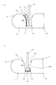
図1~図4は本発明の実施の形態1に係る印刷方法を説明するものであって、図1はフローチャート、図2~図4は印刷工程毎に示す断面図である。なお、図2~図4は、模式的に一部を誇張して示すものであって、本発明は、印刷体の形状や絵柄(インキ)の形態(形状、分布等)を図示するものに限定するものではない。また、以下の説明において、共通する内容については、符号に付した添え字「a、b、c・・・」の記載を省略する場合がある。
そして、小絵柄2のそれぞれを平面に展開した小展開絵柄3a、3b1、3b2・・・3f(以下、それぞれを「小展開絵柄3」と称す)を作成する(図1に示すS3)。
このとき、小印刷原版30bには、小展開絵柄3b1および小展開絵柄3b2に沿ってインキが載せられる。なお、インキを載せる方法は限定されるものではなく、小展開絵柄3が形成された凸版の凸部あるは凹版の凹部にインキを載せても、あるいは、平板に印刷(インクジェットプリンター、スクリーン印刷、グラビア印刷、オフセット印刷等)によってインキを載せてもよい。
このとき、小印刷原版30の法線と平行に押し付けられる。なお、小印刷用ブランケット40を多軸ロボットを使用して、それそれが対応する小印刷原版30に押し付けてもよい。
このとき、小印刷用ブランケット40aは図示しない多軸ロボットのアーム50に把持され、正確に位置決めされ、且つ、小被印刷面1aの略中央における法線と平行(矢印にて示す)に押し付けられている。
このとき、小印刷用ブランケット40bは図示しない多軸ロボットのアーム50に把持され、正確に位置決めされ、且つ、小被印刷面1b1の略中央における法線と小被印刷面1b2の略中央における法線との一方の法線に平行、または両方の法線の中間に位置する線に平行(矢印にて示す)に、押し付けられている。
このとき、小印刷用ブランケット40cは図示しない多軸ロボットのアーム50に把持され、被印刷体100の凹部101に侵入して正確に位置決めされ、且つ、小被印刷面1cの略中央における法線(矢印にて示す)に平行に、押し付けられている。
なお、図4の(a)においては、小印刷用ブランケット40cを把持するアーム50の先端部は、凹部101に侵入しているが、本発明はこれに限定するものではなく、小印刷用ブランケット40cの一部(図中、上部)を把持して、アーム50の先端部は凹部101に侵入しないようにしてもよい。
このとき、小印刷用ブランケット40dは図示しない多軸ロボットのアーム50に把持され、被印刷体100の凹部101に侵入して正確に位置決めされ、且つ、小被印刷面1dの略中央における法線(矢印にて示す)に平行に、押し付けられている。
したがって、かかる一連の小絵柄2の印刷によって、被印刷体100の被印刷面10に絵柄20が印刷される。このとき、小絵柄2は多軸ロボットのアーム50によって、正確に位置決めされながら、凹部101も印刷されている。
なお、以上は、小印刷用ブランケット40を個別に把持して、それぞれ別個に小絵柄2を印刷しているが、複数のアームを用いて、複数の小絵柄2を略同時に印刷するようにしてもよい。また、小絵柄2を印刷する順番は限定されるものではない。
さらに、本発明は、多軸ロボットを使用するものに限定するものではない。たとえば、多軸ロボットに替えて、位置決め機能と押し付け機能を具備する手段を使用してもよいし、小印刷用ブランケット40等に位置決め機構を設けて手動によって押し付けるようにしてもよい。
図5は本発明の実施の形態2に係る被印刷体を模式的に示す断面図である。なお、実施の形態1と同じ部分にはこれと同じ符号を付し、一部の説明を省略する。
図5において、被印刷体200は、被印刷体100に、実施の形態1に説明した印刷方法によって絵柄20が印刷されたものに同じである。すなわち、凹部101にも絵柄20の一部である小絵柄2c、2d、2eが印刷されている。
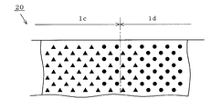
図6~図8は本発明の実施の形態3に係る印刷方法を説明するものであって、図6は絵柄を分割する要領を模式的に示す平面図、図7の小展開絵柄における網点の配置の一例を拡大して模式的に示す平面図、図8は印刷の重なり範囲を拡大して模式的に示す平面図である。なお、図6~図8は、模式的に示すものであって、本発明は、被印刷体の形状や網点の形態(形状、分布等)を図示するものに限定するものではない。また、実施の形態1と同じ部分または相等する部分には同じ符号を付し、一部の説明を省略する。
そして、小絵柄・・・2c、2d、2e・・・のそれぞれを平面に展開した小展開絵柄・・・3c、3d、3e・・・を作成する(図1に示すS3に準じる)。
そして、小被印刷面・・・1c、1d、1e・・・のそれぞれに対応した小印刷原版・・・30c、30d、30e・・・に、それぞれが対応する小展開絵柄・・・3c、3d、3e・・・に沿ってインキを載せる(図1に示すS4に準じる)。
小展開絵柄3cの小展開絵柄3dに接する所定幅に相等する境界範囲3cdと、小展開絵柄3dの小展開絵柄3cに接する所定幅に相等する境界範囲3dcとを併せた重なり範囲5cdに載せられるインキの量は、拡大小展開絵柄3bcdに相等する範囲から重なり範囲5cdを除いた内側範囲3ccに載せられるインキの量より少なくなっている(図7の(a)参照)。
そして、重なり範囲5cdに載せられるインキの量と、小展開絵柄3dの小展開絵柄3eに接する所定幅に相等する境界範囲3deと、小展開絵柄3eの小展開絵柄3dに接する所定幅に相等する境界範囲3edとを併せた重なり範囲5deに載せられるインキの量は、拡大小展開絵柄3cdeに相等する範囲から重なり範囲5cdおよび重なり範囲5deを除いた内側範囲3ddに載せられるインキの量より少なくなっている(図7の(b)参照)。
あるいは、重なり範囲5cdにおける網点の大きさが内側範囲3ccや内側範囲3ddにおける網点の大きさより少なくなっている。あるいは、重なり範囲5cdにおける網点の大きさが、内側範囲3ccや内側範囲3ddから離れる程除々に縮小している。なお、インキを載せる方法は限定されるものではないことは実施の形態1に同じである。
次に、小印刷用ブランケット・・・40c、40d、40e・・・を、これが対応する小被印刷面・・・1c、1d・、1e・・に押し付けて、そこに小絵柄・・・2c、2d、2e・・・を印刷している(図1に示すS6に準じる)。
このとき、たとえば、小印刷原版30cにおいて、小展開絵柄3dとの重なり範囲5cdに相等する範囲に載せられるインキの量を「α」%に減らし、一方、小印刷原版30dにおいて、小展開絵柄3cとの重なり範囲5cdに相等する範囲に載せられるインキの量を「100-α」%に減らしておけば、両者の重なり範囲5cdにおける絵柄は濃くなることも、薄くなることもなく、美観を損ねることがない。
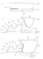
図9~図16は本発明の実施の形態4に係る印刷方法を説明するものであって、図9はフローチャート、図10~図13は印刷工程毎に示す断面図、図14~図16は印刷方法のバリエーションを示す断面図である。なお、図10~図16は、模式的に一部を誇張して示すものであって、本発明は、印刷体の形状や絵柄(インキ)の形態(形状、分布等)を図示するものに限定するものではない。また、以下の説明において、共通する内容については、符号に付した添え字「a、b、c・・・」の記載を省略する場合がある。
被印刷面に印刷しようとする絵柄を小被印刷面のそれぞれに印刷される小絵柄に分割する工程(S2)と、
小絵柄のそれぞれを平面に展開した小展開絵柄を作成する工程(S3)と、
小被印刷面のそれぞれに対応した小印刷原版に、それぞれが対応する小被印刷面における小展開絵柄に沿ってインキを載せる工程(S4)と、
小被印刷面のそれぞれに対応した小印刷用ブランケットを、それそれが対応する小印刷原版に押し付けて、それぞれの小印刷用ブランケットに前記インキを転写する工程(S5)と、
小印刷用ブランケットを、これが対応する小被印刷面に、昇降手段を用いて押し付けて、そこに小絵柄を印刷する工程(S6の2)とを、有している。
図10において、被印刷体400の被印刷面410(位置411~位置416)を複数の小被印刷面401a、401b1、401b2、401c、401d(以下、それぞれを「小被印刷面401」と称す場合がある)に分割して(図9に示すS1)、被印刷面410に印刷しようとする絵柄420(図示しない)を小被印刷面401のそれぞれに印刷される小絵柄402a、402b1、402b2、402c、402d(以下、それぞれを「小絵柄402」と称す場合がある)に分割する(図9に示すS2)。そして、小絵柄402のそれぞれを平面に展開した小展開絵柄403a、403b1、403b2、403c、403d(以下、それぞれを「小展開絵柄403」と称す場合がある)を作成する(図9に示すS3)。
そして、小被印刷面401のそれぞれに対応した小印刷用ブランケット440a、440b、440c、440d(以下、それぞれを「小印刷用ブランケット440」と称す場合がある)を、それそれが対応する小印刷原版430に押し付けて、それぞれの小印刷用ブランケット440にインキ404を転写する(図9に示すS5)。
さらに、小印刷用ブランケット440、これが対応する小被印刷面401に押し付けて、そこに小絵柄402を印刷する(図9に示すS6の2)。以下、小被印刷面401のそれぞれについて詳細に説明する。
図11の(b)において、被印刷体400は基板490の載置面491に載置されている。そして、小印刷用ブランケット440cを、これが対応する小被印刷面401cの直上に配置して、載置面491の法線方向(図11において上下方向)に沿って、押し下げている。
なお、本発明は、前記押し下げる(押し付ける)装置を限定するものではなく、小被印刷面401cと水平方向に位置合わせをすることができ、小印刷用ブランケット440cを把持して上下方向に昇降自在なものであればよい。
図12の(c)において、小印刷用ブランケット440bを下方に押し付けている。このため、小印刷用ブランケット440bは、小被印刷面401b1および小被印刷面401b2になじむよう変形し、該表面にインキ404b1およびインキ404b2が転写され、小絵柄402b1および小絵柄402b2が印刷される(図9に示すS6の2)。
なお、図11と同様に、前記押し下げる(押し付ける)装置を限定するものではない。
図13の(b)において、被印刷体400は基板490の載置面491に載置されている。なお、載置面491はその周囲の当接面492よりも一段高くなっている。そして、小印刷用ブランケット440aの頂点441aを、これが対応する小被印刷面401aから水平方向で離れた位置に配置して、載置面491の法線方向(図13において上下方向)に沿って、押し下げている。
このとき、当接面492は載置面491に対して一段低くなっているため、小印刷用ブランケット440cのインキ404aが転写された面は、小被印刷面401aの法線方向により平行に膨張して小被印刷面401aに押し付けられる。したがって、小絵柄402aの印刷精度が向上している。また、以上は、当接面492と載置面491とが平行で段差を有するものであるが、当接面492を載置面491(段差部)に近づける程、低くなるように傾斜させてもよい。
図14は、図12に示す小絵柄402b1および小絵柄402b2の印刷方法のバリエーションを示している。
図14の(a)において、小被印刷面401b1および小被印刷面401b2に対応した小印刷原版430bに、小展開絵柄403b1および小展開絵柄403b2に沿ってインキ404b1およびインキ404b2を載せ(図9に示すS4)、小印刷用ブランケット451bを小展開絵柄403b1に、小印刷用ブランケット452bを小展開絵柄403b2に、それぞれ押し付けている(図9に示すS5)。
すなわち、小印刷用ブランケット440b、442bは平面状に変形した状態で、その表面にそれぞれインキ404b1、404b2が転写されている。このとき、前記押し付けない状態では、小印刷用ブランケット440bは、断面略円弧状(円柱を半分にした形態)であって、その最下点が小展開絵柄403b1の中心に一致し、小印刷用ブランケット452bは、断面略円弧状(円柱を半分にした形態)であって、その最下点が小展開絵柄403b2の中心に一致している。
図14の(c)において、小印刷用ブランケット451b、442bを下方に押し付けている。このため、小印刷用ブランケット451bおよび小印刷用ブランケット452bは、それぞれ小被印刷面401b1および小被印刷面401b2になじむよう変形し、該表面にインキ404b1およびインキ404b2が転写され、小絵柄402b1および小絵柄402b2が印刷される(図9に示すS6の2)。
図15は、小被印刷面401dに小絵柄402dを印刷するバリエーションを示している。
図15の(a)において、小被印刷面401dに対応した小印刷原版430ad、小展開絵柄403dに沿ってインキ404dを載せ(図9に示すS4)、小印刷用ブランケット440dを小印刷原版430dに押し付けている(図9に示すS5)。すなわち、小印刷用ブランケット440cは平面状に変形した状態で、その表面にインキ404cが転写されている。
図15の(b)において、被印刷体400は基板490の載置面491に載置されている。なお、載置面491はその周囲の当接面492よりも一段高くなっている。そして、小印刷用ブランケット440dの頂点441dを、これが対応する小被印刷面401dから水平方向で離れた位置に配置して、載置面491の法線方向(上下方向)に沿って、押し下げている。
なお、かかる水平方向に移動させる手段は限定するものではなく、被印刷体400を水平方向(X方向およびY方向)に移動させても、小印刷用ブランケット440d(昇降装置に同じ)を水平方向(X方向およびY方向)に移動させても、あるいは両者を水平方向(X方向およびY方向)に移動させてもよい。
図16は、小被印刷面401dに小絵柄402dを印刷するバリエーションを示している。
図16の(a)は、バリエーション2に示す図15の(a)に同じである。
図16の(b)において、被印刷体400は基板490の載置面491に載置されている。このとき、載置面491の周囲に一段低くなった当接面492と、被印刷体400の小被印刷面401dに対向した傾斜壁493が設けられている。傾斜壁493は小被印刷面401dから所定の距離だけ離れているから、小印刷用ブランケット440dは傾斜壁493および小被印刷面401dに触れることなく下降し、やがて、小印刷用ブランケット440dの頂点441dが、これが対応する小被印刷面401dから水平方向で離れた位置で、当接面492に当接する。
なお、傾斜壁493の形状は限定するものではなく、また、昇降に加えて、被印刷体400と小印刷用ブランケット440d(昇降装置に同じ)とを相対的に水平方向(X方向およびY方向)に移動させてもよい。
また、このような傾斜壁493に準じた傾斜壁を、小被印刷面401aへの小絵柄402aの印刷(小印刷用ブランケット440aの昇降)の際に使用してもよい。
図17は本発明の実施の形態5に係る被印刷体を模式的に示す断面図である。なお、実施の形態4と同じ部分にはこれと同じ符号を付し、一部の説明を省略する。すなわち、被印刷体500は実施の形態4に説明したように、上下方向に昇降する昇降手段によって絵柄420が印刷されるから、簡便な装置によって安価に提供される。
図18~図20は本発明の実施の形態6に係る印刷方法を説明するものであって、図18は絵柄を分割する要領を模式的に示す平面図、図18は小展開絵柄における網点の配置の一例を拡大して模式的に示す平面図、図20は印刷の重なり範囲を拡大して模式的に示す平面図である。なお、図19~図20は、模式的に示すものであって、本発明は、被印刷体の形状や網点の形態(形状、分布等)を図示するものに限定するものではない。また、実施の形態4と同じ部分または相等する部分には同じ符号を付し、一部の説明を省略する。
そして、小絵柄・・・402f、402g、402h・・・のそれぞれを平面に展開した小展開絵柄・・・403f、403g、403h・・・を作成する(図9に示すS3に準じる)。
そして、小被印刷面・・・401f、401g、401h・・・のそれぞれに対応した小印刷原版・・・430f、430g、430h・・・に、それぞれが対応する小展開絵柄・・・403f、403g、403h・・・に沿ってインキを載せる(図9に示すS4に準じる)。
小展開絵柄403fの小展開絵柄403gに接する所定幅に相等する境界範囲403fgと、小展開絵柄403gの小展開絵柄403fに接する所定幅に相等する境界範囲403gfとを併せた重なり範囲405fgに載せられるインキの量は、拡大小展開絵柄403efgに相等する範囲から重なり範囲405fgを除いた内側範囲403ffに載せられるインキの量より少なくなっている(図18の(a)参照)。
そして、重なり範囲405fgに載せられるインキの量と、小展開絵柄403gの小展開絵柄403hに接する所定幅に相等する境界範囲403ghと、小展開絵柄403hの小展開絵柄403gに接する所定幅に相等する境界範囲403hgとを併せた重なり範囲405ghに載せられるインキの量は、拡大小展開絵柄403fghに相等する範囲から重なり範囲405fgおよび重なり範囲405ghを除いた内側範囲403ggに載せられるインキの量より少なくなっている。
あるいは、重なり範囲405fgにおける網点の大きさが内側範囲403ffや内側範囲403ggにおける網点の大きさより少なくなっている。あるいは、重なり範囲405fgにおける網点の大きさが、内側範囲403ffや内側範囲403ggから離れる程除々に縮小している。なお、インキを載せる方法は限定されるものではないことは実施の形態4に同じである。
次に、小印刷用ブランケット・・・440f、440g、440h・・・を、これが対応する小被印刷面・・・401f、401g・、401h・・に押し付けて、そこに小絵柄・・・402f、402g、402h・・・を印刷している(図9に示すS6の2に準じる)。
このとき、たとえば、小印刷原版430fにおいて、小展開絵柄403gとの重なり範囲405fgに相等する範囲に載せられるインキの量を「α」%に減らし、一方、小印刷原版430gにおいて、小展開絵柄403fとの重なり範囲405fgに相等する範囲に載せられるインキの量を「100-α」%に減らしておけば、両者の重なり範囲405fgにおける絵柄は濃くなることも、薄くなることもなく、美観を損ねることがない。
2 小絵柄
3 小展開絵柄
4 小印刷用ブランケット絵柄
5 重なり範囲
10 被印刷面
20 絵柄
30 小印刷原版
40 小印刷用ブランケット
50 アーム
100 被印刷体(印刷前)
101 凹部
200 被印刷体(印刷済み)
400 被印刷体(実施の形態4)
401 小被印刷面
402 小絵柄
403 小展開絵柄
404 インキ
405fg 重なり範囲
410 被印刷面
420 絵柄
430 小印刷原版
440 小印刷用ブランケット
441 頂点
451b 小印刷用ブランケット
452b 小印刷用ブランケット
490 基板
491 載置面
492 当接面
493 傾斜壁
493 傾斜面
490 基板
500 被印刷体(実施の形態5)
Claims (12)
- 被印刷体の被印刷面を複数の小被印刷面に分割して、前記被印刷面に印刷される絵柄を前記小被印刷面のそれぞれに印刷される小絵柄に分割する工程と、
該小絵柄を平面に展開した小展開絵柄を作成する工程と、
前記複数の小被印刷面のそれぞれに対応した小印刷原版に、それぞれが対応する小被印刷面における前記小展開絵柄に沿ってインキを載せる工程と、
前記複数の小被印刷面のそれぞれに対応した小印刷用ブランケットを、それそれが対応する小印刷原版に押し付けて、それぞれの小印刷用ブランケットに前記インキを転写する工程と、
前記複数の小印刷用ブランケットを、それぞれが対応する小被印刷面に押し付けて、該小被印刷面に前記小絵柄を印刷することによって、前記被印刷面に前記絵柄を印刷する工程と、
を有することを特徴とする印刷方法。 - 被印刷体の被印刷面を、それぞれの境界が所定の幅で重なるように複数の小被印刷面に分割して、前記被印刷面に印刷される絵柄を前記小被印刷面のそれぞれに印刷される小絵柄に分割する工程と、
該小絵柄を平面に展開した小展開絵柄を作成する工程と、
前記複数の小被印刷面のそれぞれに対応した小印刷原版に、それぞれが対応する小被印刷面における前記小展開絵柄に沿って、前記境界の所定の幅におけるインキの量が、前記境界の所定の幅を除く範囲におけるインキの量より少なくなるように、インキを載せる工程と、
前記複数の小被印刷面のそれぞれに対応した小印刷用ブランケットを、それそれが対応する小印刷原版に押し付けて、それぞれの小印刷用ブランケットに前記インキを転写する工程と、
前記複数の小印刷用ブランケットを、それぞれが対応する小被印刷面に押し付けて、該小被印刷面に前記小絵柄を印刷することによって、前記被印刷面に前記絵柄を印刷する工程と、
を有することを特徴とする印刷方法。 - 被印刷体の被印刷面を複数の小被印刷面に分割して、前記被印刷面に印刷される絵柄を前記小被印刷面のそれぞれに印刷される小絵柄に分割する工程と、
該小絵柄を平面に展開した小展開絵柄を作成する工程と、
前記複数の小被印刷面のそれぞれに対応した小印刷原版に、それぞれが対応する小被印刷面における前記小展開絵柄に沿ってインキを載せる工程と、
前記複数の小被印刷面のそれぞれに対応した小印刷用ブランケットを、それそれが対応する小印刷原版に押し付けて、それぞれの小印刷用ブランケットに前記インキを転写する工程と、
前記複数の小印刷用ブランケットを、それぞれが対応する小被印刷面に押し付けて、該小被印刷面に前記小絵柄を印刷することによって、前記被印刷面に前記絵柄を印刷する工程と、
を有し、
前記複数の小印刷用ブランケットを、それそれが対応する小印刷原版の法線と平行に該小印刷原版に押し付け、且つ、それぞれが対応する小被印刷面の平均的な法線と平行に該小被印刷面に押し付けることを特徴とする印刷方法。 - 被印刷体の被印刷面を、それぞれの境界が所定の幅で重なるように複数の小被印刷面に分割して、前記被印刷面に印刷される絵柄を前記小被印刷面のそれぞれに印刷される小絵柄に分割する工程と、
該小絵柄を平面に展開した小展開絵柄を作成する工程と、
前記複数の小被印刷面のそれぞれに対応した小印刷原版に、それぞれが対応する小被印刷面における前記小展開絵柄に沿って、前記境界の所定の幅におけるインキの量が、前記境界の所定の幅を除く範囲におけるインキの量より少なくなるように、インキを載せる工程と、
前記複数の小被印刷面のそれぞれに対応した小印刷用ブランケットを、それそれが対応する小印刷原版に押し付けて、それぞれの小印刷用ブランケットに前記インキを転写する工程と、
前記複数の小印刷用ブランケットを、それぞれが対応する小被印刷面に押し付けて、該小被印刷面に前記小絵柄を印刷することによって、前記被印刷面に前記絵柄を印刷する工程と、
を有し、
前記複数の小印刷用ブランケットを、それそれが対応する小印刷原版の法線と平行に該小印刷原版に押し付け、且つ、それぞれが対応する小被印刷面の平均的な法線と平行に該小被印刷面に押し付けることを特徴とする印刷方法。 - 前記複数の小被印刷面のそれぞれの位置を記憶し、且つ、前記複数の小被印刷面のそれぞれに対応した前記小印刷用ブランケットを順次把持すると共に、該把持した小印刷用ブランケットを、これが対応した前記小被印刷面に押し付ける多軸ロボットを用いて、前記絵柄を印刷する工程を実行することを特徴とする請求項1乃至4の何れかに記載の印刷方法。
- 前記複数の小被印刷面のそれぞれの位置を記憶し、且つ、前記複数の小被印刷面のそれぞれに対応した前記小印刷用ブランケットを順次把持すると共に、該把持した小印刷用ブランケットを、これが対応した前記小被印刷面に押し付ける多軸ロボットを用いて、前記絵柄を印刷する工程を実行し、
前記小被印刷面が、前記被印刷体の内部に陥入した凹部の側面または底面であって、
該側面または底面に対応した前記小印刷用ブランケットが、前記凹部に侵入自在であることを特徴とする請求項1乃至4の何れかに記載の印刷方法。 - 前記複数の小被印刷面のそれぞれの位置を記憶し、且つ、前記複数の小被印刷面のそれぞれに対応した前記小印刷用ブランケットを順次把持すると共に、該把持した小印刷用ブランケットを、これが対応した前記小被印刷面に押し付ける多軸ロボットを用いて、前記絵柄を印刷する工程を実行し、
前記小被印刷面が、前記被印刷体の内部に陥入した凹部の側面または底面であって、
該側面または底面に対応した前記小印刷用ブランケットを把持する前記多軸ロボットの把持部が、前記凹部に侵入自在であることを特徴とする請求項1乃至4の何れかに記載の印刷方法。 - 被印刷体の被印刷面を複数の小被印刷面に分割して、前記被印刷面に印刷される絵柄を前記小被印刷面のそれぞれに印刷される小絵柄に分割する工程と、
該小絵柄を平面に展開した小展開絵柄を作成する工程と、
前記複数の小被印刷面のそれぞれに対応した小印刷原版に、それぞれが対応する小被印刷面における前記小展開絵柄に沿ってインキを載せる工程と、
前記複数の小被印刷面のそれぞれに対応した小印刷用ブランケットを、それそれが対応する小印刷原版に押し付けて、それぞれの小印刷用ブランケットに前記インキを転写する工程と、
前記複数の小印刷用ブランケットを、それぞれが対応する小被印刷面に押し付けて、該小被印刷面に前記小絵柄を印刷することによって、前記被印刷面に前記絵柄を印刷する工程と、
を有し、
前記絵柄を印刷する工程が、前記被印刷体が載置される基板に対して昇降する昇降装置を用いるものであって、
該昇降装置が、前記複数の小被印刷面に対応した前記小印刷用ブランケットを把持し、該小印刷用ブランケットを、これが対応した前記小被印刷面に押し付けることを特徴とする印刷方法。 - 被印刷体の被印刷面を、それぞれの境界が所定の幅で重なるように複数の小被印刷面に分割して、前記被印刷面に印刷される絵柄を前記小被印刷面のそれぞれに印刷される小絵柄に分割する工程と、
該小絵柄を平面に展開した小展開絵柄を作成する工程と、
前記複数の小被印刷面のそれぞれに対応した小印刷原版に、それぞれが対応する小被印刷面における前記小展開絵柄に沿って、前記境界の所定の幅におけるインキの量が、前記境界の所定の幅を除く範囲におけるインキの量より少なくなるように、インキを載せる工程と、
前記複数の小被印刷面のそれぞれに対応した小印刷用ブランケットを、それそれが対応する小印刷原版に押し付けて、それぞれの小印刷用ブランケットに前記インキを転写する工程と、
前記複数の小印刷用ブランケットを、それぞれが対応する小被印刷面に押し付けて、該小被印刷面に前記小絵柄を印刷することによって、前記被印刷面に前記絵柄を印刷する工程と、
を有し、
前記絵柄を印刷する工程が、前記被印刷体が載置される基板に対して昇降する昇降装置を用いるものであって、
該昇降装置が、前記複数の小被印刷面に対応した前記小印刷用ブランケットを把持し、該小印刷用ブランケットを、これが対応した前記小被印刷面に押し付けることを特徴とする印刷方法。 - 前記絵柄を印刷する工程が、前記被印刷体が載置される基板に対して昇降する昇降装置を用いるものであって、
前記被印刷体の側面に位置する小被印刷面に前記絵柄の一部を印刷する際、前記昇降装置は、前記小被印刷面に対応した前記小印刷用ブランケットを把持し、該小印刷用ブランケットの前記インキが転写されていない部分を前記基板に押し付けることによって、前記小印刷用ブランケットの前記インキが転写された部分を、これが対応した前記小被印刷面に押し付けることを特徴とする請求項8または9に記載の印刷方法。 - 前記絵柄を印刷する工程が、前記被印刷体が載置される基板に対して昇降する昇降装置を用いるものであって、
前記被印刷体の側面に位置する小被印刷面に前記絵柄の一部を印刷する際、前記昇降装置は、前記小被印刷面に対応した前記小印刷用ブランケットを把持し、該小印刷用ブランケットの前記インキが転写されていない部分を前記基板に押し付けることによって、前記小印刷用ブランケットの前記インキが転写された部分を、これが対応した前記小被印刷面に押し付け、
前記小印刷用ブランケットの前記インキが転写されていない部分が押し付けられる前記基板の範囲は、前記被印刷体が載置されている前記基板の範囲に対し、前記昇降装置の昇降方向で下降側に位置していることを特徴とする請求項8または9に記載の印刷方法。 - 請求項1、2、3、4、8または9の何れかに記載の印刷方法によって印刷された被印刷面を有することを特徴とする被印刷体。
Priority Applications (4)
| Application Number | Priority Date | Filing Date | Title |
|---|---|---|---|
| EP10758159.7A EP2415613B1 (en) | 2009-04-01 | 2010-01-26 | Printing method and object to be printed |
| CN201080014563.6A CN102378692B (zh) | 2009-04-01 | 2010-01-26 | 印刷方法及被印刷体 |
| KR1020117021667A KR101258354B1 (ko) | 2009-04-01 | 2010-01-26 | 인쇄 방법 및 피인쇄체 |
| US13/256,662 US8893617B2 (en) | 2009-04-01 | 2010-01-26 | Printing method and to-be-printed object |
Applications Claiming Priority (4)
| Application Number | Priority Date | Filing Date | Title |
|---|---|---|---|
| JP2009089225A JP5164909B2 (ja) | 2009-04-01 | 2009-04-01 | 印刷方法および被印刷体 |
| JP2009-089225 | 2009-04-01 | ||
| JP2009143480A JP5295005B2 (ja) | 2009-06-16 | 2009-06-16 | 印刷方法および被印刷体 |
| JP2009-143480 | 2009-06-16 |
Publications (1)
| Publication Number | Publication Date |
|---|---|
| WO2010113373A1 true WO2010113373A1 (ja) | 2010-10-07 |
Family
ID=42827691
Family Applications (1)
| Application Number | Title | Priority Date | Filing Date |
|---|---|---|---|
| PCT/JP2010/000409 Ceased WO2010113373A1 (ja) | 2009-04-01 | 2010-01-26 | 印刷方法および被印刷体 |
Country Status (5)
| Country | Link |
|---|---|
| US (1) | US8893617B2 (ja) |
| EP (1) | EP2415613B1 (ja) |
| KR (1) | KR101258354B1 (ja) |
| CN (1) | CN102378692B (ja) |
| WO (1) | WO2010113373A1 (ja) |
Cited By (1)
| Publication number | Priority date | Publication date | Assignee | Title |
|---|---|---|---|---|
| CN113601967A (zh) * | 2021-08-05 | 2021-11-05 | 业成科技(成都)有限公司 | 油墨印刷治具及装置 |
Families Citing this family (10)
| Publication number | Priority date | Publication date | Assignee | Title |
|---|---|---|---|---|
| FR2990382B1 (fr) * | 2012-05-10 | 2017-07-28 | Sgd Sa | Procede et machine de decor de flacons par tampographie indirecte en coquille |
| MX369706B (es) * | 2013-03-11 | 2019-11-19 | Illinois Tool Works | Inserto de copa desechable para tampografía y decoración. |
| ITRM20130624A1 (it) * | 2013-11-13 | 2015-05-14 | Elia Annalisa D | Metodo di stampa serigrafica perfezionato. |
| JP6278942B2 (ja) * | 2015-10-21 | 2018-02-14 | 日本航空電子工業株式会社 | フレキソ印刷による絶縁膜の形成方法 |
| US11072163B2 (en) | 2016-04-28 | 2021-07-27 | Shuhou Co., Ltd | Printing blanket, method for manufacturing the same, and printing method using the same |
| CN107921809B (zh) | 2016-08-01 | 2020-03-10 | 株式会社秀峰 | 印刷用橡皮布及印刷方法 |
| KR102100669B1 (ko) * | 2016-09-27 | 2020-05-27 | (주)엘지하우시스 | 차량용 내장재의 제조방법 및 차량용 내장재 |
| JP6955716B2 (ja) * | 2017-08-10 | 2021-10-27 | マイクロ・テック株式会社 | スクリーン印刷装置及びスクリーン印刷方法 |
| CN109968852B (zh) * | 2019-02-28 | 2020-04-14 | 浙江大学 | 一种通用的二维平面到三维复杂表面的直接转印方法 |
| KR102917642B1 (ko) * | 2019-11-12 | 2026-01-26 | 삼성디스플레이 주식회사 | 인쇄층 형성 장치, 커버 글라스 및 이의 제조 방법 |
Citations (5)
| Publication number | Priority date | Publication date | Assignee | Title |
|---|---|---|---|---|
| JPS6090761A (ja) * | 1983-10-25 | 1985-05-21 | Toppan Printing Co Ltd | 段差面を有する被印刷体への印刷方法 |
| JPH02239972A (ja) | 1989-03-14 | 1990-09-21 | Shiyuuhou:Kk | 曲面への印刷方法 |
| JPH02301479A (ja) * | 1989-05-17 | 1990-12-13 | Murata Mfg Co Ltd | パッド印刷方法 |
| JPH11268395A (ja) * | 1998-03-23 | 1999-10-05 | Yazaki Corp | 円筒形状文字板の印刷方法及び印刷用治具 |
| JP2005125682A (ja) * | 2003-10-27 | 2005-05-19 | Noboru Murai | 立体物の多色刷り印刷方法とそのためのパッド式印刷機 |
Family Cites Families (9)
| Publication number | Priority date | Publication date | Assignee | Title |
|---|---|---|---|---|
| EP0092988B1 (en) * | 1982-04-24 | 1990-06-20 | British Ceramic Research Limited | Off-set printing |
| DE3436688C1 (de) | 1984-10-05 | 1986-07-03 | TAMPOflex GmbH, 7257 Ditzingen | Verfahren fuer den Mehrfarben-Tampondruck |
| DE69415473T2 (de) * | 1993-10-29 | 1999-06-17 | Sony Corp., Tokio/Tokyo | Vorrichtung und Verfahren zum Bedrucken einer Kassette |
| SE9703410D0 (sv) * | 1997-09-22 | 1997-09-22 | Ericsson Telefon Ab L M | Sätt att överföra en bild på oregelbundna ytor |
| KR100945356B1 (ko) * | 2002-12-27 | 2010-03-09 | 엘지디스플레이 주식회사 | 액정표시소자의 칼라필터 제조방법 |
| CN100564056C (zh) | 2004-09-10 | 2009-12-02 | 株式会社秀峰 | 向曲面印刷的方法以及以该方法获得的印刷曲面体 |
| US7468814B2 (en) * | 2005-02-08 | 2008-12-23 | Astro-Med, Inc. | Algorithm for controlling half toning process |
| CN101007475A (zh) * | 2006-01-27 | 2007-08-01 | 上海伊诺特玩具有限公司 | 球形/异形产品全印印刷工艺和设备 |
| JP5062551B2 (ja) * | 2007-01-30 | 2012-10-31 | 株式会社吉野工業所 | タンポ印刷方法とタンポ印刷用のタンポ転写体 |
-
2010
- 2010-01-26 WO PCT/JP2010/000409 patent/WO2010113373A1/ja not_active Ceased
- 2010-01-26 US US13/256,662 patent/US8893617B2/en active Active
- 2010-01-26 EP EP10758159.7A patent/EP2415613B1/en active Active
- 2010-01-26 KR KR1020117021667A patent/KR101258354B1/ko active Active
- 2010-01-26 CN CN201080014563.6A patent/CN102378692B/zh active Active
Patent Citations (5)
| Publication number | Priority date | Publication date | Assignee | Title |
|---|---|---|---|---|
| JPS6090761A (ja) * | 1983-10-25 | 1985-05-21 | Toppan Printing Co Ltd | 段差面を有する被印刷体への印刷方法 |
| JPH02239972A (ja) | 1989-03-14 | 1990-09-21 | Shiyuuhou:Kk | 曲面への印刷方法 |
| JPH02301479A (ja) * | 1989-05-17 | 1990-12-13 | Murata Mfg Co Ltd | パッド印刷方法 |
| JPH11268395A (ja) * | 1998-03-23 | 1999-10-05 | Yazaki Corp | 円筒形状文字板の印刷方法及び印刷用治具 |
| JP2005125682A (ja) * | 2003-10-27 | 2005-05-19 | Noboru Murai | 立体物の多色刷り印刷方法とそのためのパッド式印刷機 |
Non-Patent Citations (1)
| Title |
|---|
| See also references of EP2415613A4 * |
Cited By (1)
| Publication number | Priority date | Publication date | Assignee | Title |
|---|---|---|---|---|
| CN113601967A (zh) * | 2021-08-05 | 2021-11-05 | 业成科技(成都)有限公司 | 油墨印刷治具及装置 |
Also Published As
| Publication number | Publication date |
|---|---|
| KR20110126150A (ko) | 2011-11-22 |
| KR101258354B1 (ko) | 2013-04-30 |
| US20110315035A1 (en) | 2011-12-29 |
| EP2415613A4 (en) | 2013-04-24 |
| CN102378692B (zh) | 2015-01-14 |
| EP2415613B1 (en) | 2016-03-30 |
| EP2415613A1 (en) | 2012-02-08 |
| CN102378692A (zh) | 2012-03-14 |
| US8893617B2 (en) | 2014-11-25 |
Similar Documents
| Publication | Publication Date | Title |
|---|---|---|
| WO2010113373A1 (ja) | 印刷方法および被印刷体 | |
| CN110509680B (zh) | 一种印刷套准方法及系统 | |
| US20190224959A1 (en) | Apparatus and method for forming high definition lithographic images on containers | |
| TW202120340A (zh) | 用於決定印刷機之印刷參數的方法及測試平台 | |
| JP2011000736A (ja) | 印刷方法および被印刷体 | |
| EP1367618A3 (en) | Indicator portion forming method for push switch and push switch having an indicator portion | |
| US20100242760A1 (en) | Apparatus and method for mounting printing plate | |
| KR20080047980A (ko) | 인쇄기 및 인쇄 방법 | |
| US20140076184A1 (en) | Method for forming structured microdots | |
| JP5164909B2 (ja) | 印刷方法および被印刷体 | |
| US20020100378A1 (en) | Objects having thereon printed full-color process image of high definition and methods for printing on the same | |
| JP2009190264A (ja) | 印刷版及び缶の印刷装置 | |
| US20040221757A1 (en) | Lithographic plate imaging system to minimize plate misregistration for multicolor printing applications | |
| JPWO2018025299A1 (ja) | 印刷用ブランケット及び印刷方法 | |
| WO2014157291A1 (ja) | 製版方法、製版装置、印刷装置及び印刷版 | |
| JP2009160905A (ja) | 凸版印刷版 | |
| JP4423916B2 (ja) | 可撓性金属平板状の凹版を用いたパターン印刷装置 | |
| US8599232B2 (en) | Integral cushion for flexographic printing plates | |
| JP2004009425A (ja) | 記録方法及び記録装置 | |
| JPH08118779A (ja) | パッド印刷方法 | |
| US20140076180A1 (en) | System for forming security markings using structured microdots | |
| CN214873377U (zh) | 压力控制结构及激光直接雕刻橡胶版 | |
| JP2010131879A (ja) | 印刷版および印刷方法 | |
| JP3180521B2 (ja) | 印刷凸版を用いた電子部品への表示付与方法 | |
| WO2013043476A1 (en) | Integral cushion for flexographic printing plates |
Legal Events
| Date | Code | Title | Description |
|---|---|---|---|
| WWE | Wipo information: entry into national phase |
Ref document number: 201080014563.6 Country of ref document: CN |
|
| 121 | Ep: the epo has been informed by wipo that ep was designated in this application |
Ref document number: 10758159 Country of ref document: EP Kind code of ref document: A1 |
|
| WWE | Wipo information: entry into national phase |
Ref document number: 2010758159 Country of ref document: EP |
|
| WWE | Wipo information: entry into national phase |
Ref document number: 13256662 Country of ref document: US |
|
| ENP | Entry into the national phase |
Ref document number: 20117021667 Country of ref document: KR Kind code of ref document: A |
|
| NENP | Non-entry into the national phase |
Ref country code: DE |