WO2010113404A1 - スパークプラグの製造方法 - Google Patents
スパークプラグの製造方法 Download PDFInfo
- Publication number
- WO2010113404A1 WO2010113404A1 PCT/JP2010/001916 JP2010001916W WO2010113404A1 WO 2010113404 A1 WO2010113404 A1 WO 2010113404A1 JP 2010001916 W JP2010001916 W JP 2010001916W WO 2010113404 A1 WO2010113404 A1 WO 2010113404A1
- Authority
- WO
- WIPO (PCT)
- Prior art keywords
- spark plug
- ground electrode
- energy beam
- high energy
- manufacturing
- Prior art date
- Legal status (The legal status is an assumption and is not a legal conclusion. Google has not performed a legal analysis and makes no representation as to the accuracy of the status listed.)
- Ceased
Links
Images






Classifications
-
- H—ELECTRICITY
- H01—ELECTRIC ELEMENTS
- H01T—SPARK GAPS; OVERVOLTAGE ARRESTERS USING SPARK GAPS; SPARKING PLUGS; CORONA DEVICES; GENERATING IONS TO BE INTRODUCED INTO NON-ENCLOSED GASES
- H01T13/00—Sparking plugs
- H01T13/20—Sparking plugs characterised by features of the electrodes or insulation
-
- H—ELECTRICITY
- H01—ELECTRIC ELEMENTS
- H01T—SPARK GAPS; OVERVOLTAGE ARRESTERS USING SPARK GAPS; SPARKING PLUGS; CORONA DEVICES; GENERATING IONS TO BE INTRODUCED INTO NON-ENCLOSED GASES
- H01T13/00—Sparking plugs
- H01T13/20—Sparking plugs characterised by features of the electrodes or insulation
- H01T13/38—Selection of materials for insulation
-
- H—ELECTRICITY
- H01—ELECTRIC ELEMENTS
- H01T—SPARK GAPS; OVERVOLTAGE ARRESTERS USING SPARK GAPS; SPARKING PLUGS; CORONA DEVICES; GENERATING IONS TO BE INTRODUCED INTO NON-ENCLOSED GASES
- H01T21/00—Apparatus or processes specially adapted for the manufacture or maintenance of spark gaps or sparking plugs
- H01T21/02—Apparatus or processes specially adapted for the manufacture or maintenance of spark gaps or sparking plugs of sparking plugs
Definitions
- the present invention relates to a method for manufacturing a spark plug.
- the present invention has been made to solve the above-described conventional problems, and an object thereof is to provide a technique capable of improving the welding strength between the ground electrode and the noble metal tip.
- the present invention can take the following forms or application examples in order to solve at least a part of the problems described above.
- An insulator having an axial hole penetrating in the axial direction; A center electrode provided on the tip side of the shaft hole; A substantially cylindrical metal shell for holding the insulator; One end is attached to the tip of the metal shell, and the other end is a ground electrode facing the tip of the center electrode, A noble metal tip having a discharge surface provided on a surface of the ground electrode facing the tip of the center electrode and forming a spark discharge gap with the center electrode;
- a spark plug manufacturing method comprising: A melting part forming step of forming a melting part by irradiating a high energy beam to a boundary between the ground electrode and the noble metal tip; In the melting part forming step, When the fusion zone is projected in a direction perpendicular to the discharge surface, an area of 80% or more of the area where the ground electrode and the noble metal tip overlap each other overlaps the projected fusion zone.
- the shape of the melted portion when viewed from a direction perpendicular to the discharge surface is substantially symmetric with respect to a center line that is perpendicular to the width direction of the ground electrode and passes through the center of the noble metal tip.
- a method for producing a spark plug, wherein the melting part is formed.
- the spark plug manufacturing method of Application Example 1 since the area of the melted portion occupying the boundary between the ground electrode and the noble metal tip is increased, a spark plug with improved welding strength between the ground electrode and the noble metal tip is manufactured. be able to. Furthermore, since the shape of the melted portion is substantially symmetric with respect to the center line, the difference between the left and right thermal stresses about the center line can be made substantially zero. Therefore, it is possible to suppress a decrease in welding strength due to a thermal stress difference.
- a spark plug manufacturing method includes Irradiating the high energy beam while reciprocally moving relative to the boundary, and irradiating a part of the boundary with the high energy beam twice or more, thereby changing the shape of the molten part to the center.
- a method for manufacturing a spark plug comprising a step of making the line substantially symmetrical with respect to a line. According to the spark plug manufacturing method of Application Example 2, it is possible to form a melted portion having a substantially symmetric shape with respect to the center line of the noble metal tip.
- a method for manufacturing a spark plug according to Application Example 1 or Application Example 2 includes By irradiating the high energy beam while moving it relative to the boundary, and changing the output of the high energy beam along with the relative movement, the shape of the melting part is substantially reduced with respect to the center line.
- a method for producing a spark plug comprising a step of making it symmetrical. According to the spark plug manufacturing method of the application example 3, it is possible to form the melted portion having a shape that is substantially symmetrical with respect to the center line of the noble metal tip.
- a spark plug manufacturing method includes Irradiating while moving the high energy beam relative to the boundary, and making the output of the high energy beam constant after the start of the relative movement, and then gradually decreasing the output of the high energy beam,
- a method for manufacturing a spark plug comprising a step of making the shape of the melted portion substantially symmetric with respect to the center line.
- the spark plug manufacturing method of Application Example 5 it is possible to form a melted portion having a substantially symmetric shape with respect to the center line of the noble metal tip, such as a substantially rectangular parallelepiped shape.
- a spark plug manufacturing method includes The high energy beam is irradiated while being moved relative to the boundary, and the output of the high energy beam is increased up to the center line, and then the output of the high energy beam is gradually decreased.
- the manufacturing method of the spark plug characterized by the above-mentioned. According to the spark plug manufacturing method of Application Example 5, it is possible to form a melted portion having a substantially symmetric shape with respect to the center line of the noble metal tip such as a substantially cylindrical shape.
- a spark plug manufacturing method includes The method of manufacturing a spark plug, wherein the high energy beam is irradiated before being irradiated to the boundary.
- the boundary can be irradiated with a high energy beam having a stable output, the accuracy in forming the shape of the melted portion can be improved. .
- the melting part forming step includes A method of manufacturing a spark plug, comprising a step of irradiating the high energy beam from a direction parallel to a plane defined by the boundary. According to the spark plug manufacturing method of Application Example 7, the boundary between the ground electrode and the noble metal tip can be appropriately melted.
- a spark plug manufacturing method includes A method for manufacturing a spark plug, comprising a step of irradiating the high energy beam from a direction oblique to a plane defined by the boundary. According to the spark plug manufacturing method of the application example 8, the boundary between the ground electrode and the noble metal tip can be appropriately melted.
- the present invention can be realized in various modes.
- it can be realized in the form of a spark plug manufacturing method, manufacturing apparatus, manufacturing system, and the like.
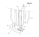
- FIG. 2 is an enlarged view of the vicinity of a tip 22 of a center electrode 20 of a spark plug 100.
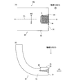
- FIG. It is explanatory drawing which expands and shows the front-end
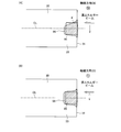
- FIG. 10 is an explanatory diagram showing another example of the formation process of the melting part 98 and an explanatory diagram showing an example of a change in the output of the high energy beam in the formation process of the melting part 98.
- FIG. 1 is a partial cross-sectional view of a spark plug 100 as an embodiment of the present invention.
- the axial direction OD of the spark plug 100 will be described as the vertical direction in the drawing, the lower side will be described as the front end side of the spark plug 100, and the upper side will be described as the rear end side.
- the spark plug 100 includes an insulator 10, a metal shell 50, a center electrode 20, a ground electrode 30, and a terminal metal fitting 40.
- the center electrode 20 is held in the insulator 10 in a state extending in the axial direction OD.
- the insulator 10 functions as an insulator, and the metal shell 50 holds the insulator 10.
- the terminal fitting 40 is provided at the rear end portion of the insulator 10. The configuration of the center electrode 20 and the ground electrode 30 will be described in detail with reference to FIG.
- the insulator 10 is formed by firing alumina or the like, and has a cylindrical shape in which an axial hole 12 extending in the axial direction OD is formed at the axial center.
- a flange portion 19 having the largest outer diameter is formed substantially at the center in the axial direction OD, and a rear end side body portion 18 is formed on the rear end side (upper side in FIG. 1).
- a front end side body portion 17 having a smaller outer diameter than the rear end side body portion 18 is formed on the front end side from the flange portion 19 (lower side in FIG. 1), and further, on the front end side from the front end side body portion 17,
- a leg length portion 13 having an outer diameter smaller than that of the distal end side body portion 17 is formed.
- the long leg portion 13 is reduced in diameter toward the tip side, and is exposed to the combustion chamber when the spark plug 100 is attached to the engine head 200 of the internal combustion engine.
- a step portion 15 is formed between the long leg portion 13 and the front end side body portion 17.
- the main metal fitting 50 is a cylindrical metal fitting made of a low carbon steel material, and fixes the spark plug 100 to the engine head 200 of the internal combustion engine.
- the metal shell 50 holds the insulator 10 inside, and the insulator 10 is surrounded by the metal shell 50 in a portion from a part of the rear end side body portion 18 to the leg length portion 13.
- the metal shell 50 includes a tool engaging portion 51 and a mounting screw portion 52.
- the tool engaging part 51 is a part into which a spark plug wrench (not shown) is fitted.
- the mounting screw portion 52 of the metal shell 50 is a portion where a screw thread is formed, and is screwed into a mounting screw hole 201 of the engine head 200 provided in the upper part of the internal combustion engine.
- a bowl-shaped seal portion 54 is formed between the tool engaging portion 51 and the mounting screw portion 52 of the metal shell 50.
- An annular gasket 5 formed by bending a plate is fitted into a screw neck 59 between the attachment screw portion 52 and the seal portion 54.
- the gasket 5 is crushed and deformed between the seat surface 55 of the seal portion 54 and the opening peripheral edge portion 205 of the attachment screw hole 201. Due to the deformation of the gasket 5, the gap between the spark plug 100 and the engine head 200 is sealed, and airtight leakage in the engine through the mounting screw hole 201 is prevented.
- a thin caulking portion 53 is provided on the rear end side of the metal fitting 50 from the tool engaging portion 51.
- a thin buckled portion 58 is provided between the seal portion 54 and the tool engaging portion 51, similarly to the caulking portion 53.
- annular ring members 6 and 7 are interposed between the inner peripheral surface of the metal shell 50 from the tool engaging portion 51 to the caulking portion 53 and the outer peripheral surface of the rear end side body portion 18 of the insulator 10.
- annular ring members 6 and 7 are interposed between the ring members 6 and 7.
- talc talc
- the step part 15 of the insulator 10 is supported by the step part 56 formed in the inner periphery of the metal shell 50, and the metal shell 50 and the insulator 10 are integrated.
- the airtightness between the metal shell 50 and the insulator 10 is maintained by the annular plate packing 8 interposed between the step portion 15 of the insulator 10 and the step portion 56 of the metal shell 50, and is burned. Gas outflow is prevented.
- the buckling portion 58 is configured to bend outwardly and deform as the compression force is applied during caulking, and increases the airtightness in the metal shell 50 by earning a compression stroke of the talc 9. .
- a clearance CLR having a predetermined dimension is provided between the front end side of the stepped portion 56 of the metal shell 50 and the insulator 10.
- FIG. 2 is an enlarged view of the vicinity of the tip 22 of the center electrode 20 of the spark plug 100.
- the center electrode 20 is a rod-shaped electrode having a structure in which a core material 25 is embedded in an electrode base material 21.
- the electrode base material 21 is made of nickel such as Inconel (trade name) 600 or 601 or an alloy containing nickel as a main component.
- the core material 25 is made of copper or an alloy containing copper as a main component, which is superior in thermal conductivity to the electrode base material 21.
- the center electrode 20 is produced by filling a core material 25 inside an electrode base material 21 formed in a bottomed cylindrical shape, and performing extrusion molding from the bottom side and stretching it.
- the core member 25 has a substantially constant outer diameter at the body portion, but a reduced diameter portion is formed at the distal end side.
- the center electrode 20 extends in the shaft hole 12 toward the rear end side, and is electrically connected to the terminal fitting 40 (FIG. 1) via the seal body 4 and the ceramic resistor 3 (FIG. 1). Has been.
- a high voltage cable (not shown) is connected to the terminal fitting 40 via a plug cap (not shown), and a high voltage is applied.
- the front end portion 22 of the center electrode 20 protrudes from the front end portion 11 of the insulator 10.
- a center electrode tip 90 is bonded to the tip of the tip portion 22 of the center electrode 20.
- the center electrode tip 90 has a substantially cylindrical shape extending in the axial direction OD, and is formed of a noble metal having a high melting point in order to improve the spark wear resistance.
- the center electrode tip 90 may be, for example, iridium (Ir), one of the main components of platinum (Pt), rhodium (Rh), ruthenium (Ru), palladium (Pd), and rhenium (Re). It is formed of an Ir alloy to which two or more kinds are added.
- the ground electrode 30 is made of a metal having high corrosion resistance, and is made of, for example, a nickel alloy such as Inconel (trade name) 600 or 601.
- the base 32 of the ground electrode 30 is joined to the tip 57 of the metal shell 50 by welding.
- the ground electrode 30 is bent, and the tip portion 33 of the ground electrode 30 faces the tip surface 92 of the center electrode tip 90.
- a ground electrode tip 95 is joined to the tip 33 of the ground electrode 30 via a melting part 98.
- the discharge surface 96 of the ground electrode tip 95 faces the tip surface 92 of the center electrode tip 90, and there is a gap G between the discharge surface 96 of the ground electrode tip 95 and the tip surface 92 of the center electrode tip 90. Is formed.
- the ground electrode tip 95 can be formed of the same material as the center electrode tip 90.
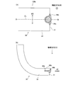
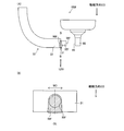
- FIG. 3 (A) is a view of the tip 33 of the ground electrode 30 as viewed from the direction along the axial direction OD.
- FIG. 3B is a diagram showing a BB cross section in FIG.
- the ground electrode chip 95 is embedded in a groove formed in the ground electrode 30.
- a melting portion 98 is formed at least at a part between the ground electrode tip 95 and the ground electrode 30.
- the melting portion 98 is formed by melting a part of the ground electrode tip 95 and a part of the ground electrode 30, and includes both the components of the ground electrode tip 95 and the ground electrode 30. That is, the melting part 98 has an intermediate composition between the ground electrode 30 and the ground electrode tip 95.
- the melting part 98 is not visible from the direction along the axial direction OD, but for the sake of explanation, the melting part 98 is also depicted in FIG. The same applies to the drawings shown below.
- a broken line is drawn between the ground electrode tip 95 and the ground electrode 30, actually, the ground electrode tip 95 and the ground electrode 30 are integrally formed in a portion where the melting portion 98 is formed. It is melted and the broken line disappears. The same applies to the drawings shown below.
- the melting part 98 can be formed by irradiating a high energy beam from a direction LD substantially parallel to the boundary between the ground electrode 30 and the ground electrode tip 95.
- a fiber laser or an electron beam is preferably used as the high energy beam for forming the melting portion 98.
- the boundary between the ground electrode 30 and the ground electrode tip 95 can be melted deeply, so that the ground electrode 30 and the ground electrode tip 95 can be firmly bonded.
- the area of the portion where the ground electrode 30 and the ground electrode tip 95 overlap is S.
- the melting part 98 is projected in a direction perpendicular to the discharge surface 96 of the ground electrode chip 95 (that is, the axial direction OD)
- 80% or more of the area S overlaps with the projected melting part 98. It is preferable. In this way, the generation of oxide scale in the vicinity of the melting part 98 can be suppressed. The basis for this will be described later.
- 100% of the area S overlaps with the melting part 98.
- the ratio of the portion overlapping the melted portion 98 in the area S is also referred to as “melted portion overlapping rate LR (%)”.
- a line perpendicular to the width direction WD of the ground electrode 30 and passing through the center of the ground electrode chip 95 is defined as a center line CL.
- the shape of the melting part 98 when viewed from the direction perpendicular to the discharge surface 96 of the ground electrode chip 95 (axial direction OD) is substantially symmetric with respect to the center line CL.
- the distribution of the thermal stress generated in the ground electrode 30 and the ground electrode chip 95 can be made symmetric with respect to the center line CL, and the difference between the thermal stresses on the left and right with respect to the center line CL is almost equal. Can be zero. Therefore, it can suppress that welding strength falls by the difference of the thermal stress of right and left.
- FIG. 4 is an explanatory view showing an example of the formation process of the melted portion 98.
- a high energy beam is irradiated while moving relative to the boundary between the ground electrode 30 and the ground electrode tip 95 ( FIG. 4 (A)).
- the melted portion 98 that is first irradiated with the high-energy beam has insufficient melting depth, and the melted portion 98 is shown in FIG. 3 (A). It does not become such a substantially symmetrical shape.
- the portion of the melted portion 98 that was initially irradiated with the high energy beam is not yet sufficiently heated by the high energy beam, and the temperature is not high enough to obtain a sufficient melting depth. It is thought that. Therefore, as shown in FIG. 4B, the high energy beam is reciprocated to the portion of the melting portion 98 where the melting depth is insufficient, and the high energy beam is irradiated twice. If it carries out like this, the melting depth of the part which the melting depth of the melting part 98 was insufficient will be supplemented, and the shape of the melting part 98 can be made into a substantially symmetrical shape.
- melting part 98 does not become a substantially symmetrical shape even if it irradiates a high energy beam twice, it is good also as irradiating a high energy beam 3 times or more.
- the high energy beam is moved, but the boundary between the ground electrode 30 and the ground electrode tip 95 may be moved with respect to the high energy beam.
- the high energy beam may be emitted before being irradiated to the boundary between the ground electrode 30 and the ground electrode tip 95. In this way, since the formation of the melted portion can be started after the output of the high energy beam becomes stable, the accuracy in forming the shape of the melted portion can be improved.
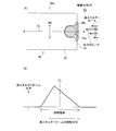
- FIG. 5A is an explanatory diagram showing another example of the process of forming the melted portion 98.
- FIG. 5B is an explanatory diagram showing an example of a change in the output of the high energy beam in the process of forming the melting portion 98.
- a portion of the melting portion 98 that is initially irradiated with the high energy beam has not yet been sufficiently heated, so that the melting depth may be insufficient. Therefore, in order to make the melted portion 98 substantially symmetrical with respect to the center line CL, the output of the high energy beam is changed with relative movement. Specifically, for example, as shown in FIG.
- the high energy beam is set to a constant value with a large output, the irradiated portion is sufficiently heated, and then the output of the high energy beam is gradually reduced. do it.
- the reason why the melted portion 98 can be made substantially symmetrical with respect to the center line CL even if the output of the high energy beam is gradually reduced is that the heat given by the high energy beam causes the melted portion 98 to gradually move. This is because the temperature of the portion that is conducted and not yet irradiated with the high-energy beam also increases. Therefore, if the output of the high energy beam is changed with the relative movement, the melting part 98 can be made substantially symmetrical with respect to the center line CL.
- the output waveform of the high energy beam for making the melted portion 98 substantially symmetric with respect to the center line CL is not limited to the output waveform shown in FIG. 5B, and the ground electrode 30 and the ground electrode chip. It is preferable to adjust the output of the high-energy beam according to the material and shape of 95.
- the oxide scale ratio is the ratio of the length of the oxide scale to the length of the contour line in the cross-sectional shape (FIG. 3B) of the melting portion 98.
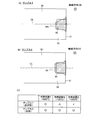
- FIG. 6 (A) is a view showing the vicinity of the tip of the spark plug of Sample 1 used in the cooling test.
- FIG. 6B is a diagram showing the vicinity of the tip of the spark plug of Sample 2 used in the cooling test.
- the melted portion 98x has an asymmetric shape with respect to the center line CL.
- the melting part 98 has a substantially symmetrical shape with respect to the center line CL, as in the first embodiment shown in FIG.
- a criterion for determining whether or not the melted portion 98 has a substantially symmetric shape with respect to the center line CL will be described later.
- the ground electrode 30 was heated with a burner for 2 minutes to raise the temperature of the ground electrode 30 to 1000 ° C. Thereafter, the burner was turned off, the ground electrode 30 was gradually cooled for 1 minute, and the ground electrode 30 was heated again with the burner for 2 minutes to raise the temperature of the ground electrode 30 to 1000 ° C. This cycle was repeated 1000 times, and the length of the oxide scale generated in the vicinity of the melted portion was measured from the judgment surface. And the oxide scale ratio was calculated
- the test conditions of the cooling test 2 are the same as those of the cooling test 1 except that the temperature of the ground electrode 30 is raised to 1100 ° C.
- the test conditions of the cooling test 3 are the same as those of the cooling test 1 except that the temperature of the ground electrode 30 is increased to 1200 ° C.
- FIG. 6C is a table showing the results of the cooling test.
- the case where the oxide scale ratio was less than 30% was evaluated as ⁇
- the case where it was 30% or more and less than 50% was evaluated as ⁇
- the case where it was 50% or more was evaluated as.
- the evaluation in the cooling test 1 is “good”, but the evaluation in the cooling test 2 is ⁇ , and in the cooling test 3, the evaluation was negative. The reason for this will be described.
- the distribution of the thermal stress generated in the vicinity of the melted part 98x is asymmetric with respect to the center line CL.
- the difference between the thermal stresses on the left and right across the center line CL increases, the bonding strength between the ground electrode 30 and the ground electrode tip 95 decreases, and oxide scale is likely to occur near the melted portion 98x. Conceivable.
- the evaluation in each of the thermal tests 1 to 3 was “good”. The reason for this will be described. Since the shape of the melting part 98 is substantially symmetric with respect to the center line CL, the distribution of thermal stress generated in the vicinity of the melting part 98 is substantially symmetric with respect to the center line CL. As a result, the difference between the thermal stresses on the left and right across the center line CL is substantially zero, so that the bonding strength between the ground electrode 30 and the ground electrode tip 95 can be sufficiently ensured. For this reason, it is considered that oxide scale is less likely to occur in the vicinity of the melting portion 98. Therefore, it can be understood that the shape of the melted portion is preferably substantially symmetric with respect to the center line CL.
- Example of experiment on melt overlap rate In order to investigate the relationship between the above-described melted portion overlap rate LR and the oxide scale ratio, the above-described cooling test 2 was performed using a plurality of samples having different melted portion overlap rates.
- FIG. 7 is a diagram showing the results of the cooling test. According to FIG. 7, it can be understood that the oxide scale ratio decreases as the fusion zone overlap ratio LR increases. Furthermore, it can be understood that when the melted portion overlap ratio LR is 80% or more, the oxide scale ratio is less than 50%. The reason for this is considered to be that as the melted portion overlap ratio LR increases, the bonding strength between the ground electrode 30 and the ground electrode tip 95 can be increased, and oxide scale is less likely to occur in the vicinity of the melted portion 98. Therefore, as in the above embodiment, it is preferable that the fusion zone overlap ratio LR is 80% or more.
- FIG. 8 is an explanatory view showing, in an enlarged manner, the vicinity of the tip of the spark plug 100b in another embodiment.
- FIG. 8A is a view of the ground electrode 30 as viewed from the direction along the axial direction OD.
- FIG. 8B is a diagram showing a BB cross section in FIG. This embodiment is different from the first embodiment (FIG. 3) in that the ground electrode tip 95b has a substantially cylindrical shape and the ground electrode tip 95b protrudes from the distal end surface 31 of the ground electrode 30.
- Other configurations are the same as those of the first embodiment. As described above, the ground electrode tip can have any shape.
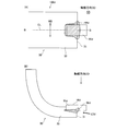
- FIG. 9 is an explanatory view showing, in an enlarged manner, the vicinity of the tip of the spark plug 100c according to another embodiment.
- FIG. 9A is a view of the ground electrode 30 as viewed from the direction along the axial direction OD.
- FIG. 9B is a diagram showing a BB cross section in FIG. This embodiment differs from the first embodiment (FIG. 3) in that the shape of the ground electrode tip 95c is a substantially cylindrical shape, and other configurations are the same as those in the first embodiment. As described above, the ground electrode tip can have any shape.
- FIG. 10 is an explanatory diagram showing an example of the formation process of the melted portion 98c in the spark plug 100c shown in FIG.
- FIG. 10B is an explanatory diagram showing an example of a change in the output of the high energy beam in the process of forming the melting portion 98c.
- the ground electrode tip 95c has a substantially cylindrical shape. Therefore, in order to make the shape of the melted portion 98c substantially symmetric with respect to the center line CL and along the arc of the outer periphery of the ground electrode tip 95c, the output of the high energy beam is accompanied by relative movement. It is preferable to change them. Specifically, for example, as shown in the arrow in FIG. 10A and FIG.
- the output of the high energy beam is increased up to the front of the center line CL, and then gradually decreased. That's fine. That is, the output of the high-energy beam is increased with relative movement, set to a peak value before the center line CL, and then the output is decreased more slowly than at the time of rising. Even if the output of the high energy beam is set to the peak value before the center line CL, the reason why the melting portion 98c can be made substantially symmetrical with respect to the center line CL is that the heat given by the high energy beam is melted. This is because the temperature of the portion that is gradually conducted through the portion 98c and has not yet been irradiated with the high energy beam becomes high.
- the melting part 98c has a shape that is substantially symmetrical with respect to the center line CL, and The shape may be along the arc of the ground electrode tip 95c.
- FIG. 11 is an explanatory view showing, in an enlarged manner, the vicinity of the tip of the spark plug 100d according to another embodiment.
- FIG. 11A is a view of the ground electrode 30 as viewed from the direction along the axial direction OD.
- FIG. 11B is a diagram showing a BB cross section in FIG. This embodiment is different from the first embodiment (FIG. 3) in that the ground electrode tip 95d has a larger amount of protrusion from the distal end surface 31 of the ground electrode 30, and a melting portion 98d is formed.
- a high energy beam is irradiated from a direction LD2 oblique to the boundary between the ground electrode 30 and the ground electrode chip 95d.
- Other configurations are the same as those of the first embodiment.
- the ground electrode tip can have any shape. Further, the high energy beam may be irradiated from an oblique direction with respect to the boundary between the ground electrode 30 and the ground electrode tip 95d.
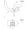
- FIG. 12 is an explanatory view showing, in an enlarged manner, the vicinity of the tip of the spark plug 100e in another embodiment.
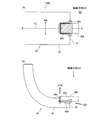
- FIG. 12A is a diagram of the ground electrode 30 viewed from a direction perpendicular to the axial direction OD.
- FIG. 12B is a diagram showing a BB cross section in FIG.
- the present embodiment is different from the first embodiment (FIG. 3) in that the ground electrode tip 95e is joined to the distal end surface 31 of the ground electrode 30, and the discharge surface 96e of the ground electrode tip 95e is the center electrode tip. It is a point facing 90 side surfaces 91. That is, the spark plug 100e is a so-called transverse discharge type spark plug.
- the fusion zone 98e is formed by irradiating a high energy beam from the direction LD3 parallel to the boundary between the ground electrode tip 95e and the ground electrode 30.
- the melting part 98e is perpendicular to the width direction WD of the ground electrode 30, and has a substantially symmetric shape with respect to the center line CL passing through the center of the ground electrode tip 95e. In this way, even in a horizontal discharge type spark plug, the difference in thermal stress between the left and right across the center line CL can be made substantially zero, so that the bonding strength between the ground electrode 30 and the ground electrode tip 95e is high. It can suppress that it falls.
- FIG. 13 is an explanatory view showing, in an enlarged manner, the vicinity of the tip of the spark plug 100f in another embodiment.
- FIG. 13A is a diagram of the ground electrode 30 viewed from a direction perpendicular to the axial direction OD.
- FIG. 13B is a diagram showing a BB cross section in FIG. This embodiment is different from the embodiment shown in FIG. 12 in that the shape of the ground electrode tip 95f is substantially cylindrical. Other configurations are the same as those of the embodiment shown in FIG. Thus, the shape of the ground electrode tip can be any shape.
- FIG. 14 is an explanatory view showing, in an enlarged manner, the vicinity of the tip of the spark plug 100g according to another embodiment.
- FIG. 14A is a view of the ground electrode 30 as viewed from the direction along the axial direction OD.
- FIG. 14B is a diagram showing a BB cross section in FIG. This embodiment is different from the embodiment shown in FIG. 9 in that the melted portion 99g is formed by irradiating a high energy beam from the direction LD4 along the axial direction OD.
- Other configurations are the same as those of the embodiment shown in FIG.
- the bonding strength between the ground electrode 30 and the ground electrode tip 95 can be further increased.
- FIG. 15 is an explanatory view showing, in an enlarged manner, the vicinity of the tip of the spark plug 100h in another embodiment.
- FIG. 15A is a view of the ground electrode 30 as viewed from the direction along the axial direction OD.
- FIG. 15B is a diagram showing a BB cross section in FIG.
- the present embodiment is different from the embodiment shown in FIG. 11 in that the fusion zone 99h is formed by irradiating a high energy beam from the direction LD4 along the axial direction OD.
- Other configurations are the same as those of the embodiment shown in FIG.
- the bonding strength between the ground electrode 30 and the ground electrode tip 95 can be further increased.
- FIG. 16 is an explanatory diagram showing a criterion for determining whether or not the melted portion is substantially symmetric with respect to the center line CL.
- FIG. 16 shows a state in which the melted part is cut along a plane perpendicular to the axial direction OD.
- whether or not the melted part is substantially symmetric with respect to the center line CL is determined by paying attention to an outer edge line indicating an outer edge of the cut surface of the melted part.
- the outer edge line located below the center line CL is defined as an outer edge line ML1
- the outer edge line located above the center line CL is defined as the outer edge line.
- a line along the outer side of the outer edge line ML1 by the allowable width SL is defined as an outer line AL1
- a line along the inner side of the outer edge line ML1 by the allowable width SL is defined as an inner line BL1.
- a line obtained by projecting the outer line AL1 symmetrically above the center line CL is referred to as an outer line AL2
- a line obtained by projecting the inner line BL1 symmetrically above the center line CL is referred to as an inner line BL2.
- the allowable width SL is 0.2 mm.
- the fusion part 98 is not substantially symmetric with respect to the center line CL. Is determined.
- the fusion part 98x is substantially symmetric with respect to the center line CL. judge.
- the outer edge line ML2 of the melted part 98x illustrated in FIG. 16A has a portion that passes through the inner side of the inner line BL2, the melted part 98x is approximately the center line CL. Judge that it is not symmetrical.
- the outer edge line ML2 of the fusion part 98 illustrated in FIG. 16B is all included in the region surrounded by the outer line AL2 and the inner line BL2, the fusion part 98 is located with respect to the center line CL. Are determined to be substantially symmetrical.
- the length of the allowable width SL is the size of the electrode tip, It can set suitably according to a shape.
- the length of the allowable width SL may be set to 20% of the long side of the electrode tip.
- the outer edge line ML1 on the lower side of the center line CL is used as the reference line. You may determine whether it is substantially symmetrical with respect to CL.
- the reference line may be determined based on the ideal shape of the melting part. The ideal shape is a shape obtained when the melted portion is melted at a sufficiently high temperature.
- the outer edge line ML1 below the center line CL is This condition is satisfied more than the upper outer edge line ML2.
- the reference line may be ideally obtained by simulation or the like.
- Buckling part 59 ... Screw neck 90 ... Center electrode tip 91 ... Side face 92 ... Tip surface 95 ... Ground electrode tip 95b ... Ground electrode tip 95c ... Ground electrode tip 95d ... Ground electrode tip 95e ... Ground electrode tip 95f ... Ground electrode tip 95g ... Ground electrode 95h ... Ground electrode tip 96 ... Discharge surface 96b ... Discharge surface 96c ... Discharge surface 96d ... Discharge surface 96e ... Discharge surface 96f ... Discharge surface 96g ... Discharge surface 96h ... Discharge surface 98 ... Melting part 98b ... Melting part 98c ... Melting part Part 98d ... Melting part 98e ... Melting part 98f ...
Landscapes
- Engineering & Computer Science (AREA)
- Manufacturing & Machinery (AREA)
- Spark Plugs (AREA)
Abstract
Description
軸線方向に貫通する軸孔を有する絶縁体と、
前記軸孔の先端側に設けられた中心電極と、
前記絶縁体を保持する略筒状の主体金具と、
一端部が前記主体金具の先端部に取り付けられ、他端が前記中心電極の先端部と対向する接地電極と、
前記接地電極の前記中心電極の先端部と対向する面に設けられ、前記中心電極との間で火花放電間隙を形成する放電面を有する貴金属チップと、
を備えるスパークプラグの製造方法であって、
前記接地電極と前記貴金属チップとの境界に対して高エネルギービームを照射することによって溶融部を形成する溶融部形成工程を備え、
前記溶融部形成工程では、
前記溶融部を前記放電面に垂直な方向に投影した場合に、前記接地電極と前記貴金属チップとが重なり合っている部分の面積のうちの80%以上の面積が、前記投影された溶融部と重なり合うように、
かつ、
前記放電面に垂直な方向から見た場合における前記溶融部の形状が、前記接地電極の幅方向に垂直であって前記貴金属チップの中心を通過する中心線に対して、略対称となるように、前記溶融部を形成する、スパークプラグの製造方法。
適用例1のスパークプラグの製造方法によれば、接地電極と貴金属チップとの境界に占める溶融部の面積が大きくなるため、接地電極と貴金属チップとの溶接強度を向上させたスパークプラグを製造することができる。さらに、溶融部の形状が中心線に対して略対称となるため、中心線を中心とした左右の熱応力の差をほぼゼロにすることができる。したがって、熱応力差による溶接強度の低下を抑制することができる。
適用例1に記載のスパークプラグの製造方法であって、
前記溶融部形成工程は、
前記高エネルギービームを前記境界に対して相対的に往復移動させながら照射し、前記境界の一部に対しては前記高エネルギービームを二度以上照射することによって、前記溶融部の形状を前記中心線に対して略対称とする工程を含むことを特徴とする、スパークプラグの製造方法。
適用例2のスパークプラグの製造方法によれば、貴金属チップの中心線に対して略対称な形状を有する溶融部を形成することができる。
適用例1または適用例2に記載のスパークプラグの製造方法であって、
前記溶融部形成工程は、
前記高エネルギービームを前記境界に対して相対的に移動させながら照射し、前記高エネルギービームの出力を前記相対移動に伴って変化させることによって、前記溶融部の形状を前記中心線に対して略対称とする工程を含むことを特徴とする、スパークプラグの製造方法。
適用例3のスパークプラグの製造方法によれば、貴金属チップの中心線に対して略対称な形状を有する溶融部を形成することができる。
適用例3に記載のスパークプラグの製造方法であって、
前記溶融部形成工程は、
前記高エネルギービームを前記境界に対して相対的に移動させながら照射し、前記高エネルギービームの出力を前記相対移動の開始後は一定とし、その後次第に前記高エネルギービームの出力を小さくすることによって、前記溶融部の形状を前記中心線に対して略対称とする工程を含むことを特徴とする、スパークプラグの製造方法。
適用例5のスパークプラグの製造方法によれば、略直方体形状のような貴金属チップの中心線に対して略対称な形状を有する溶融部を形成することができる。
適用例3に記載のスパークプラグの製造方法であって、
前記溶融部形成工程は、
前記高エネルギービームを前記境界に対して相対的に移動させながら照射し、前記高エネルギービームの出力を前記中心線の手前までは大きくしていき、その後、前記高エネルギービームの出力を徐々に小さくすることによって、前記溶融部の形状を前記中心線に対して略対称とする工程を含むことを特徴とする、スパークプラグの製造方法。
適用例5のスパークプラグの製造方法によれば、略円柱形状のような貴金属チップの中心線に対して略対称な形状を有する溶融部を形成することができる。
適用例1ないし適用例5のいずれか一項に記載のスパークプラグの製造方法であって、
前記溶融部形成工程は、
前記高エネルギービームは、前記境界に対して照射される前から照射されていることを特徴とする、スパークプラグの製造方法。
適用例6のスパークプラグの製造方法によれば、出力が安定した状態の高エネルギービームを境界に対して照射することができるので、溶融部の形状を形成する際の精度を向上させることができる。
適用例1ないし適用例6のいずれか一項に記載のスパークプラグの製造方法であって、
前記溶融部形成工程は、
前記境界で規定される面に対して平行な方向から前記高エネルギービームを照射する工程を含むことを特徴とする、スパークプラグの製造方法。
適用例7のスパークプラグの製造方法によれば、接地電極と貴金属チップの境界を適切に溶融させることができる。
適用例1ないし適用例7のいずれか一項に記載のスパークプラグの製造方法であって、
前記溶融部形成工程は、
前記境界で規定される面に対して斜めの方向から前記高エネルギービームを照射する工程を含むことを特徴とする、スパークプラグの製造方法。
適用例8のスパークプラグの製造方法によれば、接地電極と貴金属チップの境界を適切に溶融させることができる。
適用例1ないし適用例8のいずれか一項に記載のスパークプラグの製造方法であって、
前記高エネルギービームは、ファイバーレーザまたは電子ビームであることを特徴とする、スパークプラグの製造方法。
適用例9のスパークプラグの製造方法によれば、接地電極と貴金属チップの境界を奥深くまで適切に溶融させることができる。
A.第1実施形態:
B.酸化スケールの発生に関する実験例:
C.溶融部重なり率に関する実験例:
D.その他の実施形態:
E.溶融部が中心線に対して略対称か否かについての判定基準:
図1は、本発明の一実施形態としてのスパークプラグ100の部分断面図である。なお、図1において、スパークプラグ100の軸線方向ODを図面における上下方向とし、下側をスパークプラグ100の先端側、上側を後端側として説明する。
溶融部の形状と、酸化スケール割合との関係を調べるために、3種類の冷熱試験1,2,3を行なった。ここで、酸化スケール割合とは、溶融部98の断面形状(図3(B))における輪郭線の長さに対する酸化スケールの長さの割合である。
上述した溶融部重なり率LRと、酸化スケール割合との関係を調べるために、溶融部重なり率の異なる複数のサンプルを用いて、上述した冷熱試験2を行なった。
図8は、その他の実施形態におけるスパークプラグ100bの先端付近を拡大して示す説明図である。図8(A)は、接地電極30を、軸線方向ODに沿った方向から見た図である。図8(B)は、図8(A)におけるB-B断面を示す図である。本実施形態が、第1実施形態(図3)と異なる点は、接地電極チップ95bの形状が略円柱形となっている点と、接地電極チップ95bが接地電極30の先端面31から突出している点であり、その他の構成は第1実施形態と同じである。このように、接地電極チップは、任意の形状とすることができる。
図16は、溶融部が中心線CLに対して略対称か否かについての判定基準を示す説明図である。この図16は、軸線方向ODに垂直な平面で溶融部を切断した状態を示している。本明細書では、溶融部が中心線CLに対して略対称か否かについては、溶融部の切断面における外縁を示す外縁線に着目して判定する。
4…シール体
5…ガスケット
6…リング部材
8…板パッキン
9…タルク
10…絶縁碍子
11…先端部
12…軸孔
13…脚長部
15…段部
17…先端側胴部
18…後端側胴部
19…鍔部
20…中心電極
21…電極母材
22…先端部
25…芯材
30…接地電極
31…先端面
32…基部
33…先端部
40…端子金具
50…主体金具
51…工具係合部
52…取付ねじ部
53…加締部
54…シール部
55…座面
56…段部
57…先端部
58…座屈部
59…ねじ首
90…中心電極チップ
91…側面
92…先端面
95…接地電極チップ
95b…接地電極チップ
95c…接地電極チップ
95d…接地電極チップ
95e…接地電極チップ
95f…接地電極チップ
95g…接地電極チップ
95h…接地電極チップ
96…放電面
96b…放電面
96c…放電面
96d…放電面
96e…放電面
96f…放電面
96g…放電面
96h…放電面
98…溶融部
98b…溶融部
98c…溶融部
98d…溶融部
98e…溶融部
98f…溶融部
98g…溶融部
98h…溶融部
98x…溶融部
99g…溶融部
99h…溶融部
100…スパークプラグ
100b…スパークプラグ
100c…スパークプラグ
100d…スパークプラグ
100e…スパークプラグ
100f…スパークプラグ
100g…スパークプラグ
100h…スパークプラグ
200…エンジンヘッド
201…孔
205…開口周縁部
Claims (9)
- 軸線方向に貫通する軸孔を有する絶縁体と、
前記軸孔の先端側に設けられた中心電極と、
前記絶縁体を保持する略筒状の主体金具と、
一端部が前記主体金具の先端部に取り付けられ、他端が前記中心電極の先端部と対向する接地電極と、
前記接地電極の前記中心電極の先端部と対向する面に設けられ、前記中心電極との間で火花放電間隙を形成する放電面を有する貴金属チップと、
を備えるスパークプラグの製造方法であって、
前記接地電極と前記貴金属チップとの境界に対して高エネルギービームを照射することによって溶融部を形成する溶融部形成工程を備え、
前記溶融部形成工程では、
前記溶融部を前記放電面に垂直な方向に投影した場合に、前記接地電極と前記貴金属チップとが重なり合っている部分の面積のうちの80%以上の面積が、前記投影された溶融部と重なり合うように、
かつ、
前記放電面に垂直な方向から見た場合における前記溶融部の形状が、前記接地電極の幅方向に垂直であって前記貴金属チップの中心を通過する中心線に対して、略対称となるように、前記溶融部を形成する、スパークプラグの製造方法。 - 請求項1に記載のスパークプラグの製造方法であって、
前記溶融部形成工程は、
前記高エネルギービームを前記境界に対して相対的に往復移動させながら照射し、前記境界の一部に対しては前記高エネルギービームを二度以上照射することによって、前記溶融部の形状を前記中心線に対して略対称とする工程を含むことを特徴とする、スパークプラグの製造方法。 - 請求項1または請求項2に記載のスパークプラグの製造方法であって、
前記溶融部形成工程は、
前記高エネルギービームを前記境界に対して相対的に移動させながら照射し、前記高エネルギービームの出力を前記相対移動に伴って変化させることによって、前記溶融部の形状を前記中心線に対して略対称とする工程を含むことを特徴とする、スパークプラグの製造方法。 - 請求項3に記載のスパークプラグの製造方法であって、
前記溶融部形成工程は、
前記高エネルギービームを前記境界に対して相対的に移動させながら照射し、前記高エネルギービームの出力を前記相対移動の開始後は一定とし、その後次第に前記高エネルギービームの出力を小さくすることによって、前記溶融部の形状を前記中心線に対して略対称とする工程を含むことを特徴とする、スパークプラグの製造方法。 - 請求項3に記載のスパークプラグの製造方法であって、
前記溶融部形成工程は、
前記高エネルギービームを前記境界に対して相対的に移動させながら照射し、前記高エネルギービームの出力を前記中心線の手前までは大きくしていき、その後、前記高エネルギービームの出力を徐々に小さくすることによって、前記溶融部の形状を前記中心線に対して略対称とする工程を含むことを特徴とする、スパークプラグの製造方法。 - 請求項1ないし請求項5のいずれか一項に記載のスパークプラグの製造方法であって、
前記溶融部形成工程は、
前記高エネルギービームは、前記境界に対して照射される前から照射されていることを特徴とする、スパークプラグの製造方法。 - 請求項1ないし請求項6のいずれか一項に記載のスパークプラグの製造方法であって、
前記溶融部形成工程は、
前記境界で規定される面に対して平行な方向から前記高エネルギービームを照射する工程を含むことを特徴とする、スパークプラグの製造方法。 - 請求項1ないし請求項7のいずれか一項に記載のスパークプラグの製造方法であって、
前記溶融部形成工程は、
前記境界で規定される面に対して斜めの方向から前記高エネルギービームを照射する工程を含むことを特徴とする、スパークプラグの製造方法。 - 請求項1ないし請求項8のいずれか一項に記載のスパークプラグの製造方法であって、
前記高エネルギービームは、ファイバーレーザまたは電子ビームであることを特徴とする、スパークプラグの製造方法。
Priority Applications (4)
| Application Number | Priority Date | Filing Date | Title |
|---|---|---|---|
| CN201080014807.0A CN102379072B (zh) | 2009-03-31 | 2010-03-17 | 火花塞的制造方法 |
| EP10758189.4A EP2416461B1 (en) | 2009-03-31 | 2010-03-17 | Method of manufacturing sparkplugs |
| US13/138,720 US8506341B2 (en) | 2009-03-31 | 2010-03-17 | Method of manufacturing sparkplugs |
| JP2010533772A JP5319692B2 (ja) | 2009-03-31 | 2010-03-17 | スパークプラグの製造方法 |
Applications Claiming Priority (2)
| Application Number | Priority Date | Filing Date | Title |
|---|---|---|---|
| JP2009-084691 | 2009-03-31 | ||
| JP2009084691 | 2009-03-31 |
Publications (1)
| Publication Number | Publication Date |
|---|---|
| WO2010113404A1 true WO2010113404A1 (ja) | 2010-10-07 |
Family
ID=42827722
Family Applications (1)
| Application Number | Title | Priority Date | Filing Date |
|---|---|---|---|
| PCT/JP2010/001916 Ceased WO2010113404A1 (ja) | 2009-03-31 | 2010-03-17 | スパークプラグの製造方法 |
Country Status (6)
| Country | Link |
|---|---|
| US (1) | US8506341B2 (ja) |
| EP (1) | EP2416461B1 (ja) |
| JP (2) | JP5319692B2 (ja) |
| KR (1) | KR101550089B1 (ja) |
| CN (1) | CN102379072B (ja) |
| WO (1) | WO2010113404A1 (ja) |
Cited By (3)
| Publication number | Priority date | Publication date | Assignee | Title |
|---|---|---|---|---|
| JP2013041754A (ja) * | 2011-08-17 | 2013-02-28 | Ngk Spark Plug Co Ltd | スパークプラグ |
| JP2017174793A (ja) * | 2016-03-16 | 2017-09-28 | 日本特殊陶業株式会社 | 点火プラグ |
| DE102019115581A1 (de) | 2018-06-13 | 2019-12-19 | Ngk Spark Plug Co., Ltd. | Zündkerze |
Families Citing this family (6)
| Publication number | Priority date | Publication date | Assignee | Title |
|---|---|---|---|---|
| CN103155314B (zh) | 2010-09-29 | 2014-10-08 | 日本特殊陶业株式会社 | 火花塞 |
| WO2013126319A1 (en) * | 2012-02-23 | 2013-08-29 | Fram Group Ip Llc | Laser welded spark plug electrode and method of forming the same |
| JP6293107B2 (ja) * | 2015-12-03 | 2018-03-14 | 日本特殊陶業株式会社 | 点火プラグ |
| JP6871002B2 (ja) * | 2016-03-09 | 2021-05-12 | 日本特殊陶業株式会社 | レーザ溶接方法、溶接接合体の製造方法、スパークプラグ用の電極の製造方法、及びスパークプラグの製造方法 |
| EP3216552B1 (en) * | 2016-03-09 | 2018-12-12 | NGK Spark Plug Co., Ltd. | Laser welding methods, method of manufacturing a welded body, method of manufacturing electrode for spark plug, and method of manufacturing spark plug based on such laser welding methods |
| JP7430490B2 (ja) * | 2019-01-25 | 2024-02-13 | 日本特殊陶業株式会社 | 点火プラグ |
Citations (6)
| Publication number | Priority date | Publication date | Assignee | Title |
|---|---|---|---|---|
| JP2002231417A (ja) * | 2001-01-31 | 2002-08-16 | Ngk Spark Plug Co Ltd | スパークプラグの製造方法 |
| JP2002237365A (ja) * | 2001-02-08 | 2002-08-23 | Denso Corp | スパークプラグおよびその製造方法 |
| JP2004517459A (ja) * | 2001-01-24 | 2004-06-10 | ローベルト ボツシユ ゲゼルシヤフト ミツト ベシユレンクテル ハフツング | 点火プラグ電極の製造のための方法 |
| JP2007118078A (ja) * | 2005-09-30 | 2007-05-17 | Nissan Motor Co Ltd | レーザ溶接方法およびレーザ溶接装置 |
| JP2007265843A (ja) * | 2006-03-29 | 2007-10-11 | Ngk Spark Plug Co Ltd | 内燃機関用スパークプラグの製造方法 |
| WO2008123343A1 (ja) * | 2007-03-29 | 2008-10-16 | Ngk Spark Plug Co., Ltd. | スパークプラグの製造方法 |
Family Cites Families (14)
| Publication number | Priority date | Publication date | Assignee | Title |
|---|---|---|---|---|
| JPH0557466A (ja) * | 1991-09-03 | 1993-03-09 | Toyota Motor Corp | レーザ溶接装置 |
| JP2853109B2 (ja) * | 1992-07-27 | 1999-02-03 | 日本特殊陶業株式会社 | スパークプラグの製造方法 |
| JPH0737674A (ja) * | 1993-07-26 | 1995-02-07 | Ngk Spark Plug Co Ltd | スパークプラグ |
| JP3426051B2 (ja) * | 1995-04-27 | 2003-07-14 | 日本特殊陶業株式会社 | スパークプラグの製造方法 |
| JP3196601B2 (ja) * | 1995-10-11 | 2001-08-06 | 株式会社デンソー | 内燃機関用スパークプラグの製造方法 |
| JP3796849B2 (ja) * | 1996-10-07 | 2006-07-12 | 株式会社デンソー | スパークプラグおよびその製造方法 |
| JP3121309B2 (ja) * | 1998-02-16 | 2000-12-25 | 株式会社デンソー | 内燃機関用のスパークプラグ |
| JP4092889B2 (ja) * | 2000-07-10 | 2008-05-28 | 株式会社デンソー | スパークプラグ |
| US6997767B2 (en) * | 2003-03-28 | 2006-02-14 | Ngk Spark Plug Co., Ltd. | Method for manufacturing a spark plug, and spark plug |
| US7557495B2 (en) | 2005-11-08 | 2009-07-07 | Paul Tinwell | Spark plug having precious metal pad attached to ground electrode and method of making same |
| JP2008123343A (ja) * | 2006-11-14 | 2008-05-29 | Sharp Corp | ソフトウェア差分測定装置、ソフトウェア差分測定プログラム、およびソフトウェア差分測定プログラムを記録した記録媒体 |
| JP4402731B2 (ja) * | 2007-08-01 | 2010-01-20 | 日本特殊陶業株式会社 | 内燃機関用スパークプラグ及びスパークプラグの製造方法 |
| WO2010041733A1 (ja) * | 2008-10-10 | 2010-04-15 | 日本特殊陶業株式会社 | スパークプラグ及びその製造方法 |
| JP5173036B2 (ja) * | 2010-04-16 | 2013-03-27 | 日本特殊陶業株式会社 | 内燃機関用スパークプラグ及びスパークプラグの製造方法 |
-
2010
- 2010-03-17 KR KR1020117025720A patent/KR101550089B1/ko not_active Expired - Fee Related
- 2010-03-17 CN CN201080014807.0A patent/CN102379072B/zh active Active
- 2010-03-17 EP EP10758189.4A patent/EP2416461B1/en active Active
- 2010-03-17 JP JP2010533772A patent/JP5319692B2/ja active Active
- 2010-03-17 US US13/138,720 patent/US8506341B2/en active Active
- 2010-03-17 WO PCT/JP2010/001916 patent/WO2010113404A1/ja not_active Ceased
-
2013
- 2013-05-07 JP JP2013097954A patent/JP5475906B2/ja active Active
Patent Citations (6)
| Publication number | Priority date | Publication date | Assignee | Title |
|---|---|---|---|---|
| JP2004517459A (ja) * | 2001-01-24 | 2004-06-10 | ローベルト ボツシユ ゲゼルシヤフト ミツト ベシユレンクテル ハフツング | 点火プラグ電極の製造のための方法 |
| JP2002231417A (ja) * | 2001-01-31 | 2002-08-16 | Ngk Spark Plug Co Ltd | スパークプラグの製造方法 |
| JP2002237365A (ja) * | 2001-02-08 | 2002-08-23 | Denso Corp | スパークプラグおよびその製造方法 |
| JP2007118078A (ja) * | 2005-09-30 | 2007-05-17 | Nissan Motor Co Ltd | レーザ溶接方法およびレーザ溶接装置 |
| JP2007265843A (ja) * | 2006-03-29 | 2007-10-11 | Ngk Spark Plug Co Ltd | 内燃機関用スパークプラグの製造方法 |
| WO2008123343A1 (ja) * | 2007-03-29 | 2008-10-16 | Ngk Spark Plug Co., Ltd. | スパークプラグの製造方法 |
Cited By (5)
| Publication number | Priority date | Publication date | Assignee | Title |
|---|---|---|---|---|
| JP2013041754A (ja) * | 2011-08-17 | 2013-02-28 | Ngk Spark Plug Co Ltd | スパークプラグ |
| JP2017174793A (ja) * | 2016-03-16 | 2017-09-28 | 日本特殊陶業株式会社 | 点火プラグ |
| DE102019115581A1 (de) | 2018-06-13 | 2019-12-19 | Ngk Spark Plug Co., Ltd. | Zündkerze |
| US10784654B2 (en) | 2018-06-13 | 2020-09-22 | Ngk Spark Plug Co., Ltd. | Spark plug |
| DE102019115581B4 (de) | 2018-06-13 | 2025-03-13 | Niterra Co., Ltd. | Zündkerze |
Also Published As
| Publication number | Publication date |
|---|---|
| US8506341B2 (en) | 2013-08-13 |
| JP5475906B2 (ja) | 2014-04-16 |
| EP2416461A4 (en) | 2013-11-20 |
| KR101550089B1 (ko) | 2015-09-03 |
| CN102379072A (zh) | 2012-03-14 |
| KR20120003923A (ko) | 2012-01-11 |
| JP2013149631A (ja) | 2013-08-01 |
| EP2416461B1 (en) | 2019-05-08 |
| EP2416461A1 (en) | 2012-02-08 |
| US20120015578A1 (en) | 2012-01-19 |
| JP5319692B2 (ja) | 2013-10-16 |
| CN102379072B (zh) | 2014-04-30 |
| JPWO2010113404A1 (ja) | 2012-10-04 |
Similar Documents
| Publication | Publication Date | Title |
|---|---|---|
| JP5475906B2 (ja) | スパークプラグの製造方法 | |
| JP5192611B2 (ja) | スパークプラグ | |
| JP4619443B2 (ja) | スパークプラグ | |
| US9837799B2 (en) | Spark plug | |
| JP5576753B2 (ja) | スパークプラグの製造方法 | |
| KR101998536B1 (ko) | 스파크 플러그 | |
| JP5213782B2 (ja) | スパークプラグ | |
| JP4837688B2 (ja) | スパークプラグ | |
| JP5421212B2 (ja) | スパークプラグ | |
| JP2013118082A (ja) | スパークプラグ、及び、スパークプラグの製造方法 | |
| JP2017103131A (ja) | 点火プラグ | |
| JP2017111983A (ja) | 点火プラグ |
Legal Events
| Date | Code | Title | Description |
|---|---|---|---|
| WWE | Wipo information: entry into national phase |
Ref document number: 201080014807.0 Country of ref document: CN |
|
| WWE | Wipo information: entry into national phase |
Ref document number: 2010533772 Country of ref document: JP |
|
| 121 | Ep: the epo has been informed by wipo that ep was designated in this application |
Ref document number: 10758189 Country of ref document: EP Kind code of ref document: A1 |
|
| WWE | Wipo information: entry into national phase |
Ref document number: 2010758189 Country of ref document: EP |
|
| WWE | Wipo information: entry into national phase |
Ref document number: 13138720 Country of ref document: US |
|
| NENP | Non-entry into the national phase |
Ref country code: DE |
|
| ENP | Entry into the national phase |
Ref document number: 20117025720 Country of ref document: KR Kind code of ref document: A |