WO2010116528A1 - タンクおよびその製造方法 - Google Patents
タンクおよびその製造方法 Download PDFInfo
- Publication number
- WO2010116528A1 WO2010116528A1 PCT/JP2009/057357 JP2009057357W WO2010116528A1 WO 2010116528 A1 WO2010116528 A1 WO 2010116528A1 JP 2009057357 W JP2009057357 W JP 2009057357W WO 2010116528 A1 WO2010116528 A1 WO 2010116528A1
- Authority
- WO
- WIPO (PCT)
- Prior art keywords
- layer
- helical
- fiber bundle
- tank
- hoop
- Prior art date
- Legal status (The legal status is an assumption and is not a legal conclusion. Google has not performed a legal analysis and makes no representation as to the accuracy of the status listed.)
- Ceased
Links
Images




Classifications
-
- F—MECHANICAL ENGINEERING; LIGHTING; HEATING; WEAPONS; BLASTING
- F17—STORING OR DISTRIBUTING GASES OR LIQUIDS
- F17C—VESSELS FOR CONTAINING OR STORING COMPRESSED, LIQUEFIED OR SOLIDIFIED GASES; FIXED-CAPACITY GAS-HOLDERS; FILLING VESSELS WITH, OR DISCHARGING FROM VESSELS, COMPRESSED, LIQUEFIED, OR SOLIDIFIED GASES
- F17C13/00—Details of vessels or of the filling or discharging of vessels
- F17C13/06—Closures, e.g. cap, breakable member
-
- F—MECHANICAL ENGINEERING; LIGHTING; HEATING; WEAPONS; BLASTING
- F17—STORING OR DISTRIBUTING GASES OR LIQUIDS
- F17C—VESSELS FOR CONTAINING OR STORING COMPRESSED, LIQUEFIED OR SOLIDIFIED GASES; FIXED-CAPACITY GAS-HOLDERS; FILLING VESSELS WITH, OR DISCHARGING FROM VESSELS, COMPRESSED, LIQUEFIED, OR SOLIDIFIED GASES
- F17C1/00—Pressure vessels, e.g. gas cylinder, gas tank, replaceable cartridge
- F17C1/02—Pressure vessels, e.g. gas cylinder, gas tank, replaceable cartridge involving reinforcing arrangements
- F17C1/04—Protecting sheathings
- F17C1/06—Protecting sheathings built-up from wound-on bands or filamentary material, e.g. wires
-
- F—MECHANICAL ENGINEERING; LIGHTING; HEATING; WEAPONS; BLASTING
- F17—STORING OR DISTRIBUTING GASES OR LIQUIDS
- F17C—VESSELS FOR CONTAINING OR STORING COMPRESSED, LIQUEFIED OR SOLIDIFIED GASES; FIXED-CAPACITY GAS-HOLDERS; FILLING VESSELS WITH, OR DISCHARGING FROM VESSELS, COMPRESSED, LIQUEFIED, OR SOLIDIFIED GASES
- F17C1/00—Pressure vessels, e.g. gas cylinder, gas tank, replaceable cartridge
- F17C1/02—Pressure vessels, e.g. gas cylinder, gas tank, replaceable cartridge involving reinforcing arrangements
- F17C1/04—Protecting sheathings
-
- F—MECHANICAL ENGINEERING; LIGHTING; HEATING; WEAPONS; BLASTING
- F17—STORING OR DISTRIBUTING GASES OR LIQUIDS
- F17C—VESSELS FOR CONTAINING OR STORING COMPRESSED, LIQUEFIED OR SOLIDIFIED GASES; FIXED-CAPACITY GAS-HOLDERS; FILLING VESSELS WITH, OR DISCHARGING FROM VESSELS, COMPRESSED, LIQUEFIED, OR SOLIDIFIED GASES
- F17C2201/00—Vessel construction, in particular geometry, arrangement or size
- F17C2201/01—Shape
- F17C2201/0104—Shape cylindrical
- F17C2201/0109—Shape cylindrical with exteriorly curved end-piece
-
- F—MECHANICAL ENGINEERING; LIGHTING; HEATING; WEAPONS; BLASTING
- F17—STORING OR DISTRIBUTING GASES OR LIQUIDS
- F17C—VESSELS FOR CONTAINING OR STORING COMPRESSED, LIQUEFIED OR SOLIDIFIED GASES; FIXED-CAPACITY GAS-HOLDERS; FILLING VESSELS WITH, OR DISCHARGING FROM VESSELS, COMPRESSED, LIQUEFIED, OR SOLIDIFIED GASES
- F17C2201/00—Vessel construction, in particular geometry, arrangement or size
- F17C2201/05—Size
- F17C2201/056—Small (<1 m3)
-
- F—MECHANICAL ENGINEERING; LIGHTING; HEATING; WEAPONS; BLASTING
- F17—STORING OR DISTRIBUTING GASES OR LIQUIDS
- F17C—VESSELS FOR CONTAINING OR STORING COMPRESSED, LIQUEFIED OR SOLIDIFIED GASES; FIXED-CAPACITY GAS-HOLDERS; FILLING VESSELS WITH, OR DISCHARGING FROM VESSELS, COMPRESSED, LIQUEFIED, OR SOLIDIFIED GASES
- F17C2201/00—Vessel construction, in particular geometry, arrangement or size
- F17C2201/05—Size
- F17C2201/058—Size portable (<30 l)
-
- F—MECHANICAL ENGINEERING; LIGHTING; HEATING; WEAPONS; BLASTING
- F17—STORING OR DISTRIBUTING GASES OR LIQUIDS
- F17C—VESSELS FOR CONTAINING OR STORING COMPRESSED, LIQUEFIED OR SOLIDIFIED GASES; FIXED-CAPACITY GAS-HOLDERS; FILLING VESSELS WITH, OR DISCHARGING FROM VESSELS, COMPRESSED, LIQUEFIED, OR SOLIDIFIED GASES
- F17C2203/00—Vessel construction, in particular walls or details thereof
- F17C2203/01—Reinforcing or suspension means
- F17C2203/011—Reinforcing means
-
- F—MECHANICAL ENGINEERING; LIGHTING; HEATING; WEAPONS; BLASTING
- F17—STORING OR DISTRIBUTING GASES OR LIQUIDS
- F17C—VESSELS FOR CONTAINING OR STORING COMPRESSED, LIQUEFIED OR SOLIDIFIED GASES; FIXED-CAPACITY GAS-HOLDERS; FILLING VESSELS WITH, OR DISCHARGING FROM VESSELS, COMPRESSED, LIQUEFIED, OR SOLIDIFIED GASES
- F17C2203/00—Vessel construction, in particular walls or details thereof
- F17C2203/06—Materials for walls or layers thereof; Properties or structures of walls or their materials
- F17C2203/0602—Wall structures; Special features thereof
- F17C2203/0604—Liners
-
- F—MECHANICAL ENGINEERING; LIGHTING; HEATING; WEAPONS; BLASTING
- F17—STORING OR DISTRIBUTING GASES OR LIQUIDS
- F17C—VESSELS FOR CONTAINING OR STORING COMPRESSED, LIQUEFIED OR SOLIDIFIED GASES; FIXED-CAPACITY GAS-HOLDERS; FILLING VESSELS WITH, OR DISCHARGING FROM VESSELS, COMPRESSED, LIQUEFIED, OR SOLIDIFIED GASES
- F17C2203/00—Vessel construction, in particular walls or details thereof
- F17C2203/06—Materials for walls or layers thereof; Properties or structures of walls or their materials
- F17C2203/0602—Wall structures; Special features thereof
- F17C2203/0612—Wall structures
- F17C2203/0614—Single wall
- F17C2203/0619—Single wall with two layers
-
- F—MECHANICAL ENGINEERING; LIGHTING; HEATING; WEAPONS; BLASTING
- F17—STORING OR DISTRIBUTING GASES OR LIQUIDS
- F17C—VESSELS FOR CONTAINING OR STORING COMPRESSED, LIQUEFIED OR SOLIDIFIED GASES; FIXED-CAPACITY GAS-HOLDERS; FILLING VESSELS WITH, OR DISCHARGING FROM VESSELS, COMPRESSED, LIQUEFIED, OR SOLIDIFIED GASES
- F17C2203/00—Vessel construction, in particular walls or details thereof
- F17C2203/06—Materials for walls or layers thereof; Properties or structures of walls or their materials
- F17C2203/0602—Wall structures; Special features thereof
- F17C2203/0612—Wall structures
- F17C2203/0614—Single wall
- F17C2203/0621—Single wall with three layers
-
- F—MECHANICAL ENGINEERING; LIGHTING; HEATING; WEAPONS; BLASTING
- F17—STORING OR DISTRIBUTING GASES OR LIQUIDS
- F17C—VESSELS FOR CONTAINING OR STORING COMPRESSED, LIQUEFIED OR SOLIDIFIED GASES; FIXED-CAPACITY GAS-HOLDERS; FILLING VESSELS WITH, OR DISCHARGING FROM VESSELS, COMPRESSED, LIQUEFIED, OR SOLIDIFIED GASES
- F17C2203/00—Vessel construction, in particular walls or details thereof
- F17C2203/06—Materials for walls or layers thereof; Properties or structures of walls or their materials
- F17C2203/0634—Materials for walls or layers thereof
- F17C2203/0636—Metals
- F17C2203/0646—Aluminium
-
- F—MECHANICAL ENGINEERING; LIGHTING; HEATING; WEAPONS; BLASTING
- F17—STORING OR DISTRIBUTING GASES OR LIQUIDS
- F17C—VESSELS FOR CONTAINING OR STORING COMPRESSED, LIQUEFIED OR SOLIDIFIED GASES; FIXED-CAPACITY GAS-HOLDERS; FILLING VESSELS WITH, OR DISCHARGING FROM VESSELS, COMPRESSED, LIQUEFIED, OR SOLIDIFIED GASES
- F17C2203/00—Vessel construction, in particular walls or details thereof
- F17C2203/06—Materials for walls or layers thereof; Properties or structures of walls or their materials
- F17C2203/0634—Materials for walls or layers thereof
- F17C2203/0658—Synthetics
- F17C2203/0663—Synthetics in form of fibers or filaments
- F17C2203/0665—Synthetics in form of fibers or filaments radially wound
-
- F—MECHANICAL ENGINEERING; LIGHTING; HEATING; WEAPONS; BLASTING
- F17—STORING OR DISTRIBUTING GASES OR LIQUIDS
- F17C—VESSELS FOR CONTAINING OR STORING COMPRESSED, LIQUEFIED OR SOLIDIFIED GASES; FIXED-CAPACITY GAS-HOLDERS; FILLING VESSELS WITH, OR DISCHARGING FROM VESSELS, COMPRESSED, LIQUEFIED, OR SOLIDIFIED GASES
- F17C2203/00—Vessel construction, in particular walls or details thereof
- F17C2203/06—Materials for walls or layers thereof; Properties or structures of walls or their materials
- F17C2203/0634—Materials for walls or layers thereof
- F17C2203/0658—Synthetics
- F17C2203/0663—Synthetics in form of fibers or filaments
- F17C2203/0668—Synthetics in form of fibers or filaments axially wound
-
- F—MECHANICAL ENGINEERING; LIGHTING; HEATING; WEAPONS; BLASTING
- F17—STORING OR DISTRIBUTING GASES OR LIQUIDS
- F17C—VESSELS FOR CONTAINING OR STORING COMPRESSED, LIQUEFIED OR SOLIDIFIED GASES; FIXED-CAPACITY GAS-HOLDERS; FILLING VESSELS WITH, OR DISCHARGING FROM VESSELS, COMPRESSED, LIQUEFIED, OR SOLIDIFIED GASES
- F17C2203/00—Vessel construction, in particular walls or details thereof
- F17C2203/06—Materials for walls or layers thereof; Properties or structures of walls or their materials
- F17C2203/0634—Materials for walls or layers thereof
- F17C2203/0658—Synthetics
- F17C2203/0663—Synthetics in form of fibers or filaments
- F17C2203/067—Synthetics in form of fibers or filaments helically wound
-
- F—MECHANICAL ENGINEERING; LIGHTING; HEATING; WEAPONS; BLASTING
- F17—STORING OR DISTRIBUTING GASES OR LIQUIDS
- F17C—VESSELS FOR CONTAINING OR STORING COMPRESSED, LIQUEFIED OR SOLIDIFIED GASES; FIXED-CAPACITY GAS-HOLDERS; FILLING VESSELS WITH, OR DISCHARGING FROM VESSELS, COMPRESSED, LIQUEFIED, OR SOLIDIFIED GASES
- F17C2205/00—Vessel construction, in particular mounting arrangements, attachments or identifications means
- F17C2205/03—Fluid connections, filters, valves, closure means or other attachments
- F17C2205/0302—Fittings, valves, filters, or components in connection with the gas storage device
- F17C2205/0305—Bosses, e.g. boss collars
-
- F—MECHANICAL ENGINEERING; LIGHTING; HEATING; WEAPONS; BLASTING
- F17—STORING OR DISTRIBUTING GASES OR LIQUIDS
- F17C—VESSELS FOR CONTAINING OR STORING COMPRESSED, LIQUEFIED OR SOLIDIFIED GASES; FIXED-CAPACITY GAS-HOLDERS; FILLING VESSELS WITH, OR DISCHARGING FROM VESSELS, COMPRESSED, LIQUEFIED, OR SOLIDIFIED GASES
- F17C2205/00—Vessel construction, in particular mounting arrangements, attachments or identifications means
- F17C2205/03—Fluid connections, filters, valves, closure means or other attachments
- F17C2205/0388—Arrangement of valves, regulators, filters
- F17C2205/0394—Arrangement of valves, regulators, filters in direct contact with the pressure vessel
- F17C2205/0397—Arrangement of valves, regulators, filters in direct contact with the pressure vessel on both sides of the pressure vessel
-
- F—MECHANICAL ENGINEERING; LIGHTING; HEATING; WEAPONS; BLASTING
- F17—STORING OR DISTRIBUTING GASES OR LIQUIDS
- F17C—VESSELS FOR CONTAINING OR STORING COMPRESSED, LIQUEFIED OR SOLIDIFIED GASES; FIXED-CAPACITY GAS-HOLDERS; FILLING VESSELS WITH, OR DISCHARGING FROM VESSELS, COMPRESSED, LIQUEFIED, OR SOLIDIFIED GASES
- F17C2209/00—Vessel construction, in particular methods of manufacturing
- F17C2209/21—Shaping processes
- F17C2209/2154—Winding
-
- F—MECHANICAL ENGINEERING; LIGHTING; HEATING; WEAPONS; BLASTING
- F17—STORING OR DISTRIBUTING GASES OR LIQUIDS
- F17C—VESSELS FOR CONTAINING OR STORING COMPRESSED, LIQUEFIED OR SOLIDIFIED GASES; FIXED-CAPACITY GAS-HOLDERS; FILLING VESSELS WITH, OR DISCHARGING FROM VESSELS, COMPRESSED, LIQUEFIED, OR SOLIDIFIED GASES
- F17C2209/00—Vessel construction, in particular methods of manufacturing
- F17C2209/21—Shaping processes
- F17C2209/2154—Winding
- F17C2209/2163—Winding with a mandrel
-
- F—MECHANICAL ENGINEERING; LIGHTING; HEATING; WEAPONS; BLASTING
- F17—STORING OR DISTRIBUTING GASES OR LIQUIDS
- F17C—VESSELS FOR CONTAINING OR STORING COMPRESSED, LIQUEFIED OR SOLIDIFIED GASES; FIXED-CAPACITY GAS-HOLDERS; FILLING VESSELS WITH, OR DISCHARGING FROM VESSELS, COMPRESSED, LIQUEFIED, OR SOLIDIFIED GASES
- F17C2209/00—Vessel construction, in particular methods of manufacturing
- F17C2209/23—Manufacturing of particular parts or at special locations
- F17C2209/232—Manufacturing of particular parts or at special locations of walls
-
- F—MECHANICAL ENGINEERING; LIGHTING; HEATING; WEAPONS; BLASTING
- F17—STORING OR DISTRIBUTING GASES OR LIQUIDS
- F17C—VESSELS FOR CONTAINING OR STORING COMPRESSED, LIQUEFIED OR SOLIDIFIED GASES; FIXED-CAPACITY GAS-HOLDERS; FILLING VESSELS WITH, OR DISCHARGING FROM VESSELS, COMPRESSED, LIQUEFIED, OR SOLIDIFIED GASES
- F17C2209/00—Vessel construction, in particular methods of manufacturing
- F17C2209/23—Manufacturing of particular parts or at special locations
- F17C2209/234—Manufacturing of particular parts or at special locations of closing end pieces, e.g. caps
-
- F—MECHANICAL ENGINEERING; LIGHTING; HEATING; WEAPONS; BLASTING
- F17—STORING OR DISTRIBUTING GASES OR LIQUIDS
- F17C—VESSELS FOR CONTAINING OR STORING COMPRESSED, LIQUEFIED OR SOLIDIFIED GASES; FIXED-CAPACITY GAS-HOLDERS; FILLING VESSELS WITH, OR DISCHARGING FROM VESSELS, COMPRESSED, LIQUEFIED, OR SOLIDIFIED GASES
- F17C2221/00—Handled fluid, in particular type of fluid
- F17C2221/01—Pure fluids
- F17C2221/012—Hydrogen
-
- F—MECHANICAL ENGINEERING; LIGHTING; HEATING; WEAPONS; BLASTING
- F17—STORING OR DISTRIBUTING GASES OR LIQUIDS
- F17C—VESSELS FOR CONTAINING OR STORING COMPRESSED, LIQUEFIED OR SOLIDIFIED GASES; FIXED-CAPACITY GAS-HOLDERS; FILLING VESSELS WITH, OR DISCHARGING FROM VESSELS, COMPRESSED, LIQUEFIED, OR SOLIDIFIED GASES
- F17C2223/00—Handled fluid before transfer, i.e. state of fluid when stored in the vessel or before transfer from the vessel
- F17C2223/01—Handled fluid before transfer, i.e. state of fluid when stored in the vessel or before transfer from the vessel characterised by the phase
- F17C2223/0107—Single phase
- F17C2223/0123—Single phase gaseous, e.g. CNG, GNC
-
- F—MECHANICAL ENGINEERING; LIGHTING; HEATING; WEAPONS; BLASTING
- F17—STORING OR DISTRIBUTING GASES OR LIQUIDS
- F17C—VESSELS FOR CONTAINING OR STORING COMPRESSED, LIQUEFIED OR SOLIDIFIED GASES; FIXED-CAPACITY GAS-HOLDERS; FILLING VESSELS WITH, OR DISCHARGING FROM VESSELS, COMPRESSED, LIQUEFIED, OR SOLIDIFIED GASES
- F17C2223/00—Handled fluid before transfer, i.e. state of fluid when stored in the vessel or before transfer from the vessel
- F17C2223/03—Handled fluid before transfer, i.e. state of fluid when stored in the vessel or before transfer from the vessel characterised by the pressure level
- F17C2223/036—Very high pressure (>80 bar)
-
- F—MECHANICAL ENGINEERING; LIGHTING; HEATING; WEAPONS; BLASTING
- F17—STORING OR DISTRIBUTING GASES OR LIQUIDS
- F17C—VESSELS FOR CONTAINING OR STORING COMPRESSED, LIQUEFIED OR SOLIDIFIED GASES; FIXED-CAPACITY GAS-HOLDERS; FILLING VESSELS WITH, OR DISCHARGING FROM VESSELS, COMPRESSED, LIQUEFIED, OR SOLIDIFIED GASES
- F17C2260/00—Purposes of gas storage and gas handling
- F17C2260/01—Improving mechanical properties or manufacturing
- F17C2260/011—Improving strength
-
- F—MECHANICAL ENGINEERING; LIGHTING; HEATING; WEAPONS; BLASTING
- F17—STORING OR DISTRIBUTING GASES OR LIQUIDS
- F17C—VESSELS FOR CONTAINING OR STORING COMPRESSED, LIQUEFIED OR SOLIDIFIED GASES; FIXED-CAPACITY GAS-HOLDERS; FILLING VESSELS WITH, OR DISCHARGING FROM VESSELS, COMPRESSED, LIQUEFIED, OR SOLIDIFIED GASES
- F17C2270/00—Applications
- F17C2270/01—Applications for fluid transport or storage
-
- F—MECHANICAL ENGINEERING; LIGHTING; HEATING; WEAPONS; BLASTING
- F17—STORING OR DISTRIBUTING GASES OR LIQUIDS
- F17C—VESSELS FOR CONTAINING OR STORING COMPRESSED, LIQUEFIED OR SOLIDIFIED GASES; FIXED-CAPACITY GAS-HOLDERS; FILLING VESSELS WITH, OR DISCHARGING FROM VESSELS, COMPRESSED, LIQUEFIED, OR SOLIDIFIED GASES
- F17C2270/00—Applications
- F17C2270/01—Applications for fluid transport or storage
- F17C2270/0165—Applications for fluid transport or storage on the road
- F17C2270/0184—Fuel cells
-
- Y—GENERAL TAGGING OF NEW TECHNOLOGICAL DEVELOPMENTS; GENERAL TAGGING OF CROSS-SECTIONAL TECHNOLOGIES SPANNING OVER SEVERAL SECTIONS OF THE IPC; TECHNICAL SUBJECTS COVERED BY FORMER USPC CROSS-REFERENCE ART COLLECTIONS [XRACs] AND DIGESTS
- Y02—TECHNOLOGIES OR APPLICATIONS FOR MITIGATION OR ADAPTATION AGAINST CLIMATE CHANGE
- Y02E—REDUCTION OF GREENHOUSE GAS [GHG] EMISSIONS, RELATED TO ENERGY GENERATION, TRANSMISSION OR DISTRIBUTION
- Y02E60/00—Enabling technologies; Technologies with a potential or indirect contribution to GHG emissions mitigation
- Y02E60/30—Hydrogen technology
- Y02E60/32—Hydrogen storage
-
- Y—GENERAL TAGGING OF NEW TECHNOLOGICAL DEVELOPMENTS; GENERAL TAGGING OF CROSS-SECTIONAL TECHNOLOGIES SPANNING OVER SEVERAL SECTIONS OF THE IPC; TECHNICAL SUBJECTS COVERED BY FORMER USPC CROSS-REFERENCE ART COLLECTIONS [XRACs] AND DIGESTS
- Y10—TECHNICAL SUBJECTS COVERED BY FORMER USPC
- Y10T—TECHNICAL SUBJECTS COVERED BY FORMER US CLASSIFICATION
- Y10T29/00—Metal working
- Y10T29/49—Method of mechanical manufacture
- Y10T29/49826—Assembling or joining
- Y10T29/49863—Assembling or joining with prestressing of part
-
- Y—GENERAL TAGGING OF NEW TECHNOLOGICAL DEVELOPMENTS; GENERAL TAGGING OF CROSS-SECTIONAL TECHNOLOGIES SPANNING OVER SEVERAL SECTIONS OF THE IPC; TECHNICAL SUBJECTS COVERED BY FORMER USPC CROSS-REFERENCE ART COLLECTIONS [XRACs] AND DIGESTS
- Y10—TECHNICAL SUBJECTS COVERED BY FORMER USPC
- Y10T—TECHNICAL SUBJECTS COVERED BY FORMER US CLASSIFICATION
- Y10T428/00—Stock material or miscellaneous articles
- Y10T428/13—Hollow or container type article [e.g., tube, vase, etc.]
- Y10T428/1352—Polymer or resin containing [i.e., natural or synthetic]
- Y10T428/1369—Fiber or fibers wound around each other or into a self-sustaining shape [e.g., yarn, braid, fibers shaped around a core, etc.]
Definitions
- a tank used for storing hydrogen or the like a tank having an FRP layer in which hoop layers and helical layers are alternately stacked on the outer periphery of a liner is used (see, for example, Patent Document 1).
- the hoop layer is a layer formed by hoop-wrapping a bundle of fibers (for example, carbon fibers) (how to wind the tank body portion substantially perpendicularly to the tank axis), and the helical layer is made of CF (carbon fiber) or the like.
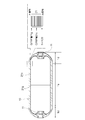
- the fiber bundle is a layer formed by helical winding (which is substantially parallel to the tank axis and wound to the tank dome) (see FIG. 2 of the present application).
- the fatigue strength of the layer adjacent to the outer side is reduced due to the step of the surface of the helical layer located in the inner layer of the FRP layer, particularly the innermost helical layer. There is a problem of lowering.
- the present invention has made it possible to avoid the phenomenon that the fatigue strength of the layer adjacent to the outside (particularly the hoop layer) is reduced due to the step difference of the surface of the helical layer located in the inner layer in the FRP layer. It is an object of the present invention to provide a tank having a structure and a manufacturing method thereof.
- the present inventor has made various studies and found that the fatigue strength in the hoop layer is reduced when the structural bending of the fiber bundle of the hoop layer is large. That is, when the FRP layer is formed by stacking the hoop layer and the helical layer, if the helical layer itself adjacent to the hoop layer has irregularities, the irregularities are transferred to the adjacent hoop layer, thereby The fiber bundle of the layer itself meanders to cause undulations, and bending (undulations) due to the structure occurs in the hoop layer.
- the present invention is based on such knowledge, and is a tank having a liner, and an FRP layer composed of a hoop layer and a helical layer that are alternately formed by winding a fiber bundle around the outer periphery of the liner, the FRP layer In at least one of the plurality of helical layers located in the inner layer, the cross-sectional area of the fiber bundle constituting the helical layer is equal to the cross-sectional area of the fiber bundle constituting the other layer formed outside the helical layer. Is smaller than that.
- the helical layer is wound so as to be substantially parallel to the tank axis and folded back at the tank dome (see FIG. 2), so as to eliminate a gap between adjacent fiber bundles. Since winding is not specifically considered, it is fundamentally difficult. In general, the helical layer is wound in a disorderly manner without considering the overlapping and arrangement of fiber bundles, and conventionally, for example, the phase of the reinforcing fiber bundles of each helical layer is shifted in the circumferential direction of the cylinder.
- the cross-sectional area of the fiber bundle constituting the helical layer is set to the other layer formed outside the helical layer.
- the unevenness in the helical layer is reduced. That is, when a helical layer is formed using a fiber bundle having a small cross-sectional area in this way, the thickness of the fiber bundle is reduced to that extent, and the height of the fiber bundle is lowered accordingly. Moreover, the gap between the fiber bundles is also reduced.
- a conventional helical layer (referred to as a helical layer that has not been subjected to a smoothing process and has irregularities on its surface, indicated by reference numeral 70B in FIGS. 11 and 12). It is possible to reduce the bending of the structural fiber bundle as described above. Therefore, by suppressing the structural bending (undulation) of the fiber bundle of the layer (for example, the hoop layer) formed outside the helical layer, The fatigue strength of the fiber bundle itself can be improved. It is also possible to improve the burst strength by reducing the thickness of the helical layer and the layer (for example, the hoop layer) formed outside the helical layer and increasing the Vf (fiber volume content).
- the helical layer located in the inner layer is preferably the innermost helical layer.
- the fiber bundle layer (helical layer, hoop layer) has a greater contribution to the tank strength as the inner layer (layer closer to the liner).
- the innermost helical layer is constituted by a fiber bundle having a small cross-sectional area as in the present invention
- the layer adjacent to the outer side of the innermost helical layer is wound more smoothly. Therefore, the structural bending (undulation) of the fiber bundle of the layer can be suppressed and the tank strength can be improved.
- the cross-sectional area of the fiber bundle is preferably changed by changing the number of fibers constituting the fiber bundle. In the case where a plurality of fibers are bundled to form a fiber bundle, if the number of fibers is reduced, the cross-sectional area of the fiber bundle can be reduced accordingly.
- the thickness of the fiber bundle in the stacking direction of the FRP layer is reduced by increasing the tension with respect to the fiber bundle constituting the helical layer. If the thickness of the fiber bundle is reduced and flattened, the unevenness in the helical layer is reduced accordingly, and the unevenness is transferred to another layer (for example, a hoop layer) formed outside the helical layer. It becomes possible to suppress.
- a fiber bundle composed of a fiber bundle having a diameter larger than that of the fiber bundle constituting the other layers as the fiber bundle constituting the other layer formed outside the helical layer.
- the manufacturing method according to the present invention is a method for manufacturing a tank having a liner and an FRP layer composed of a hoop layer and a helical layer that are alternately formed by winding a fiber bundle around the outer periphery of the liner.
- a cylinder according to the present invention is a cylinder having an FPR layer composed of hoop layers and helical layers alternately formed by winding a fiber bundle, and a plurality of helical layers located in an inner layer of the FRP layer
- the cross-sectional area of the fiber bundle constituting the helical layer is smaller than the cross-sectional area of the fiber bundle constituting the other layer formed outside the helical layer.
- the present invention it is possible to avoid the phenomenon that the fatigue strength of the layer adjacent to the outside (particularly the hoop layer) is reduced due to the step difference of the surface of the helical layer located in the inner layer in the FRP layer. Become.
- FIG. 1 to 4 show an embodiment of a tank and a manufacturing method thereof according to the present invention.
- the tank (henceforth a high pressure tank) 1 concerning this invention is applied to the high pressure hydrogen tank as a hydrogen fuel supply source.
- the hydrogen tank can be used in a fuel cell system or the like.
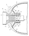
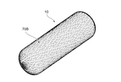
- the high-pressure tank 1 has, for example, a cylindrical tank body 10 having both ends substantially hemispherical, and a base 11 attached to one end of the tank body 10 in the longitudinal direction.
- the substantially hemispherical portion is referred to as a dome portion
- the cylindrical body portion is referred to as a straight portion, which are denoted by reference numerals 1d and 1s, respectively (see FIGS. 1 and 2).
- the high pressure tank 1 shown by this embodiment has the nozzle
- the tank body 10 has, for example, a two-layer wall layer, and has a liner 20 that is an inner wall layer and, for example, an FRP layer 21 that is a resin fiber layer (reinforcing layer) that is an outer wall layer on the outer side.
- the FRP layer 21 is formed of, for example, only the CFRP layer 21c, or the CFRP layer 21c and the GFRP layer 21g (see FIG. 1).
- the liner 20 is formed in substantially the same shape as the tank body 10.
- the liner 20 is made of, for example, polyethylene resin, polypropylene resin, or other hard resin.
- the liner 20 may be a metal liner formed of aluminum or the like.
- a folded portion 30 that is bent inward is formed on the tip end side of the liner 20 having the base 11.
- the folded portion 30 is folded toward the inside of the tank body 10 so as to be separated from the outer FRP layer 21.
- the folded portion 30 has, for example, a reduced diameter portion 30a that gradually decreases in diameter as it approaches the folded tip, and a cylindrical portion 30b that is connected to the distal end of the reduced diameter portion 30a and has a constant diameter.
- the cylindrical portion 30b forms an opening of the liner 20.
- the base 11 has a substantially cylindrical shape and is fitted into the opening of the liner 20.
- the base 11 is made of, for example, aluminum or an aluminum alloy, and is manufactured in a predetermined shape by, for example, a die casting method.
- the base 11 is fitted into an injection-molded split liner. Further, the base 11 may be attached to the liner 20 by insert molding, for example.
- the base 11 has a valve fastening seat surface 11a formed on the tip side (outside in the axial direction of the high pressure tank 1), for example, and on the rear side (inside in the axial direction of the high pressure tank 1) of the valve fastening seat surface 11a.
- An annular recess 11 b is formed with respect to the axis of the high-pressure tank 1.
- the dent 11b is convexly curved on the shaft side and has an R shape.
- the vicinity of the tip of the R-shaped FRP layer 21 is in airtight contact with the recess 11b.
- the surface of the recess 11b that contacts the FRP layer 21 is provided with a solid lubricating coating C such as a fluorine-based resin. Thereby, the friction coefficient between the FRP layer 21 and the recessed part 11b is reduced.
- the rear side of the recessed portion 11b of the base 11 is formed to fit, for example, the shape of the folded portion 30 of the liner 20, and for example, a flange portion (crest portion) 11c having a large diameter is formed continuously from the recessed portion 11b.
- a cap cylindrical portion 11d having a constant diameter is formed rearward from the flange portion 11c.
- the reduced diameter portion 30a of the folded portion 30 of the liner 20 is in close contact with the surface of the flange portion 11c, and the cylindrical portion 30b is in close contact with the surface of the cap cylindrical portion 11d. Seal members 40 and 41 are interposed between the cylindrical portion 30b and the base cylindrical portion 11d.
- the valve assembly 50 controls supply / discharge of fuel gas between an external gas supply line (supply path 22) and the inside of the high-pressure tank 1. Seal members 60 and 61 are interposed between the outer peripheral surface of the bubble assembly 50 and the inner peripheral surface of the base 11.
- the FRP layer 21 is formed by winding a fiber bundle (reinforcing fiber bundle) 70 impregnated with resin around the outer peripheral surface of the liner 20 and the recessed portion 11b of the base 11 by, for example, FW molding (filament winding molding), and curing the resin. It is formed by.
- a fiber bundle (reinforcing fiber bundle) 70 impregnated with resin around the outer peripheral surface of the liner 20 and the recessed portion 11b of the base 11 by, for example, FW molding (filament winding molding), and curing the resin. It is formed by.
- the resin of the FRP layer 21 for example, an epoxy resin, a modified epoxy resin, an unsaturated polyester resin, or the like is used.
- the fiber bundle 70 a bundle of carbon fiber (CF), metal fiber, or the like is used.
- the fiber bundle 70 can be wound around the outer peripheral surface of the liner 20 by moving the guide of the fiber bundle 70 along the tank axis direction while rotating the liner 20 around the tank axi
- the high-pressure tank 1 is formed by winding a fiber bundle (for example, a carbon fiber bundle) 70 around the outer periphery of the liner 20 and curing the resin.
- a fiber bundle for example, a carbon fiber bundle
- the hoop layer (indicated by reference numeral 70P in FIGS. 4 and 5, etc.) is formed by the layer in which the resin is hoop-wound, and the helically wound by the layer wound in the helical manner.
- Layers are respectively formed.
- the fiber bundle 70 is wound around the straight portion (tank body portion) of the high-pressure tank 1 like a coil spring, and the portion is tightened. Force to counteract the force to spread) to the liner 20.
- the latter helical winding is a winding method mainly intended to wind the dome portion in the tightening direction (inward in the tank axis direction), and the fiber bundle 70 is hooked on the dome portion to hold the fiber bundle 70 in the high-pressure tank 1.
- the overall wrapping contributes mainly to improving the strength of the dome.
- an acute angle (of which an acute angle is formed) between a string 70 of a fiber 70 wound like a coil spring (a thread line in a screw) and a center line of the tank 1 (tank shaft 12). 2) is the “winding angle with respect to the tank shaft (12)” of the fiber 70 referred to in the present specification, which is indicated by the symbol ⁇ in FIG.
- the hoop winding is a method in which the fiber bundle 70 is wound substantially perpendicularly to the tank axis in the straight portion, and the specific winding angle at that time is, for example, 80 to 90 ° (see FIG. 2). ).
- Helical winding (or impregnation winding) is a winding method in which the fiber bundle 70 is wound around the dome portion, and the winding angle with respect to the tank shaft is smaller than that in the case of hoop winding (see FIG. 2). If the helical winding is roughly divided into two types, there are two types, a high angle helical winding and a low angle helical winding.
- the high angle helical winding has a relatively large winding angle with respect to the tank shaft. ⁇ 80 °.
- the low-angle helical winding has a relatively small winding angle with respect to the tank shaft, and a specific example of the winding angle is 5 to 30 °.
- a helical winding at a winding angle of 30 to 70 ° between them may be referred to as a medium angle helical winding.
- the helical layers formed by the high angle helical winding, the medium angle helical winding, and the low angle helical winding are referred to as a high helical layer, a middle helical layer (indicated by reference numeral 70MH), and a low helical layer (indicated by reference numeral 70LH), respectively.
- the folded portion in the tank axial direction in the dome portion 1d of the high angle helical winding is referred to as a folded portion (see FIG. 2).
- the hoop winding is a winding method in which the fiber bundles 70 are wound spirally while adjoining each other, and the fiber bundles 70 are not stacked, so that unevenness is not generated.
- the helical winding is mainly intended to tighten the dome portion, and it is difficult to reduce the stacking and unevenness of the fiber bundle 70, or it is considered enough to reduce them. It is not how to wind.
- the hoop winding and the helical winding are appropriately combined according to specifications such as the axial length and diameter of the high-pressure tank 1, and the hoop layer 70P and the helical layer 70H are stacked around the liner 20 (see FIG. 1 and the like).
- the unevenness of the helical layer 70H is transferred to the hoop layer 70P, and the fiber bundle 70 of the hoop layer 70P may be bent (undulated).
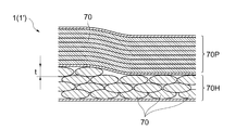
- the cross-sectional area of the fiber bundle 70 constituting the helical layer 70H is determined as the helical layer. It is made smaller than the cross-sectional area of the fiber bundle 70 which comprises the other layer formed in the outer side of 70H (refer FIG. 4).
- any of the plurality of helical layers 70H located in the inner layer can be targeted, but among these, the innermost helical layer (helical layer closest to the liner 20) 70H is targeted. It is preferable (see FIG. 6).
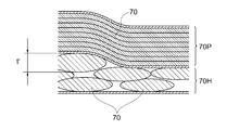
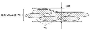
- the cross-sectional area of the fiber bundle 70 constituting the helical layer 70H is reduced. That is, when the helical layer 70H is formed using the fiber bundle 70 having a small cross-sectional area, the thickness t of the fiber bundle 70 itself becomes thinner than the conventional thickness t '(see FIGS. 4 and 5). Further, the wound fiber bundle 70 has a flat cross-sectional shape due to tension at the time of winding, pressure from other layers, and the like, and since the cross-sectional area is small, the interval between the fiber bundles 70 is larger than the conventional one.
- the state is narrowed (see FIG. 4). Therefore, since the helical layer 70H constituted by such a fiber bundle 70 has small irregularities on the surface thereof, other layers (in the case of the present embodiment, the hoop layer 70P) formed outside the helical layer 70H. ) Can be suppressed from being transferred (see FIG. 4). According to this, a conventional helical layer (referred to as a helical layer that has not been subjected to a smoothing process and has irregularities on its surface, indicated by reference numeral 70B in FIGS. 11 and 12). Therefore, the structural bending of the fiber bundle 70 of the layer (in the present embodiment, the hoop layer 70P) formed outside the helical layer 70H can be reduced.
- a conventional helical layer referred to as a helical layer that has not been subjected to a smoothing process and has irregularities on its surface, indicated by reference numeral 70B in FIGS. 11 and 12. Therefore, the structural bending of the fiber bundle 70 of the layer (in
- the surface of the helical layer 70P may not be smooth as a result of the overlapping of the fiber bundles 70 having relatively large cross-sectional areas (see FIG. 6).
- the surface of the helical layer 70H can be made smoother (see FIG. 4).
- the structural bending (undulation) of the hoop layer 70P formed outside the helical layer 70H is clearly smaller than in the conventional case (see FIGS. 4 and 5).
- Vf represents the fiber volume content.
- Vf value the fiber content increases and the resin content decreases. If the value of Vf is too high, fatigue durability deteriorates. If the value is too low, the outer shape of the tank becomes large.
- the innermost layer (innermost helical layer 70H) among the plurality of helical layers 70H located in the inner layer is targeted, so that there is an advantage that the tank strength can be further improved. That is, generally, the hoop layer 70P and the helical layer 70H (particularly the hoop layer 70P) formed by winding the fiber bundle 70 contribute to the tank strength as the inner layer (that is, the layer closer to the liner 20). Therefore, when the innermost helical layer 70H is constituted by the fiber bundle 70 having a small cross-sectional area as described above, a layer adjacent to the outer side of the innermost helical layer 70H (in the case of the present embodiment, a hoop layer). 70P) can be wound more smoothly. Thereby, structural bending (undulation) of the fiber bundle 70 which comprises the said hoop layer 70P can be suppressed, and it can contribute further to the improvement of tank strength.
- the “inner layer” in this specification refers to a layer closer to the liner 20 when the FRP layer 21 is divided into a plurality of parts.
- the inner layer when the FRP layer 21 is divided into three layers with the same thickness being 1/3 is called the inner layer
- the outer layer is the outer layer
- the intermediate layer is the inner layer. Called the middle layer.
- each layer is expressed as “outer”, “middle”, and “inner”.
- the cross-sectional area of the fiber bundle 70 can be changed by changing the number of fibers constituting the fiber bundle 70, for example.
- a fiber bundle (small tow) 70 having a small number of fibers is used for the helical layer 70H located in the inner layer of the FRP layer 21, and the other layers (the middle layer, the outer helical layer 70H, and the hoops of the entire layer) are used.
- the surface of the target helical layer 70H can be made smoother.
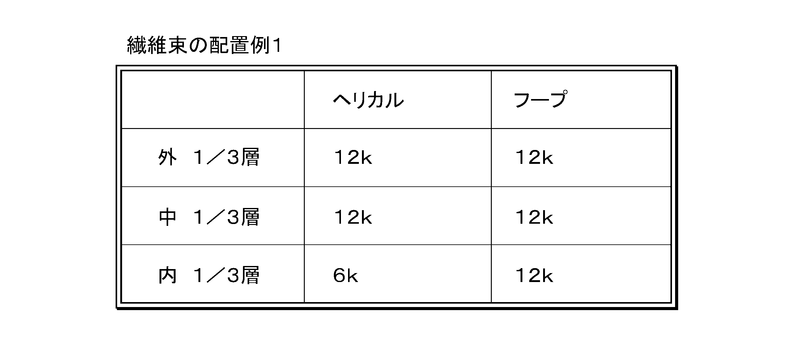
- An example of the arrangement of the fiber bundle 70 will be described as follows (see Tables 1 and 2).
- a fiber bundle 70 composed of 6k (6,000) fibers is used for the helical layer 70H located in the inner layer of the FRP layer 21, and the other layers (medium layer, outer layer helical layer)
- the fiber bundle 70 composed of 12k (12,000) fibers is used for 70H and the entire hoop layer 70P.
- the cross-sectional area of the fiber bundle 70 may be reduced for all of the helical layers 70H located in the inner layer, or the cross-sectional area of the fiber bundle 70 may be reduced for some of them.
- a fiber bundle 70 composed of 12k (12,000) fibers is used for the helical layer 70H located in the inner layer of the FRP layer 21, and other layers (the middle layer and the outer layer) are used.
- a fiber bundle 70 composed of 24k (24,000) fibers is used for the helical layer 70H and the entire hoop layer 70P. Even in this case, it is possible to appropriately change whether to reduce the cross-sectional area of the fiber bundle 70 for all of the helical layers 70H located in the inner layer or to reduce the cross-sectional area of the fiber bundle 70 for a part of them. is there.
- the mode of arrangement of the fiber bundle 70 described above is merely an example, and the number of fibers may be changed as appropriate.
- the cross-sectional area of the fiber bundle 70 of the target helical layer 70H is equal to the fiber bundle 70 of the other layers.
- the cross-sectional area is preferably 2/3 or less.
- the fiber bundle 70 is arranged after selecting so that the number of fibers of the fiber bundle 70 of the layer other than the target is 1.5 times or more than the number of fibers of the fiber bundle 70 of the target helical layer 70H. It is preferable to do.
- the thickness of the fiber bundle 70 in the stacking direction of the FRP layer 21 can be reduced by increasing the tension with respect to the fiber bundle constituting the helical layer 70H. In such a case, the fiber bundle 70 spreads in the width direction and becomes flatter, and the level difference is reduced and the surface of the helical layer 70H becomes smoother.
- the tension of the fiber bundle 70 is about 20 N at present (see FIG. 8), while the tension of the innermost helical layer 70H with respect to the fiber bundle 70 is 40 ⁇ . It is increased to about 50N (see FIG. 7).
- the fiber bundle 70 wound more strongly with an increase in tension has a flattened cross-sectional shape and a reduced thickness (thickness t ′ ⁇ t).
- the surface of the helical layer 70H becomes smoother by reducing the level difference (see FIG. 7).
- the thickness of the fiber bundle 70 and the thickness of the helical layer 70H are reduced by about 20%, and the surface is made smoother by reducing the unevenness. be able to.
- the tension when the tension is increased as described above to smooth the helical layer 70H, it is also preferable to increase the diameter of the fiber bundle 70 of the layer formed outside the helical layer 70H.
- the fiber bundle diameter of another layer for example, the hoop layer 70P
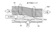
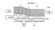
- the bending displacement in the fiber bundle is reduced, and the shear stress is reduced. It is possible to relax (see FIG. 9).
- a bending angle of, for example, 6 to 7 ° has occurred due to the unevenness of the helical layer 70H (see FIG. 10).
- the bending angle can be reduced to about 4.2 to 5.5 ° only by increasing the diameter of the fiber bundle 70 (see FIG. 9). That is, when the wire diameter of the fiber bundle 70 of the hoop layer 70P is increased in this way, the rigidity per fiber decreases, so that even when the same force is applied, the bending angle is reduced and the bending angle is reduced.
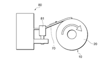
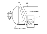
- the FW device 80 shown in FIGS. 13 and 14 reciprocates a guide device (referred to as an “eye opening”) 81 of the fiber bundle 70 along the tank axis direction while rotating the liner 20 around the tank axis.
- the fiber bundle 70 is wound around the outer periphery of the liner 20.
- the winding angle of the fiber bundle 70 can be changed by changing the relative speed of the movement of the guide device 81 with respect to the rotational speed of the liner 20.
- the guide device 81 is operably supported by a jig, for example.
- the unevenness and the structural bending that can be transferred to the layer adjacent to the outside of the helical layer 70H are reduced by reducing the unevenness on the surface of the helical layer 70H.
- the helical layer 70H is configured using the fiber bundle 70 having a small number of fibers and a relatively small cross-sectional area as described above, or the fiber bundle 70 It is effective to reduce the thickness t of the fiber bundle 70 by increasing the tension. It is also possible to increase the amount of fiber wound per unit time and improve the productivity of the high-pressure tank 1.
- the hoop layer 70P adjacent to the smooth helical layer 70H itself is made to have a high Vf (fiber volume content)
- the resin pool is reduced accordingly, so that it is used in the FRP layer 21. This leads to a decrease in the amount of resin.
- the amount of resin decreases, it is possible to reduce the weight of the high-pressure tank 1.
- the FRP layer 21 has a high Vf and the amount of resin decreases, the amount of heat generated by curing (heat generated by reaction heat during heat curing of the resin) decreases.
- the peak temperature at the time of thermosetting is high, problems such as bonding (a state in which the liner 20 and the FRP layer 21 are bonded partially or entirely after FW molding and resin curing) and liner material deterioration may occur.
- the high-pressure tank 1 of the present embodiment that can reduce the amount of heat generated by curing, it is possible to suppress these problems.
- the tank strength can be greatly improved. That is, reducing the structural bending of the fiber bundle 70 of the hoop layer 70 ⁇ / b> P is preferable in that it contributes to improving the fatigue strength of the straight portion 1 s of the high-pressure tank 1. Further, reducing the structural bending of the fiber bundle 70 of the helical layer 70H is preferable in that it contributes to improving the fatigue strength of the dome portion 1d of the high-pressure tank 1. In general, both the helical layer 70H and the hoop layer 70P have a greater contribution to the tank strength as the layers located closer to the inner side (layers closer to the liner 20), and in particular, the straight portion 1s is wound to sufficiently exert pressure resistance.
- the role of the innermost hoop layer 70P is great.
- a layer adjacent to the outer side of the smooth helical layer 70H (for example, the hoop layer 70P) can be formed smoothly.
- the layer (for example, the hoop layer 70P) can greatly contribute to the improvement of the tank strength.
- the above-described embodiment is an example of a preferred embodiment of the present invention, but is not limited thereto, and various modifications can be made without departing from the gist of the present invention.
- the innermost helical layer 70H is a smooth helical layer (innermost smooth helical layer)
- the same effect as described above can be realized also in the helical layer 70H.
- the case where the outer layer of the helical layer is the hoop layer 70P has been mainly described (see FIG. 4 and the like).
- the present embodiment is also applicable when the outer layer of the helical layer 70H is the helical layer 70H.
- the invention can be applied.
- the present invention is applied to a hydrogen tank that can be used in a fuel cell system and the like.
- the present invention is applied to a tank for filling a fluid other than hydrogen gas.
- a fluid other than hydrogen gas Of course it is also possible to do.
- the present invention can be applied to things other than a tank (pressure vessel), for example, a cylinder (including a cylindrical part) such as a long object or a structure having an FRP layer.
- a tank pressure vessel
- a cylinder including a cylindrical part
- the fiber bundle 70 is wound around a mandrel (such as a mandrel) or a mold by helical winding or hoop winding to form the FRP layer 21 having the helical layer 70H or the hoop layer 70P
- the helical layer 70H is formed, the same action as in the above-described embodiment, such as reducing the structural bending of the fiber bundle 70, improving the fatigue strength, and reducing the thickness per layer. An effect can be realized.
- the layer adjacent to the hoop layer is the other hoop layer 70 ⁇ / b> P or the smooth helical layer 70 ⁇ / b> H. Or it is also one of the preferable aspects to make the layer adjacent to the uneven
- the present invention is suitable for application to a tank having an FRP layer, and to a cylinder such as a long object or a structure.
Landscapes
- Engineering & Computer Science (AREA)
- Mechanical Engineering (AREA)
- General Engineering & Computer Science (AREA)
- Moulding By Coating Moulds (AREA)
- Filling Or Discharging Of Gas Storage Vessels (AREA)
- Pressure Vessels And Lids Thereof (AREA)
Abstract
Description

Claims (8)
- ライナと、該ライナの外周に繊維束が巻回されて交互に形成されるフープ層およびヘリカル層からなるFRP層と、を有するタンクであって、
前記FRP層の内層に位置する複数のヘリカル層のうちの少なくとも1つにおいて、該ヘリカル層を構成する繊維束の断面積が、当該ヘリカル層の外側に形成される他の層を構成する繊維束の断面積よりも小さい、タンク。 - 前記内層に位置するヘリカル層は、最内層のヘリカル層である、請求項1に記載のタンク。
- 前記ヘリカル層を構成する繊維束の断面積が、当該繊維束を構成する繊維数を変化させることにより変化している、請求項1に記載のタンク。
- 前記ヘリカル層を構成する繊維束に対する張力を増大させることにより前記FRP層の積層方向における当該繊維束の厚みを減少させている、請求項1から3のいずれか一項に記載のタンク。
- 当該ヘリカル層の外側に形成される前記他の層を構成する繊維束として、それ以外の層を構成する繊維束よりも太い径の繊維束で構成されたものを用いている、請求項1から4のいずれか一項に記載のタンク。
- 前記繊維束の断面積が小さいヘリカル層の外側に隣接して形成される他の層がフープ層である、請求項1から5のいずれか一項に記載のタンク。
- ライナと、該ライナの外周に繊維束が巻回されて交互に形成されるフープ層およびヘリカル層からなるFRP層と、を有するタンクの製造方法において、
前記FRP層の内層に位置する複数のヘリカル層のうちの少なくとも1つを、当該ヘリカル層の外側に形成される他の層を構成する繊維束の断面積よりも小さい断面積の繊維束を巻回することによって形成する、タンクの製造方法。 - 繊維束が巻回されて交互に形成されるフープ層およびヘリカル層からなるFPR層を有する筒体であって、
前記FRP層の内層に位置する複数のヘリカル層のうちの少なくとも1つにおいて、該ヘリカル層を構成する繊維束の断面積が、当該ヘリカル層の外側に形成される他の層を構成する繊維束の断面積よりも小さい、筒体。
Priority Applications (5)
| Application Number | Priority Date | Filing Date | Title |
|---|---|---|---|
| JP2011508170A JP5182597B2 (ja) | 2009-04-10 | 2009-04-10 | タンクおよびその製造方法 |
| CN200980158625.8A CN102388257B (zh) | 2009-04-10 | 2009-04-10 | 罐及其制造方法 |
| US13/263,640 US8740009B2 (en) | 2009-04-10 | 2009-04-10 | Tank and manufacturing method thereof |
| EP09843037.4A EP2418414B1 (en) | 2009-04-10 | 2009-04-10 | Tank and manufacturing method thereof |
| PCT/JP2009/057357 WO2010116528A1 (ja) | 2009-04-10 | 2009-04-10 | タンクおよびその製造方法 |
Applications Claiming Priority (1)
| Application Number | Priority Date | Filing Date | Title |
|---|---|---|---|
| PCT/JP2009/057357 WO2010116528A1 (ja) | 2009-04-10 | 2009-04-10 | タンクおよびその製造方法 |
Publications (1)
| Publication Number | Publication Date |
|---|---|
| WO2010116528A1 true WO2010116528A1 (ja) | 2010-10-14 |
Family
ID=42935836
Family Applications (1)
| Application Number | Title | Priority Date | Filing Date |
|---|---|---|---|
| PCT/JP2009/057357 Ceased WO2010116528A1 (ja) | 2009-04-10 | 2009-04-10 | タンクおよびその製造方法 |
Country Status (5)
| Country | Link |
|---|---|
| US (1) | US8740009B2 (ja) |
| EP (1) | EP2418414B1 (ja) |
| JP (1) | JP5182597B2 (ja) |
| CN (1) | CN102388257B (ja) |
| WO (1) | WO2010116528A1 (ja) |
Cited By (6)
| Publication number | Priority date | Publication date | Assignee | Title |
|---|---|---|---|---|
| JP2018114633A (ja) * | 2017-01-16 | 2018-07-26 | トヨタ自動車株式会社 | タンクの製造方法 |
| JP2018189178A (ja) * | 2017-05-09 | 2018-11-29 | 三菱ケミカル株式会社 | 圧力容器 |
| JP2020016289A (ja) * | 2018-07-25 | 2020-01-30 | トヨタ自動車株式会社 | 高圧タンク |
| JP2020169656A (ja) * | 2019-04-01 | 2020-10-15 | トヨタ自動車株式会社 | 高圧タンク及びその製造方法 |
| JP2021109427A (ja) * | 2020-01-15 | 2021-08-02 | トヨタ自動車株式会社 | 高圧タンクの製造方法 |
| JP2025068695A (ja) * | 2023-10-17 | 2025-04-30 | 本田技研工業株式会社 | 高圧タンク、その製造方法及びその製造装置 |
Families Citing this family (24)
| Publication number | Priority date | Publication date | Assignee | Title |
|---|---|---|---|---|
| FR2963659B1 (fr) * | 2010-08-03 | 2014-03-21 | Astrium Sas | Liaison entre liner metallique et structure composite dans la zone d'embase d'un reservoir |
| EP2679381B1 (en) * | 2011-02-21 | 2020-01-15 | Murata Machinery, Ltd. | Filament winding device |
| JP5999039B2 (ja) | 2013-07-10 | 2016-09-28 | トヨタ自動車株式会社 | 高圧タンクおよび高圧タンクの製造方法 |
| US11015761B1 (en) * | 2013-11-22 | 2021-05-25 | CleanNG, LLC | Composite pressure vessel for gas storage and method for its production |
| JP6769348B2 (ja) * | 2016-04-14 | 2020-10-14 | トヨタ自動車株式会社 | 高圧ガスタンクの製造方法 |
| KR20180017377A (ko) * | 2016-08-09 | 2018-02-21 | 현대자동차주식회사 | 고압 용기 |
| US10514129B2 (en) * | 2016-12-02 | 2019-12-24 | Amtrol Licensing Inc. | Hybrid tanks |
| DE102017208808A1 (de) | 2017-05-24 | 2018-11-29 | Bayerische Motoren Werke Aktiengesellschaft | Verfahren zur Herstellung eines Druckbehälters sowie Druckbehälter |
| KR102322373B1 (ko) * | 2017-05-26 | 2021-11-05 | 현대자동차주식회사 | 후프층 및 헬리컬층이 와인딩된 고압용기 |
| US10611565B2 (en) * | 2017-08-11 | 2020-04-07 | Christopher W. Housand | Refuse container protective liner and method of using the same |
| JP6630384B2 (ja) * | 2018-02-21 | 2020-01-15 | 本田技研工業株式会社 | 高圧タンク及びその製造方法 |
| JP7176287B2 (ja) * | 2018-08-09 | 2022-11-22 | トヨタ自動車株式会社 | 圧力容器及びその製造方法 |
| JP7351077B2 (ja) | 2018-09-28 | 2023-09-27 | トヨタ自動車株式会社 | 高圧タンク |
| JP7087907B2 (ja) | 2018-10-16 | 2022-06-21 | トヨタ自動車株式会社 | 高圧タンクおよび高圧タンクの製造方法 |
| JP7135727B2 (ja) * | 2018-10-30 | 2022-09-13 | トヨタ自動車株式会社 | 高圧タンク |
| JP7259734B2 (ja) * | 2019-12-25 | 2023-04-18 | トヨタ自動車株式会社 | 高圧タンクの製造方法 |
| WO2021231647A1 (en) | 2020-05-12 | 2021-11-18 | Universal Hydrogen Co. | Fuel storage module assembly |
| EP4200154A1 (en) | 2020-08-21 | 2023-06-28 | Universal Hydrogen Co. | Systems and methods for multi-module control of a hydrogen powered hybrid electric powertrain |
| DE102020124545A1 (de) * | 2020-09-21 | 2022-03-24 | Bayerische Motoren Werke Aktiengesellschaft | Druckbehälter und Druckbehältersystem |
| US20230374894A1 (en) * | 2020-10-15 | 2023-11-23 | Fmc Technologies Do Brasil Ltda | Subsea Composite Vessel |
| WO2022094300A1 (en) | 2020-10-30 | 2022-05-05 | Universal Hydrogen Co. | Systems and methods for storing liquid hydrogen |
| JP7583677B2 (ja) * | 2021-06-17 | 2024-11-14 | 本田技研工業株式会社 | 高圧容器及び高圧容器の製造方法 |
| LU102847B1 (en) * | 2021-07-16 | 2023-01-16 | Plastic Omnium New Energies France | Reinforced pressure vessel |
| LU500634B1 (en) | 2021-09-08 | 2023-03-08 | Plastic Omnium New Energies France | Pressure vessel with optimized outer composite structure |
Citations (6)
| Publication number | Priority date | Publication date | Assignee | Title |
|---|---|---|---|---|
| JPH08216277A (ja) * | 1995-02-15 | 1996-08-27 | Toray Ind Inc | ガスボンベおよびその製造方法 |
| JPH094712A (ja) * | 1995-06-19 | 1997-01-07 | Yokohama Rubber Co Ltd:The | 航空機用圧力容器及びその製造方法 |
| JPH09203496A (ja) * | 1996-01-29 | 1997-08-05 | Mitsubishi Heavy Ind Ltd | 高圧タンクの製造方法 |
| JP2000313069A (ja) * | 1999-04-28 | 2000-11-14 | Ihi Aerospace Co Ltd | 圧力容器の製造方法 |
| JP2008032088A (ja) | 2006-07-27 | 2008-02-14 | Toyota Motor Corp | タンク |
| JP2008304038A (ja) * | 2007-06-11 | 2008-12-18 | Toyota Motor Corp | 高圧タンク製造方法、高圧タンク |
Family Cites Families (24)
| Publication number | Priority date | Publication date | Assignee | Title |
|---|---|---|---|---|
| US2331504A (en) * | 1941-08-20 | 1943-10-12 | Raymond Gwynne | Method of making pressure vessels and the like |
| US2372723A (en) * | 1941-11-07 | 1945-04-03 | Smith Corp A O | Method of improving the stress distribution in multilayer high pressure cylinders |
| US2744043A (en) * | 1950-01-23 | 1956-05-01 | Fels & Company | Method of producing pressure containers for fluids |
| US2718583A (en) * | 1952-11-18 | 1955-09-20 | David B Noland | Water-heater tank of reinforced plastic and method and apparatus for making the same |
| US3033724A (en) * | 1956-03-26 | 1962-05-08 | Plicoflex Inc | Laminated protective sheath in sheet form and method of applying same to a pipe |
| US3073475A (en) * | 1959-10-30 | 1963-01-15 | Minnesota Mining & Mfg | Pressure vessel and method of making the same |
| US3886029A (en) * | 1972-01-12 | 1975-05-27 | Owens Corning Fiberglass Corp | Method and apparatus for the continuous production of fiber reinforced plastic pipes of variable wall thickness |
| US3969812A (en) * | 1974-04-19 | 1976-07-20 | Martin Marietta Corporation | Method of manufacturing an overwrapped pressure vessel |
| SE463834B (sv) * | 1988-03-15 | 1991-01-28 | Asea Plast Ab | Tryckkaerl |
| DE3821852A1 (de) * | 1988-06-29 | 1990-02-22 | Diehl Gmbh & Co | Druckgasflasche aus verbundwerkstoff fuer hohen gasdruck |
| US5120384A (en) * | 1989-05-25 | 1992-06-09 | Matsushita Electric Works, Ltd. | Method of manufacturing multilayer laminate |
| EP0666450A1 (de) * | 1994-01-31 | 1995-08-09 | Urenco Deutschland GmbH | Druckbehälter |
| JPH08131588A (ja) | 1994-11-08 | 1996-05-28 | Tonen Corp | ゴルフクラブシャフト |
| JPH1119257A (ja) | 1997-07-08 | 1999-01-26 | Sumitomo Rubber Ind Ltd | ゴルフクラブシャフト |
| JP2001141191A (ja) | 1999-11-09 | 2001-05-25 | Mitsubishi Rayon Co Ltd | 強化プラスチック製圧力容器とその製造方法 |
| EP1520683B1 (en) * | 2003-10-01 | 2008-02-27 | Fuji Jukogyo Kabushiki Kaisha | Pressure container manufacturing method |
| JP4431351B2 (ja) | 2003-10-01 | 2010-03-10 | 富士重工業株式会社 | 耐圧容器製造方法 |
| JP2005337272A (ja) | 2004-05-24 | 2005-12-08 | Murata Mach Ltd | Frp製圧力容器 |
| JP4771209B2 (ja) | 2004-07-28 | 2011-09-14 | 東レ株式会社 | Frp筒体およびその製造方法 |
| JP2006132746A (ja) * | 2004-11-09 | 2006-05-25 | Toyota Industries Corp | 圧力容器及び水素貯蔵タンク並びに圧力容器の製造方法 |
| MY147363A (en) * | 2005-09-20 | 2012-11-30 | Nestec Sa | Water dispersible composition and method for preparing same |
| CN100419333C (zh) * | 2006-08-15 | 2008-09-17 | 石家庄安瑞科气体机械有限公司 | 钢内胆大容积高压缠绕气瓶及其制作方法 |
| JP4284705B2 (ja) | 2006-12-11 | 2009-06-24 | トヨタ自動車株式会社 | 成形体の製造方法、成形体、並びにタンク |
| US8074826B2 (en) * | 2008-06-24 | 2011-12-13 | Composite Technology Development, Inc. | Damage and leakage barrier in all-composite pressure vessels and storage tanks |
-
2009
- 2009-04-10 JP JP2011508170A patent/JP5182597B2/ja not_active Expired - Fee Related
- 2009-04-10 CN CN200980158625.8A patent/CN102388257B/zh not_active Expired - Fee Related
- 2009-04-10 EP EP09843037.4A patent/EP2418414B1/en not_active Not-in-force
- 2009-04-10 WO PCT/JP2009/057357 patent/WO2010116528A1/ja not_active Ceased
- 2009-04-10 US US13/263,640 patent/US8740009B2/en active Active
Patent Citations (6)
| Publication number | Priority date | Publication date | Assignee | Title |
|---|---|---|---|---|
| JPH08216277A (ja) * | 1995-02-15 | 1996-08-27 | Toray Ind Inc | ガスボンベおよびその製造方法 |
| JPH094712A (ja) * | 1995-06-19 | 1997-01-07 | Yokohama Rubber Co Ltd:The | 航空機用圧力容器及びその製造方法 |
| JPH09203496A (ja) * | 1996-01-29 | 1997-08-05 | Mitsubishi Heavy Ind Ltd | 高圧タンクの製造方法 |
| JP2000313069A (ja) * | 1999-04-28 | 2000-11-14 | Ihi Aerospace Co Ltd | 圧力容器の製造方法 |
| JP2008032088A (ja) | 2006-07-27 | 2008-02-14 | Toyota Motor Corp | タンク |
| JP2008304038A (ja) * | 2007-06-11 | 2008-12-18 | Toyota Motor Corp | 高圧タンク製造方法、高圧タンク |
Non-Patent Citations (1)
| Title |
|---|
| See also references of EP2418414A4 |
Cited By (10)
| Publication number | Priority date | Publication date | Assignee | Title |
|---|---|---|---|---|
| JP2018114633A (ja) * | 2017-01-16 | 2018-07-26 | トヨタ自動車株式会社 | タンクの製造方法 |
| JP2018189178A (ja) * | 2017-05-09 | 2018-11-29 | 三菱ケミカル株式会社 | 圧力容器 |
| JP2020016289A (ja) * | 2018-07-25 | 2020-01-30 | トヨタ自動車株式会社 | 高圧タンク |
| JP7044003B2 (ja) | 2018-07-25 | 2022-03-30 | トヨタ自動車株式会社 | 高圧タンク |
| JP2020169656A (ja) * | 2019-04-01 | 2020-10-15 | トヨタ自動車株式会社 | 高圧タンク及びその製造方法 |
| JP7207103B2 (ja) | 2019-04-01 | 2023-01-18 | トヨタ自動車株式会社 | 高圧タンク及びその製造方法 |
| JP2021109427A (ja) * | 2020-01-15 | 2021-08-02 | トヨタ自動車株式会社 | 高圧タンクの製造方法 |
| JP7235411B2 (ja) | 2020-01-15 | 2023-03-08 | トヨタ自動車株式会社 | 高圧タンクの製造方法 |
| JP2025068695A (ja) * | 2023-10-17 | 2025-04-30 | 本田技研工業株式会社 | 高圧タンク、その製造方法及びその製造装置 |
| JP7702999B2 (ja) | 2023-10-17 | 2025-07-04 | 本田技研工業株式会社 | 高圧タンク、その製造方法及びその製造装置 |
Also Published As
| Publication number | Publication date |
|---|---|
| EP2418414B1 (en) | 2015-01-14 |
| EP2418414A1 (en) | 2012-02-15 |
| JPWO2010116528A1 (ja) | 2012-10-18 |
| CN102388257A (zh) | 2012-03-21 |
| EP2418414A4 (en) | 2014-01-01 |
| JP5182597B2 (ja) | 2013-04-17 |
| US20120048862A1 (en) | 2012-03-01 |
| US8740009B2 (en) | 2014-06-03 |
| CN102388257B (zh) | 2015-05-27 |
Similar Documents
| Publication | Publication Date | Title |
|---|---|---|
| JP5182597B2 (ja) | タンクおよびその製造方法 | |
| JP5182596B2 (ja) | タンクおよびその製造方法 | |
| JP5348570B2 (ja) | タンクおよびその製造方法 | |
| JP5354481B2 (ja) | フィラメントワインディング装置およびフィラメントワインディング方法 | |
| JP5741006B2 (ja) | 高圧タンクの製造方法、および、高圧タンク | |
| JP5831464B2 (ja) | 高圧ガスタンクの製造方法 | |
| JP7092058B2 (ja) | 高圧タンクおよびその製造方法 | |
| JP2010265931A (ja) | タンクおよびその製造方法 | |
| WO2010116529A1 (ja) | タンクおよびその製造方法 | |
| JP6874576B2 (ja) | 高圧タンクの製造方法 | |
| JP4771209B2 (ja) | Frp筒体およびその製造方法 | |
| JP2021014856A5 (ja) | ||
| JP2020128010A (ja) | 高圧タンクの製造方法 | |
| JP2020142388A (ja) | 高圧タンクの製造方法 | |
| JP7653729B2 (ja) | フィラメントワインディング方法およびこれによって製造された圧力容器 | |
| JP7093240B2 (ja) | 高圧タンク | |
| JP2019044872A (ja) | 高圧タンクの製造方法 |
Legal Events
| Date | Code | Title | Description |
|---|---|---|---|
| WWE | Wipo information: entry into national phase |
Ref document number: 200980158625.8 Country of ref document: CN |
|
| 121 | Ep: the epo has been informed by wipo that ep was designated in this application |
Ref document number: 09843037 Country of ref document: EP Kind code of ref document: A1 |
|
| WWE | Wipo information: entry into national phase |
Ref document number: 2011508170 Country of ref document: JP |
|
| WWE | Wipo information: entry into national phase |
Ref document number: 2009843037 Country of ref document: EP |
|
| NENP | Non-entry into the national phase |
Ref country code: DE |
|
| WWE | Wipo information: entry into national phase |
Ref document number: 13263640 Country of ref document: US |