WO2010116954A1 - Dispositif de palier à roulement - Google Patents
Dispositif de palier à roulement Download PDFInfo
- Publication number
- WO2010116954A1 WO2010116954A1 PCT/JP2010/056076 JP2010056076W WO2010116954A1 WO 2010116954 A1 WO2010116954 A1 WO 2010116954A1 JP 2010056076 W JP2010056076 W JP 2010056076W WO 2010116954 A1 WO2010116954 A1 WO 2010116954A1
- Authority
- WO
- WIPO (PCT)
- Prior art keywords
- rolling bearing
- axial
- center
- circumferential direction
- water
- Prior art date
- Legal status (The legal status is an assumption and is not a legal conclusion. Google has not performed a legal analysis and makes no representation as to the accuracy of the status listed.)
- Ceased
Links
Images




Classifications
-
- B—PERFORMING OPERATIONS; TRANSPORTING
- B22—CASTING; POWDER METALLURGY
- B22D—CASTING OF METALS; CASTING OF OTHER SUBSTANCES BY THE SAME PROCESSES OR DEVICES
- B22D11/00—Continuous casting of metals, i.e. casting in indefinite lengths
- B22D11/12—Accessories for subsequent treating or working cast stock in situ
- B22D11/128—Accessories for subsequent treating or working cast stock in situ for removing
- B22D11/1287—Rolls; Lubricating, cooling or heating rolls while in use
-
- F—MECHANICAL ENGINEERING; LIGHTING; HEATING; WEAPONS; BLASTING
- F16—ENGINEERING ELEMENTS AND UNITS; GENERAL MEASURES FOR PRODUCING AND MAINTAINING EFFECTIVE FUNCTIONING OF MACHINES OR INSTALLATIONS; THERMAL INSULATION IN GENERAL
- F16C—SHAFTS; FLEXIBLE SHAFTS; ELEMENTS OR CRANKSHAFT MECHANISMS; ROTARY BODIES OTHER THAN GEARING ELEMENTS; BEARINGS
- F16C33/00—Parts of bearings; Special methods for making bearings or parts thereof
- F16C33/30—Parts of ball or roller bearings
- F16C33/58—Raceways; Race rings
- F16C33/581—Raceways; Race rings integral with other parts, e.g. with housings or machine elements such as shafts or gear wheels
-
- F—MECHANICAL ENGINEERING; LIGHTING; HEATING; WEAPONS; BLASTING
- F16—ENGINEERING ELEMENTS AND UNITS; GENERAL MEASURES FOR PRODUCING AND MAINTAINING EFFECTIVE FUNCTIONING OF MACHINES OR INSTALLATIONS; THERMAL INSULATION IN GENERAL
- F16C—SHAFTS; FLEXIBLE SHAFTS; ELEMENTS OR CRANKSHAFT MECHANISMS; ROTARY BODIES OTHER THAN GEARING ELEMENTS; BEARINGS
- F16C33/00—Parts of bearings; Special methods for making bearings or parts thereof
- F16C33/30—Parts of ball or roller bearings
- F16C33/58—Raceways; Race rings
- F16C33/583—Details of specific parts of races
- F16C33/586—Details of specific parts of races outside the space between the races, e.g. end faces or bore of inner ring
-
- F—MECHANICAL ENGINEERING; LIGHTING; HEATING; WEAPONS; BLASTING
- F16—ENGINEERING ELEMENTS AND UNITS; GENERAL MEASURES FOR PRODUCING AND MAINTAINING EFFECTIVE FUNCTIONING OF MACHINES OR INSTALLATIONS; THERMAL INSULATION IN GENERAL
- F16C—SHAFTS; FLEXIBLE SHAFTS; ELEMENTS OR CRANKSHAFT MECHANISMS; ROTARY BODIES OTHER THAN GEARING ELEMENTS; BEARINGS
- F16C37/00—Cooling of bearings
- F16C37/007—Cooling of bearings of rolling bearings
-
- F—MECHANICAL ENGINEERING; LIGHTING; HEATING; WEAPONS; BLASTING
- F16—ENGINEERING ELEMENTS AND UNITS; GENERAL MEASURES FOR PRODUCING AND MAINTAINING EFFECTIVE FUNCTIONING OF MACHINES OR INSTALLATIONS; THERMAL INSULATION IN GENERAL
- F16C—SHAFTS; FLEXIBLE SHAFTS; ELEMENTS OR CRANKSHAFT MECHANISMS; ROTARY BODIES OTHER THAN GEARING ELEMENTS; BEARINGS
- F16C13/00—Rolls, drums, discs, or the like; Bearings or mountings therefor
- F16C13/02—Bearings
-
- F—MECHANICAL ENGINEERING; LIGHTING; HEATING; WEAPONS; BLASTING
- F16—ENGINEERING ELEMENTS AND UNITS; GENERAL MEASURES FOR PRODUCING AND MAINTAINING EFFECTIVE FUNCTIONING OF MACHINES OR INSTALLATIONS; THERMAL INSULATION IN GENERAL
- F16C—SHAFTS; FLEXIBLE SHAFTS; ELEMENTS OR CRANKSHAFT MECHANISMS; ROTARY BODIES OTHER THAN GEARING ELEMENTS; BEARINGS
- F16C2322/00—Apparatus used in shaping articles
Definitions
- the present invention relates to a rolling bearing device for supporting a roll used in a continuous casting facility or the like.
- some rolling bearing devices for supporting a drive roll of a continuous casting facility include a bearing box that houses a rolling bearing and is formed with a water cooling jacket.
- the water-cooling jacket is disposed on the surface facing the slab side of the bearing box, and a recess recessed radially inward from the outer peripheral surface of the bearing box, and cooling water is introduced together with the recess by closing the recess.
- a lid forming a space.
- One water supply port is formed at one circumferential end of the recess, and one drainage port is formed at the other circumferential end, and cooling water is introduced into the space through the water supply port.
- a pair of water supply ports 102 are formed at both corners on one end side in the circumferential direction of the recess 101 formed on the outer peripheral surface of the bearing box 100 having an arc-shaped cross section, and the circumferential direction of the recess.
- a pair of drainage ports 103 are formed at both corners on the other end side so that cooling water can be introduced uniformly in the axial direction and the circumferential direction while ensuring a constant flow rate.
- bubbles may be generated and stay inside.
- a pair of drainage ports 103 for discharging cooling water introduced from the two water supply ports 102 are formed at both corners of the recess 101. Therefore, there is a problem that the cooling water is likely to stay in an intermediate portion (a portion indicated by a broken line in FIG. 9) located between the pair of drainage ports 103, and bubbles are easily generated and retained in this portion.
- the cooling efficiency of the water-cooling jacket is reduced, and if the drainage port 103 is clogged for some reason, the staying bubbles expand due to the radiant heat of the slab. By doing so, the water cooling jacket may be damaged.
- the amount of water supplied from the water supply port is increased and the flow rate of the cooling water in the water cooling jacket is increased, it is possible to suppress the retention of the bubbles. Since it increases, it is not preferable from the viewpoint of running cost.
- a rib that protrudes toward the inside of the water cooling jacket is formed on the inner surface of the concave portion of the bearing box or the lid, and the axial dimension of the rib is set to the circumference of the water cooling jacket.
- the water cooling jacket between the pair of water supply ports provided at one end of the water cooling jacket in the circumferential direction and the pair of drainage ports provided at the other end is gradually narrowed from both ends in the direction toward the center.
- one of the objects of the present invention is to provide a rolling bearing device capable of suppressing the retention of bubbles in the water-cooled jacket while suppressing running cost and manufacturing cost.
- the inventor of the present application has made extensive studies on a measure that can suppress the retention of bubbles in the water-cooling jacket with a simple structure in the rolling bearing device having the water-cooling jacket.
- the cooling water in the water cooling jacket is suitably rectified by configuring the bottom with an inclined surface that is inclined in the axial direction.
- the present inventors have found that the retention of bubbles can be effectively suppressed without increasing the number of bubbles.
- the present invention includes a rolling bearing and a bearing box that accommodates the rolling bearing and is formed with a water cooling jacket into which cooling water is introduced, and the water cooling jacket is an outer peripheral surface of the bearing box.
- a recess that is recessed radially inward and has a bottom along the outer periphery of the rolling bearing, and a lid that forms a space into which the cooling water is introduced together with the recess by closing the recess.
- the bottom portion A first inclined surface that is inclined radially inward from the axial center to one axial end, and a second inclined surface that is inclined radially inward from the axial central to the other axial end. It is configured
- the bottom portion is inclined inward in the radial direction from the axial center to the one axial end, and from the axial center to the other axial end.
- the second inclined surface inclined radially inward, so that the cooling water introduced into the water cooling jacket from the pair of water supply ports on one end in the circumferential direction is rectified to both sides in the axial direction while The other end in the circumferential direction where the drainage port is located can be reached.
- the present invention it is possible to suppress the retention of bubbles in the water cooling jacket without increasing the amount of water supply by a simple structure in which the bottom portion is configured by the first and second inclined surfaces. Thus, it is possible to suppress an increase in manufacturing cost and running cost of the rolling bearing device.
- the rolling bearing device of the present invention it is possible to suppress the retention of bubbles in the water cooling jacket while suppressing the running cost and the manufacturing cost.
- FIG. 2 is a sectional view taken along line II-II in FIG.
- FIG. 3 is a sectional view taken along line III-III in FIG.
- FIG. 4 is a sectional view taken along line IV-IV in FIG.
- FIG. 6 is a cross-sectional view taken along line VI-VI, which is substantially the center in the circumferential direction of the water cooling jacket in FIG. 5.
- FIG. 6 is a sectional view taken along line VII-VII, which is one end side in the circumferential direction of the water cooling jacket in FIG. 5.
- FIG. 6 is a cross-sectional view taken along line VIII-VIII, which is the other circumferential side end of the water cooling jacket in FIG. 5. It is an external view which shows the aspect of the water cooling jacket of the conventional rolling bearing apparatus.
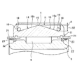
- FIG. 1 is a partial cross-sectional view showing a configuration of a rolling bearing device according to a first embodiment of the present invention.
- a rolling bearing device 1 is for supporting a drive roll of a continuous casting facility, and includes a rolling bearing 2 and a bearing box 10 having an arcuate cross section that accommodates the rolling bearing 2. Yes.
- the rolling bearing 2 is formed between an inner ring 3 in which the shaft portion of the drive roll is fitted on the inner peripheral side, an outer ring raceway 10 a formed in the bearing box 10, and an inner ring raceway 3 a formed on the outer peripheral surface of the inner ring 3.
- a plurality of cylindrical rollers 4 arranged to roll freely.
- the bearing box 10 is configured by combining an upper portion 11 and a lower portion 12 and is integrally fastened by a bolt or the like (not shown).
- the upper part 11 is arrange
- the lower side portion 12 is disposed on the side farther from the slab than the upper side portion 11 in the continuous casting facility, and is fixed to the continuous casting facility.
- the semicircular outer ring raceway 10a is formed on the inner peripheral side of the upper portion 11.
- An outer ring member (not shown) that forms an annular outer ring raceway by being combined with the semicircular outer ring raceway 10 a of the upper side part 11 is disposed on the inner peripheral side of the lower side portion 12.
- the outer peripheral surface of the outer ring member is formed as a spherical convex curved surface.
- the inner peripheral surface of the lower side part 12 is formed in the concave curved surface which follows the outer peripheral surface of the said outer ring member. For this reason, the outer peripheral surface of the outer ring member can slide with respect to the inner peripheral surface of the lower side portion 12 so as to swing the axis, and the outer ring member is aligned with respect to the lower side portion 12.
- the bearing housing 10 accommodates the rolling bearing 2 inside while having a function as an outer ring of the rolling bearing 2.
- a water cooling jacket 13 is provided on the upper portion 11 of the bearing box 10 facing the slab.
- the water cooling jacket 13 is for preventing heat radiated from the slab conveyed by the drive roll from being transmitted to the rolling bearing 2.
- the water cooling jacket 13 includes a recess 14 formed in the upper portion 11 and the recess 14.
- a lid 15 that forms a space R with the concave portion 14 by being closed is formed. The water cooling jacket 13 prevents the radiant heat from the slab from being transmitted to the rolling bearing 2 by introducing cooling water into the space R surrounded by the recess 14 and the lid 15.
- FIG. 2 is a sectional view taken along line II-II in FIG. 1
- FIG. 3 is a sectional view taken along line III-III in FIG. 1
- FIG. 4 is a sectional view taken along line IV-IV in FIG.
- a labyrinth ring 21 protruding outward in the axial direction is provided at both ends of the inner peripheral surface of the upper portion 11 (lower portion 12).
- the labyrinth ring 21 is inserted in a non-contact manner into an annular groove formed on an end face of each roll (not shown) that is axially opposed to both ends of the upper portion 11 (lower side portion 12).
- the labyrinth is made up of.
- a seal member 22 and a packing 23 for sealing between the two are disposed between the inner peripheral surface of the labyrinth ring 21 and the outer peripheral surface of the inner ring 3.
- the labyrinth ring 21, the seal member 22, and the packing 23 seal an annular gap between the bearing housing 10 and the inner ring 3.
- the recess 14 is formed to be recessed inward in the radial direction with respect to the outer peripheral surface of the upper portion 11, and includes a bottom 16 along the outer periphery of the rolling bearing 2, a shaft A circumferential wall 17 that is provided on both ends in the circumferential direction of the bottom 16 along the direction and surrounds both ends in the circumferential direction of the bottom 16, and an axis of the bottom 16 provided on both ends in the axial direction of the bottom 16 along the circumferential direction. It is comprised by the axial direction wall part 18 surrounding the direction both ends.
- the recess 14 is formed with a substantially uniform width dimension in the axial direction and the circumferential direction, and a pair of water supply ports 19 are formed on one end side in the circumferential direction.
- a pair of drain ports 20 are formed on the other end side in the circumferential direction.
- the arrangement in the axial direction of the pair of water supply ports 19 and the pair of drainage ports 20 is the same as that of the conventional water cooling jacket shown in FIG. Located in the corner.
- the pair of water supply ports 19 are connected to a water supply mechanism for supplying cooling water (not shown) via a water supply passage 19 a provided in the bearing box 10, respectively. Cooling water is introduced into the space R of the jacket 13.
- the pair of drainage ports 20 are connected to a drainage mechanism for draining cooling water (not shown) via drainage channels 20 a provided in the bearing box 10, respectively, and cooling in the space R of the water cooling jacket 13 is performed. Drain the water.
- the bottom portion 16 includes a first inclined surface 16a that is inclined radially inward from the axial center to one axial end, and a second inclined surface that is inclined radially inward from the axial central to the other axial end. 16b.
- Both the inclined surfaces 16a and 16b are formed in conical surfaces with the axis of the rolling bearing 2 as the central axis.
- Both the inclined surfaces 16 a and 16 b are formed by turning along an arc centered on the axis of the rolling bearing 2.
- Both the inclined surfaces 16a and 16b are formed with turning grooves of a groove extending in the circumferential direction with a depth of about 0.1 mm at an interval of about 5 mm in the axial direction.
- the bottom 16 is inclined first in the radial direction from the axial center to the one axial end, and the other axial end from the axial center.
- the cooling water introduced into the water cooling jacket 13 from the pair of water supply ports 19 on one end side in the circumferential direction is formed on both sides in the axial direction. While rectifying, the other end in the circumferential direction where the pair of drainage ports 20 are located can be reached. As a result, it is possible to suppress the cooling water from staying in the intermediate portion between the pair of drain ports 20 without increasing the amount of water supply, and to suppress the bubbles from staying in the intermediate portion.
- suppression of bubbles in the water cooling jacket 13 is suppressed without increasing the amount of water supply by a simple structure in which the bottom portion 16 is configured by the first and second inclined surfaces 16a and 16b. Since it can implement
- the bottom part 16 is the cooling which passes the inside of the water cooling jacket 13 in the circumferential direction. Water can be uniformly rectified with respect to the axial direction and the circumferential direction, and bubbles can be prevented from staying in the water cooling jacket 13 more effectively.
- FIG. 5 is a partial cross-sectional view showing the configuration of the rolling bearing device according to the second embodiment of the present invention
- FIG. 6 is VI-VI, which is substantially the center in the circumferential direction of the water cooling jacket 13 in FIG.
- FIG. 7 is a sectional view taken along line VII-VII, which is one end side in the circumferential direction of the water cooling jacket 13 in FIG. 5, and FIG. 8 is the other end side in the circumferential direction of the water cooling jacket 13,
- FIG. 7 is a sectional view taken along line VIII-VIII.
- 5 shows a cross section taken along line VV in FIG. 6, and FIGS. 6 to 8 show cross sections of the rolling bearing 2 in the axial direction.
- the first inclined surface 16 a has an axis of the bottom portion 16 with respect to one axial end portion of the bottom portion 16 in the axial section including the central axis of the rolling bearing 2 of the concave portion 14. Curved from the axial center of the bottom 16 toward one axial end so that the radial height of the rolling bearing 2 in the central direction gradually increases from the circumferential center of the bottom 16 toward both ends of the circumferential direction.
- the second inclined surface 16b is inclined, and the radial direction of the rolling bearing 2 in the axial center of the bottom portion 16 with respect to the other axial end portion of the bottom portion 16 in the axial section including the central axis of the rolling bearing 2 of the concave portion 14 is inclined.
- the upper peripheral surface of the bearing housing 10 of the present embodiment is centered on an axis Q located on the lower side (the far side from the slab) than the axis P of the inner ring 3 (the central axis of the rolling bearing 2).
- the inner and outer peripheral surfaces of the lid 15 are accordingly formed in an arc shape centered on the axis Q.
- the shaft center Q is below the shaft center P (the far side from the slab) in the diameter direction of the rolling bearing that connects the center of the bottom 16 in the circumferential direction and the shaft center P of the inner ring 3 (the center axis of the rolling bearing 2). To position.
- the center T in the axial direction is closest to the inner peripheral surface of the lid 15. Further, the center T in the axial direction of the bottom portion 16 is formed in a concentric arc shape (an arc shape centered on the point Q) having a smaller radius than the inner peripheral surface of the lid 15. Accordingly, as shown in FIGS. 6 to 8, the distance A between the inner peripheral surface of the lid 15 and the axial center T of the bottom portion has a substantially constant dimension in the water cooling jacket 13. Further, both end portions in the axial direction of the bottom portion 16 are formed in an arc shape centering on the axis P of the inner ring 3, and the radius thereof is the axial direction of the bottom portion 16 at the circumferential center as shown in FIG. The radial height between the center and both axial ends of the bottom portion 16 is set to be the dimension B1.
- the first inclined surface 16a has an arc shape when viewed from the circumferential direction, and the arc is an axial position from the axial center T of the bottom portion 16 to one end portion in the axial direction when the concave portion 14 is viewed in the axial direction. Accordingly, the center of the arc is gradually changed from the axis Q to the axis P, and the radius is gradually decreased accordingly, so that the axial direction center T of the bottom 16 is directed toward one end in the axis direction. It is formed so as to incline radially inward. That is, at the center T in the axial direction of the bottom portion 16, as shown in FIG.
- the arc of the intermediate portion between the axial center T and one axial end portion is proportional to the center of the arc between the axis P and the axis Q according to the position of the portion in the axial direction.
- the radius S3 is also set by changing proportionally according to the position of the portion in the axial direction.
- the first inclined surface 16a smoothly smooths the axial center T of the bottom portion 16 and one axial end portion of the bottom portion 16 forming an arc having a smaller radius than the arc of the axial center T of the bottom portion. It is curved and inclined so as to be connected, and the radial height dimension B2 (FIGS. 7 and 8) of the axial center T of the bottom portion 16 with respect to one axial end portion of the bottom portion 16 at both circumferential ends of the water cooling jacket 13 is It is higher than the radial height dimension B ⁇ b> 1 (FIG. 6) at the circumferential center of the water cooling jacket 13.
- the first inclined surface 16a is formed in the radial direction of the rolling bearing 2 in the axial center of the bottom portion 16 with respect to one axial end portion of the bottom portion 16 in the axial section including the central axis of the rolling bearing 2 of the concave portion 14.
- the height is formed so as to be curved and inclined radially inward from the axial center T of the bottom portion 16 toward one end portion in the axial direction so that the height gradually increases from the circumferential center of the bottom portion 16 toward both ends in the circumferential direction. ing.
- the second inclined surface 16b is also formed in the same manner as the first inclined surface 16a, and the axis of the bottom portion 16 with respect to the other axial end portion of the bottom portion 16 in the axial cross section including the central axis of the rolling bearing 2 of the concave portion 14. From the center in the axial direction T of the bottom portion 16 toward the other end in the axial direction, the radial height of the rolling bearing 2 at the center in the direction gradually increases from the circumferential center of the bottom portion 16 toward both ends in the circumferential direction. Thus, it is formed to be curved and inclined inward in the radial direction.
- the axial center T of the bottom portion 16 is formed in a concentric arc shape having a smaller radius than the inner peripheral surface with respect to the inner peripheral surface of the lid 15.
- the inclined surface 16a is formed in the axial direction of the bottom portion 16 so that the gap between the one axial end portion of the bottom portion 16 and the inner peripheral surface of the lid 15 gradually increases from the circumferential center of the bottom portion 16 toward both ends in the circumferential direction.
- the second inclined surface 16b is formed so as to be curved and inclined from the center T toward one end in the axial direction.
- the second inclined surface 16b has a gap between the other end in the axial direction of the bottom 16 and the inner peripheral surface of the lid 15 around the periphery of the bottom 16. It is formed so as to be curved and inclined from the axial center T of the bottom 16 toward the other axial end so as to gradually increase from the center in the direction toward both ends in the circumferential direction.
- first and second inclined surfaces 16a and 16b In order to form the first and second inclined surfaces 16a and 16b, an arc is formed in the circumferential direction with an arc center and a radius corresponding to the axial position at every predetermined pitch (for example, several millimeters) in the axial direction. Turn. For this reason, a large number of turning grooves along the circumferential direction having an axial pitch of several millimeters and a depth of about 0.1 millimeter are formed on both inclined surfaces 16a and 16b.
- the axial center T of the bottom portion 16 is closest to the inner peripheral surface of the lid 15 and has a substantially constant interval (A) in the circumferential direction.
- the introduced cooling water and the cooling water introduced to the second inclined surface 16b can be appropriately rectified so as not to be mixed excessively. As a result, the generation of bubbles can be more effectively prevented.
- the radial height of the rolling bearing 2 at the center in the axial direction of the bottom 16 relative to both ends in the axial direction of the bottom 16 is formed so as to gradually increase from the center in the circumferential direction of the bottom 16 toward both ends. Therefore, while making both inclined surfaces 16a and 16b suitable shape, the water supply port 19 and the water discharge port 20 can be ensured large, and cooling water can be smoothly supplied and discharged.
- 1st and 2nd inclined surface 16a, 16b was formed in the conical surface, 1st and 2nd inclined surface 16a, 16b is radial inside toward an axial direction one end part from an axial direction center.
- it may be a convex curved surface or a concave curved surface, and the inclination angle may be appropriately set according to the size of the water cooling jacket 13 or the like.
- the rolling bearing 1 was a cylindrical roller bearing was illustrated in the said embodiment, this invention is other ball bearings, such as an angular ball bearing, a cylindrical roller bearing, a tapered roller bearing, and a self-aligning roller bearing. It can also be applied to roller bearings such as.
- the first inclined surface whose bottom portion is inclined radially inward from the axial center to one axial end, and the radially inner side from the axial center to the other axial end.
- the pair of drainage ports are positioned while rectifying the cooling water introduced into the water-cooling jacket from the pair of water supply ports on one end side in the circumferential direction on both sides in the axial direction. The other end in the circumferential direction can be reached. As a result, it is possible to suppress the cooling water from staying in the intermediate portion between the pair of drain ports without increasing the amount of water supply, and to suppress the bubbles from staying in the intermediate portion.
- the present invention it is possible to suppress the retention of bubbles in the water cooling jacket without increasing the amount of water supply by a simple structure in which the bottom portion is configured by the first and second inclined surfaces. Thus, it is possible to suppress an increase in manufacturing cost and running cost of the rolling bearing device.
- the first and second inclined surfaces are conical surfaces having an axis of the rolling bearing as a central axis.
- the bottom portion can rectify the cooling water passing in the circumferential direction in the water cooling jacket uniformly with respect to the axial direction and the circumferential direction, and can more effectively suppress bubbles from staying. .
- the axial center of the bottom is formed in a concentric arc shape having a smaller radius than the inner peripheral surface with respect to the inner peripheral surface of the lid, and the first inclined surface is The radial height of the rolling bearing at the axial center of the bottom with respect to the axial one end of the bottom in the axial cross section including the central axis of the rolling bearing of the recess is circumferential from the circumferential center of the bottom.
- the second inclined surface includes the central axis of the rolling bearing, the second inclined surface being curved and inclined from the axial center to the one axial end so as to gradually increase toward both end sides.
- the radial height of the rolling bearing at the center in the axial direction of the bottom with respect to the other axial end of the bottom in the axial section is gradually increased from the circumferential center of the bottom toward both ends in the circumferential direction.
- the center in the axial direction of the bottom portion is closest to the inner peripheral surface of the lid and is at a substantially constant interval in the circumferential direction, so that the cooling water introduced into the first inclined surface and the second inclined surface
- the air can be appropriately rectified so as not to be excessively mixed with the cooling water introduced to the surface, and as a result, generation of bubbles can be more effectively prevented.
Landscapes
- Engineering & Computer Science (AREA)
- General Engineering & Computer Science (AREA)
- Mechanical Engineering (AREA)
- Mounting Of Bearings Or Others (AREA)
- Rolling Contact Bearings (AREA)
Abstract
Priority Applications (2)
| Application Number | Priority Date | Filing Date | Title |
|---|---|---|---|
| CN201080014390.8A CN102369368B (zh) | 2009-04-06 | 2010-04-02 | 滚动轴承装置 |
| US13/255,185 US8616778B2 (en) | 2009-04-06 | 2010-04-02 | Rolling bearing apparatus |
Applications Claiming Priority (4)
| Application Number | Priority Date | Filing Date | Title |
|---|---|---|---|
| JP2009-092270 | 2009-04-06 | ||
| JP2009092270 | 2009-04-06 | ||
| JP2010-064395 | 2010-03-19 | ||
| JP2010064395A JP5659521B2 (ja) | 2009-04-06 | 2010-03-19 | 転がり軸受装置 |
Publications (1)
| Publication Number | Publication Date |
|---|---|
| WO2010116954A1 true WO2010116954A1 (fr) | 2010-10-14 |
Family
ID=42936238
Family Applications (1)
| Application Number | Title | Priority Date | Filing Date |
|---|---|---|---|
| PCT/JP2010/056076 Ceased WO2010116954A1 (fr) | 2009-04-06 | 2010-04-02 | Dispositif de palier à roulement |
Country Status (4)
| Country | Link |
|---|---|
| US (1) | US8616778B2 (fr) |
| JP (1) | JP5659521B2 (fr) |
| CN (1) | CN102369368B (fr) |
| WO (1) | WO2010116954A1 (fr) |
Families Citing this family (10)
| Publication number | Priority date | Publication date | Assignee | Title |
|---|---|---|---|---|
| DE102014216313A1 (de) | 2014-08-18 | 2016-02-18 | Schaeffler Technologies AG & Co. KG | Lagerring und Verfahren zur Herstellung eines Lagerrings |
| US9388851B1 (en) * | 2014-12-22 | 2016-07-12 | Schaeffler Technologies AG & Co. KG | Split cylindrical roller bearing |
| DE102016224761A1 (de) | 2015-12-11 | 2017-06-14 | Sms Group Gmbh | Lagerbock zur Aufnahme eines Lagers für eine Rolle |
| US10422246B2 (en) * | 2016-10-24 | 2019-09-24 | General Electric Company | Bearing housing with impingement cooling system |
| DE102017203698A1 (de) * | 2017-03-07 | 2018-09-13 | Aktiebolaget Skf | Wälzlager und mechanisches System mit einem solchen Wälzlager |
| CN107327499B (zh) * | 2017-07-12 | 2019-07-26 | 安徽利达汽车轴承制造有限公司 | 一种方便冷却的带座轴承 |
| JP7311370B2 (ja) * | 2019-09-18 | 2023-07-19 | Jfeスチール株式会社 | 高温物体を搬送する回転ロールの軸受箱 |
| CN113550984A (zh) * | 2020-04-26 | 2021-10-26 | 斯凯孚公司 | 轴承座单元及其应用 |
| CN114754076A (zh) * | 2021-01-08 | 2022-07-15 | 斯凯孚公司 | 轴承座组件 |
| EP4159343A1 (fr) * | 2021-09-29 | 2023-04-05 | Primetals Technologies Austria GmbH | Palier support auxiliaire et installation de production dotée d'un tel palier support auxiliaire |
Citations (5)
| Publication number | Priority date | Publication date | Assignee | Title |
|---|---|---|---|---|
| JPS489855B1 (fr) * | 1969-10-13 | 1973-03-29 | ||
| JPS52106747U (fr) * | 1976-02-10 | 1977-08-13 | ||
| JPS6430925A (en) * | 1987-07-23 | 1989-02-01 | Koyo Seiko Co | Cooler for bearing device |
| JPH0160025U (fr) * | 1987-10-14 | 1989-04-17 | ||
| JP2001107977A (ja) * | 1999-10-13 | 2001-04-17 | Koyo Seiko Co Ltd | 軸受装置 |
Family Cites Families (10)
| Publication number | Priority date | Publication date | Assignee | Title |
|---|---|---|---|---|
| US4838041A (en) * | 1987-02-05 | 1989-06-13 | Gte Laboratories Incorporated | Expansion/evaporation cooling system for microelectronic devices |
| US5132780A (en) * | 1988-01-07 | 1992-07-21 | Prime Computer, Inc. | Heat sink apparatus with an air deflection member |
| US5019880A (en) * | 1988-01-07 | 1991-05-28 | Prime Computer, Inc. | Heat sink apparatus |
| US5155579A (en) * | 1991-02-05 | 1992-10-13 | Advanced Micro Devices | Molded heat sink for integrated circuit package |
| DE4114842C2 (de) * | 1991-05-07 | 1995-08-03 | Skf Gmbh | Mit einer Dichtungsanordnung versehenes Wälzlager |
| US5597034A (en) * | 1994-07-01 | 1997-01-28 | Digital Equipment Corporation | High performance fan heatsink assembly |
| US5915843A (en) * | 1996-07-12 | 1999-06-29 | The Torrington Company | Fluid-cooled bearing housing |
| CN1272153A (zh) * | 1998-05-28 | 2000-11-01 | 巴马格股份公司 | 引导、加热和输送长丝的导丝辊 |
| JP2006214646A (ja) * | 2005-02-03 | 2006-08-17 | Xenesys Inc | 熱交換用プレート |
| US7273090B2 (en) * | 2005-06-29 | 2007-09-25 | Intel Corporation | Systems for integrated cold plate and heat spreader |
-
2010
- 2010-03-19 JP JP2010064395A patent/JP5659521B2/ja not_active Expired - Fee Related
- 2010-04-02 WO PCT/JP2010/056076 patent/WO2010116954A1/fr not_active Ceased
- 2010-04-02 US US13/255,185 patent/US8616778B2/en not_active Expired - Fee Related
- 2010-04-02 CN CN201080014390.8A patent/CN102369368B/zh not_active Expired - Fee Related
Patent Citations (5)
| Publication number | Priority date | Publication date | Assignee | Title |
|---|---|---|---|---|
| JPS489855B1 (fr) * | 1969-10-13 | 1973-03-29 | ||
| JPS52106747U (fr) * | 1976-02-10 | 1977-08-13 | ||
| JPS6430925A (en) * | 1987-07-23 | 1989-02-01 | Koyo Seiko Co | Cooler for bearing device |
| JPH0160025U (fr) * | 1987-10-14 | 1989-04-17 | ||
| JP2001107977A (ja) * | 1999-10-13 | 2001-04-17 | Koyo Seiko Co Ltd | 軸受装置 |
Also Published As
| Publication number | Publication date |
|---|---|
| US20130129270A1 (en) | 2013-05-23 |
| JP2010261584A (ja) | 2010-11-18 |
| CN102369368A (zh) | 2012-03-07 |
| US8616778B2 (en) | 2013-12-31 |
| JP5659521B2 (ja) | 2015-01-28 |
| CN102369368B (zh) | 2014-12-03 |
Similar Documents
| Publication | Publication Date | Title |
|---|---|---|
| JP5659521B2 (ja) | 転がり軸受装置 | |
| US3628835A (en) | High-speed tapered roller bearing | |
| JP5816061B2 (ja) | 転がり軸受の潤滑装置 | |
| US6443623B2 (en) | Lubrication system for rolling bearing | |
| JP4848964B2 (ja) | 転がり軸受用保持器 | |
| JP6530381B2 (ja) | グリース潤滑式のアンギュラ玉軸受 | |
| JP2013015152A (ja) | 転がり軸受 | |
| US9958009B2 (en) | Roller bearing | |
| JP2004084799A (ja) | 円錐ころ軸受 | |
| JP2008240938A (ja) | 転がり軸受の潤滑装置 | |
| JP2000249153A (ja) | 圧延機用油膜軸受に用いるシールアセンブリ | |
| JP5500014B2 (ja) | 玉軸受用保持器および玉軸受 | |
| JP5321052B2 (ja) | 転がり軸受装置 | |
| EP1925832A1 (fr) | Palier à roulement, structure de support d essieu de moteur principal pour véhicule de chemin de fer, et structure de palier | |
| JP6589504B2 (ja) | ボールねじ | |
| JP2012255517A (ja) | 転がり軸受の潤滑装置 | |
| JP2008082496A (ja) | 転がり軸受の潤滑装置 | |
| JP2006022889A (ja) | 円筒ころ軸受 | |
| JP6878052B2 (ja) | シール付転がり軸受 | |
| KR200274613Y1 (ko) | 연속적인 주조 기계의 롤러에 대한 베어링 장치 | |
| JP5739293B2 (ja) | 転がり軸受装置 | |
| JP2007024258A (ja) | 転がり軸受の潤滑装置 | |
| JP6449065B2 (ja) | シール部材 | |
| JP5353432B2 (ja) | 転がり軸受装置 | |
| JP5840391B2 (ja) | 転がり軸受装置 |
Legal Events
| Date | Code | Title | Description |
|---|---|---|---|
| WWE | Wipo information: entry into national phase |
Ref document number: 201080014390.8 Country of ref document: CN |
|
| 121 | Ep: the epo has been informed by wipo that ep was designated in this application |
Ref document number: 10761653 Country of ref document: EP Kind code of ref document: A1 |
|
| WWE | Wipo information: entry into national phase |
Ref document number: 13255185 Country of ref document: US |
|
| NENP | Non-entry into the national phase |
Ref country code: DE |
|
| 122 | Ep: pct application non-entry in european phase |
Ref document number: 10761653 Country of ref document: EP Kind code of ref document: A1 |