WO2010137603A1 - Actionneur télécommandé - Google Patents
Actionneur télécommandé Download PDFInfo
- Publication number
- WO2010137603A1 WO2010137603A1 PCT/JP2010/058871 JP2010058871W WO2010137603A1 WO 2010137603 A1 WO2010137603 A1 WO 2010137603A1 JP 2010058871 W JP2010058871 W JP 2010058871W WO 2010137603 A1 WO2010137603 A1 WO 2010137603A1
- Authority
- WO
- WIPO (PCT)
- Prior art keywords
- pipe
- guide
- guide pipe
- posture
- spindle
- Prior art date
- Legal status (The legal status is an assumption and is not a legal conclusion. Google has not performed a legal analysis and makes no representation as to the accuracy of the status listed.)
- Ceased
Links
Images








Classifications
-
- A—HUMAN NECESSITIES
- A61—MEDICAL OR VETERINARY SCIENCE; HYGIENE
- A61B—DIAGNOSIS; SURGERY; IDENTIFICATION
- A61B17/00—Surgical instruments, devices or methods
- A61B17/16—Instruments for performing osteoclasis; Drills or chisels for bones; Trepans
- A61B17/1613—Component parts
- A61B17/1631—Special drive shafts, e.g. flexible shafts
-
- B—PERFORMING OPERATIONS; TRANSPORTING
- B23—MACHINE TOOLS; METAL-WORKING NOT OTHERWISE PROVIDED FOR
- B23B—TURNING; BORING
- B23B39/00—General-purpose boring or drilling machines or devices; Sets of boring and/or drilling machines
- B23B39/14—General-purpose boring or drilling machines or devices; Sets of boring and/or drilling machines with special provision to enable the machine or the drilling or boring head to be moved into any desired position, e.g. with respect to immovable work
-
- A—HUMAN NECESSITIES
- A61—MEDICAL OR VETERINARY SCIENCE; HYGIENE
- A61B—DIAGNOSIS; SURGERY; IDENTIFICATION
- A61B17/00—Surgical instruments, devices or methods
- A61B17/32—Surgical cutting instruments
- A61B17/320016—Endoscopic cutting instruments, e.g. arthroscopes, resectoscopes
- A61B17/32002—Endoscopic cutting instruments, e.g. arthroscopes, resectoscopes with continuously rotating, oscillating or reciprocating cutting instruments
-
- A—HUMAN NECESSITIES
- A61—MEDICAL OR VETERINARY SCIENCE; HYGIENE
- A61B—DIAGNOSIS; SURGERY; IDENTIFICATION
- A61B17/00—Surgical instruments, devices or methods
- A61B17/00234—Surgical instruments, devices or methods for minimally invasive surgery
- A61B2017/00292—Surgical instruments, devices or methods for minimally invasive surgery mounted on or guided by flexible, e.g. catheter-like, means
- A61B2017/003—Steerable
- A61B2017/00318—Steering mechanisms
- A61B2017/00323—Cables or rods
-
- A—HUMAN NECESSITIES
- A61—MEDICAL OR VETERINARY SCIENCE; HYGIENE
- A61B—DIAGNOSIS; SURGERY; IDENTIFICATION
- A61B17/00—Surgical instruments, devices or methods
- A61B17/00234—Surgical instruments, devices or methods for minimally invasive surgery
- A61B2017/00292—Surgical instruments, devices or methods for minimally invasive surgery mounted on or guided by flexible, e.g. catheter-like, means
- A61B2017/003—Steerable
- A61B2017/00318—Steering mechanisms
- A61B2017/00323—Cables or rods
- A61B2017/00327—Cables or rods with actuating members moving in opposite directions
Definitions
- the present invention relates to a remote operation type actuator that can change the posture of a tool by remote operation and is used for medical use, machining, and the like.
- the remote operation type actuator remotely controls a tool provided at the end of a long and narrow pipe portion having a linear shape or a curved shape.
- the conventional remote control actuator since the conventional remote control actuator only controls the rotation of the tool by remote control, in the case of medical use, it was difficult to process a complicated shape or a part that is difficult to see from the outside. Further, in drilling, it is required that not only a straight line but also a curved shape can be processed. Furthermore, in the cutting process, it is required that a deep part inside the groove can be processed.
- the prior art and problems of the remote control actuator will be described.
- an artificial joint insertion hole is formed in the medullary cavity at the center of the femur bone.
- a medical actuator used for such a bone cutting process a tool is rotatably provided at the distal end of an elongated pipe portion, and by driving a rotational drive source such as a motor provided on the proximal end side of the pipe portion,
- a rotational drive source such as a motor provided on the proximal end side of the pipe portion
- the adhesion time after the operation becomes longer, so the gap is as narrow as possible. desirable. It is also important that the contact surface between the living bone and the artificial joint is smooth, and high accuracy is required for processing the hole for inserting the artificial joint.
- the operating range of the tool is limited by the shape of the pipe part. It is difficult to process the artificial joint insertion hole so that the gap is narrow and the contact surface of both is smooth.
- the bones of patients undergoing artificial joint replacement are often weakened due to aging or the like, and the bones themselves may be deformed. Therefore, it is more difficult to process the artificial joint insertion hole than is normally conceivable.
- the present applicant tried to make it possible to change the posture of the tool by remote control for the purpose of relatively easily and accurately processing the hole for inserting the artificial joint. If the posture of the tool can be changed, the tool can be held in an appropriate posture regardless of the shape of the pipe portion, and fine machining can be performed.
- the tool is provided at the tip of the elongated pipe portion, there are many restrictions in providing a mechanism for changing the posture of the tool, and a device for overcoming it is necessary.
- some medical actuators that do not have an elongated pipe part can change the position of the part where the tool is provided relative to the hand-held part (for example, Patent Document 4), but the position of the tool can be changed remotely. None has been proposed to make it happen.
- the rotating shaft that transmits the rotation to the tool must be rotated at high speed.
- the mechanism for changing the posture of the tool is also provided in the elongated pipe portion provided with the rotation shaft, the structure becomes complicated. Therefore, it is required that the rotary shaft is accommodated functionally and compactly in the pipe portion, and the assembly and mass productivity of the pipe portion are good.
- the present invention provides a remote operation type actuator capable of changing the posture of a tool provided at the tip of a long and narrow pipe portion by remote operation and positioning the tip of the tool with high accuracy and having high machining accuracy. It is an object. Another object of the present invention is that the rotating shaft can be supported without difficulty in the pipe portion, the tool can be rotated at high speed for cutting, and the rotating shaft that transmits the rotation to the tool functions in the pipe portion. It is an object of the present invention to provide a remote control type actuator that is housed in a compact and compact manner and has good assembly and mass productivity of pipe parts.
- a remote-control actuator includes an elongated spindle guide portion, a tip member attached to the tip of the spindle guide portion via a tip member connecting portion so that the posture can be freely changed, and a base end of the spindle guide portion And the tip member rotatably supports a spindle holding a tool, and the spindle guide portion rotates a tool rotation drive source provided in the drive unit housing.
- a rotation shaft that transmits the tip member to the spindle, and a guide hole that penetrates both ends of the shaft, and a posture operation member that changes the posture of the tip member by advancing and retracting with the tip contacting the tip member.
- An attitude change drive source is provided in the drive housing to pass through the interior of the drive section and move the attitude operation member forward and backward.
- a guide pipe suppressing means that has an outer pipe that is an outer shell of the outer pipe portion and a guide pipe that is inside the outer pipe and has an inner diameter hole serving as the guide hole, and that suppresses the movement of the guide pipe within the outer pipe. It is provided.
- the bone or the like is cut by the rotation of the tool provided on the tip member.
- the tip of the posture operation member acts on the tip member, so that the posture can be changed to the tip of the spindle guide portion via the tip member connecting portion.
- the position of the tip member attached to is changed.
- the posture changing drive source is provided in the drive portion housing on the proximal end side of the spindle guide portion, and the posture change of the tip member is performed by remote control. Since the posture operation member is inserted into the guide hole, the posture operation member does not shift in the direction intersecting the longitudinal direction, and can always act properly on the tip member, and the posture change operation of the tip member Is done accurately.
- the rigidity of the guide pipe is increased by providing the guide pipe suppressing means for suppressing the movement of the guide pipe in the outer pipe. Accordingly, the displacement or force of the posture changing drive source provided in the drive unit housing can be accurately transmitted to the tip member, and the positioning accuracy of the tool is improved.
- the displacement or force escapes in the radial direction of the guide pipe in the process in which the displacement or force of the posture changing drive source is transmitted to the tip member via the posture operation member in the guide pipe. . For this reason, the displacement or force of the posture changing drive source is not accurately transmitted to the tip member, and the positioning accuracy of the tool is deteriorated.
- the positioning accuracy of the tool is improved.
- the guide pipe suppressing means may be means for pressing the guide pipe against the inner diameter surface of the outer pipe.
- the guide pipe suppressing means has an inner diameter dimension of the outer pipe, an outer diameter dimension of the guide pipe, and an outer diameter dimension of the rotary shaft support member.
- the guide pipe may be pressed against the inner diameter surface of the outer pipe by adjusting at least one or more.
- the guide pipe can be pressed against the inner diameter surface of the outer pipe by adjusting at least one of the dimensions of the respective parts. Since this configuration does not require high dimensional accuracy of each component, it can be manufactured at low cost.
- the rotation shaft is located in the center of the outer pipe, and a plurality of the guide pipes or at least one guide pipe and the outer diameter are provided between the rotation shaft and the inner diameter surface of the outer pipe.
- the same outer diameter member an arbitrary number of members that are the same as the guide pipe (hereinafter referred to as “the same outer diameter member”) are provided side by side in the circumferential direction, the inner diameter dimension of the outer pipe is D1, the guide pipe, and the outer pipe
- the outer diameter dimension of the diameter member is D2
- the outer diameter dimension of the rotating shaft support member is D3
- this invention has a plurality of rotating shaft support members which rotatably support the rotating shaft, and the guide pipe restraining means is provided between at least one pair of the adjacent rotating shaft support members,
- the guide pipe contact member which contacts may be sufficient.
- the guide pipe contact member may have an action of pressing the guide pipe against the inner diameter surface of the outer pipe.
- the rotary shaft support member is a rolling bearing, and when a spring element that applies preload to the rolling bearings is provided between adjacent rolling bearings, the guide pipe contact member is disposed on the inner ring side of the rolling bearing. It is good to provide in the axial direction location currently made.
- a spring element is provided between adjacent rolling bearings, interference between the spring element and the guide pipe contact member is achieved by providing a guide pipe contact member at an axial position where the spring element is disposed on the inner ring side of the rolling bearing. Can be avoided.
- the guide pipe suppressing means comprises
- the gap adjusting member for adjusting the gap dimension between the rotating shaft support member and the fixed support member may be used.
- the rotation shaft support member that rotatably supports the rotation shaft in the spindle guide portion, it is possible to rotate the rotation shaft at a high speed and transmit the rotation of the tool rotation drive source to the spindle. It is. Therefore, it can process by rotating a tool at high speed, and a to-be-cut surface can be finished finely. Since the rotation shaft support member is supported in a fixed state by the fixed support member, vibration of the rotation shaft can be suppressed, and damage to the rotation shaft and the rotation shaft support member can be prevented. In addition, since vibration of the entire actuator during use is reduced, operability is improved and noise can be reduced.
- the gap adjusting member for adjusting the gap dimension between the rotating shaft support member and the fixed support member is provided, it is possible to cope with the difference in the gap size due to processing accuracy and the like. Can be reliably supported in a fixed state.
- the rotary shaft support member can be reliably supported in a fixed state by the fixed support member, and the assembly and mass productivity are excellent. For example, when the gap adjusting member is not provided and the spindle guide portion is linear, if the gap between the rotating shaft supporting member and the fixed supporting member is too wide, the rotating shaft supporting member is firmly supported by the fixed supporting member. Cannot be performed, and the vibration of the rotating shaft increases.
- the rotating shaft and the rotating shaft support member may be damaged, and vibration and noise during use may increase.
- the spindle guide portion is curved, the assemblability deteriorates if the gap is narrow. If the gap adjustment member is provided, such a problem is solved.
- the gap adjusting member can be an elastic member provided on the outer periphery of the rotating shaft support member. If the gap adjusting member is an elastic member, the elastic member is deformed according to the size of the gap between the rotary shaft support member and the fixed support member, so that the rotary shaft support member can always be stably supported. Further, if the gap adjusting member is an elastic member, the vibration of the rotating shaft can be reduced by the vibration of the rotating shaft being absorbed by the elastic member.
- the rotating shaft support member is a rolling bearing in which one or more annular grooves are provided on the outer diameter surface of the outer ring, and the elastic member is fitted into the annular groove.
- O-rings can be used.
- the elastic member is an O-ring, the elastic member can be easily provided on the outer periphery of the rolling bearing, and assemblability is improved.
- the elastic member as the gap adjusting member may be a coating on the outer peripheral surface of the rotating shaft support member. If the elastic member is coated on the outer peripheral surface of the rotary shaft support member, the elastic member can be easily provided on the outer periphery of the rotary shaft support member, and the assemblability is improved.
- the gap size is preferably in the range of plus 100 ⁇ m to minus 10 ⁇ m. In general, if the gap dimension is too large, the vibration of the rotating shaft increases. For this reason, it is desirable that the gap dimension is as small as possible. However, when the spindle guide portion has a curved shape, the assemblability deteriorates unless there is a certain gap dimension. When the spindle guide portion has a linear shape or a shape close to a straight line, the gap can be a negative gap. If the negative gap is used, the rotary shaft support member is firmly fixed, but the assemblability of the extreme negative gap is impaired. From experiments and the like, it was found that the gap size is preferably within the above range.
- At least one end of the guide pipe is fixed to the outer pipe or a member fixed to the outer pipe.
- the end of the guide pipe can be fixed by any one of screws, press-fitting, bonding, and welding.
- a compressive force applying means for applying an axial compressive force to the guide pipe. If the compressive force applying means is provided, the guide pipe is deformed so as to eliminate the gap with the outer pipe, thereby suppressing the movement of the guide pipe. Further, since force is applied to the guide pipe from both ends, movement of the guide pipe in the axial direction is suppressed.
- the spindle guide portion may have a curved portion. Since the posture operation member is flexible, even if there is a curved portion in the spindle guide portion, it can be advanced and retracted in the guide hole.
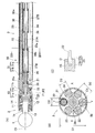
- (A) is a sectional view of the tip member and spindle guide portion of the remote control type actuator according to the first embodiment of the present invention
- (B) is a sectional view taken along the line IIB-IIB
- (C) is a sectional view of the tip member and the rotating shaft. It is a figure which shows a connection structure.
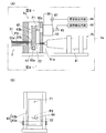
- (A) is a cross-sectional view of a tool rotation drive mechanism and a posture change drive mechanism of the remote operation type actuator
- (B) is a IIIB-IIIB cross-sectional view thereof.
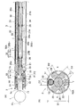
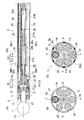
- (A) is a sectional view of a tip member and a spindle guide portion of a remote control type actuator according to a second embodiment of the present invention
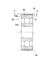
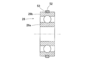
- (B) is a sectional view of the IVB-IVB. It is sectional drawing of the rotating shaft support member and guide pipe suppression means of the remote control type actuator. It is sectional drawing of the rotating shaft support member and guide pipe suppression means concerning a 1st modification. It is sectional drawing of the rotating shaft support member and guide pipe suppression means concerning a 2nd modification.
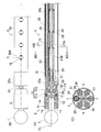
- (A) is a sectional view of a tip member and a spindle guide portion of a remote control type actuator according to a third embodiment of the present invention
- (B) is a VIIIB-VIIIB
- (C) is a VIIIC-VIIIC sectional view.
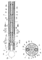
- (A) is a sectional view of a tip member and a spindle guide portion of a remote control type actuator according to a fourth embodiment of the present invention, (B) is its IXB-IXB, and (C) is its IXC-IXC sectional view.
- (A) is a sectional view of a tip member and a spindle guide portion of a remote control type actuator according to a fifth embodiment of the present invention
- (B) is a sectional view of the XIB-XIB.
- (A) is a sectional view of a tip member and a spindle guide part of a remote control type actuator according to a sixth embodiment of the present invention
- (B) is a plan view thereof
- (C) is a sectional view of XIC-XIC.
- (A) is a sectional view of a tip member and a spindle guide portion of a remote control type actuator according to a seventh embodiment of the present invention
- (B) is a plan view thereof
- (C) is a sectional view thereof taken along XIIC-XIIC.
- (A) is a sectional view of a tip member and a spindle guide portion of a remote control type actuator according to an eighth embodiment of the present invention
- (B) is a sectional view taken along line XIIIB-XIIIB.
- (A) is a sectional view of a tip member and a spindle guide portion of a remote control type actuator according to a ninth embodiment of the present invention
- (B) is a sectional view of XIVB-XIVB.
- (A) is a cross-sectional view of a tool rotation drive mechanism and a posture change drive mechanism of the remote operation type actuator
- (B) is a cross-sectional view of the XVB-XVB.
- (A) is a sectional view of a tip member and a spindle guide portion of a remote control type actuator according to a tenth embodiment of the present invention
- (B) is a sectional view of the XVIB-XVIB.
- (A) is a sectional view of a distal end member and a spindle guide portion of a remote control type actuator according to an eleventh embodiment of the present invention
- (B) is a sectional view of XVIIB-XVIIB
- (C) is a proximal end of a housing of the distal end member. It is the figure seen from the side.
- (A) is a sectional view of a tip member and a spindle guide portion of a remote control type actuator according to a twelfth embodiment of the present invention
- (B) is a sectional view of the XVIIIB-XVIIIB
- (C) is a sectional view of the tip member and a rotating shaft. It is a figure which shows a connection structure. It is sectional drawing of the spindle guide part of the remote control type actuator concerning 13th Embodiment of this invention.
- FIG. 1 (A) shows a remote control type actuator in which the spindle guide part 3 has a linear shape
- FIG. 1 (B) shows a remote control type actuator in which the spindle guide part 3 has a curved shape.
- this remote control type actuator includes a tip member 2 that holds a rotary tool 1, an elongated spindle guide portion 3 that is attached to the tip of the tip member 2 so that its posture can be freely changed, A drive unit housing 4a to which the base end of the spindle guide unit 3 is coupled, and a controller 5 for controlling the tool rotation drive mechanism 4b and the attitude change drive mechanism 4c in the drive unit housing 4a are provided.
- the drive unit housing 4a constitutes the drive unit 4 together with the built-in tool rotation drive mechanism 4b and posture changing drive mechanism 4c.
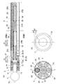
- FIG. 2 (A) is a cross-sectional view of the tip member 2 and the spindle guide portion 3 of the remote control type actuator shown in FIG. 1 (A).
- a spindle 13 is rotatably supported by a pair of bearings 12 inside a substantially cylindrical housing 11.
- the spindle 13 has a cylindrical shape with an open end, and the shank 1a of the tool 1 is inserted into the hollow portion in a fitted state, and the shank 1a is non-rotatably coupled by the rotation prevention pin 14.
- the tip member 2 is attached to the tip of the spindle guide portion 3 via the tip member connecting portion 15.
- the tip member connecting portion 15 is a means for supporting the tip member 2 so that the posture thereof can be freely changed, and includes a spherical bearing.
- the distal end member connecting portion 15 includes a guided portion 11 a that is a reduced inner diameter portion of the proximal end of the housing 11 and a hook-shaped portion of a retaining member 21 that is fixed to the distal end of the spindle guide portion 3. It is comprised with the guide part 21a.
- the guide surfaces F1 and F2 that are in contact with each other 11a and 21a are spherical surfaces having a center of curvature O located on the center line CL of the spindle 13 and having a smaller diameter toward the proximal end side.
- the spindle guide portion 3 has a rotating shaft 22 that transmits the rotational force of the tool rotation drive source 41 (FIG. 3A) in the drive portion housing 4a to the spindle 13.
- the rotating shaft 22 is a wire and can be elastically deformed to some extent.
- the material of the wire for example, metal, resin, glass fiber or the like is used.
- the wire may be a single wire or a stranded wire.
- the spindle 13 and the rotary shaft 22 are connected so as to be able to transmit rotation via a joint 23 such as a universal joint.
- the joint 23 includes a groove 13 a provided at the closed base end of the spindle 13 and a protrusion 22 a provided at the distal end of the rotating shaft 22 and engaged with the groove 13 a.
- the center of the connecting portion between the groove 13a and the protrusion 22a is at the same position as the center of curvature O of the guide surfaces F1 and F2.
- the rotating shaft 22 and the protrusion 22a may be configured as separate members.
- the spindle guide part 3 has an outer pipe 25 that is an outer part of the spindle guide part 3, and the rotating shaft 22 is located at the center of the outer pipe 25.
- the rotary shaft 22 is rotatably supported by rolling bearings 26 serving as a plurality of rotary shaft support means that are arranged apart from each other in the axial direction.
- spring elements 27A and 27B for generating a preload on the rolling bearing 26 are provided.
- the spring elements 27A and 27B are, for example, compression coil springs.
- the retaining member 21 is fixed to the pipe end portion 25a of the outer pipe 25 by a fixing pin 28, and rotatably supports the distal end portion of the rotary shaft 22 via a rolling bearing 29 at the distal end inner peripheral portion thereof.
- the pipe end portion 25a may be a separate member from the outer pipe 25 and may be joined by welding or the like.
- one guide pipe 30 penetrating at both ends is provided. Inside the guide hole 30 a which is the inner diameter hole of the guide pipe 30, the wire 31 a and the both ends thereof are provided.
- a posture operation member 31 composed of a columnar pin 31b is inserted in such a manner as to be able to advance and retreat.
- the distal end of the columnar pin 31b on the distal end member 2 side is spherical, and is in contact with the proximal end surface 11b of the housing 11 which is a contact surface with the posture operation member 31 of the distal end member 2.
- the base end surface 11b of the housing 11 is an inclined surface that is closer to the spindle guide portion 3 side toward the outer diameter side.
- the tip of the columnar pin 31b on the drive unit housing 4a side is also spherical, and is in contact with a side surface of a lever 43b (FIG. 3A) described later.
- the columnar pin 31b may be omitted, and the posture operation member 31 may be configured with only one wire 31a.
- compression is provided between the proximal end surface of the housing 11 of the distal end member 2 and the distal end surface of the outer pipe 25 of the spindle guide portion 3 at a position 180 degrees relative to the circumferential position where the posture operation member 31 is located.
- a restoring elastic member 32 made of a coil spring is provided. The restoring elastic member 32 acts to urge the tip member 2 toward a predetermined posture.
- a plurality of pieces are provided on the same pitch circle C1 as the guide pipe 30 separately from the guide pipe 30.
- a reinforcing shaft 34 is arranged. These reinforcing shafts 34 are for ensuring the rigidity of the spindle guide portion 3.
- the reinforcing shaft 34 is a member whose outer diameter is the same as that of the guide pipe 30. The intervals between the guide pipe 30 and the reinforcing shaft 34 are equal.
- the outer diameter of the outer pipe 25 is D1
- the outer diameter of the guide pipe 30 and the reinforcing shaft 34 is D2
- the outer diameter of the rolling bearing 26 is D3
- the relation of D1 / 2 ⁇ D2 + D3 / 2 is established.
- the dimensions are set. That is, there is no gap or a negative gap between the outer pipe 25 and the guide pipe 30 and the reinforcing shaft 34 and between the guide pipe 30 and the reinforcing shaft 34 and the rolling bearing 26.
- the guide pipe 30 and the reinforcing shaft 34 are pressed against the inner diameter surface of the outer pipe 25 and are pressed against the outer diameter surface of the rolling bearing 26. Therefore, the guide pipe 30 and the reinforcing shaft 34 are suppressed from moving in the radial direction of the outer pipe 25 within the outer pipe 25. Further, the guide pipe 30 and the reinforcing shaft 34 are also difficult to move due to friction between the guide pipe 30 and the reinforcing shaft 34 and the contact surfaces of the outer pipe 25 and the rolling bearing 26. That is, in this embodiment, the outer pipe 25 and the rolling bearing 26 constitute the guide pipe suppressing means 50 that suppresses the movement of the guide pipe 30 in the outer pipe 25.
- the relationship is established by adjusting at least one of the inner diameter D1 of the outer pipe 25, the outer diameter D2 of the guide pipe 30 and the reinforcing shaft 34, and the outer diameter D3 of the rolling bearing 26.
- a plurality of types of guide pipes 30 and reinforcing shafts 34 having different outer diameters D2 are prepared, and suitable ones are selectively used.
- a plurality of rolling bearings 26 having different outer diameter dimensions D3 may be prepared, or a plurality of outer pipes 25 having different inner diameter dimensions D1 may be prepared. According to this method, since the dimensional accuracy of each component 25, 26, 30, 34 is not required to be high, the spindle guide portion 3 can be manufactured at a low cost.
- the spindle guide portion 3 when the spindle guide portion 3 is a curved remote control type actuator, the outer pipe 25, the guide pipe 30, and the reinforcing shaft 34 need to be curved, although illustration is omitted.
- the rotary shaft 22 is preferably made of a material that is easily deformed, and for example, a shape memory alloy is suitable.
- the spindle guide portion 3 has the same configuration as that of a linear shape.
- FIG. 3A shows the tool rotation drive mechanism 4b and the posture change drive mechanism 4c in the drive unit housing 4a.
- the tool rotation drive mechanism 4 b includes a tool rotation drive source 41.
- the tool rotation drive source 41 is, for example, an electric motor, and its output shaft 41 a is coupled to the proximal end of the rotation shaft 22.
- the rotating shaft 22 passes through an opening 44 formed in the lever 43b described later.
- the posture changing drive mechanism 4 c includes a posture changing drive source 42 corresponding to the posture operating member 31.
- the posture changing drive source 42 is, for example, an electric linear actuator, and the movement of the output rod 42 a that moves in the left-right direction in FIG. 3A is transmitted to the posture operating member 31 through the force transmission mechanism 43.
- the boost transmission mechanism 43 has a lever 43b that is rotatable around a support shaft 43a.
- the force of the output rod 42a acts on an action point P1 of the lever 43b that is long from the support shaft 43a.
- the force is applied to the posture operation member 31 at the force point P ⁇ b> 2 having a short distance, and the output of the posture changing drive source 42 is increased and transmitted to the posture operation member 31.
- the posture changing drive source 42 may be a rotary motor. Further, instead of providing a linear actuator or the like, the posture of the tip member 2 may be remotely operated manually.
- the posture changing drive mechanism 4c is provided with a movement amount detector 45 for individually detecting the movement amount of each posture changing drive source 42.
- the detection value of the movement amount detector 45 is output to the posture detection means 46.
- the attitude detection means 46 detects the tilt attitude of the tip member 2 around the X axis (FIG. 2B) based on the output of the operation amount detector 45.
- the posture detection means 46 has relationship setting means (not shown) in which the relationship between the tilt posture and the output signal of the motion amount detector 45 is set by an arithmetic expression or a table, and the relationship is determined from the input output signal.
- the tilting posture is detected using setting means.
- the posture detection means 46 may be provided in the controller 5 (FIG. 1A) or may be provided in an external control device.
- the posture changing drive mechanism 4c is provided with a wattmeter 47 for individually detecting the amount of power supplied to the posture changing drive source 42, which is an electric actuator.
- the detected value of the supplied wattmeter 47 is output to the load detecting means 48.
- the load detection means 48 detects the load acting on the tip member 2 based on the output of the wattmeter 47.
- the load detection means 48 has relation setting means (not shown) in which the relation between the load and the output signal of the supplied wattmeter 47 is set by an arithmetic expression or a table, and the relation setting means is determined from the input output signal.
- the load is detected using.
- the load detecting means 48 may be provided in the controller 5 (FIG. 1A) or may be provided in an external control device.
- the controller 5 controls the tool rotation drive source 41 and the posture change drive source 42 based on the detected values of the posture detection means 46 and the load detection means 48.
- this remote control type actuator When the tool rotation drive source 41 in FIG. 3A is driven, the rotational force is transmitted to the spindle 13 in FIG. 2A through the rotation shaft 22, and the tool 1 rotates together with the spindle 13.
- the load acting on the tip member 2 when the tool 1 is rotated to cut bone or the like is detected by the load detection means 48 from the detection value of the wattmeter 47 shown in FIG. In accordance with the load value detected in this way, the load acting on the tip member 2 is properly maintained by controlling the feed amount of the entire remote control type actuator and the posture change of the tip member 2 to be described later. Can cut bone.
- the posture changing drive source 42 is driven to change the posture of the tip member 2 by remote control.
- the posture operation member 31 in FIG. 2A is advanced to the distal end side by the posture change drive source 42
- the housing 11 of the distal member 2 is pushed by the posture operation member 31, and the distal member 2 is moved to the position shown in FIG. In A)
- the posture is changed along the guide surfaces F1 and F2 to the side where the front end side is directed downward.
- the posture operation member 31 is retracted by the posture changing drive source 42
- the housing 11 of the tip member 2 is pushed back by the elastic repulsive force of the restoring elastic member 32, and the tip member 2 is shown in FIG.
- the posture is changed along the guide surfaces F1 and F2 to the side facing upward.
- the pressure of the posture operation member 31, the elastic repulsive force of the restoring elastic member 32, and the reaction force from the retaining member 21 act on the tip member connecting portion 15, and the balance of these acting forces
- the posture of the tip member 2 is determined.
- the posture of the tip member 2 is detected by the posture detection means 46 from the detection value of the movement amount detector 45 (FIG. 3A). Therefore, the posture of the tip member 2 can be appropriately controlled by remote operation.
- proximal end surface 11b of the housing 11 of the distal end member 2 is an inclined surface closer to the spindle guide portion 3 side toward the outer diameter side, when the attitude operating member 31 pushes the proximal end surface 11b of the housing 11, the attitude operating member The base end surface 11b of the housing 11 is slippery with respect to 31 and the housing 11 can be smoothly changed in posture.
- the posture operation member 31 Since the posture operation member 31 is inserted through the guide hole 30a of the guide pipe 30, the posture operation member 31 does not shift in the direction intersecting the longitudinal direction and can always act properly on the tip member 2. Thus, the posture changing operation of the tip member 2 is accurately performed. Further, since the posture operation member 31 is made of a wire and is flexible, the posture changing operation of the tip member 2 is reliably performed even if the spindle guide portion 3 is curved. Furthermore, since the center of the connecting portion between the spindle 13 and the rotating shaft 22 is at the same position as the center of curvature O of the guide surfaces F1 and F2, a force for pushing and pulling against the rotating shaft 22 by changing the posture of the tip member 2 is increased. Accordingly, the posture of the tip member 2 can be changed smoothly.
- the guide pipe restraining means 50 for restraining the guide pipe 30 from moving in the outer pipe 25 is provided, the rigidity of the guide pipe 30 is kept high. Thereby, the displacement or force of the attitude changing drive source 42 provided in the drive unit housing 4a can be accurately transmitted to the tip member 2, and the positioning accuracy of the tool 1 is good.
- the displacement or force of the posture changing drive source 42 is transmitted to the tip member 2 via the posture operation member 31 in the guide pipe 30 in the course of the displacement or force. Since the pipe 30 escapes in the radial direction, the displacement or force of the posture changing drive source 42 is not accurately transmitted to the tip member 2, and the positioning accuracy of the tool 1 is deteriorated.
- the rotary shaft 22 is rotatably supported by a rolling bearing 26 that is a rotary shaft support member. Therefore, the rotary shaft 22 is rotated at a high speed so that the rotation of the tool rotation drive source 41 is applied to the spindle 13. It is possible to communicate. Since the preload is applied to the rolling bearing 26 by the spring elements 27A and 27B, the supporting rigidity of the rolling bearing 26 is high and suitable for rotating the rotating shaft 22 at high speed. Since the spring elements 27A and 27B are provided between the adjacent rolling bearings 26, the spring elements 27A and 27B can be provided without increasing the diameter of the spindle guide portion 3. Thus, since the rotating shaft 22 can be rotated at a high speed, the tool 1 can be processed at a high speed. Therefore, the surface to be cut can be finished cleanly, and the cutting resistance acting on the tool 1 can be reduced.
- the elongated spindle guide portion 3 needs to be provided with the rotating shaft 22 and the posture operation member 31 in a protected state.
- the rotating shaft 22 is provided at the center of the outer pipe 25.
- This remote-operated actuator is used, for example, to cut the medullary cavity of bone in artificial joint replacement surgery.
- all or part of the tip member 2 shown in FIG. Used by inserting into the body. For this reason, if the posture of the tip member 2 can be changed by remote control as described above, the bone can be processed while the tool 1 is always held in an appropriate posture, and the artificial joint insertion hole is finished with high accuracy. Can do.
- the spindle guide part 3 has a curved shape, it may be possible to insert the tip member 2 to the back of a bone that is difficult to reach with a linear shape.
- the spindle guide portion 3 shown in FIGS. 1 (A) and 1 (B) can be used in a precise manner when machining a prosthetic joint insertion hole in a prosthetic joint replacement surgery by properly using a linear guide and a curved spindle guide 3 respectively. it can.
- the guide pipe suppressing means 50A in this embodiment has a different configuration from the guide pipe suppressing means 50 of the first embodiment described above. That is, as shown in FIG. 5, there is a gap 51 between the guide pipe 30 and the reinforcing shaft 34 and the rolling bearing 26, and an annular surface is formed on the outer diameter surface of the outer ring 26 b of the rolling bearing 26 so as to fill the gap 51.
- An elastic member 52 is provided.
- the elastic member 52 has a wide band shape and covers the entire axial direction of the outer diameter surface of the outer ring 26b.
- the material of the elastic member 52 is preferably a material having a low hardness. For example, a rubber material such as silicon rubber or a resin material such as fluororesin is used.
- the inner diameter D1 of the outer pipe 25, the outer diameter D2 of the guide pipe 30 and the reinforcing shaft 34 as the same outer diameter member which is the same member as the outer diameter.
- the dimensions are set so that D1 / 2 ⁇ D2 + D3 / 2. That is, there is no gap between the outer pipe 25 and the guide pipe 30 and the reinforcing shaft 34, and between the guide pipe 30 and the reinforcing shaft 34 and the rolling bearing 26, or a regular gap. Then, the thickness T of the elastic member 52 when no external force is applied is made larger than the gap dimension ⁇ .
- the elastic member 52 When the elastic member 52 is provided, the elastic member 52 is elastically deformed according to the gap 51, whereby the guide pipe 30 and the reinforcing shaft 34 are pressed against the inner diameter surface of the outer pipe 25. Therefore, the guide pipe 30 and the reinforcing shaft 34 are restrained from moving in the radial direction of the outer pipe 25 within the outer pipe 25. Further, the guide pipe 30 and the reinforcing shaft 34 are hardly moved by friction between the contact surfaces of the guide pipe 30 and the reinforcing shaft 34 and the outer pipe 25. That is, in this embodiment, the outer pipe 25, the rolling bearing 26, and the elastic member 52 constitute guide pipe suppressing means 50 ⁇ / b> A that suppresses the movement of the guide pipe 30 in the outer pipe 25.
- FIG. 6 shows a first modification of the elastic member as the guide pipe suppressing means.
- the elastic member 52 has a narrow band shape and is fitted in an annular groove 53 provided on the outer diameter surface of the outer ring 26 b of the rolling bearing 26. By fitting the elastic member 52 into the annular groove 53, it is possible to prevent the elastic member 52 from being detached from the outer diameter surface of the outer ring 26b.
- FIG. 7 shows a second modification of the elastic member.
- the elastic member 52 includes two O-rings 52a, and each O-ring 52a is fitted into an annular groove 53 provided on the outer diameter surface of the outer ring 26b of the rolling bearing 26. If the elastic member 52 is composed of the O-ring 52a, the elastic member 52 can be easily provided on the outer diameter surface of the outer ring 26b, and the assemblability is good.
- the elastic member 52 since the elastic member 52 is composed of two O-rings 52a, the rolling bearing 26 can be stably fixed, and even if a moment load is applied to the rolling bearing 26, it is supported at two points. Therefore, the moment load or the like acting on the rolling bearing 26 due to the deformation of the O-ring 52a can be reduced without extremely reducing the support rigidity.
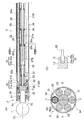
- the guide pipe suppression means 50B in this embodiment has a different configuration from the guide pipe suppression means 50 of the first embodiment described above. That is, as shown in FIG. 8A, the guide pipe restraining means 50B is provided with a guide pipe contact member 55 in contact with the guide pipe 30 and the reinforcing shaft 34 in a part between the adjacent rolling bearings 26. is there.
- the guide pipe contact member 55 has a shape that makes contact with the inner diameter side surfaces of the guide pipe 30 and the reinforcing shaft 34 with respect to the outer pipe 25.
- the axial position where the guide pipe contact member 55 is provided is the axial position where the inner ring spring element 27A is disposed, and the inner diameter of the guide pipe contact member 55 is larger than the outer diameter of the inner ring spring element 27A. It is enlarged. Thereby, interference with spring element 27A, 27B and the guide pipe contact member 55 can be avoided.
- one and five guide pipes 30 and reinforcing shafts 34 are respectively arranged as in the first embodiment.
- the guide pipe 30 and the reinforcing shaft 34 can be pressed against the inner diameter surface of the outer pipe 25.
- the diameter of a circle C2 connecting the bottoms of the recesses 55a into which the guide pipe 30 and the reinforcing shaft 34 are fitted in the guide pipe contact member 55 is D4
- the dimensions are set so that D1 / 2 ⁇ D2 + D4 / 2.
- the guide pipe suppressing means 50C in this embodiment has a different configuration from the guide pipe suppressing means 50 of the first embodiment described above. That is, as shown in FIG. 9A, the guide pipe suppressing means 50C is provided with a guide pipe contact member 55 that comes into contact with the guide pipe 30 and the reinforcing shaft 34. As shown in FIG. 9C, the outer diameter end of the guide pipe contact member 55 is extended until it hits the inner diameter surface of the outer pipe 25, and the outer diameter end is fixed to the outer shell pipe 25 by welding 56. is there.
- the guide pipe contact member 55 may be fixed to the outer pipe 25 by other methods such as brazing.
- the guide pipe suppressing means 50D in this embodiment has a configuration different from the guide pipe suppressing means 50 of the first embodiment described above. That is, as shown in FIG. 10 (A), the guide pipe restraining means 50D fixes at least one end of the guide pipe 30 to the outer pipe 25 or a member fixed to the outer pipe 25, respectively. The guide pipe 30 is prevented from moving in the outer pipe 25 by suppressing the movement of the guide pipe 30 in the axial direction. In this embodiment, the distal end portion of the guide pipe 30 is fixed to the hole portion 57 provided in the pipe end portion 25a of the outer pipe 25 by press-fitting.
- the proximal end portion of the guide pipe 30 is fixed by press-fitting into a groove portion 59 provided in a flange member 58 that is a member fixed to the outer shell pipe 25.
- Both end portions of the reinforcing shaft 34 are also fixed to the hole portion 57 of the pipe end portion 25a and the groove portion 59 of the flange member 58 by press-fitting.
- Both ends of the guide pipe 30 and the reinforcing shaft 34 may be fixed by screws, adhesion, welding or the like instead of press-fitting. Either can be fixed easily.
- an axial compressive force is applied to the guide pipe 30.
- the hole portion 57 of the pipe end portion 25 a and the groove portion 59 of the flange member 58 are compressive force applying means that applies an axial compressive force to the guide pipe 30. If the compressive force applying means is provided, the guide pipe 30 is deformed so as to eliminate the gap with the outer pipe 25, and the movement of the guide pipe 30 is suppressed. Moreover, since force is applied to the guide pipe 30 from both ends, movement in the axial direction of the guide pipe 30 is suppressed. Even if only one end is fixed without fixing both ends of the guide pipe 30, an effect of making the guide pipe 30 difficult to move in the outer pipe 25 can be obtained.
- This guide pipe suppression means 50D may be employed alone or in combination with any of the other guide pipe suppression means 50 to 50C described above.
- a wide band elastic member 52 is provided on the outer diameter surface of the rolling bearing 26.
- the flange member 58 is coupled to the drive unit housing 4a by a plurality of bolts 61 shown in FIG. 10A, and the spindle guide unit 3 can be attached to and detached from the drive unit housing 4a. It is. Specifically, the flange member 58 has a cylindrical convex portion 58a at the center portion of the base end surface, and the convex portion 58a is coupled to a concave portion (not shown) of the drive unit housing 4a.
- the plurality of bolts 61 are arranged in the circumferential direction, and their head portions 61a are brought into contact with the side surface of the flange member 58 opposite to the drive unit housing 4a, and the shaft portion 61b is connected to the bolt of the flange member 58. It is inserted through the insertion hole 62 and screwed into a bolt hole (not shown) of the drive unit housing 4a.
- the rotary shaft 22 is composed of a guide portion inner portion 22a in the spindle guide portion 3 and a housing inner portion 22b in the drive portion housing 4a.
- the guide portion inner portion 22a and the housing inner portion 22b are coupled to each other by a coupling 63. They are connected so as to be separable in the direction of the center and to transmit rotation around the axis.
- FIGS. 11A to 11C and FIGS. 12A to 12C respectively.
- 11A and 11B showing the sixth embodiment
- the peripheral wall of the outer pipe 25 is provided with a window portion 71 communicating with the inside and the outside
- the periphery of the window portion 71 in the outer pipe 25 is
- the guide pipe 30 is fixed by brazing 72.
- one and five guide pipes 30 and reinforcing shafts 34 are respectively arranged as in the first embodiment.
- the outer diameter of the outer pipe 25 is not provided on the peripheral wall of the outer pipe 25 without providing the window portion 71 (FIG. 11A).
- the outer pipe 25 and the guide pipe 30 are fixed by laser welding 73 from the surface side.
- the entire posture operation member 31 is made of a wire.
- one and five guide pipes 30 and reinforcing shafts 34 are respectively arranged as in the first embodiment.
- the guide pipe 30 can be prevented from moving in the outer pipe 25. Further, since the outer pipe 25 and the guide pipe 30 are fixed, the section modulus of the spindle guide portion 3 is increased and the rigidity is increased. Therefore, even if a force acts on the tip member 2, the spindle guide portion 3 is difficult to bend, and the positioning accuracy of the tip member 2 with respect to the drive portion housing 4a is improved.
- These guide pipe restraining means 50E or 50F according to the sixth or seventh embodiment may be employed alone or in combination with any of the other guide pipe restraining means 50 to 50D described above.
- this remote control type actuator is provided with two guide pipes 30 at circumferential positions that are in a phase of 180 degrees with respect to each other in the outer pipe 25, and an inner diameter hole of the guide pipe 30.
- a posture operation member 31 is inserted into a certain guide hole 30a so as to freely advance and retract.
- a plurality of reinforcing shafts 34 are arranged on the same pitch circle C ⁇ b> 1 as the guide pipe 30.
- the restoring elastic member 32 is not provided.
- Guide surfaces F1 and F2 shown in FIG. 13A are spherical surfaces whose center of curvature is point O, or cylindrical surfaces having an X axis passing through point O as an axis.
- the drive unit 4 (not shown) is provided with two posture change drive sources 42 (not shown) for individually moving the two posture operation members 31 forward and backward, and these two posture change drives.
- the posture of the tip member 2 is changed by driving the sources 42 in opposite directions. For example, when the upper posture operation member 31 in FIG. 13A is advanced to the distal end side and the lower posture operation member 31 is retracted, the upper posture operation member 31 pushes the housing 11 of the distal end member 2. Thus, the posture of the tip member 2 is changed along the guide surfaces F1 and F2 to the side where the tip side is directed downward. Conversely, when both posture operation members 31 are moved back and forth, the housing 11 of the tip member 2 is pushed by the lower posture operation member 31, and the tip member 2 is directed upward in FIG. 13A.
- the posture is changed along the guide surfaces F1 and F2 to the side.
- the pressure of the two upper and lower posture operating members 31 and the reaction force from the retaining member 21 are acting on the tip member connecting portion 15, and the posture of the tip member 2 is determined by the balance of these acting forces. Is done.
- the housing 11 of the tip member 2 is pressurized by the two posture operation members 31, so that the posture stability of the tip member 2 is improved as compared with the embodiment in which the pressure is applied by only one posture operation member 31. Can be increased.
- this remote control type actuator is provided with three guide pipes 30 at circumferential positions in the outer pipe 25 that form a phase of 120 degrees with each other.
- a posture operation member 31 (31U, 31L, 31R) is inserted into the guide hole 30a.
- reinforcing shafts 34 are arranged alternately with the guide pipe 30.
- Guide surfaces F1 and F2 shown in FIG. 14A are spherical surfaces whose center of curvature is a point O, and the tip member 2 can tilt in any direction.
- FIGS. 15A and 15B show a tool rotation drive mechanism 4b and a posture change drive mechanism 4c of the remote operation type actuator.
- the tool rotation drive mechanism 4b has the same configuration as that shown in FIG.
- the posture changing drive mechanism 4c shown in FIG. 15A includes three posture changing drive sources 42 (42U, 42) corresponding to the posture operating members 31 (31U, 31L, 31R) (FIG. 14B), respectively. 42L, 42R).
- the movements of the output rods 42 a of the posture changing drive sources 42 are individually transmitted to the posture operating members 31 via the force-increasing transmission mechanism 43.
- the booster transmission mechanism 43 includes levers 43b (43bU, 43bL, 43bR) that are independently rotatable around the support shaft 43a.
- each of the attitude change drive sources 42 includes an operation amount detector 45 (45U, 45L, 45R) for individually detecting the operation amount of the attitude change drive source 42, and an attitude change A power supply meter 47 (47U, 47L, 47R) for individually detecting the amount of power supplied to the drive source 42 is provided.
- each posture operation member 31 (31U, 31L, 31R) is moved forward and backward by driving each posture change drive source 42 (42U, 42L, 42R) in association with each other, and the posture change of the tip member 2 is performed. I do.
- the upper posture operation member 31U causes the tip member 2
- the distal end member 2 changes its posture along the guide surfaces F1 and F2 to the side where the distal end side faces downward in FIG.
- each posture changing drive source 42 is controlled so that the amount of advance / retreat of each posture operation member 31 is appropriate.
- the posture operation member 31 at three positions in the circumferential direction, the posture of the tip member 2 can be changed in the directions of the upper, lower, left and right axes (X axis, Y axis).
- the pressure of the three posture operating members 31 and the reaction force from the retaining member 21 are acting on the tip member connecting portion 15, and the posture of the tip member 2 is determined by the balance of these acting forces.
- the posture stability of the tip member 2 is high because the housing 11 of the tip member 2 is pressurized by the three posture operation members 31.
- the posture change drive mechanism 4c can be configured as shown in FIG. 15B, for example. That is, three posture change drive sources 42 (42U, 42L, 42R) for individually moving the posture operation members 31 (31U, 31L, 31R) forward and backward are arranged in parallel on the left and right sides, and each posture change drive source is provided.
- a lever 43b (43bU, 43bL, 43bR) corresponding to 42 is provided so as to be rotatable around a common support shaft 43a, and each lever 43b has an action point P1 (P1U, P1L, P1R) that is long from the support shaft 43a.
- each posture change drive source 42 The force of the output rod 42a of each posture change drive source 42 is applied, and the force is applied to the posture operation member 31 at a force point P2 (P2U, P2L, P2R) having a short distance from the support shaft 43a. Thereby, the output of each posture change drive source 42 can be increased and transmitted to the corresponding posture operation member 31.
- the rotary shaft 22 passes through an opening 44 formed in the lever 43bU for the upper posture operation member 31U.
- the spindle guide portion 3 of the remote control type actuator of FIG. 16A has a hollow hole 24 of the outer pipe 25, a circular hole portion 24a in the center portion, and this circular hole portion 24a.
- 3 groove-like portions 24b that are recessed from the circumferential position forming a phase of 120 degrees to the outer diameter side.
- the peripheral wall at the tip of the groove-like portion 24b has a semicircular cross section.
- the rotating shaft 22 and the rolling bearing 26 are accommodated in the circular hole 24a, and the attitude
- the outer pipe 25 has the above-described cross-sectional shape, the thickness t of the outer pipe 25 other than the groove-like portion 24b is increased, and the secondary moment of the outer pipe 25 is increased. That is, the rigidity of the spindle guide portion 3 is increased. Thereby, the positioning accuracy of the tip member 2 can be improved and the machinability can be improved. Further, since the guide pipe 30 is disposed in the groove-like portion 24b, the guide pipe 30 can be easily positioned in the circumferential direction, and the assemblability is good.
- the fixed support member is the guide pipe 30 and the reinforcing shaft 34. However, in this embodiment, the fixed support member is only the guide pipe 30.
- a radial groove portion 11c is formed on the base end surface 11b (FIG. 10C) of the housing 11 of the distal end member 2 in FIG. 17A, and the posture operation member is formed on the bottom surface of the groove portion 11c. 31 spherical tips are in contact.
- the groove portion 11c and the posture operation member 31 constitute an anti-rotation mechanism 37, and the tip end portion 2 of the posture operation member 31 inserted into the groove portion 11c hits the side surface of the groove portion 11c. Rotation around 13 center lines CL is prevented.
- FIG. 17B shows an example in which there is one posture operation member 31, but the same can be said when there are a plurality of posture operation members 31.
- FIGS. 18 (A) to (C) This figure corresponds to FIG. 2 showing the first embodiment, and the same or corresponding parts are denoted by the same reference numerals, and detailed description thereof is omitted.
- the rolling bearing 26 which is a rotating shaft support member, is supported in a fixed state by the guide pipe 30 and the reinforcing shaft 34, which are fixed support members, and therefore vibration of the rotating shaft 22 can be suppressed. Therefore, damage to the rotating shaft 22 and the rolling bearing 26 can be prevented, and vibration and noise during use can be reduced.
- the rolling bearing 26 which is a rotating shaft support member
- a guide pipe suppressing means 50G comprising a gap adjusting member for adjusting the gap dimension between the rotating shaft support member 26 and the fixed support members 30 and 34 is provided.
- An elastic member 52 is used as the gap adjusting member. Therefore, it is possible to cope with a difference in the gap dimension ⁇ due to processing accuracy and the like, and the rolling bearing 26 can be reliably supported by the guide pipe 30 and the reinforcing shaft 34 in a fixed state.
- any shape of the spindle guide portion 3 is elastically deformed correspondingly, and the rolling bearing 26 is securely fixed by the guide pipe 30 and the reinforcing shaft 34. Can be supported.
- a gap adjusting member such as the elastic member 52
- the spindle guide portion 3 shown in FIG. 1A has a linear shape
- the gap between the rolling bearing 26 and the guide pipe 30 and the reinforcing shaft 34 If 51 (FIG. 5) is too wide, the rolling bearing 26 cannot be firmly supported by the guide pipe 30 and the reinforcing shaft 34, and the vibration of the rotating shaft 22 increases.
- the spindle guide portion 3 shown in FIG. 1B has a curved shape, if the gap 51 (FIG. 5) is narrow, the assemblability deteriorates. If the elastic member 52 is provided, such a problem is solved.
- the guide pipe 30 which is a member for forming the guide hole 30a is also used as the fixed support member, the number of parts can be reduced.
- FIG. 5 shows a cross section of the spindle guide portion of the remote control type actuator.
- the elastic member as in the twelfth embodiment is not provided, and the inner diameter dimension D1 of the outer pipe 25, the outer diameter dimension D2 of the guide pipe 30 and the reinforcing shaft 34 are used as the gap adjusting means 50H instead of the gap adjusting member.
- the gap dimension between the guide pipe 30 and the reinforcing shaft 34 and the rolling bearing 26 is adjusted.
- the gap 51 (FIG. 5) is preferably, for example, about plus 30 ⁇ m to minus 10 ⁇ m.
- the negative gap is good, but considering the assemblability when the spindle guide portion 3 has a curved shape, it may be necessary to make it a positive gap.
- the inner diameter D1 of the outer pipe 25 and the outer diameter D3 of the rolling bearing 26 are processed with high accuracy, a plurality of guide pipes 30 and reinforcing shafts 34 having different outer diameters D2 are prepared, and the spindle The gap dimension ⁇ can be adjusted by selectively using the guide pipe 30 and the reinforcing shaft 34 having the outer diameter D2 that matches the shape of the guide portion 3.
- the clearance dimension ⁇ can be adjusted in the same manner as described above by preparing a plurality of outer pipes 25 having different inner diameter dimensions D1. .
- the gap dimension is as small as possible.
- the spindle guide portion 3 has a curved shape, the assemblability deteriorates unless there is a certain gap dimension.
- the gap 51 can be a negative gap. If a negative gap is used, the rolling bearing 26 is firmly fixed, but an extremely negative gap impairs the assemblability. From experiments and the like, it was found that the gap size is preferably in the range of plus 100 ⁇ m to minus 10 ⁇ m.
- the rotary shaft support member is the rolling bearing 26.
- the rotary shaft support member may be a sliding bearing, or another member that can rotatably support the rotary shaft 22. Also good.
- the medical remote control actuator has been described above, but the present invention can be applied to remote control actuators for other purposes. For example, in the case of machining, drilling of a curved hole or cutting of a deep part inside the groove is possible.
- Each embodiment described above includes the following modes 1 to 11 that do not require the “guide pipe 30 having the guide hole 30a” of the present invention.
- the remote control type actuator includes an elongated spindle guide portion, a tip member attached to the tip of the spindle guide portion via a tip member connecting portion so that the posture can be freely changed, and a base end of the spindle guide portion And the tip member rotatably supports a spindle holding a tool, and the spindle guide portion rotates a tool rotation drive source provided in the drive unit housing.
- a rotation shaft that transmits the tip member to the spindle, and a guide hole that penetrates both ends of the shaft, and a posture operation member that changes the posture of the tip member by advancing and retracting with the tip contacting the tip member.
- a drive source for posture change which is inserted into the drive unit so as to advance and retract and moves the posture operation member forward and backward is provided in the drive unit housing, and the spindle guide
- the bone or the like is cut by the rotation of the tool provided on the tip member.
- the tip of the posture operation member acts on the tip member, so that the posture can be changed to the tip of the spindle guide portion via the tip member connecting portion.
- the position of the tip member attached to is changed.
- the posture changing drive source is provided in the drive portion housing on the proximal end side of the spindle guide portion, and the posture change of the tip member is performed by remote control. Since the posture operation member is inserted into the guide hole, the posture operation member does not shift in the direction intersecting the longitudinal direction, and can always act properly on the tip member, and the posture change operation of the tip member Is done accurately.
- the fixed support member ensures the rotation shaft support member. It can be supported in a fixed state. Further, regardless of the shape of the spindle guide portion, the rotary shaft support member can be reliably supported in a fixed state by the fixed support member, and the assembly and mass productivity are excellent. For example, when the gap adjusting means is not provided and the spindle guide portion is linear, if the gap between the rotary shaft support member and the fixed support member is too wide, the rotary shaft support member is firmly supported by the fixed support member. Cannot be performed, and the vibration of the rotating shaft increases.
- the rolling bearing is suitable for rotatably supporting the rotating shaft. If a spring element for applying a preload to the rolling bearings is provided between the adjacent rolling bearings as the rotating shaft support members, the supporting rigidity of the rolling bearings is increased, so that the rotating shaft can be rotated at a high speed.
- the fixed support member may be a member having the guide hole in the inner diameter portion.
- the rotating shaft support member is a plurality of rolling bearings arranged in the axial direction, and a spring element that applies a preload to the rolling bearings may be provided between adjacent rolling bearings.
- the gap adjusting means may be an elastic member provided on the outer periphery of the rotating shaft support member.
- the rotating shaft support member is a rolling bearing in which one or more annular grooves are provided on the outer diameter surface of the outer ring, and the elastic member as the gap adjusting means is an O fitted in the annular groove. It can be a ring.
- the elastic member as the gap adjusting means may be coated on the outer peripheral surface of the rotary shaft support member.
- the elastic member as the gap adjusting means may be in a compressed state in the assembled state of the spindle guide portion.
- the gap adjusting means includes the outer pipe of the outer pipe.
- the gap dimension can be adjusted by adjusting at least one of an inner diameter dimension, an outer diameter dimension of the guide pipe, and an outer diameter dimension of the rotating shaft support member.
- the gap size may be in the range of plus 100 ⁇ m to minus 10 ⁇ m.
- the spindle guide portion may have a curved portion.
Landscapes
- Health & Medical Sciences (AREA)
- Engineering & Computer Science (AREA)
- Life Sciences & Earth Sciences (AREA)
- Surgery (AREA)
- Oral & Maxillofacial Surgery (AREA)
- Medical Informatics (AREA)
- Nuclear Medicine, Radiotherapy & Molecular Imaging (AREA)
- Dentistry (AREA)
- Mechanical Engineering (AREA)
- Biomedical Technology (AREA)
- Heart & Thoracic Surgery (AREA)
- Orthopedic Medicine & Surgery (AREA)
- Molecular Biology (AREA)
- Animal Behavior & Ethology (AREA)
- General Health & Medical Sciences (AREA)
- Public Health (AREA)
- Veterinary Medicine (AREA)
- Surgical Instruments (AREA)
- Drilling And Boring (AREA)
Abstract
L'invention concerne un actionneur télécommandé qui permet de modifier par une télécommande l'attitude d'un outil monté sur l'extrémité d'une partie de tuyau allongé, et de positionner précisément l'extrémité de l'outil. L'actionneur télécommandé comprend une partie guide (3) de broche allongée, un élément d'extrémité (2) monté sur l'extrémité de la partie guide (3) de broche de manière à pouvoir modifier l'attitude de l'élément d'extrémité (2), et un corps (4a) de partie de commande auquel l'extrémité de base de la partie guide (3) de broche est assemblée. L'élément d'extrémité (2) maintient rotative une broche (13) destinée à retenir un outil (1). La partie guide (3) de broche comporte un arbre rotatif (22) qui transmet la rotation à la broche (13), ainsi qu'un élément (31) de commande d'attitude qui modifie l'attitude de l'élément d'extrémité (2) ; l'arbre rotatif (22) et l'élément (31) de commande d'attitude sont prévus dans un tuyau (25) d'enveloppe extérieure qui sert d'enveloppe extérieure à la partie guide (3) de broche. L'élément (31) de commande d'attitude est inséré par un tuyau guide (30) se situant à l'intérieur du tuyau (25) d'enveloppe extérieure, de sorte que cet élément (31) peut être avancé et reculé. L'actionneur télécommandé comporte aussi des moyens (50) de limitation de tuyau guide qui empêchent tout déplacement du tuyau guide (30) à l'intérieur du tuyau (25) d'enveloppe extérieure.
Priority Applications (2)
| Application Number | Priority Date | Filing Date | Title |
|---|---|---|---|
| EP10780558.2A EP2436320A4 (fr) | 2009-05-29 | 2010-05-26 | Actionneur télécommandé |
| US13/322,739 US8939345B2 (en) | 2009-05-29 | 2010-05-26 | Remote-controlled actuator |
Applications Claiming Priority (4)
| Application Number | Priority Date | Filing Date | Title |
|---|---|---|---|
| JP2009130460A JP5388701B2 (ja) | 2009-05-29 | 2009-05-29 | 遠隔操作型アクチュエータ |
| JP2009-130461 | 2009-05-29 | ||
| JP2009-130460 | 2009-05-29 | ||
| JP2009130461A JP5388702B2 (ja) | 2009-05-29 | 2009-05-29 | 遠隔操作型アクチュエータ |
Publications (1)
| Publication Number | Publication Date |
|---|---|
| WO2010137603A1 true WO2010137603A1 (fr) | 2010-12-02 |
Family
ID=43222710
Family Applications (1)
| Application Number | Title | Priority Date | Filing Date |
|---|---|---|---|
| PCT/JP2010/058871 Ceased WO2010137603A1 (fr) | 2009-05-29 | 2010-05-26 | Actionneur télécommandé |
Country Status (3)
| Country | Link |
|---|---|
| US (1) | US8939345B2 (fr) |
| EP (1) | EP2436320A4 (fr) |
| WO (1) | WO2010137603A1 (fr) |
Families Citing this family (7)
| Publication number | Priority date | Publication date | Assignee | Title |
|---|---|---|---|---|
| WO2010029741A1 (fr) * | 2008-09-11 | 2010-03-18 | Ntn株式会社 | Actionneur commandé à distance |
| JP5841891B2 (ja) * | 2012-04-18 | 2016-01-13 | 株式会社マキタ | 作業機 |
| WO2015088012A1 (fr) * | 2013-12-13 | 2015-06-18 | オリンパス株式会社 | Instrument et système de traitement |
| JP6616498B2 (ja) | 2016-04-28 | 2019-12-04 | オリンパス株式会社 | 軟性マニピュレータ用シースおよびマニピュレータ |
| JP2021122750A (ja) | 2020-02-07 | 2021-08-30 | ジャイラス エーシーエムアイ インク | 複数のベアリングを有する可撓性シャフトを含む医療装置 |
| US12023056B2 (en) * | 2020-08-12 | 2024-07-02 | Terumo Kabushiki Kaisha | Medical device |
| CN117298412B (zh) * | 2023-09-22 | 2025-06-17 | 中国科学院深圳先进技术研究院 | 一种可变刚度血管介入导管及其制作方法 |
Citations (12)
| Publication number | Priority date | Publication date | Assignee | Title |
|---|---|---|---|---|
| US4265231A (en) | 1979-04-30 | 1981-05-05 | Scheller Jr Arnold D | Curved drill attachment for bone drilling uses |
| US4466429A (en) | 1979-04-10 | 1984-08-21 | M.A.N. Maschinenfabrik Augsburg-Nurnberg Ag | Apparatus for producing a cavity in a bone |
| JPH0611936U (ja) * | 1993-02-18 | 1994-02-15 | 株式会社森精機製作所 | 工作機械用着脱式主軸旋回制御ユニット |
| JP2000271132A (ja) * | 1999-03-26 | 2000-10-03 | Olympus Optical Co Ltd | 医療器具 |
| JP2000296134A (ja) * | 1999-04-16 | 2000-10-24 | Olympus Optical Co Ltd | 超音波処置装置 |
| JP2001017446A (ja) | 1999-07-05 | 2001-01-23 | Nakanishi:Kk | 医療用のハンドピース |
| JP2002543870A (ja) * | 1999-05-07 | 2002-12-24 | ユニバーシティ オブ バージニア パテント ファンデーション | 脊椎領域を固定するための方法と装置 |
| JP2004057454A (ja) * | 2002-07-29 | 2004-02-26 | Pentax Corp | 内視鏡用バイポーラ型高周波処置具 |
| JP2005528159A (ja) * | 2002-06-04 | 2005-09-22 | オフィス オブ テクノロジー ライセンシング スタンフォード ユニバーシティ | 被包化された体空間内から体組織を迅速に吸引及び採取するための装置及び方法 |
| JP2007301149A (ja) | 2006-05-11 | 2007-11-22 | Nakanishi:Kk | 医療用ハンドピース |
| DE102006030688A1 (de) * | 2006-07-04 | 2008-04-17 | Fay, Alexander, Prof. Dr. | Vorrichtung zum Ausfräsen einer Kavität zur Aufnahme einer Gelenkprothese |
| WO2010041397A1 (fr) * | 2008-10-08 | 2010-04-15 | Ntn株式会社 | Actionneur télécommandé |
Family Cites Families (36)
| Publication number | Priority date | Publication date | Assignee | Title |
|---|---|---|---|---|
| US2711724A (en) * | 1952-08-02 | 1955-06-28 | William W Lytle | Hydraulic starting motor |
| US3869003A (en) * | 1971-12-25 | 1975-03-04 | Sanwa Kizai Co Ltd | Pile drivers |
| US3868145A (en) * | 1973-08-23 | 1975-02-25 | Caterpillar Tractor Co | Eccentric ring impacting mechanism for in-situ rock breakers |
| US3888317A (en) * | 1974-03-27 | 1975-06-10 | John E Walters | Hydraulic pile driver |
| SE398542B (sv) * | 1976-05-14 | 1977-12-27 | Skf Nova Ab | Mekanism for omvandling av en roterande rorelse till en axiell rorelse eller tvertom |
| JPS571116Y2 (fr) * | 1978-01-31 | 1982-01-08 | ||
| DE3104072C2 (de) * | 1981-02-06 | 1986-07-03 | O & K Orenstein & Koppel Ag, 1000 Berlin | Löffelbagger |
| JPS57138582A (en) * | 1981-02-16 | 1982-08-26 | Toyama Machine Works | Balancer |
| US4483562A (en) * | 1981-10-16 | 1984-11-20 | Arnold Schoolman | Locking flexible shaft device with live distal end attachment |
| US4509066A (en) | 1983-06-29 | 1985-04-02 | Stauffer Chemical Company | Sputtered semiconducting films of catenated phosphorus material and devices formed therefrom |
| US4751821A (en) * | 1985-03-29 | 1988-06-21 | Birchard William G | Digital linear actuator |
| JPH0641117B2 (ja) * | 1986-06-13 | 1994-06-01 | 株式会社日立製作所 | ロボツトの手首装置 |
| US5002543A (en) * | 1990-04-09 | 1991-03-26 | Bradshaw Anthony J | Steerable intramedullary fracture reduction device |
| JP2966201B2 (ja) | 1992-06-26 | 1999-10-25 | キヤノン株式会社 | 画像形成装置 |
| US5431323A (en) * | 1992-10-09 | 1995-07-11 | Ethicon, Inc. | Endoscopic surgical instrument with pivotable and rotatable staple cartridge |
| US5405344A (en) * | 1993-09-30 | 1995-04-11 | Ethicon, Inc. | Articulable socket joint assembly for an endoscopic instrument for surgical fastner track therefor |
| US5702408A (en) * | 1996-07-17 | 1997-12-30 | Ethicon Endo-Surgery, Inc. | Articulating surgical instrument |
| US5738481A (en) * | 1996-12-02 | 1998-04-14 | Rogers; Vincent | Universally actuable robot assembly |
| US6193709B1 (en) | 1998-05-13 | 2001-02-27 | Olympus Optical Co., Ltd. | Ultrasonic treatment apparatus |
| US7637905B2 (en) * | 2003-01-15 | 2009-12-29 | Usgi Medical, Inc. | Endoluminal tool deployment system |
| US7485119B2 (en) * | 2000-03-07 | 2009-02-03 | Zimmer Technology, Inc. | Method and apparatus for reducing femoral fractures |
| US7842028B2 (en) * | 2005-04-14 | 2010-11-30 | Cambridge Endoscopic Devices, Inc. | Surgical instrument guide device |
| US7104072B2 (en) * | 2004-08-16 | 2006-09-12 | Hamilton Sundstrand Corporation | Combined power main engine start system |
| JP3868474B1 (ja) * | 2006-05-08 | 2007-01-17 | 司工機株式会社 | 加工工具 |
| JP4923208B2 (ja) | 2006-05-23 | 2012-04-25 | キリンテクノシステム株式会社 | 表面検査装置における検査ヘッドの支持構造 |
| EP2023128A1 (fr) | 2006-05-23 | 2009-02-11 | Kirin Techno-System Company, Limited | Structure de support de tête d'inspection dans un appareil d'inspection de surface, et appareil d'inspection de surface |
| EP2120734B1 (fr) * | 2006-12-15 | 2015-12-02 | Gmedelaware 2 LLC | Forets pour l'implantation de stents vertébraux |
| FI7563U1 (fi) * | 2006-12-19 | 2007-07-11 | Stonego Oy | Porausvaunu ahtaisiin tiloihin |
| US8663253B2 (en) * | 2007-07-03 | 2014-03-04 | Ceterix Orthopaedics, Inc. | Methods of meniscus repair |
| JP2009073381A (ja) | 2007-09-21 | 2009-04-09 | Nsk Ltd | 電動パワーステアリング装置 |
| CA2708328C (fr) * | 2008-01-07 | 2014-04-01 | Nippon Sharyo, Ltd. | Batteuse de pieux |
| US8047100B2 (en) * | 2008-02-15 | 2011-11-01 | Black & Decker Inc. | Tool assembly having telescoping fastener support |
| WO2010018665A1 (fr) * | 2008-08-12 | 2010-02-18 | Ntn株式会社 | Actionneur commandé à distance |
| WO2010029741A1 (fr) * | 2008-09-11 | 2010-03-18 | Ntn株式会社 | Actionneur commandé à distance |
| JP2011217787A (ja) * | 2010-04-05 | 2011-11-04 | Ntn Corp | 遠隔操作型アクチュエータ |
| JP5680925B2 (ja) * | 2010-09-30 | 2015-03-04 | Ntn株式会社 | 遠隔操作型アクチュエータ |
-
2010
- 2010-05-26 WO PCT/JP2010/058871 patent/WO2010137603A1/fr not_active Ceased
- 2010-05-26 US US13/322,739 patent/US8939345B2/en not_active Expired - Fee Related
- 2010-05-26 EP EP10780558.2A patent/EP2436320A4/fr not_active Withdrawn
Patent Citations (12)
| Publication number | Priority date | Publication date | Assignee | Title |
|---|---|---|---|---|
| US4466429A (en) | 1979-04-10 | 1984-08-21 | M.A.N. Maschinenfabrik Augsburg-Nurnberg Ag | Apparatus for producing a cavity in a bone |
| US4265231A (en) | 1979-04-30 | 1981-05-05 | Scheller Jr Arnold D | Curved drill attachment for bone drilling uses |
| JPH0611936U (ja) * | 1993-02-18 | 1994-02-15 | 株式会社森精機製作所 | 工作機械用着脱式主軸旋回制御ユニット |
| JP2000271132A (ja) * | 1999-03-26 | 2000-10-03 | Olympus Optical Co Ltd | 医療器具 |
| JP2000296134A (ja) * | 1999-04-16 | 2000-10-24 | Olympus Optical Co Ltd | 超音波処置装置 |
| JP2002543870A (ja) * | 1999-05-07 | 2002-12-24 | ユニバーシティ オブ バージニア パテント ファンデーション | 脊椎領域を固定するための方法と装置 |
| JP2001017446A (ja) | 1999-07-05 | 2001-01-23 | Nakanishi:Kk | 医療用のハンドピース |
| JP2005528159A (ja) * | 2002-06-04 | 2005-09-22 | オフィス オブ テクノロジー ライセンシング スタンフォード ユニバーシティ | 被包化された体空間内から体組織を迅速に吸引及び採取するための装置及び方法 |
| JP2004057454A (ja) * | 2002-07-29 | 2004-02-26 | Pentax Corp | 内視鏡用バイポーラ型高周波処置具 |
| JP2007301149A (ja) | 2006-05-11 | 2007-11-22 | Nakanishi:Kk | 医療用ハンドピース |
| DE102006030688A1 (de) * | 2006-07-04 | 2008-04-17 | Fay, Alexander, Prof. Dr. | Vorrichtung zum Ausfräsen einer Kavität zur Aufnahme einer Gelenkprothese |
| WO2010041397A1 (fr) * | 2008-10-08 | 2010-04-15 | Ntn株式会社 | Actionneur télécommandé |
Non-Patent Citations (1)
| Title |
|---|
| See also references of EP2436320A4 |
Also Published As
| Publication number | Publication date |
|---|---|
| US20120067604A1 (en) | 2012-03-22 |
| US8939345B2 (en) | 2015-01-27 |
| EP2436320A4 (fr) | 2015-08-26 |
| EP2436320A1 (fr) | 2012-04-04 |
Similar Documents
| Publication | Publication Date | Title |
|---|---|---|
| KR101287985B1 (ko) | 원격 조작형 액츄에이터 | |
| WO2010137603A1 (fr) | Actionneur télécommandé | |
| WO2010119798A1 (fr) | Actionneur commandé à distance | |
| WO2010018665A1 (fr) | Actionneur commandé à distance | |
| JP5289470B2 (ja) | 可撓性ケーブル | |
| JP5538795B2 (ja) | 遠隔操作型アクチュエータ | |
| WO2011037131A1 (fr) | Actionneur à commande à distance et procédé de formage plastique pour élément de commande de position | |
| JP5557522B2 (ja) | 遠隔操作型アクチュエータ | |
| JP5388701B2 (ja) | 遠隔操作型アクチュエータ | |
| JP5388702B2 (ja) | 遠隔操作型アクチュエータ | |
| JP5500890B2 (ja) | 遠隔操作型アクチュエータ | |
| JP5258495B2 (ja) | 遠隔操作型アクチュエータ | |
| JP5500891B2 (ja) | 遠隔操作型アクチュエータ | |
| JP5213735B2 (ja) | 遠隔操作型アクチュエータ | |
| JP2010051439A (ja) | 遠隔操作型アクチュエータ | |
| JP5258594B2 (ja) | 遠隔操作型アクチュエータ | |
| JP2011245075A (ja) | 遠隔操作型アクチュエータ | |
| JP2012029841A (ja) | 医療用アクチュエータ | |
| JP2010088812A (ja) | 遠隔操作型アクチュエータ | |
| JP2010046764A (ja) | 遠隔操作型アクチュエータ | |
| JP5197293B2 (ja) | 遠隔操作型アクチュエータ | |
| JP2010046197A (ja) | 遠隔操作型アクチュエータ |
Legal Events
| Date | Code | Title | Description |
|---|---|---|---|
| 121 | Ep: the epo has been informed by wipo that ep was designated in this application |
Ref document number: 10780558 Country of ref document: EP Kind code of ref document: A1 |
|
| WWE | Wipo information: entry into national phase |
Ref document number: 2010780558 Country of ref document: EP |
|
| WWE | Wipo information: entry into national phase |
Ref document number: 13322739 Country of ref document: US |
|
| NENP | Non-entry into the national phase |
Ref country code: DE |