WO2010140664A1 - Adaptateur de fourniture de puissance et système de fourniture de puissance - Google Patents
Adaptateur de fourniture de puissance et système de fourniture de puissance Download PDFInfo
- Publication number
- WO2010140664A1 WO2010140664A1 PCT/JP2010/059467 JP2010059467W WO2010140664A1 WO 2010140664 A1 WO2010140664 A1 WO 2010140664A1 JP 2010059467 W JP2010059467 W JP 2010059467W WO 2010140664 A1 WO2010140664 A1 WO 2010140664A1
- Authority
- WO
- WIPO (PCT)
- Prior art keywords
- power supply
- power
- user
- identification information
- unit
- Prior art date
- Legal status (The legal status is an assumption and is not a legal conclusion. Google has not performed a legal analysis and makes no representation as to the accuracy of the status listed.)
- Ceased
Links
Images










Classifications
-
- B—PERFORMING OPERATIONS; TRANSPORTING
- B60—VEHICLES IN GENERAL
- B60L—PROPULSION OF ELECTRICALLY-PROPELLED VEHICLES; SUPPLYING ELECTRIC POWER FOR AUXILIARY EQUIPMENT OF ELECTRICALLY-PROPELLED VEHICLES; ELECTRODYNAMIC BRAKE SYSTEMS FOR VEHICLES IN GENERAL; MAGNETIC SUSPENSION OR LEVITATION FOR VEHICLES; MONITORING OPERATING VARIABLES OF ELECTRICALLY-PROPELLED VEHICLES; ELECTRIC SAFETY DEVICES FOR ELECTRICALLY-PROPELLED VEHICLES
- B60L53/00—Methods of charging batteries, specially adapted for electric vehicles; Charging stations or on-board charging equipment therefor; Exchange of energy storage elements in electric vehicles
- B60L53/10—Methods of charging batteries, specially adapted for electric vehicles; Charging stations or on-board charging equipment therefor; Exchange of energy storage elements in electric vehicles characterised by the energy transfer between the charging station and the vehicle
- B60L53/14—Conductive energy transfer
- B60L53/16—Connectors, e.g. plugs or sockets, specially adapted for charging electric vehicles
-
- B—PERFORMING OPERATIONS; TRANSPORTING
- B60—VEHICLES IN GENERAL
- B60L—PROPULSION OF ELECTRICALLY-PROPELLED VEHICLES; SUPPLYING ELECTRIC POWER FOR AUXILIARY EQUIPMENT OF ELECTRICALLY-PROPELLED VEHICLES; ELECTRODYNAMIC BRAKE SYSTEMS FOR VEHICLES IN GENERAL; MAGNETIC SUSPENSION OR LEVITATION FOR VEHICLES; MONITORING OPERATING VARIABLES OF ELECTRICALLY-PROPELLED VEHICLES; ELECTRIC SAFETY DEVICES FOR ELECTRICALLY-PROPELLED VEHICLES
- B60L53/00—Methods of charging batteries, specially adapted for electric vehicles; Charging stations or on-board charging equipment therefor; Exchange of energy storage elements in electric vehicles
- B60L53/10—Methods of charging batteries, specially adapted for electric vehicles; Charging stations or on-board charging equipment therefor; Exchange of energy storage elements in electric vehicles characterised by the energy transfer between the charging station and the vehicle
- B60L53/14—Conductive energy transfer
- B60L53/18—Cables specially adapted for charging electric vehicles
-
- B—PERFORMING OPERATIONS; TRANSPORTING
- B60—VEHICLES IN GENERAL
- B60L—PROPULSION OF ELECTRICALLY-PROPELLED VEHICLES; SUPPLYING ELECTRIC POWER FOR AUXILIARY EQUIPMENT OF ELECTRICALLY-PROPELLED VEHICLES; ELECTRODYNAMIC BRAKE SYSTEMS FOR VEHICLES IN GENERAL; MAGNETIC SUSPENSION OR LEVITATION FOR VEHICLES; MONITORING OPERATING VARIABLES OF ELECTRICALLY-PROPELLED VEHICLES; ELECTRIC SAFETY DEVICES FOR ELECTRICALLY-PROPELLED VEHICLES
- B60L53/00—Methods of charging batteries, specially adapted for electric vehicles; Charging stations or on-board charging equipment therefor; Exchange of energy storage elements in electric vehicles
- B60L53/30—Constructional details of charging stations
- B60L53/305—Communication interfaces
-
- B—PERFORMING OPERATIONS; TRANSPORTING
- B60—VEHICLES IN GENERAL
- B60L—PROPULSION OF ELECTRICALLY-PROPELLED VEHICLES; SUPPLYING ELECTRIC POWER FOR AUXILIARY EQUIPMENT OF ELECTRICALLY-PROPELLED VEHICLES; ELECTRODYNAMIC BRAKE SYSTEMS FOR VEHICLES IN GENERAL; MAGNETIC SUSPENSION OR LEVITATION FOR VEHICLES; MONITORING OPERATING VARIABLES OF ELECTRICALLY-PROPELLED VEHICLES; ELECTRIC SAFETY DEVICES FOR ELECTRICALLY-PROPELLED VEHICLES
- B60L53/00—Methods of charging batteries, specially adapted for electric vehicles; Charging stations or on-board charging equipment therefor; Exchange of energy storage elements in electric vehicles
- B60L53/60—Monitoring or controlling charging stations
- B60L53/63—Monitoring or controlling charging stations in response to network capacity
-
- B—PERFORMING OPERATIONS; TRANSPORTING
- B60—VEHICLES IN GENERAL
- B60L—PROPULSION OF ELECTRICALLY-PROPELLED VEHICLES; SUPPLYING ELECTRIC POWER FOR AUXILIARY EQUIPMENT OF ELECTRICALLY-PROPELLED VEHICLES; ELECTRODYNAMIC BRAKE SYSTEMS FOR VEHICLES IN GENERAL; MAGNETIC SUSPENSION OR LEVITATION FOR VEHICLES; MONITORING OPERATING VARIABLES OF ELECTRICALLY-PROPELLED VEHICLES; ELECTRIC SAFETY DEVICES FOR ELECTRICALLY-PROPELLED VEHICLES
- B60L53/00—Methods of charging batteries, specially adapted for electric vehicles; Charging stations or on-board charging equipment therefor; Exchange of energy storage elements in electric vehicles
- B60L53/60—Monitoring or controlling charging stations
- B60L53/64—Optimising energy costs, e.g. responding to electricity rates
-
- B—PERFORMING OPERATIONS; TRANSPORTING
- B60—VEHICLES IN GENERAL
- B60L—PROPULSION OF ELECTRICALLY-PROPELLED VEHICLES; SUPPLYING ELECTRIC POWER FOR AUXILIARY EQUIPMENT OF ELECTRICALLY-PROPELLED VEHICLES; ELECTRODYNAMIC BRAKE SYSTEMS FOR VEHICLES IN GENERAL; MAGNETIC SUSPENSION OR LEVITATION FOR VEHICLES; MONITORING OPERATING VARIABLES OF ELECTRICALLY-PROPELLED VEHICLES; ELECTRIC SAFETY DEVICES FOR ELECTRICALLY-PROPELLED VEHICLES
- B60L53/00—Methods of charging batteries, specially adapted for electric vehicles; Charging stations or on-board charging equipment therefor; Exchange of energy storage elements in electric vehicles
- B60L53/60—Monitoring or controlling charging stations
- B60L53/65—Monitoring or controlling charging stations involving identification of vehicles or their battery types
-
- B—PERFORMING OPERATIONS; TRANSPORTING
- B60—VEHICLES IN GENERAL
- B60L—PROPULSION OF ELECTRICALLY-PROPELLED VEHICLES; SUPPLYING ELECTRIC POWER FOR AUXILIARY EQUIPMENT OF ELECTRICALLY-PROPELLED VEHICLES; ELECTRODYNAMIC BRAKE SYSTEMS FOR VEHICLES IN GENERAL; MAGNETIC SUSPENSION OR LEVITATION FOR VEHICLES; MONITORING OPERATING VARIABLES OF ELECTRICALLY-PROPELLED VEHICLES; ELECTRIC SAFETY DEVICES FOR ELECTRICALLY-PROPELLED VEHICLES
- B60L53/00—Methods of charging batteries, specially adapted for electric vehicles; Charging stations or on-board charging equipment therefor; Exchange of energy storage elements in electric vehicles
- B60L53/60—Monitoring or controlling charging stations
- B60L53/66—Data transfer between charging stations and vehicles
- B60L53/665—Methods related to measuring, billing or payment
-
- H—ELECTRICITY
- H02—GENERATION; CONVERSION OR DISTRIBUTION OF ELECTRIC POWER
- H02J—ELECTRIC POWER NETWORKS; CIRCUIT ARRANGEMENTS OR SYSTEMS FOR SUPPLYING OR DISTRIBUTING ELECTRIC POWER; SYSTEMS FOR STORING ELECTRIC ENERGY
- H02J13/00—Circuit arrangements for providing remote monitoring or remote control of equipment in a power distribution network
- H02J13/13—Circuit arrangements for providing remote monitoring or remote control of equipment in a power distribution network characterised by the transmission of data to equipment in the power network
- H02J13/1337—Circuit arrangements for providing remote monitoring or remote control of equipment in a power distribution network characterised by the transmission of data to equipment in the power network involving the use of Internet protocols
-
- H—ELECTRICITY
- H02—GENERATION; CONVERSION OR DISTRIBUTION OF ELECTRIC POWER
- H02J—ELECTRIC POWER NETWORKS; CIRCUIT ARRANGEMENTS OR SYSTEMS FOR SUPPLYING OR DISTRIBUTING ELECTRIC POWER; SYSTEMS FOR STORING ELECTRIC ENERGY
- H02J4/00—Circuit arrangements for mains or distribution networks not specified as AC or DC; Circuit arrangements for mains or distribution networks combining AC and DC sections or sub-networks
- H02J4/20—Networks integrating separated AC and DC power sections
- H02J4/25—Networks integrating separated AC and DC power sections for transfer of electric power between AC and DC networks, e.g. for supplying the DC section within a load from an AC mains system
-
- H—ELECTRICITY
- H02—GENERATION; CONVERSION OR DISTRIBUTION OF ELECTRIC POWER
- H02J—ELECTRIC POWER NETWORKS; CIRCUIT ARRANGEMENTS OR SYSTEMS FOR SUPPLYING OR DISTRIBUTING ELECTRIC POWER; SYSTEMS FOR STORING ELECTRIC ENERGY
- H02J7/00—Circuit arrangements for charging or discharging batteries or for supplying loads from batteries
- H02J7/02—Circuit arrangements for charging or discharging batteries or for supplying loads from batteries for charging batteries from AC mains by converters
-
- B—PERFORMING OPERATIONS; TRANSPORTING
- B60—VEHICLES IN GENERAL
- B60L—PROPULSION OF ELECTRICALLY-PROPELLED VEHICLES; SUPPLYING ELECTRIC POWER FOR AUXILIARY EQUIPMENT OF ELECTRICALLY-PROPELLED VEHICLES; ELECTRODYNAMIC BRAKE SYSTEMS FOR VEHICLES IN GENERAL; MAGNETIC SUSPENSION OR LEVITATION FOR VEHICLES; MONITORING OPERATING VARIABLES OF ELECTRICALLY-PROPELLED VEHICLES; ELECTRIC SAFETY DEVICES FOR ELECTRICALLY-PROPELLED VEHICLES
- B60L2240/00—Control parameters of input or output; Target parameters
- B60L2240/70—Interactions with external data bases, e.g. traffic centres
-
- B—PERFORMING OPERATIONS; TRANSPORTING
- B60—VEHICLES IN GENERAL
- B60L—PROPULSION OF ELECTRICALLY-PROPELLED VEHICLES; SUPPLYING ELECTRIC POWER FOR AUXILIARY EQUIPMENT OF ELECTRICALLY-PROPELLED VEHICLES; ELECTRODYNAMIC BRAKE SYSTEMS FOR VEHICLES IN GENERAL; MAGNETIC SUSPENSION OR LEVITATION FOR VEHICLES; MONITORING OPERATING VARIABLES OF ELECTRICALLY-PROPELLED VEHICLES; ELECTRIC SAFETY DEVICES FOR ELECTRICALLY-PROPELLED VEHICLES
- B60L2240/00—Control parameters of input or output; Target parameters
- B60L2240/80—Time limits
-
- B—PERFORMING OPERATIONS; TRANSPORTING
- B60—VEHICLES IN GENERAL
- B60L—PROPULSION OF ELECTRICALLY-PROPELLED VEHICLES; SUPPLYING ELECTRIC POWER FOR AUXILIARY EQUIPMENT OF ELECTRICALLY-PROPELLED VEHICLES; ELECTRODYNAMIC BRAKE SYSTEMS FOR VEHICLES IN GENERAL; MAGNETIC SUSPENSION OR LEVITATION FOR VEHICLES; MONITORING OPERATING VARIABLES OF ELECTRICALLY-PROPELLED VEHICLES; ELECTRIC SAFETY DEVICES FOR ELECTRICALLY-PROPELLED VEHICLES
- B60L2250/00—Driver interactions
- B60L2250/10—Driver interactions by alarm
-
- Y—GENERAL TAGGING OF NEW TECHNOLOGICAL DEVELOPMENTS; GENERAL TAGGING OF CROSS-SECTIONAL TECHNOLOGIES SPANNING OVER SEVERAL SECTIONS OF THE IPC; TECHNICAL SUBJECTS COVERED BY FORMER USPC CROSS-REFERENCE ART COLLECTIONS [XRACs] AND DIGESTS
- Y02—TECHNOLOGIES OR APPLICATIONS FOR MITIGATION OR ADAPTATION AGAINST CLIMATE CHANGE
- Y02E—REDUCTION OF GREENHOUSE GAS [GHG] EMISSIONS, RELATED TO ENERGY GENERATION, TRANSMISSION OR DISTRIBUTION
- Y02E60/00—Enabling technologies; Technologies with a potential or indirect contribution to GHG emissions mitigation
-
- Y—GENERAL TAGGING OF NEW TECHNOLOGICAL DEVELOPMENTS; GENERAL TAGGING OF CROSS-SECTIONAL TECHNOLOGIES SPANNING OVER SEVERAL SECTIONS OF THE IPC; TECHNICAL SUBJECTS COVERED BY FORMER USPC CROSS-REFERENCE ART COLLECTIONS [XRACs] AND DIGESTS
- Y02—TECHNOLOGIES OR APPLICATIONS FOR MITIGATION OR ADAPTATION AGAINST CLIMATE CHANGE
- Y02T—CLIMATE CHANGE MITIGATION TECHNOLOGIES RELATED TO TRANSPORTATION
- Y02T10/00—Road transport of goods or passengers
- Y02T10/60—Other road transportation technologies with climate change mitigation effect
- Y02T10/70—Energy storage systems for electromobility, e.g. batteries
-
- Y—GENERAL TAGGING OF NEW TECHNOLOGICAL DEVELOPMENTS; GENERAL TAGGING OF CROSS-SECTIONAL TECHNOLOGIES SPANNING OVER SEVERAL SECTIONS OF THE IPC; TECHNICAL SUBJECTS COVERED BY FORMER USPC CROSS-REFERENCE ART COLLECTIONS [XRACs] AND DIGESTS
- Y02—TECHNOLOGIES OR APPLICATIONS FOR MITIGATION OR ADAPTATION AGAINST CLIMATE CHANGE
- Y02T—CLIMATE CHANGE MITIGATION TECHNOLOGIES RELATED TO TRANSPORTATION
- Y02T10/00—Road transport of goods or passengers
- Y02T10/60—Other road transportation technologies with climate change mitigation effect
- Y02T10/7072—Electromobility specific charging systems or methods for batteries, ultracapacitors, supercapacitors or double-layer capacitors
-
- Y—GENERAL TAGGING OF NEW TECHNOLOGICAL DEVELOPMENTS; GENERAL TAGGING OF CROSS-SECTIONAL TECHNOLOGIES SPANNING OVER SEVERAL SECTIONS OF THE IPC; TECHNICAL SUBJECTS COVERED BY FORMER USPC CROSS-REFERENCE ART COLLECTIONS [XRACs] AND DIGESTS
- Y02—TECHNOLOGIES OR APPLICATIONS FOR MITIGATION OR ADAPTATION AGAINST CLIMATE CHANGE
- Y02T—CLIMATE CHANGE MITIGATION TECHNOLOGIES RELATED TO TRANSPORTATION
- Y02T10/00—Road transport of goods or passengers
- Y02T10/60—Other road transportation technologies with climate change mitigation effect
- Y02T10/72—Electric energy management in electromobility
-
- Y—GENERAL TAGGING OF NEW TECHNOLOGICAL DEVELOPMENTS; GENERAL TAGGING OF CROSS-SECTIONAL TECHNOLOGIES SPANNING OVER SEVERAL SECTIONS OF THE IPC; TECHNICAL SUBJECTS COVERED BY FORMER USPC CROSS-REFERENCE ART COLLECTIONS [XRACs] AND DIGESTS
- Y02—TECHNOLOGIES OR APPLICATIONS FOR MITIGATION OR ADAPTATION AGAINST CLIMATE CHANGE
- Y02T—CLIMATE CHANGE MITIGATION TECHNOLOGIES RELATED TO TRANSPORTATION
- Y02T90/00—Enabling technologies or technologies with a potential or indirect contribution to GHG emissions mitigation
- Y02T90/10—Technologies relating to charging of electric vehicles
- Y02T90/12—Electric charging stations
-
- Y—GENERAL TAGGING OF NEW TECHNOLOGICAL DEVELOPMENTS; GENERAL TAGGING OF CROSS-SECTIONAL TECHNOLOGIES SPANNING OVER SEVERAL SECTIONS OF THE IPC; TECHNICAL SUBJECTS COVERED BY FORMER USPC CROSS-REFERENCE ART COLLECTIONS [XRACs] AND DIGESTS
- Y02—TECHNOLOGIES OR APPLICATIONS FOR MITIGATION OR ADAPTATION AGAINST CLIMATE CHANGE
- Y02T—CLIMATE CHANGE MITIGATION TECHNOLOGIES RELATED TO TRANSPORTATION
- Y02T90/00—Enabling technologies or technologies with a potential or indirect contribution to GHG emissions mitigation
- Y02T90/10—Technologies relating to charging of electric vehicles
- Y02T90/14—Plug-in electric vehicles
-
- Y—GENERAL TAGGING OF NEW TECHNOLOGICAL DEVELOPMENTS; GENERAL TAGGING OF CROSS-SECTIONAL TECHNOLOGIES SPANNING OVER SEVERAL SECTIONS OF THE IPC; TECHNICAL SUBJECTS COVERED BY FORMER USPC CROSS-REFERENCE ART COLLECTIONS [XRACs] AND DIGESTS
- Y02—TECHNOLOGIES OR APPLICATIONS FOR MITIGATION OR ADAPTATION AGAINST CLIMATE CHANGE
- Y02T—CLIMATE CHANGE MITIGATION TECHNOLOGIES RELATED TO TRANSPORTATION
- Y02T90/00—Enabling technologies or technologies with a potential or indirect contribution to GHG emissions mitigation
- Y02T90/10—Technologies relating to charging of electric vehicles
- Y02T90/16—Information or communication technologies improving the operation of electric vehicles
-
- Y—GENERAL TAGGING OF NEW TECHNOLOGICAL DEVELOPMENTS; GENERAL TAGGING OF CROSS-SECTIONAL TECHNOLOGIES SPANNING OVER SEVERAL SECTIONS OF THE IPC; TECHNICAL SUBJECTS COVERED BY FORMER USPC CROSS-REFERENCE ART COLLECTIONS [XRACs] AND DIGESTS
- Y02—TECHNOLOGIES OR APPLICATIONS FOR MITIGATION OR ADAPTATION AGAINST CLIMATE CHANGE
- Y02T—CLIMATE CHANGE MITIGATION TECHNOLOGIES RELATED TO TRANSPORTATION
- Y02T90/00—Enabling technologies or technologies with a potential or indirect contribution to GHG emissions mitigation
- Y02T90/10—Technologies relating to charging of electric vehicles
- Y02T90/16—Information or communication technologies improving the operation of electric vehicles
- Y02T90/167—Systems integrating technologies related to power network operation and communication or information technologies for supporting the interoperability of electric or hybrid vehicles, i.e. smartgrids as interface for battery charging of electric vehicles [EV] or hybrid vehicles [HEV]
-
- Y—GENERAL TAGGING OF NEW TECHNOLOGICAL DEVELOPMENTS; GENERAL TAGGING OF CROSS-SECTIONAL TECHNOLOGIES SPANNING OVER SEVERAL SECTIONS OF THE IPC; TECHNICAL SUBJECTS COVERED BY FORMER USPC CROSS-REFERENCE ART COLLECTIONS [XRACs] AND DIGESTS
- Y04—INFORMATION OR COMMUNICATION TECHNOLOGIES HAVING AN IMPACT ON OTHER TECHNOLOGY AREAS
- Y04S—SYSTEMS INTEGRATING TECHNOLOGIES RELATED TO POWER NETWORK OPERATION, COMMUNICATION OR INFORMATION TECHNOLOGIES FOR IMPROVING THE ELECTRICAL POWER GENERATION, TRANSMISSION, DISTRIBUTION, MANAGEMENT OR USAGE, i.e. SMART GRIDS
- Y04S10/00—Systems supporting electrical power generation, transmission or distribution
- Y04S10/12—Monitoring or controlling equipment for energy generation units, e.g. distributed energy generation [DER] or load-side generation
- Y04S10/126—Monitoring or controlling equipment for energy generation units, e.g. distributed energy generation [DER] or load-side generation the energy generation units being or involving electric vehicles [EV] or hybrid vehicles [HEV], i.e. power aggregation of EV or HEV, vehicle to grid arrangements [V2G]
-
- Y—GENERAL TAGGING OF NEW TECHNOLOGICAL DEVELOPMENTS; GENERAL TAGGING OF CROSS-SECTIONAL TECHNOLOGIES SPANNING OVER SEVERAL SECTIONS OF THE IPC; TECHNICAL SUBJECTS COVERED BY FORMER USPC CROSS-REFERENCE ART COLLECTIONS [XRACs] AND DIGESTS
- Y04—INFORMATION OR COMMUNICATION TECHNOLOGIES HAVING AN IMPACT ON OTHER TECHNOLOGY AREAS
- Y04S—SYSTEMS INTEGRATING TECHNOLOGIES RELATED TO POWER NETWORK OPERATION, COMMUNICATION OR INFORMATION TECHNOLOGIES FOR IMPROVING THE ELECTRICAL POWER GENERATION, TRANSMISSION, DISTRIBUTION, MANAGEMENT OR USAGE, i.e. SMART GRIDS
- Y04S30/00—Systems supporting specific end-user applications in the sector of transportation
- Y04S30/10—Systems supporting the interoperability of electric or hybrid vehicles
- Y04S30/14—Details associated with the interoperability, e.g. vehicle recognition, authentication, identification or billing
Definitions
- the present invention provides a power supply adapter connectable between a general-purpose outlet of a power line and a general-purpose plug of a power supply target device, and supplies power to a power supply target of an electric vehicle such as an electric vehicle or an electric device. It is related with the electric power supply system which can do.
- Patent Document 1 power consumption data of an electrical device measured by a slave device provided corresponding to each electrical device is transmitted to a master device, and the power consumption data received from each slave device is communicated by the master device.
- a power consumption management system that stores power consumption data of an electrical device that is transmitted to a server via a line and received from the master device in a database and that is provided to a client in response to a request.
- an outlet ID for identifying an external outlet into which an authentication adapter plug is inserted is recorded in advance in the memory of the authentication adapter, and the connection of the power supply unit to the outlet of the authentication adapter is performed.
- the authentication adapter transmits the pre-recorded outlet ID to the power supply unit, and the power supply unit supplies power supplied from the authentication adapter to the electrical device via the power supply unit.
- Information used by measuring the usage amount, transmitting the measured power usage amount, the outlet ID received from the authentication adapter, and the user ID for identifying the user of the electrical device to the management server, and the management server receiving from the power supply unit A power usage management system for charging based on the above is disclosed.
- Patent Document 3 when a dedicated outlet of a power adapter included in the power supply device and a dedicated plug of a usage adapter included in the power usage device are connected and the user starts operating by operating the user adapter, the power usage device Communicates with the power supply device, receives the power supplier ID stored in advance in the power supply device, and uses the power supplier ID and the power user ID stored in advance in the power usage device A power supply system that transmits a start request to a charging server is disclosed. In this power supply system, after the power usage apparatus receives the authentication notification from the charging server, the power usage apparatus supplies power to the electrical device, and the charging server receives the power supplier ID, the power user ID, and the power received from the power usage apparatus. Based on the usage start notification and the power usage end notification, the user is charged according to the power supply time for the electrical device.
- Patent Document 4 discloses a charging system and a fee collection method for charging a battery of an electric vehicle on the go and easily collecting a fee.
- a charging stand includes a user identification information registration unit, a charging power Supplying means, charging power usage measuring means, and transmission means for transmitting the identification information and the charging power usage to the counting device are provided, and the charging power usage is tabulated for each user.
- Patent Document 5 discloses a power supply service system that enables management and reservation of outlets installed in the city, and control and billing of power supplied from the outlets, and is highly convenient and safe for the user. Has been.
- a control function and a communication function are incorporated into a high-function outlet provided with a unique outlet ID, and the server manages the outlet, its installation location, and outlet type (shape, voltage, current, etc.)
- the location and type of outlets are disclosed on the web server.
- a charging station for charging an electric vehicle and a tally device connected via a network are provided, and the charging stand totals identification information and charging power usage of a user who charges the electric vehicle.
- a charging system is disclosed in which the totaling device transmits the usage amount of charging power for each user based on the user identification information and the charging power usage amount received from the charging station.
- Patent Document 7 includes a communication unit that performs communication via a power supply cable that supplies power from the power supply terminal to the vehicle load.
- the power supply terminal receives authentication information from the vehicle via the power supply cable and manages the communication information.
- a power supply configured to authenticate a user based on authentication information received by the power supply terminal and to control the power supply device to supply power to the vehicle load when the user is authenticated A system is disclosed.
- the charging system and the fee collection method disclosed in Patent Document 4 are for charging an electric vehicle at a charging stand, but the power line and the charging connector correspond to each other one by one, and the charging connector Since the charge amount is measured and the user is verified every time, the system configuration becomes expensive.
- the power supply service system disclosed in Patent Document 5 manages and reserves outlets installed in the city, and controls and charges power supplied from the outlets, but mentions the relationship between outlets and power lines. It has not been. Further, since the control function and the communication function are incorporated in the outlet, the configuration becomes complicated.
- the present invention has been made in view of the above problems, and an object of the present invention is to provide a versatile power supply adapter that enables management of the amount of power used for each user of an electrical device. . Another object of the present invention is that the degree of freedom of combination of the outlet and power line used for power supply is high and the reliability of power supply can be improved, and an additional function is provided to each charging outlet. It is an object of the present invention to provide a power supply system that can collectively perform user authentication, control of power supply from each outlet, and billing of a power usage fee. Still another object of the present invention is to improve the convenience of the user by making it easy to authenticate the use of the power supply to the electric vehicle and to set the power supply condition when supplying the electric vehicle. It is to provide a power supply system that can.
- the power supply adapter is a power supply adapter connectable between a general-purpose outlet of a power line and a general-purpose plug of a power supply target device, and a power input unit connected to the general-purpose outlet of the power line;
- a control request including a storage unit for storing, user identification information for identifying a user of the portable communication terminal, and power supply source identification information capable of identifying a supply source of power supplied from the power line.
- the power supply line When received from a terminal, the power supply line is controlled based on the control request, and the power supply related information and the user identification information related to the power supply by opening and closing the power supply line And a control unit for controlling to store in the storage unit in association with the power supply source identification information with each other.
- the power supply line of the power supply adapter when a control request including user identification information and power supply source identification information is received from the mobile communication terminal operated by the user, the power supply line of the power supply adapter is based on the control request. And controlling the power supply to the power supply target device by opening and closing the power supply related information, the power supply related information related to the power supply by opening and closing the power supply line, the user identification information and the power supply source identification information in association with each other Save to. Moreover, it is not necessary to store the user identification information and the power supply source identification information of the user who intends to use power in the power supply adapter in advance.
- the control unit when the control unit receives the control request from the mobile communication terminal, the control unit performs user authentication based on the user identification information included in the control request, and the mobile communication terminal
- the opening and closing of the power supply line may be controlled so as to start power transmission from the power input unit to the power output unit. This authentication can prevent unauthorized use of power via the power supply adapter.
- the control unit when the control unit receives a registration request including user identification information for identifying a user of the power supply adapter from the mobile communication terminal, the control unit includes the registration request.
- the user identification information is controlled to be stored in the storage unit, and the user authentication is performed based on the user identification information included in the control request and the user identification information stored in the storage unit. You may control to perform. With this information storage and authentication, it is possible to limit the power usage users via the power supply adapter to specific users.
- the control unit may control to transmit information indicating an open / closed state of the power supply line to the mobile communication terminal when receiving an information request from the mobile communication terminal. By this information transmission, the user of the mobile communication terminal can use the mobile communication terminal to determine whether the power supply line of the power supply adapter is open or closed, that is, whether power is being supplied through the power supply adapter. It can be confirmed at the timing.
- the control unit controls the power usage information to be stored in the storage unit in association with the user identification information, and includes the user identification information from the portable communication terminal.
- the power supply related information corresponding to the user identification information may be read from the storage unit and transmitted to the mobile communication terminal.
- the registration request includes, in addition to the user identification information and the power supply source identification information, device identification information for identifying the power supply target device to which the general-purpose plug is connected to the power output unit.
- the control unit associates the power supply source identification information and the device identification information with the user identification information included in the registration request. You may control to preserve
- the power supply related information may include an accumulated power supply time for each general-purpose outlet or for each power supply target device. In this case, for each user, the power supply accumulated time can be managed for each general-purpose outlet or for each power supply target device.
- the power supply adapter further includes a timer unit for measuring time, and the control request includes the user identification information and the power supply source identification information together with the power supply target used by a user of the portable communication terminal.
- Device identification information for identifying a device, and a device use setting time for which the user uses the power supply target device, the control unit to the power supply target device based on the output of the timer unit You may control to complete
- the control unit when the control unit opens the power supply line to end power supply from the general-purpose outlet to the power supply target device, the control unit displays power supply end notice information prior to the end of the power supply. You may control to transmit to the said mobile communication terminal. By this control, the user can know in advance the end timing of power supply to the power supply target device using the mobile communication terminal.
- the power supply adapter includes a power line side adapter having the power input unit and a device side adapter having the power output unit, and one of the power line side adapter and the device side adapter has a relay plug. The other may have a relay outlet that engages with the relay plug.
- the power line side adapter having the power input unit is connected to the general-purpose outlet, and the user only needs to carry the device side adapter having the power output unit, thereby improving convenience.
- the relay plug and the relay outlet may have shapes that do not engage with the general-purpose outlet and the general-purpose plug, respectively. In this case, it is possible to prevent the relay plug of the device-side adapter from being mistakenly connected to the general-purpose outlet or the general-purpose plug of the power supply target device from being erroneously connected to the relay outlet of the power-line adapter.
- a power supply system includes a power output device capable of outputting power supplied from a plurality (M) of power lines from a plurality (N) of outlets, and power for managing power supply from the power output device.
- the outlet A control unit that controls to transmit a control request for supplying power from an outlet corresponding to the identification information to the power output device, and the power output device
- the power output device A plurality of (M ⁇ N) switch units provided between each of the plurality of power lines and each of the plurality of outlets, a communication unit for communicating with the power supply management server, and the power
- the opening / closing of the switch unit is controlled so that power is supplied from the outlet corresponding to the outlet identification information included in the control request, and the power supplied from the outlet
- the opening / closing of the switch unit is controlled so that power is supplied from the outlet corresponding to the outlet identification information included in the control request, and the power supplied from the outlet
- the user management server stores the user information, and the power supply management server And a usage fee for power supply from the outlet based on the communication unit for communicating with the power supply management server and the usage information received from the power supply management
- a billing processing unit that executes billing processing.
- the power supply management server when the power supply management server receives a power usage request including user identification information for identifying a user and outlet identification information for an outlet to be used from the mobile communication terminal, the power supply management server is configured based on the user identification information.
- a user authentication process is performed, and a control request for supplying power from the outlet corresponding to the outlet identification information is transmitted to the power output apparatus.
- the power output apparatus is configured so that power is supplied from an outlet corresponding to the outlet identification information included in the control request received from the power supply management server, and each of the plurality (M) of power lines and the plurality of (N) outlets.
- a plurality of (M ⁇ N) switch units provided between each of these are controlled.
- the power output apparatus is charged for the usage fee of the power used by the user by transmitting power usage information regarding the usage of the power supplied from the outlet to the user management server.
- the power use information may include outlet identification information for identifying an outlet to which the electric power is supplied, and an amount of electric power supplied from the outlet. In this case, it becomes possible to manage and charge the amount of power supplied from each outlet for each of a plurality of outlets.
- the billing processing unit is configured to transmit the control information to the mobile communication terminal, a user of the mobile communication terminal, or the power supply target to which power is supplied based on the control information.
- the usage fee for the power supply may be charged.
- the power output device may further include a wattmeter connected to the plurality of power lines via a switch. In this case, the power supplied via each power line can be accurately measured and charged.
- the power usage request and the control request include a power usage time, and the control unit of the power output device includes only the power usage time included in the control request in the outlet identification information. You may control to output electric power from a corresponding outlet. In this case, it is possible to charge by calculating an approximate usage fee for power supply without measuring power.
- the control unit of the power supply management server is configured to generate power for each portable communication terminal that has transmitted the control information, for each user of the portable communication terminal, or based on the control information. Electric power may be integrated for each of the supplied power supply targets. In this case, it is possible to charge for the power accumulated for each mobile communication terminal, user of the mobile communication terminal, or power supply target.
- the control unit of the power output device detects that the power supply of the power line connected to the outlet from which the power is output is stopped, the control unit includes other The opening and closing of the switch unit may be controlled so that power is supplied from the power line.
- the power supply target device may be an electric vehicle including a battery that can be charged by power supplied from the outlet.
- the battery of the user's electric vehicle is charged from the outlet of the power output device, the user authentication, the control of the power supply from the outlet, and the billing process of the power usage fee can be collectively performed. .
- Another power supply system is a power supply system that supplies power to an electric vehicle equipped with a rechargeable battery, and includes a power output device having an outlet for outputting power, and the power output device A power supply management server that manages power supply.
- the power supply management server is associated with terminal identification information for identifying a mobile communication terminal, a communication unit for communicating with a mobile communication terminal of a user, an interface unit for communicating with the power output device, A storage unit that stores history information of power supply to the electric vehicle of the user, and a power usage request that includes the terminal identification information is received from the user's portable communication terminal.
- a collation determination unit that determines whether or not to permit use of the power supply based on terminal identification information, and the terminal identification information that is stored in the storage unit when it is determined to permit use of the power supply And a power supply condition for the user's electric vehicle based on the retrieved power supply history information.
- Control information including a supply condition and a control unit for controlling to transmit to said power output device.
- the power output device when receiving the control request from the power supply management server, and a communication unit for communicating with the power supply management server, based on the power supply condition included in the control request And a control unit that controls to supply electric power from the outlet to the user's electric vehicle.
- the use of the power supply is permitted based on the terminal identification information included in the power usage request. Determine whether or not.
- a search unit that searches for power supply history information corresponding to the terminal identification information stored in the storage unit, and the searched power supply history information Based on this, a power supply condition for the user's electric vehicle is set, and control information including the power supply condition is transmitted to the power output apparatus.
- the power output device supplies power from the outlet to the user's electric vehicle based on the power supply condition included in the control request.
- the storage unit stores terminal identification information for identifying a mobile communication terminal of a user permitted to supply power to the electric vehicle from the power output device, and the verification of the power supply management server
- the determination unit determines to permit the use of the power supply when the terminal identification information included in the power usage request matches the terminal identification information stored in the storage unit, and the two terminal identifications If the information does not match, it may be determined that the use of the power supply is not permitted.
- the terminal identification information of the mobile communication terminal of the user is stored in the storage unit, whereby the electric vehicle is operated by the power supply system.
- the users who can use the power supply to can be restricted to specific users.
- the power use request includes at least one of vehicle identification information for identifying the electric vehicle and battery identification information for identifying a battery provided in the electric vehicle, in addition to the terminal identification information.
- the search unit of the power supply management server may search the power supply history information based on the terminal identification information and at least one of the vehicle identification information and the battery identification information.
- the power supply condition can be set for each electric vehicle to be supplied with power or for each battery based on the history information of the power supply.
- the power use request includes environmental information of the electric vehicle in addition to the terminal identification information
- the control unit of the power supply management server includes the power supply history information and the electric power supply.
- the power supply condition to the user's electric vehicle may be set based on the environment information of the vehicle.
- power supply conditions can be set according to the environmental information of the electric vehicle.
- the control unit of the power supply management server sets power supply conditions for the user's electric vehicle, and then transmits the set power supply conditions to the mobile communication terminal.
- control information including the power supply condition may be transmitted to the power output apparatus.
- the power supply conditions can be confirmed on the mobile communication terminal prior to the start of power supply to the electric vehicle.
- the power supply management server receives information indicating that power supply to the electric vehicle of the user is completed from the power output device, and then sets the power supply condition and power supply time. And a charging processing unit that executes a charging process for a usage fee for power supply to the user's electric vehicle, wherein the control unit of the power supply management server is configured to supply power to the user's electric vehicle.
- the terminal identification information stored in the storage unit is transmitted to the mobile communication terminal of the user after the information indicating that the supply is completed is received from the power output apparatus and then the notification that the power supply is completed is transmitted to the user's portable communication terminal. Control may be performed so as to update the history information of the power supply corresponding to.
- the power supply history information corresponding to the terminal identification information of the user's mobile communication terminal can be automatically updated.
- the power use request includes identification information of an ETC (Electronic Toll Collection System) card attached to the electric vehicle, and the billing processing unit of the power supply management server includes the ETC card.
- the identification information and the information on the usage fee for supplying power to the electric vehicle may be transmitted to the management server of the ETC card.
- the power supply line of the power supply adapter is connected based on the control request. Controls power supply to the power supply target device by opening and closing, and associates power supply related information related to power supply by opening and closing the power supply line, the user identification information, and the power supply source identification information in the storage unit save. With the information stored in the storage unit, it is possible to manage the amount of used power supplied from the general-purpose outlet to the power supply target device for each user.
- the user identification information of the user who intends to use the power supply via the power supply adapter and the power supply adapter are supplied. Since the power supply source identification information of the generated power is transmitted to and stored in the power supply adapter, the user identification information and the power supply source identification information are associated with the power supply adapter in a one-to-one correspondence in advance.
- the power supply adapter is highly versatile.
- the switch unit of the power output device by controlling the switch unit of the power output device based on the control request received from the power supply management server, a plurality of power lines are combined with the outlet to which the user's power supply target device is connected. It can be selected and combined from the power lines. Therefore, unlike the case where the outlet and the power cent are configured to correspond one-to-one, the degree of freedom of the combination of the outlet and the power line used for power supply is high, and the reliability of power supply can be improved. it can.
- the power supply management server intensively performs authentication processing of a user who uses the power supply from the outlet of the power output apparatus and transmission of a control request used for controlling power supply from the outlet to the power output apparatus.
- the user management server collectively performs billing for the usage fee for power supply from the outlet of the power output apparatus based on the power usage information received from the power supply management server. In this way, user authentication, control of power supply from each outlet, and billing for the power usage fee can be performed in an integrated manner without adding an additional function to each charging outlet.
- the present invention based on the terminal identification information included in the power usage request received from the user's mobile communication terminal, it is determined whether or not to permit the use of power supply to the user's electric vehicle. This makes it easy to authenticate the use of power supply to the electric vehicle.
- the power supply history information corresponding to the terminal identification information of the user's portable communication terminal is searched, and the power supply history information is searched based on the searched power supply history information. Since the power supply conditions for the user's electric vehicle can be set, it is easy to set the power supply conditions when supplying power to the user's electric vehicle. As described above, since it is easy to authenticate the use of the power supply to the electric vehicle and to set the power supply condition when supplying the electric vehicle, the convenience of the user who uses the power supply to the electric vehicle is improved. Can be improved.
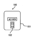
- the front view and side view which show the external appearance of the adapter for electric power supply which concerns on one Embodiment of this invention.
- the side view which shows the external appearance of the adapter for the said electric power supply.
- the functional block diagram which shows one structural example of the adapter for electric power supply.
- the sequence flow figure which shows an example of the procedure registered in advance from the portable communication terminal to the power supply adapter.
- Explanatory drawing which shows an example of the prior registration screen displayed on the display part of a portable communication terminal.
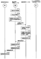
- the sequence flow figure which shows an example of the procedure which controls the adapter for electric power supply from a portable communication terminal, and supplies electric power to household appliances.
- Explanatory drawing which shows an example of a format of an adapter connection request signal.
- Explanatory drawing which shows an example of the electric power supply relevant information memorize
- sequence flow figure which shows an example of the procedure which requests
- Explanatory drawing which shows an example of the format of an electric power supply related information request
- Explanatory drawing which shows the relationship between the adapter for electric power supply which concerns on other embodiment of this invention, household appliances, and a power line.
- the front view of the adapter for the same electric power supply. 1 is a schematic configuration diagram of a power supply system according to an embodiment of the present invention.
- the graph which shows an example of the charge characteristic of a lithium ion battery.
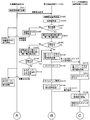
- the sequence flowchart which shows a part of charge procedure which charges the battery of an electric vehicle from the electrical outlet for charge of an electric power output device.
- the sequence flowchart which shows the remaining one part of the charge procedure.
- Explanatory drawing which shows an example of the format of the signal transmitted / received by the same electric power supply system.
- Explanatory drawing which shows the example of 1 structure of the other electric power supply system which concerns on one Embodiment of this invention.
- the block diagram which shows the example of 1 structure of the charge management server in the same electric power supply system.
- An explanatory view showing an example of battery history information The block diagram which shows the example of 1 structure of the charge control apparatus in the same electric power supply system.
- the sequence flowchart which shows an example of the pre-registration process in the same electric power supply system.
- Explanatory drawing which shows an example of a signal format. The sequence flow figure showing an example of the charge processing in the power supply system.
- FIG. 1A and 1B are a front view and a side view, respectively, showing the external appearance of a power supply adapter according to an embodiment of the present invention.
- the power supply adapter 100 is a general-purpose outlet as a power output unit into which a plug of an electric device such as a home appliance as a power supply target device that supplies power can be inserted in front of the housing 101. 102.
- a general-purpose plug 104 as a power input unit is provided on the back side of the casing 101.
- the general-purpose plug 104 of the power supply adapter 100 is used by being inserted into a general-purpose outlet of a commercial power line at home or the like.
- FIG. 2 is a functional block diagram of the power supply adapter 100.
- FIG. 2 also shows a portable communication terminal 200 such as a mobile phone, a general-purpose outlet 300 connected to the power line 500 from the power generation device 600, and a general-purpose plug 401 of the home appliance 400 as a power supply target device.
- a portable communication terminal 200 such as a mobile phone
- a general-purpose outlet 300 connected to the power line 500 from the power generation device 600
- a general-purpose plug 401 of the home appliance 400 as a power supply target device.
- examples of the home appliance 400 include an electric refrigerator and an air conditioner.
- a power supply line 105 from the general-purpose plug 104 to the general-purpose outlet 102, a switch unit 106 for opening and closing the power supply line 105, a control unit 109, a timer Unit 110, storage unit 111, collation unit 112, wireless communication unit 113, and antenna 114.
- the switch unit 106 can be configured by a switch having a normally open relay contact, for example.
- the control unit 109 and the collation unit 112 can be configured by, for example, a general-purpose microcomputer including a CPU or the like, a dedicated IC circuit element, or the like.
- the control unit 109 and the collation unit 112 may be configured to read a predetermined program stored in the storage unit 111 and execute data processing and control according to the program.
- the storage unit 111 can be configured by a semiconductor memory such as a RAM or a ROM, for example.
- the portable communication terminal 200 wirelessly communicates with the power supply adapter 100 to identify a general-purpose outlet 300 of the power line 500 as a power supply source identification information, a general-purpose outlet ID that can identify the household appliance 400 A user ID or the like that can identify a user who uses the home appliance 400 is transmitted to the power supply adapter 100, or power supply related information such as a usage time of the home appliance 400 is received from the power supply adapter 100. can do.
- the general-purpose outlet ID includes identification information of the power company that is the power supply company, identification information of the power resale company that purchases power from the power company and resells the power to be supplied from the general-purpose outlet 300, and general-purpose information of the power line 500. Identification information of a power supply management company that manages the outlet 300 may be included.
- the mobile communication terminal 200 transmits the power company identification information, the power resale company identification information, or the power supply management company identification information to the power supply adapter 100 instead of the general-purpose outlet ID. May be.
- the control unit 109 transmits and receives control data to and from other units such as the switch unit 106, the timer unit 110, the storage unit 111, the collation unit 112, and the wireless communication unit 113, thereby controlling each unit, program, and data. Read or write.
- the timer unit 110 When the timer unit 110 receives an adapter connection request from the mobile communication terminal 200, the timer unit 110 presets the use time included in the adapter connection request and starts the timer simultaneously with the start of energization of the home appliance 400. When the timer expires due to the expiration of the usage time, a time-up signal is output to the control unit 109. Receiving this time-up signal, control unit 109 performs control to turn off switch unit 106 (relay opening), and ends energization of home appliance 400.
- the storage unit 111 receives, from the control unit 109, a general-purpose outlet ID of the general-purpose outlet 300, a home-apparatus device ID of the home-apparatus device 400, a user ID that uses the home-apparatus device 400, information including the usage time of the home-apparatus device 400, and the like. These pieces of information are stored.
- the collation unit 112 detects whether or not the user ID received from the mobile communication terminal 200 matches the user ID stored in the storage unit 111, and outputs a coincidence signal to the control unit 109 if they match. . Receiving the coincidence signal, the control unit 109 performs control to turn on the switch unit 106 (relay closed). On the other hand, if the user IDs do not match, a mismatch signal is output to the control unit 109.
- the wireless communication unit 113 can communicate with the mobile communication terminal 200 via the antenna 114 by wireless communication with a predetermined frequency and communication method.
- a communication method performed by the wireless communication unit 113 for example, via infrared communication, Bluetooth, ZigBee, or a wireless LAN short-range wireless communication method such as WiMAX or WiFi, or a mobile communication network such as a cellular method or PHS.
- a communication method can be adopted. From these communication methods, an appropriate communication method considering the convenience, communication cost, etc. according to the purpose of use can be selected and used for communication with the mobile communication terminal 200.
- FIG. 3 is a sequence flow diagram illustrating an example of a procedure for pre-registering information such as a user ID from the mobile communication terminal 200 to the power supply adapter 100.
- the user uses the mobile communication terminal 200 to specify a user ID for operating the home appliance, a mobile terminal ID as identification information of the mobile communication terminal 200 used by the user, a general-purpose outlet ID, a home appliance ID, and the like. These items are input, and a pre-registration request signal to which the input information and the information type indicating pre-registration are added is transmitted to the power supply adapter 100 (step 101).
- the power supply adapter 100 When the power supply adapter 100 receives the pre-registration request signal from the mobile communication terminal 200 (step 102), the power supply adapter 100 stores the user ID, mobile terminal ID, general-purpose outlet ID, and home appliance ID included in the pre-registration request signal. 111 (step 103), and transmits a pre-registration completion signal to the mobile communication terminal 200 as a response to the pre-registration request signal (step 104). Then, the mobile communication terminal 200 receives the pre-registration completion signal from the mobile communication terminal 200, and the pre-registration process is completed (step 105). In addition, when using home appliances jointly by a plurality of users, it may be pre-registered using a joint user ID set in advance for the plurality of users instead of the user ID.
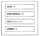
- FIG. 4 is an explanatory diagram illustrating an example of a pre-registration screen displayed on the display unit of the mobile communication terminal 200.
- the pre-registration screen of this example includes a user ID, a user portable terminal ID, a general-purpose outlet ID on the power supply side to which the power supply adapter 100 is connected, and a home appliance ID.
- the pre-registration screen may be registered in advance in a management server connected to a communication network in which the mobile communication terminal 200 can communicate, and a screen downloaded by the mobile communication terminal 200 accessing the management server may be used. Good.
- FIG. 5 is a sequence flow diagram illustrating an example of a procedure for controlling the power supply adapter 100 from the mobile communication terminal 200 to supply power to the home appliance 400.
- the mobile communication terminal 200 supplies an adapter connection request signal as a control request for starting power supply by the power supply adapter 100 and the power source of the home appliance 400.
- a home appliance ON signal for turning ON is transmitted to the power supply adapter 100 (step 201).
- the adapter connection request signal includes the general-purpose outlet ID of the general-purpose outlet 300 to which the power supply adapter 100 is connected, the user ID of the user of the mobile communication terminal 200, and the household appliance 400 connected to the power supply adapter 100. It includes the device ID and usage time (power supply scheduled time).
- the home appliance ON signal includes a home appliance ID, an ON time, and an OFF time. The adapter connection request signal may be transmitted including the home appliance ON signal.
- the adapter for power supply 100 receives the adapter connection request signal and the home appliance ON signal (step 202)
- the user ID included in the received adapter connection request signal and the use stored in the storage unit 111 are used.
- the collation unit 112 collates the person ID (step 203). If the user IDs do not match and the collation result is NG (No in step 204), the power supply adapter 100 transmits a connection request NG signal to the mobile communication terminal 200 (step 205).
- the portable communication terminal 200 returns to the standby state without using the home appliance 400 via the power supply adapter 100 (step 206).
- the power supply adapter 100 stores the general-purpose outlet ID, user ID, home appliance ID, and usage time information by the control unit 109. It is stored in the unit 111 (step 207), the switch unit 106 is turned on (step 208), and the home appliance ON signal is controlled to be transmitted to the home appliance 400. Thereby, the supply of electric power to the home appliance 400 is started, and the power of the home appliance 400 is turned on (step 209).
- the power supply adapter 100 controls the control unit 109 to set the usage time of the home appliance 400 and to start measuring the power supply time by the timer unit 110 (step 210).
- the power supply adapter 100 turns off the switch unit 106 by the control unit 109 (step 212). Control is performed to transmit the home appliance OFF signal to home appliance 400. Thereby, the supply of electric power to the home appliance 400 is stopped and the power of the home appliance 400 is turned off (step 213).
- the power supply adapter 100 controls the control unit 109 to update the power supply related information stored in the storage unit 111 (step 214) and transmit a use completion signal to the mobile communication terminal 200 (step 214). Step 215).
- the mobile communication terminal 200 receives the use completion signal from the power supply adapter 100, the portable communication terminal 200 ends the use of the home appliance 400 via the power supply adapter 100 (step 216).
- the home appliance 400 directly receives the home appliance ON signal from the mobile communication terminal 200, sets the internal timer based on the ON time and OFF time included in the home appliance ON signal,
- the home appliance 400 itself may be configured to control power ON / OFF.
- notice information indicating that the time is up in another 5 minutes is transmitted from the power supply adapter 100 to the mobile communication terminal 200. Also good. Thereby, the user can recognize in advance that the power source of the electric device 400 is turned off, and can perform an operation of extending the usage time as necessary.
- FIG. 6 is an explanatory diagram showing an example of the format of the adapter connection request signal.
- the adapter connection request signal of this example includes an information type indicating an adapter connection request, a general-purpose outlet general-purpose outlet ID to which the power supply adapter 100 is connected, a user ID of the user of the mobile communication terminal 200, It includes a home appliance ID for identifying the home appliance 400 to be supplied with power, a rating of the home appliance 400, and a usage time (power supply time) of the home appliance 400.
- the rating of the home appliance 400 includes, for example, power consumption of the home appliance.
- FIG. 7 is an explanatory diagram showing an example of power supply related information as storage information stored in the power supply adapter 100.
- the power supply related information stored in the storage unit 111 of the power supply adapter 100 includes the user ID of the user who uses the power supply, the use start time of the power, and the general-purpose outlet 300 used. It includes the outlet ID, the household appliance ID of the used household appliance 400, the rated power of the household appliance 400, the cumulative usage time, and the cumulative usage power amount.
- the accumulated power consumption can be calculated from the rated power and usage time of home appliance 400.
- the accumulated used power amount may be calculated based on the power amount detected by the power amount measuring unit.
- the shared use is calculated when calculating the accumulated usage time and the accumulated power amount for each user. The value divided by the number of people to perform may be used.
- FIG. 8 is a sequence flow diagram illustrating an example of a procedure for requesting power supply related information from the mobile communication terminal 200 to the power supply adapter 100.
- the mobile communication terminal 200 transmits a storage information display request signal to the power supply adapter 100 (step 301).
- the power supply adapter 100 receives the stored information display request signal from the mobile communication terminal 200 (step 302)
- the power supply adapter 100 searches the power supply related information stored in the storage unit 111 (step 303), and the corresponding power supply related Information is transmitted to the mobile communication terminal 200 (step 304).
- the search for the power supply related information is performed, for example, so as to search the accumulated use time and the accumulated use power amount by using the user ID as a key.
- the mobile communication terminal 200 receives the power supply related information from the power supply adapter 100 (step 305) and displays it on a display device such as a liquid crystal display provided in the mobile communication terminal 200 (step 306).
- FIG. 9 is an explanatory diagram showing an example of the format of the stored information display request signal.
- the format of the stored information display request signal includes an information type indicating that it is the stored information display request signal, and a user ID for identifying the user of the mobile communication terminal 200.
- the power supply related information that is requested from the mobile communication terminal 200 to the power supply adapter 100 and displayed on the mobile communication terminal 200 is the information when a specific user uses the home appliance 400 through the power supply adapter 100.
- information indicating the open / closed state of the power supply line 105 of the power supply adapter 100, that is, the ON / OFF state of power supply to the home appliance 400 may be used.
- the power supply adapter 100 receives the adapter connection request signal (control request) including the user ID and the universal outlet ID of the universal outlet 300 from the mobile communication terminal 200 operated by the user. Then, based on the adapter connection request signal, the power supply line 105 of the power supply adapter 100 is opened and closed to control power supply to the home appliance 400, and power supply related to power supply by opening and closing the power supply line 105 Information, a user ID, and a general-purpose outlet ID are associated with each other and stored in the storage unit 111. Information stored in the storage unit 111 enables management of the amount of electric power supplied from the general-purpose outlet 300 to the household electrical appliance 400 for each user (for example, charging / billing for power usage for each user).
- the power supply adapter 100 is excellent in general versatility.
- the power supply adapter 100 further includes a power amount measuring unit that measures the power amount of power supplied through the power supply adapter 100. It may be configured. In this case, the cumulative power consumption amount may be calculated based on the power amount detected by the power amount measurement unit. Further, the power supply adapter 100 may be configured to further include a display unit capable of displaying the accumulated use time and the accumulated use power amount when the user uses the power.
- the power supply adapter 100 may be divided into a plurality of adapter components.
- FIG. 10 is an explanatory diagram showing a relationship among the power supply adapter 100, the home appliance 400, and the power line 500 according to another embodiment of the present invention
- FIG. 11 is a front view of the power supply adapter 100.
- the power supply adapter 100 includes a power line side adapter 120 having a power input unit and a device side adapter 130 having a power output unit as a plurality of adapter components.
- the power line adapter 120 is fixed to the building wall 700 and the like, and its power input unit is configured to be connected to the commercial power line 500 without using a general-purpose outlet.
- the power line adapter 120 has a special-shaped relay outlet 121, and the power supply line 105, the switch unit 106, the control unit 109, the timer unit 110, the storage unit 111, the verification unit 112, and the wireless communication unit 113 described above. And an antenna 114.
- the device-side adapter 130 has a general-purpose outlet (not shown) that can be connected to the general-purpose plug 401 of the home appliance 400 and a special-shaped relay plug 131 that can be connected to the relay outlet 121 of the power line-side adapter 120. is doing.
- the relay outlet 121 of the power line side adapter 120 and the relay plug 131 of the device side adapter 130 can be engaged with each other so that power can be transmitted.
- the relay outlet 121 of the power line side adapter 120 is configured not to be engaged with the general-purpose plug 401 of the home appliance 400, that is, so that the general-purpose plug 401 cannot be inserted and connected.
- the relay plug 131 of the device-side adapter 130 is configured not to be engaged with a commercial general-purpose outlet, that is, not to be plugged into the general-purpose outlet.
- the power line adapter 120 cannot be used unless the user has the dedicated device adapter 130, and power is supplied via the power supply adapter 100 (power line adapter 120, device adapter 130). Management of users to be used can be performed more strictly.
- the user wants to supply power to the home appliance 400 without going through the power supply adapter 100, it is possible to prevent the user from mistakenly connecting the general-purpose plug 401 of the home appliance 400 to the power supply adapter 100. .
- an IC tag having an RFID (Radio Frequency Identification) function is attached to the device-side adapter 130, and information is read from the IC tag to the power line-side adapter 120 or information is sent to the IC tag.
- An R / W device information reading / writing device
- the power line side adapter 120 automatically recognizes the device side adapter 130 when the device side adapter 130 used by the user is connected, and reads information from the IC tag of the device side adapter 130. Can write.
- the device-side adapter 130 can be specified and authenticated, and more detailed management of the user of the mobile communication terminal 200 and charging of the user with an electric bill can be easily performed.
- the example applied to the home appliance 400 such as an electric refrigerator or an air conditioner as a device that uses power by connecting to the power supply adapter 100 has been described.
- the present invention is not limited to this, and the power supply target device is also applicable to office devices such as copiers other than home appliances, other electric devices such as mobile phones, and electric vehicles such as electric vehicles. And the same effect can be obtained.
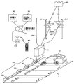
- FIG. 12 is a schematic configuration diagram of a power supply system according to an embodiment of the present invention.
- the present embodiment is an example in which a power output device is installed in a parking lot of a store such as a supermarket, and a battery of an electric vehicle as an electric vehicle that is a power supply target device is charged by the power output device.
- the parking lot P has a plurality of parking spaces in which N electric vehicles can be parked. It is assumed that the vehicle is parked in one parking space and the battery of the electric vehicle 101 is charged.
- a communication control unit 200 constituting an electric power output device is installed.
- N charging outlets 300 are connected to the communication control unit 200 and the user inserts the charging plug 111 of the electric vehicle 101 into the charging outlet 301 and operates the portable communication terminal 400 such as a mobile phone, the electric vehicle The charging of the battery 101 is started.
- the communication control unit 200 includes two power lines 500, the first power line transformer 521 to the first power line 501 of the first power pole 511 and the second power line transformer 522 to the second power line 502 of the second power pole 512. Are connected, and the electric power transmitted from the power generation device 600 is transformed to a predetermined voltage and supplied.
- the communication control unit 200 is configured to be able to communicate with the power supply management server 700 through a broadband line 550 such as an ADSL line.
- the power supply management server 700 can communicate with a customer management server 900 as a user management server via a mobile phone communication network 800 as a communication network.
- a wireless base station 810 for performing wireless communication with the mobile communication terminal 400 is connected to the mobile phone communication network 800.
- the customer management server 900 is a server that stores and manages information on subscribers who are customers of communication services using the mobile communication terminal 400, and stores and manages information related to users of power supply by the power supply system. Also used as a user management server. Further, the customer management server 900 receives the charging power usage information from the power supply management server 700, and based on the portable communication terminal ID that can identify the portable communication terminal 400, the customer management server 900 calculates the charging power fee used by the user. It has a billing processing function for billing so that it is settled with a predetermined bank account or credit card of the user. Note that the customer management server 900 does not have a billing processing function, and the customer management server 900 generates a billing signal (payment signal) for billing processing such as user information and charging power usage fee information. Alternatively, it may be transmitted to a billing server provided separately and the billing server may perform billing processing.
- a billing signal payment signal
- FIG. 13 is a functional block diagram of the communication control unit 200 constituting the power output apparatus.
- the communication control unit 200 includes a main control unit 201, a switch control unit 202, a communication unit 203, a power meter 204, a changeover switch 205, a current detection unit 206 provided on the first power line 501, and N number of first control units. 1 switch sections 211 to 21N, a current detection section 207 provided on the second power line 502, and N second switch sections 221 to 22N.
- the current detection unit 206 and the current detection unit 207 can be configured with a current transformer, for example.
- the main control unit 201 can be configured by, for example, a general-purpose microcomputer including a CPU, a dedicated IC circuit element, or the like.
- each switch unit via the switch control unit 202 so that power is supplied from the outlet corresponding to the outlet identification information included in the control request. It controls opening / closing of 211 to 21N and 221 to 22N, and transmits power usage information related to the usage of power supplied from an outlet to the power supply management server 700.
- the switch control unit 202 controls opening and closing of the first switch units 211 to 21N and the second switch units 221 to 22N based on a control command from the main control unit 201.
- the communication unit 203 communicates with the power supply management server 700 via a broadband line such as an ADSL line.
- the power meter 204 is connected to one of the current detection unit 206 of the first power line 501 and the current detection unit 207 of the second power line 502 by the changeover switch 205.
- the changeover switch 205 connects the wattmeter 204 and the current detection unit 206 of the first power line 501
- the wattmeter 204 changes the current and voltage flowing through the first power line 501 detected by the current detection unit 206. Based on this, the amount of power supplied through the first power line 501 is measured, and the measured amount of power is transmitted to the main control unit 201.
- the changeover switch 205 connects the wattmeter 204 and the current detection unit 207 of the second power line 502
- the wattmeter 204 detects the current and voltage flowing through the second power line 502 detected by the current detection unit 207. Based on the above, the amount of power supplied through the second power line 502 is measured, and the measured amount of power is transmitted to the main control unit 201.
- the main control unit 201 calculates the amount of power required for charging the battery of the electric vehicle 101 based on the measured value of the amount of power by the wattmeter 204.
- the ON timing of power supply to the charging outlets 301 to 30N does not overlap in the switch control unit 202.
- the first switch sections 211 to 21N may be controlled.
- the switch control unit 202 determines the ON timing of power supply to the charging outlets 301 to 30N.
- the second switch units 221 to 22N may be controlled so that they do not occur.
- the first switch part 211 and the second switch part 221 can be constituted by, for example, a relay type switch having a normally open type relay contact. When OFF, neither the first power line 501 nor the second power line 502 is connected and power is not supplied to the charging outlet 301. However, when a control signal is received from the switch control unit 202, the first switch unit 211 and the second switch unit 221 are provided. Is turned ON, and either the first power line 501 or the second power line 502 is connected to supply power to the charging outlet 301.
- the other first switch sections 212 to 21N and second switch sections 222 to 22N have the same configuration.
- the selection of which of the charging outlets 301 to 30N is connected to the first power line 501 or the second power line 502 is made by first connecting the charging outlets 301 to 30N to the first power line 501 and the power measurement result of the wattmeter 204 is the first.
- the load is distributed by controlling to connect to the second power line 502.
- the first switch unit 211 ⁇ is connected so as to continue the power supply by connecting to the other power line capable of supplying power.
- 211N and the second switch sections 221 to 22N can be switched, thereby improving the reliability of power supply.
- FIG. 14 is a graph showing the charging characteristics of a small lithium ion battery from a fully discharged state to almost a full charge (for example, see the BAYSUN website (http://www.baysun.net/)).
- the electric power (dotted line) can be obtained from the current (thin solid line) and the voltage (thick solid line), and the integrated electric energy (dotted line) required for charging can be obtained from this value and the charging time.
- the charging characteristics the rate of decrease in the current value with the lapse of the charging time
- the accumulated power required for charging can be calculated from the charging time, the power at the start of charging, the charging completion time, and the power. Can be calculated.
- 15 and 16 are sequence flow diagrams illustrating an example of a procedure for operating the mobile communication terminal 400 to charge the battery of the electric vehicle 101 from the charging outlet 301.
- the user first operates the mobile communication terminal 400 to transmit a connection request signal to the power supply management server 700 (step 101).
- This connection request signal includes the information type indicating the connection request, the mobile communication terminal ID, the outlet ID of the charging outlet 301 used for charging, the battery rating including the maximum current and maximum voltage during charging, and the charging usage time. It is.
- the power supply management server 700 collates the mobile communication terminal ID included in the connection request signal with the preset mobile communication terminal ID (step 103), and the collation result Is NG (No in Step 104), a connection request NG signal is transmitted (Step 105), and this NG signal is received by the mobile communication terminal 400, and the process ends (Step 106).
- the power supply management server 700 reads the value of the wattmeter 204 via the main control unit 201 of the communication control unit 200 ( Step 107). At this time, the wattmeter 204 measures the power of the first power line 501.
- the selector switch 205 is switched to change the value of the wattmeter 204.
- the wattmeter 204 measures the power of the second power line 502.
- the power of the wattmeter 204 exceeds the rated output (No in step 110)
- the power of the second power line 502 exceeds the rated output
- charging is not possible, so charging due to output over NG
- the signal is transmitted (step 111), and the mobile communication terminal 400 receives this NG signal and ends (step 112).
- the power supply management server 700 switches the first switch unit 211 or the second switch unit 221 to ON.
- An ON command signal is transmitted to the communication control unit 200 of the power output apparatus (step 113).
- the switch ON command signal may include an outlet ID and a power line ID in addition to information on the switch to be turned ON.
- power is supplied from the second power line 502 to the charging outlet 301.
- the switch control unit 202 When the communication control unit 200 of the power output apparatus receives the ON command signal of the first switch unit 211 or the second switch unit 221, the switch control unit 202 performs control to turn on the designated switch unit (step 114). , S115). In addition, the power supply management server 700 starts a timer for measuring the charging use time (step 116). When the timer expires, a switch OFF command signal is transmitted to the communication control unit 200 (step 117, S118). The switch control unit 202 that has received this switch-off command signal performs control to turn off the designated switch (step 119, S120). The switch OFF command signal may include an outlet ID and a power line ID in addition to information on the switch to be turned OFF. At this time, a charging completion signal may be transmitted from the power supply management server 700 to the mobile communication terminal 400.
- the power supply management server 700 which has been charged and has transmitted a switch OFF command signal, executes a charging process for calculating a charging electricity charge.
- the power supply management server 700 integrates the charging usage time used by the user (step 121). Based on this charging usage time, the charging characteristics of the battery mounted on the user's electric vehicle, the power at the start of charging, and the power at the completion of charging, the accumulated power required for charging (Watt ⁇ Hour) is calculated. (Step 122).
- the power supply management server 700 calculates a charging power charge by adding a charging fee to the amount calculated by the product of the calculated integrated electric energy and the unit price of electricity charge (electric cost per 1 Watt ⁇ Hour).
- the mobile communication terminal ID is added to the charge charge request signal including the charge power charge information and transmitted to the customer management server 900 (step 123).
- the customer management server 900 Upon receiving the charge charge request signal from the power supply management server 700, the customer management server 900 adds the charge power charge to the charge for using the mobile communication terminal 400 of the user corresponding to the mobile communication terminal ID and charges / charges the charge. As a result, the charging power charge is settled (step 124, S125). Then, the customer management server 900 transmits a settlement result signal to the power supply management server 700 (step 126).
- the power supply management server 700 that has received the settlement result signal transmits the settlement result signal to the mobile communication terminal 400 (step 127, S128).
- the control ends when the mobile communication terminal 400 receives the settlement result signal (step 129).
- the user can confirm the charge power charge for charging the battery of the electric vehicle 101 on the display unit of the mobile communication terminal 400.
- FIG. 17 is an explanatory diagram showing an example of components of an information format such as a connection request signal transmitted and received by the power supply system.
- the connection request signal includes an information type indicating a connection request, a mobile communication terminal ID, an outlet ID, a battery rating, and a charging usage time.
- the switch ON command includes information type, outlet ID, power line ID, and charging usage time.
- the switch OFF command includes an information type, an outlet ID, and a power line ID.
- the charging completion signal includes an information type, a mobile communication terminal ID, and a charging usage time.
- the charging charge request signal includes an information type, a mobile communication terminal ID, and a charging power charge.
- the payment result signal includes an information type, a mobile communication terminal ID, and a payment result.
- the power supply management server 700 authenticates the user who uses the power supply from the outlets 301 to 30N provided in the power output apparatus, and communicates the control request used to control the power supply from the outlets 301 to 30N.
- the transmission to the control unit 200 is performed in a centralized manner, and the customer management server (user management server) 900 receives power usage information received from the power supply management server 700 from the outlets 301 to 30N of the power output device. Billing for usage charges for power supply is intensively performed.
- user authentication, control of power supply from each of the outlets 301 to 30N, and billing processing of the power usage fee can be collectively performed without adding an additional function to each of the charging outlets 301 to 30N. it can.
- FIG. 18 is an explanatory diagram showing a configuration example of another power supply system according to an embodiment of the present invention.
- the power supply system of the present embodiment is a power supply system that supplies power to the electric vehicle 100 including the rechargeable battery 101, and includes a plurality of power output devices each having outlets 601, 611, and 621 that output power.
- Charging devices 600, 610, and 620, and a charging management server 500 as a power supply management server that manages power supply from the charging devices 600, 610, and 620 to the electric vehicle.
- the present invention is directed to one set of charging devices, two sets of charging devices, and any number of sets of four or more sets.
- the present invention can also be applied when a device is provided.
- the battery 101 of the electric vehicle 100 is performed by connecting the charging plug 103 at the tip of the charging cable 102 connected to the battery 101 to one of the outlets 601, 611, 621 of the charging devices 600, 610, 620. .
- Outlets 601, 611, and 621 of charging devices 600, 610, and 620 are connected to power line 801 from power generation device 800 via charging control devices 602, 612, and 622, respectively.
- Each charging control device 602, 612, 622 controls power supply supplied from the power line 801 via the outlets 601, 611, 621 based on the control signal received from the charging management server 500 via the control line 501. Do.
- the charge management server 500 is connected to a mobile communication terminal 200 such as a mobile phone used by a user via the wireless access network 300 and the Internet 400, and transmits / receives a signal to / from the mobile communication terminal 200 or uses a power usage fee. Can be settled.
- a mobile communication terminal 200 such as a mobile phone used by a user via the wireless access network 300 and the Internet 400
- the wireless access network include a wireless access network for cellular communication cellular phones, and wireless access complying with IEEE 802.11p (WAVE: Wireless Access in Vehicular Environments), which is a wireless LAN standard for ITS (Intelligent Transport Systems).
- IEEE 802.11p Wi-Fi: Wireless Access in Vehicular Environments
- ITS Intelligent Transport Systems
- FIG. 19 is a block diagram illustrating a configuration example of the charge management server 500.
- the charge management server 500 includes a communication unit 510, a charge control interface unit 520, a storage unit 530, a collation determination unit 540, a search unit 550, and a control unit 560.
- the charge management server 500 may further include a charging processing unit.
- the storage unit 530 can be configured by a semiconductor memory such as a RAM or a ROM.
- the collation determination unit 540, the search unit 550, the control unit 560, and the billing processing unit can be configured by, for example, a general-purpose microcomputer including a CPU, a dedicated IC circuit element, or the like. Further, the collation determination unit 540, the search unit 550, the control unit 560, and the billing processing unit may be configured to read a predetermined program stored in the storage unit 530 and execute data processing and control according to the program. Good.
- the storage unit 530 can be configured by a semiconductor memory such as a RAM or a ROM.
- the communication unit 510 communicates with the user's mobile communication terminal 200 via the Internet 400 and the wireless access network 300.
- the charging control interface unit 520 communicates with the charging control devices 602, 612, and 622 of the charging devices 600, 610, and 620 through wired or wireless communication.
- the storage unit 530 stores history information of power supply to the user's electric vehicle 100 in association with the mobile terminal ID as terminal identification information for identifying the mobile communication terminal 200. This power supply history information is updated after the end of charging.
- the power supply history information includes, for example, a portable terminal ID as shown in FIG. 20, a vehicle ID as vehicle identification information for identifying the electric vehicle 100, and a battery as battery identification information for identifying the battery 101 provided in the electric vehicle 100. It includes ID, rating of the battery 101, battery usage start date, number of times of charging, charging date, number of days elapsed since the previous charging date, travel distance from the previous charging date, battery environment temperature, remaining charge before charging, and charging time.
- the collation determination unit 540 determines to allow the use of power supply when the mobile terminal ID included in the power usage request matches the mobile terminal ID stored in the storage unit 530, and If the two portable terminal IDs do not match, it is determined not to allow the use of power supply.
- the search unit 550 searches for charging history information as power supply history information corresponding to the mobile terminal ID stored in the storage unit 530. For example, when the search unit 550 receives a charge request signal as a power use request from the mobile communication terminal 200, the search unit 550 supports the mobile terminal ID using the mobile terminal ID, the vehicle ID, and the battery ID included in the signal as keys. The charging history information of the battery 101 to be searched is searched.
- the three information of the mobile terminal ID, the vehicle ID, and the battery ID are used as a key when the owner of one mobile communication terminal 200 has one or more electric vehicles or the battery in one vehicle. In this case, the electric vehicle 100 and the battery 101 to be charged are correctly recognized and the corresponding charging history information can be reliably searched.
- the control unit 560 sets a power supply condition to the user's electric vehicle 100 based on the charging history information searched by the search unit 550, and sends the charge control information including the power supply condition to the charge control interface unit 520. Then, control is performed so as to transmit to the charging control device of the charging device to which the charging plug 103 from the user's electric vehicle 100 is connected.
- the charging processing unit receives information indicating that the power supply to the electric vehicle 100 by the user is completed from the charging device, and then determines the power supply condition (for example, vehicle ID, battery rating, etc.) and the power supply time. Based on this, a billing process is performed to settle the usage fee (charging fee) for power supply to the electric vehicle 100 of the user.
- the power supply condition for example, vehicle ID, battery rating, etc.
- FIG. 21 is a block diagram illustrating a configuration example of the charging control devices 602, 612, and 622. Although FIG. 21 shows the charge control device 602, a similar configuration can be adopted for the other charge control devices 612 and 622.
- the charging control device 602 includes a communication unit 603, a control unit 604, and a charging voltage / current adjustment unit 605.
- the control unit 604 can be configured by, for example, a general-purpose microcomputer including a CPU or the like, a dedicated IC circuit element, or the like.
- the control unit 604 may be configured to read a predetermined program stored in a memory or the like and execute data processing and control according to the program.
- the communication unit 603 communicates with the charge management server 500 based on the control command received from the control unit 604, and transmits / receives charge control information and the like.
- the charging voltage / current adjustment unit 605 includes, for example, a switch, a regulator, and other circuits, and adjusts the power supplied from the power line 801 to a predetermined voltage and current based on a control command received from the control unit 604. Output.
- the control unit 604 receives a control request from the charge management server 500, the control unit 604 adjusts the charging voltage / current so that power is supplied from the outlet 601 to the user's electric vehicle 100 based on the charging condition included in the control request.
- the unit 605 is controlled.
- control unit 604 receives the charging control information by the communication unit 603 communicating with the charging management server 500, and adjusts the power of the power line 801 to the charging voltage / current and charging time of the battery suitable for the battery to be charged. And control to supply to the outlet 601.
- FIG. 22 is a sequence flow diagram illustrating an example of a procedure for pre-registering information such as a mobile terminal ID from the mobile communication terminal 200 to the charge management server 500.
- the user inputs predetermined registration information (for example, vehicle ID, battery ID, charge management server ID, battery rating, battery use start date) with the mobile communication terminal 200, and the input information and pre-registration. Is transmitted to the charge management server 500 (step 101). As illustrated in FIG.
- the pre-registration signal includes an information type, a portable terminal ID, a vehicle ID, a battery ID, a charge management server ID, a battery rating, and a battery use start date.
- the address information and ID information of the charge management server 500 may be acquired by, for example, downloading a predetermined web screen.
- the mobile terminal ID may be automatically added by the mobile communication terminal 200.
- the charge management server 500 determines whether or not pre-registration has already been performed (step 103). If not pre-registered (NO in step 103), After newly registering the portable terminal ID, vehicle ID, battery ID, battery rating (charging voltage and current, charging time), and battery use start date included in the pre-registration signal (step 104), the registration completion signal is sent to the portable communication terminal. 200 (step 105). On the other hand, if the pre-registration has already been completed (YES in step 103), the charging management server 500 updates the registration contents with the information included in the pre-registration signal received this time (step 106), and carries the registration completion signal. It transmits to the communication terminal 200 (step 105). The mobile communication terminal 200 receives the registration completion signal and ends the control (step 107).
- FIG. 24 is a sequence flow diagram illustrating an example of a charging process in the power supply system.
- the mobile communication terminal 200 transmits a charge request signal as a power use request to the charge management server 500 (step 201).
- the charge request signal includes an information type indicating that it is information of a charge request, a portable terminal ID, a vehicle ID, a battery ID, a charge management server ID, and an outlet ID of an outlet to be charged. including.
- the charge management server 500 When the charge management server 500 receives the charge request signal from the mobile communication terminal 200 (step 202), the charge management server 500 collates the mobile terminal ID included in the charge request signal with the mobile terminal ID registered in advance (step 203). If the collation result is not good, that is, if the portable terminal ID that matches the received portable terminal ID is not registered (NO in step 204), a collation NG signal is transmitted to the portable communication terminal 200 (step 205).
- the charge management server 500 displays the battery history information for the mobile terminal ID. Search (step 206). Thereafter, the charge management server 500 sets a battery charge condition based on the retrieved battery history information, and transmits a battery charge condition signal including the battery charge condition to the mobile communication terminal 200 (step 207).
- the battery charge condition signal includes an information type indicating that the battery charge condition is information, a mobile terminal ID, a vehicle ID, a charge management server ID, a battery rating (voltage / current value, Charging time).
- the mobile communication terminal 200 When the mobile communication terminal 200 receives the battery charge condition signal from the charge management server 500 (step 208), if the battery rated current / voltage / charge time included in the received battery charge condition signal is correct as the charge condition, the mobile communication terminal 200 receives the received battery. Without changing the rating, a battery charge condition confirmation signal as illustrated in FIG. 23 is transmitted to the charge management server 500 (step 209).
- the mobile communication terminal 200 confirms the battery charging condition including the current / voltage / charging time as the desired charging condition. A signal is transmitted to the charge management server 500 (step 209).
- the charging management server 500 When the charging management server 500 receives the battery charging condition confirmation signal from the mobile communication terminal 200 (step 210), the charging management server 500 sends a battery to the charging control device of the predetermined charging device (in the example of FIG. 24, the charging control device 602 of the charging device 600). A charge control signal is transmitted (step 211). As illustrated in FIG. 23, the battery charge control signal includes a mobile terminal ID, a vehicle ID, a battery rating (voltage / current value, charge time), an outlet, in addition to an information type indicating that the information is battery charge control information. ID and charging control device ID are included.
- the charge control device 602 When receiving the battery charge control signal from the charge management server 500 (step 212), the charge control device 602 sets the battery charge condition included in the battery charge control signal (step 213), and the battery 101 of the user's electric vehicle 100 is set. Is charged (step 214). When the charging is completed, the charging control device 602 transmits a battery charging completion signal to the charging management server 500 (step 215).
- the battery charge completion signal is not only an information type indicating that the battery charge is completed, but also a mobile terminal ID, a vehicle ID, a battery ID, a battery rating, an outlet ID, and a charge control device ID. , Environmental temperature, remaining charge before charging, and charging date and time.
- the charge management server 500 uses the information included in the received battery charge completion signal to store the battery charge history stored in the storage unit 530. Updating is performed (step 217), a charging process for adjusting the battery charging fee based on the vehicle ID is executed (step 218), and a charging fee adjustment completion signal is transmitted to the mobile communication terminal 200 (step 219).
- the charging fee settlement completion signal is an information type indicating that the charging fee settlement is completed, as well as a mobile terminal ID, a vehicle ID, a battery ID, a battery rating, an outlet ID, and a settlement amount. including.
- the mobile communication terminal 200 receives the charging fee settlement completion signal from the charging management server 500 and completes charging (step 220).
- the charging fee may be settled with the ETC card using the ETC card ID instead of the vehicle ID.
- the charge request signal as the power use request transmitted from the mobile communication terminal 200 to the charge management server 500 includes the ID of the ETC card attached to the electric vehicle 100 and is charged by the power supply management server 500.
- the processing unit 570 transmits the ID of the ETC card and information on the usage fee for power supply to the electric vehicle 100 to the management server of the ETC card via the Internet or a dedicated line.
- charging of the user's electric vehicle 100 is performed based on the portable terminal ID included in the charging request signal received from the portable communication terminal 200 of the user. Since it is possible to determine whether or not the use is permitted, it is easy to authenticate the use of the electric vehicle 100 for charging. In addition, when it is determined that the use of charging is permitted, battery history information corresponding to the mobile terminal ID of the mobile communication terminal 200 of the user is searched, and the user's electric power is searched based on the searched battery history information. Since the battery charging condition for the vehicle 100 can be set, it is easy to set the battery charging condition when charging the user's electric vehicle 100. As described above, since it is easy to authenticate the use of charging of the electric vehicle 100 and to set the battery charging condition when charging the electric vehicle 100, the convenience of the user who uses the charging of the electric vehicle 100 is improved. be able to.
Landscapes
- Engineering & Computer Science (AREA)
- Power Engineering (AREA)
- Transportation (AREA)
- Mechanical Engineering (AREA)
- Management, Administration, Business Operations System, And Electronic Commerce (AREA)
- Remote Monitoring And Control Of Power-Distribution Networks (AREA)
- Charge And Discharge Circuits For Batteries Or The Like (AREA)
Abstract
La présente invention se rapporte à un adaptateur de fourniture de puissance jouissant d'une excellente polyvalence, qui permet de gérer la quantité de puissance utilisée pour chacun des utilisateurs de dispositifs électriques.
De façon plus spécifique, la présente invention se rapporte à un adaptateur de fourniture de puissance (100) comprenant : un module d'entrée de puissance (104); un module de sortie de puissance (102); un module de commutation (106) pour ouvrir/fermer des lignes de fourniture de puissance (105) entre le module d'entrée de puissance et le module de sortie de puissance; un module de communication (113) qui est apte à communiquer avec un terminal de communication portable (200); un module de stockage (111); et un module de commande (109). A réception d'une demande de contrôle contenant des informations d'identification d'un utilisateur et des informations d'identification d'un fournisseur de puissance en provenance du terminal de communication portable (200), le module de commande (109) commande : l'ouverture ou la fermeture des lignes de fourniture de puissance (105) sur la base de la demande de contrôle ; l'association d'informations associées relatives à la fourniture de puissance, des informations d'identification d'un utilisateur, et des informations d'identification d'un fournisseur de puissance les unes aux autres ; et le stockage des informations associées dans le module de stockage (111).
Applications Claiming Priority (6)
| Application Number | Priority Date | Filing Date | Title |
|---|---|---|---|
| JP2009136415A JP5302109B2 (ja) | 2009-06-05 | 2009-06-05 | 電力供給システム |
| JP2009-136415 | 2009-06-05 | ||
| JP2009136350A JP2010284037A (ja) | 2009-06-05 | 2009-06-05 | 電力供給用アダプタ |
| JP2009136412A JP5412183B2 (ja) | 2009-06-05 | 2009-06-05 | 電力供給システム |
| JP2009-136412 | 2009-06-05 | ||
| JP2009-136350 | 2009-06-05 |
Publications (1)
| Publication Number | Publication Date |
|---|---|
| WO2010140664A1 true WO2010140664A1 (fr) | 2010-12-09 |
Family
ID=43297797
Family Applications (1)
| Application Number | Title | Priority Date | Filing Date |
|---|---|---|---|
| PCT/JP2010/059467 Ceased WO2010140664A1 (fr) | 2009-06-05 | 2010-06-03 | Adaptateur de fourniture de puissance et système de fourniture de puissance |
Country Status (1)
| Country | Link |
|---|---|
| WO (1) | WO2010140664A1 (fr) |
Cited By (19)
| Publication number | Priority date | Publication date | Assignee | Title |
|---|---|---|---|---|
| JP2012244669A (ja) * | 2011-05-16 | 2012-12-10 | Sony Corp | 電力供給装置および方法、並びにプログラム |
| JP5205541B1 (ja) * | 2012-09-24 | 2013-06-05 | ステラグリーン株式会社 | 電源タップおよび電力制御システム |
| JP2014007954A (ja) * | 2012-06-22 | 2014-01-16 | Lsis Co Ltd | ケーブル一体型充電制御装置に取り付けられるアドオン通信装置、及びその動作方法 |
| JP2015012697A (ja) * | 2013-06-28 | 2015-01-19 | トヨタ自動車株式会社 | 車両および受電装置 |
| CN104331769A (zh) * | 2014-10-29 | 2015-02-04 | 国家电网公司 | 一种基于监控闭环管理的电网有序用电系统及方法 |
| JP2015146162A (ja) * | 2014-02-04 | 2015-08-13 | ソフトバンクモバイル株式会社 | 電力供給システム |
| WO2015145926A1 (fr) * | 2014-03-24 | 2015-10-01 | 日本電気株式会社 | Système d'alimentation en énergie électrique, appareil de commande, appareil récepteur d'énergie électrique, appareil terminal, procédé de régulation d'énergie électrique et support non transitoire lisible par un ordinateur |
| EP2712044A4 (fr) * | 2011-05-16 | 2015-12-23 | Sony Corp | Dispositif, procédé et programme d'alimentation électrique |
| WO2016082621A1 (fr) * | 2014-11-28 | 2016-06-02 | 青岛海尔股份有限公司 | Dispositif électrique disposé dans un compartiment d'un réfrigérateur, et réfrigérateur |
| JP2017117061A (ja) * | 2015-12-22 | 2017-06-29 | ソフトバンク株式会社 | 電力管理システム、電力中継装置、電力管理プログラム及び電力管理方法 |
| US9979347B2 (en) | 2012-08-06 | 2018-05-22 | Kyocera Corporation | Management system, management method, control apparatus, and photovoltaic cell apparatus |
| CN108791900A (zh) * | 2017-05-02 | 2018-11-13 | 松下航空电子公司 | 座椅盒电力管理 |
| US10404083B2 (en) | 2015-05-13 | 2019-09-03 | Guangdong Oppo Mobile Telecommunications Corp., Ltd. | Quick charging method, power adapter and mobile terminal, bidirectional communication using USB interface |
| CN111332142A (zh) * | 2018-12-18 | 2020-06-26 | 现代自动车株式会社 | 充电电缆、与该充电电缆通信的通信装置及其控制方法 |
| WO2020221959A1 (fr) * | 2019-04-29 | 2020-11-05 | Liikennevirta Oy / Virta Ltd | Procédé, appareil et produit programme informatique pour surveiller la consommation d'énergie dans un réseau de charge de véhicule électrique |
| CN116742762A (zh) * | 2023-08-14 | 2023-09-12 | 陕西拓普索尔电子科技有限责任公司 | 充电方法、装置和设备 |
| GB2631101A (en) * | 2023-06-19 | 2024-12-25 | Menashe Julian | Vehicle electric battery charging system |
| JP2025156808A (ja) * | 2024-04-02 | 2025-10-15 | 本田技研工業株式会社 | 給電システムおよび給電方法 |
| JP7807850B1 (ja) * | 2025-08-26 | 2026-01-28 | glafit株式会社 | バッテリー管理システム、バッテリー管理装置、バッテリー管理プログラム、バッテリー管理方法、およびバッテリー |
Citations (6)
| Publication number | Priority date | Publication date | Assignee | Title |
|---|---|---|---|---|
| JPH05227669A (ja) * | 1992-02-14 | 1993-09-03 | Tatsuno Co Ltd | 電気自動車用バッテリー充電装置 |
| JP2002325357A (ja) * | 2001-04-27 | 2002-11-08 | Sharp Corp | モバイルコンセント、電力供給ゲート装置、サーバ装置および電力利用管理システム |
| JP2002354683A (ja) * | 2001-05-29 | 2002-12-06 | Tokyo R & D Co Ltd | バッテリの充電システム |
| JP2006114997A (ja) * | 2004-10-12 | 2006-04-27 | Yasuhiko Oe | 電源タップ |
| JP2007228695A (ja) * | 2006-02-22 | 2007-09-06 | Toyota Motor Corp | 充電装置 |
| JP2008199752A (ja) * | 2007-02-09 | 2008-08-28 | Kyushu Electric Power Co Inc | 充電装置 |
-
2010
- 2010-06-03 WO PCT/JP2010/059467 patent/WO2010140664A1/fr not_active Ceased
Patent Citations (6)
| Publication number | Priority date | Publication date | Assignee | Title |
|---|---|---|---|---|
| JPH05227669A (ja) * | 1992-02-14 | 1993-09-03 | Tatsuno Co Ltd | 電気自動車用バッテリー充電装置 |
| JP2002325357A (ja) * | 2001-04-27 | 2002-11-08 | Sharp Corp | モバイルコンセント、電力供給ゲート装置、サーバ装置および電力利用管理システム |
| JP2002354683A (ja) * | 2001-05-29 | 2002-12-06 | Tokyo R & D Co Ltd | バッテリの充電システム |
| JP2006114997A (ja) * | 2004-10-12 | 2006-04-27 | Yasuhiko Oe | 電源タップ |
| JP2007228695A (ja) * | 2006-02-22 | 2007-09-06 | Toyota Motor Corp | 充電装置 |
| JP2008199752A (ja) * | 2007-02-09 | 2008-08-28 | Kyushu Electric Power Co Inc | 充電装置 |
Cited By (32)
| Publication number | Priority date | Publication date | Assignee | Title |
|---|---|---|---|---|
| US9806531B2 (en) | 2011-05-16 | 2017-10-31 | Sony Corporation | Power supply device and method, and program |
| EP2712044A4 (fr) * | 2011-05-16 | 2015-12-23 | Sony Corp | Dispositif, procédé et programme d'alimentation électrique |
| EP2712050A4 (fr) * | 2011-05-16 | 2015-12-23 | Sony Corp | Dispositif, procédé et programme d'alimentation électrique |
| JP2012244669A (ja) * | 2011-05-16 | 2012-12-10 | Sony Corp | 電力供給装置および方法、並びにプログラム |
| EP3363677A2 (fr) * | 2011-05-16 | 2018-08-22 | Sony Corporation | Arrangement et procédé pour alimenter de puissance à une véhicule électrique avec identification de la véhicule |
| JP2014007954A (ja) * | 2012-06-22 | 2014-01-16 | Lsis Co Ltd | ケーブル一体型充電制御装置に取り付けられるアドオン通信装置、及びその動作方法 |
| US9184616B2 (en) | 2012-06-22 | 2015-11-10 | Lsis Co., Ltd. | Add-on communication apparatus attached to in-cable charging control device and operating method thereof |
| EP2882072B1 (fr) * | 2012-08-06 | 2024-09-25 | Kyocera Corporation | Système de gestion, procédé de gestion, dispositif de commande, et dispositif à cellule photovoltaïque |
| US9979347B2 (en) | 2012-08-06 | 2018-05-22 | Kyocera Corporation | Management system, management method, control apparatus, and photovoltaic cell apparatus |
| US10944357B2 (en) | 2012-08-06 | 2021-03-09 | Kyocera Corporation | Management system, management method, control apparatus, and photovoltaic cell apparatus |
| JP5205541B1 (ja) * | 2012-09-24 | 2013-06-05 | ステラグリーン株式会社 | 電源タップおよび電力制御システム |
| US9919612B2 (en) | 2013-06-28 | 2018-03-20 | Toyota Jidosha Kabushiki Kaisha | Vehicle and power receiving device |
| JP2015012697A (ja) * | 2013-06-28 | 2015-01-19 | トヨタ自動車株式会社 | 車両および受電装置 |
| JP2015146162A (ja) * | 2014-02-04 | 2015-08-13 | ソフトバンクモバイル株式会社 | 電力供給システム |
| WO2015145926A1 (fr) * | 2014-03-24 | 2015-10-01 | 日本電気株式会社 | Système d'alimentation en énergie électrique, appareil de commande, appareil récepteur d'énergie électrique, appareil terminal, procédé de régulation d'énergie électrique et support non transitoire lisible par un ordinateur |
| CN104331769A (zh) * | 2014-10-29 | 2015-02-04 | 国家电网公司 | 一种基于监控闭环管理的电网有序用电系统及方法 |
| WO2016082621A1 (fr) * | 2014-11-28 | 2016-06-02 | 青岛海尔股份有限公司 | Dispositif électrique disposé dans un compartiment d'un réfrigérateur, et réfrigérateur |
| US10404083B2 (en) | 2015-05-13 | 2019-09-03 | Guangdong Oppo Mobile Telecommunications Corp., Ltd. | Quick charging method, power adapter and mobile terminal, bidirectional communication using USB interface |
| JP2017117061A (ja) * | 2015-12-22 | 2017-06-29 | ソフトバンク株式会社 | 電力管理システム、電力中継装置、電力管理プログラム及び電力管理方法 |
| CN108791900A (zh) * | 2017-05-02 | 2018-11-13 | 松下航空电子公司 | 座椅盒电力管理 |
| CN111332142A (zh) * | 2018-12-18 | 2020-06-26 | 现代自动车株式会社 | 充电电缆、与该充电电缆通信的通信装置及其控制方法 |
| WO2020221959A1 (fr) * | 2019-04-29 | 2020-11-05 | Liikennevirta Oy / Virta Ltd | Procédé, appareil et produit programme informatique pour surveiller la consommation d'énergie dans un réseau de charge de véhicule électrique |
| JP2021530755A (ja) * | 2019-04-29 | 2021-11-11 | リイケネビルタ オユ/ビルタ リミテッド | 電気自動車充電ネットワークにおけるエネルギー消費量を監視するための方法、装置、およびコンピュータプログラム製品 |
| CN113892220A (zh) * | 2019-04-29 | 2022-01-04 | 里克尼维塔·奥/威尔塔有限责任公司 | 监测电动车辆充电网络中能量消耗的方法、装置及计算机程序产品 |
| JP7148630B2 (ja) | 2019-04-29 | 2022-10-05 | リイケネビルタ オユ/ビルタ リミテッド | 電気自動車充電ネットワークにおけるエネルギー消費量を監視するための方法、装置、およびコンピュータプログラム製品 |
| US11597292B2 (en) | 2019-04-29 | 2023-03-07 | Liikennevirta Oy / Virta Ltd | Method, apparatus and computer program product for monitoring energy consumption in an electric vehicle charging network |
| GB2631101A (en) * | 2023-06-19 | 2024-12-25 | Menashe Julian | Vehicle electric battery charging system |
| CN116742762A (zh) * | 2023-08-14 | 2023-09-12 | 陕西拓普索尔电子科技有限责任公司 | 充电方法、装置和设备 |
| CN116742762B (zh) * | 2023-08-14 | 2024-04-26 | 陕西拓普索尔电子科技有限责任公司 | 充电方法、装置和设备 |
| JP2025156808A (ja) * | 2024-04-02 | 2025-10-15 | 本田技研工業株式会社 | 給電システムおよび給電方法 |
| JP7844534B2 (ja) | 2024-04-02 | 2026-04-13 | 本田技研工業株式会社 | 給電システムおよび給電方法 |
| JP7807850B1 (ja) * | 2025-08-26 | 2026-01-28 | glafit株式会社 | バッテリー管理システム、バッテリー管理装置、バッテリー管理プログラム、バッテリー管理方法、およびバッテリー |
Similar Documents
| Publication | Publication Date | Title |
|---|---|---|
| WO2010140664A1 (fr) | Adaptateur de fourniture de puissance et système de fourniture de puissance | |
| JP2010284037A (ja) | 電力供給用アダプタ | |
| KR101623338B1 (ko) | 도전 방지를 위한 전기차 충전 방법 및 이를 위한 전기차의 충전 인증 시스템 | |
| KR101233792B1 (ko) | 전기자동차 충전을 위한 무인 전기 판매 시스템 및 전기자동차 충전을 위한 무인 전기 판매 방법 | |
| CN101870277B (zh) | 车辆充电授权 | |
| US10546438B2 (en) | Apparatus, method and article for providing vehicle diagnostic data | |
| JP5149753B2 (ja) | 移動体用電力料金課金システム | |
| KR101764942B1 (ko) | 호스트 정의 가능한 가격을 가진 전기자동차 충전스테이션 | |
| JP2020167933A (ja) | 電気自動車のためのネットワーク制御式充電システム | |
| US8896265B2 (en) | Charge transfer devices for plug-in electric vehicles | |
| KR101233717B1 (ko) | 스마트 커넥터를 이용한 충전 및 과금시스템 | |
| JP5302109B2 (ja) | 電力供給システム | |
| US20100185357A1 (en) | Electrically-driven apparatus charging system and method | |
| KR101828593B1 (ko) | 사용자 휴대단말기를 이용한 전기자동차용 모바일충전기의 충전시스템 | |
| JP2010154635A (ja) | 車両の充電管理システム | |
| KR101754139B1 (ko) | 전기자동차 충전 및 과금시스템 | |
| KR20180007765A (ko) | 충전서비스모드에 따라 차별화된 충전비용을 정산하는 충전방법과 급속충전시스템 | |
| CN111594987A (zh) | 一种共享空调控制系统及控制方法 | |
| CN107527224B (zh) | 能源管理系统及其管理方法 | |
| JP5412183B2 (ja) | 電力供給システム | |
| JP2013198186A (ja) | 充電制御支援装置 | |
| KR20210108857A (ko) | 홈 에너지 관리 시스템을 이용한 전기차량 공유 충전장치 및 그 방법 | |
| KR20190071873A (ko) | 중앙 집중형 전기차 충전 시스템 | |
| KR20190023724A (ko) | 전기차 충전 방법 및 시스템 | |
| KR102918450B1 (ko) | 배터리를 이용하는 이동 수단을 위한 충전 시스템 및 그 방법 |
Legal Events
| Date | Code | Title | Description |
|---|---|---|---|
| 121 | Ep: the epo has been informed by wipo that ep was designated in this application |
Ref document number: 10783446 Country of ref document: EP Kind code of ref document: A1 |
|
| NENP | Non-entry into the national phase |
Ref country code: DE |
|
| 122 | Ep: pct application non-entry in european phase |
Ref document number: 10783446 Country of ref document: EP Kind code of ref document: A1 |