WO2010143227A1 - Dispositif de commande numérique et système d'usinage à commande numérique - Google Patents
Dispositif de commande numérique et système d'usinage à commande numérique Download PDFInfo
- Publication number
- WO2010143227A1 WO2010143227A1 PCT/JP2009/002603 JP2009002603W WO2010143227A1 WO 2010143227 A1 WO2010143227 A1 WO 2010143227A1 JP 2009002603 W JP2009002603 W JP 2009002603W WO 2010143227 A1 WO2010143227 A1 WO 2010143227A1
- Authority
- WO
- WIPO (PCT)
- Prior art keywords
- rotation
- rotating shaft
- shaft
- processing unit
- workpiece
- Prior art date
- Legal status (The legal status is an assumption and is not a legal conclusion. Google has not performed a legal analysis and makes no representation as to the accuracy of the status listed.)
- Ceased
Links
Images



Classifications
-
- B—PERFORMING OPERATIONS; TRANSPORTING
- B23—MACHINE TOOLS; METAL-WORKING NOT OTHERWISE PROVIDED FOR
- B23B—TURNING; BORING
- B23B29/00—Holders for non-rotary cutting tools; Boring bars or boring heads; Accessories for tool holders
- B23B29/03—Boring heads
- B23B29/034—Boring heads with tools moving radially, e.g. for making chamfers or undercuttings
- B23B29/03432—Boring heads with tools moving radially, e.g. for making chamfers or undercuttings radially adjustable during manufacturing
- B23B29/03478—Boring heads with tools moving radially, e.g. for making chamfers or undercuttings radially adjustable during manufacturing by means of an eccentric
- B23B29/03482—Boring and facing heads
-
- G—PHYSICS
- G05—CONTROLLING; REGULATING
- G05B—CONTROL OR REGULATING SYSTEMS IN GENERAL; FUNCTIONAL ELEMENTS OF SUCH SYSTEMS; MONITORING OR TESTING ARRANGEMENTS FOR SUCH SYSTEMS OR ELEMENTS
- G05B19/00—Program-control systems
- G05B19/02—Program-control systems electric
- G05B19/18—Numerical control [NC], i.e. automatically operating machines, in particular machine tools, e.g. in a manufacturing environment, so as to execute positioning, movement or co-ordinated operations by means of program data in numerical form
- G05B19/182—Numerical control [NC], i.e. automatically operating machines, in particular machine tools, e.g. in a manufacturing environment, so as to execute positioning, movement or co-ordinated operations by means of program data in numerical form characterised by the machine tool function, e.g. thread cutting, cam making, tool direction control
-
- G—PHYSICS
- G05—CONTROLLING; REGULATING
- G05B—CONTROL OR REGULATING SYSTEMS IN GENERAL; FUNCTIONAL ELEMENTS OF SUCH SYSTEMS; MONITORING OR TESTING ARRANGEMENTS FOR SUCH SYSTEMS OR ELEMENTS
- G05B2219/00—Program-control systems
- G05B2219/30—Nc systems
- G05B2219/49—Nc machine tool, till multiple
- G05B2219/49313—Machining about eccentric center different from rotational center of workpiece
-
- G—PHYSICS
- G05—CONTROLLING; REGULATING
- G05B—CONTROL OR REGULATING SYSTEMS IN GENERAL; FUNCTIONAL ELEMENTS OF SUCH SYSTEMS; MONITORING OR TESTING ARRANGEMENTS FOR SUCH SYSTEMS OR ELEMENTS
- G05B2219/00—Program-control systems
- G05B2219/30—Nc systems
- G05B2219/50—Machine tool, machine tool null till machine tool work handling
- G05B2219/50229—Synchronize axis by simulating several virtual axis to control real axis
Definitions
- the present invention relates to a numerical controller (hereinafter referred to as an NC device) and an NC machining system.
- an NC device has a second rotating shaft for controlling a tool on a first rotating shaft that rotates as a main shaft, and a processing diameter of a workpiece (a straight line called an X axis in a conventional lathe-type machine tool).
- the present invention relates to an NC apparatus and an NC machine system that control a machine tool having a virtual axis (hereinafter, virtual axis X) corresponding to an axis.
- a workpiece is mounted on a main shaft and rotated. Machining is performed by moving a tool for turning the workpiece along a linear axis that moves in the radial direction of the workpiece and an axis that moves in the length direction of the workpiece.
- Patent Document 1 when performing cylindrical or tapered machining, a boring tool or the like is rotated without rotating the workpiece itself, and the two axes (X axis and Y axis) perpendicular to the tool are rotated.
- a method of machining by controlling the shaft to move in an arc shape that is, a tool that rotates relative to a fixed workpiece (a tool that rotates like a drill) is applied to a fixed workpiece.
- a technique of cutting a cylindrical shape by moving it so as to draw an arc is disclosed (see Patent Document 1).
- the invention relating to this NC apparatus is made to solve such a problem, and a second rotating shaft that is a shaft for controlling the position of a tool is provided on a first rotating shaft that is a rotating shaft that is rotated as a main shaft. It is intended to arrange and process the workpiece.
- a numerically controlled machining system includes a chuck for fixing a workpiece, a first rotating shaft that faces the chuck and rotates as a main shaft, and a second rotation that rotates around a first rotating shaft.
- a numerical control device that outputs a rotation command for the first rotation shaft and a rotation command for the second rotation shaft based on a shaft, a machining program provided in advance, and a first rotation shaft fixed to the second rotation shaft, A tool that orbits around the workpiece by the rotation of the rotation axis and the machining diameter is determined by the rotation of the second rotation shaft.
- the numerically controlled machining system is configured such that, based on a machining program, the rotation command for the first rotation axis and the second rotation command so that the tool moves on a virtual axis that is a straight line connecting the position of the tool and the center of the first rotation axis.
- the rotation command of the rotation axis is output.
- This numerically controlled machining system outputs a movement command for moving a tool in a linear direction connecting a workpiece and the chuck based on a machining program.
- the numerical control device has a first rotating shaft that rotates as a main shaft facing a chuck that fixes a workpiece, and a second rotation that rotates while setting a center on the first rotating shaft while fixing a tool.
- a rotation command for the first rotation axis and a rotation command for the second rotation axis so as to determine the machining diameter based on a machining program provided in advance with respect to the shaft.
- This numerical control device based on a machining program, provides a rotation command for the first rotary shaft so that the tool moves on a virtual axis that is a straight line connecting a predetermined tool position and the center of the first rotary shaft. And a rotation command for the second rotating shaft.
- This numerical control device outputs a movement command for moving the tool in a linear direction connecting the workpiece and the chuck based on the machining program.
- This numerical control device analyzes a machining program for each block, analyzes a moving amount of one block of the virtual axis, and an interpolation cycle of the virtual axis based on the analysis result of the program analysis processing unit.
- the interpolation processing unit for calculating the amount of movement to be moved in step (b), the amount of movement of the virtual axis calculated by the interpolation processing unit as the amount of movement of the rotation angle of the first rotation axis and the amount of movement of the rotation angle of the second rotation axis
- a mobile distribution processing unit for converting to
- the tool for turning the workpiece is provided on the first rotating shaft that rotates as the main shaft, there is no need to rotate the workpiece itself, and the workpiece can be processed stably. I can do it.
- a machining system as a machining center that moves a rotating tool in an arc shape is not adopted, but a lathe-like shape in which the tool side rotates is used. Since the machining method (turning) is employed, circular machining can be stably performed at high speed by turning.
- NC machine tool 100, NC device: 50, first drive unit: 1, second drive unit: 2, third drive unit: 3, servo motor: 4, first rotating shaft: 5, second rotating shaft : 6, Cutting tool: 7, Pole screw: 9, Headstock: 10, Chuck: 11, Workpiece: 12, Servo communication processing unit: 55, Program analysis processing unit: 51, Interpolation processing unit: 52, Manual command Processing unit: 53, movement distribution processing unit: 54, servo communication processing unit: 55, machining program: 60, operation panel: 61, manual pulse generator: 62
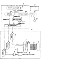
- FIG. 1 shows an essential part of an NC apparatus 50 and an NC machine tool 100 controlled by the NC apparatus 50 according to Embodiment 1 of the present invention.
- an NC apparatus 50 controls an NC machine tool 100 that is a machine tool to be controlled.
- the NC machine tool 100 includes a first drive unit 1, a second drive unit 2, a third drive unit 3, a servo motor 4, a first rotary shaft 5, a second rotary shaft 6, a tool 7, a pole screw 9, and a main shaft.
- a table 10 and a chuck 11 are provided.
- the workpiece 12 is fixed by the chuck 11.
- the first drive unit 1 rotates the first rotation shaft 5 that is the main shaft.
- the first rotating shaft 5 is held on the head stock 10.
- the second drive unit 2 rotates the second rotation shaft 6 on the first rotation shaft 5 to move the cutting tool 7 (cutting tool) in the radial direction (virtual X axis) of the workpiece 12. .
- the third drive unit 3 rotates the servo motor 4, and the servo motor 4 rotates the pole screw 9, thereby causing the spindle stock 10 and the first rotary shaft 5 on the spindle stock to move in the longitudinal direction of the workpiece 12. It moves on a straight line connecting a certain first rotating shaft 5 and the chuck 11.
- the tool 7 is not restricted to this.
- the NC device 50 includes a program analysis processing unit 51, an interpolation processing unit 52, a manual command processing unit 53, a movement distribution processing unit 54, and a servo communication processing unit 55.
- the program analysis processing unit 51 analyzes the machining program 60 for each block, and analyzes the movement amount in one block of each axis.
- the machining program 60 is a dedicated program for commands that the NC machine tool 100 should operate.
- a G code or m2 code as defined in JISB6315-2 may be used, but the present invention is not limited to this.
- One block of the machining program 60 is a code for one line in the machining program. Since the machining program 60 generally processes one line at a time by an interpreter method, this processing unit is set to “block”.
- the manual command processing unit 53 processes a manual movement command input from the operation panel 61 and the manual pulse generator 62.
- the interpolation processing unit 52 calculates the amount of movement (hereinafter referred to as FdT) that moves at the interpolation cycle for each axis based on the results calculated by the program analysis processing unit 51 and the manual command processing unit 53.
- the movement distribution processing unit 54 distributes the command for the virtual axis X of the workpiece 12 among the FdT calculated by the interpolation processing unit 52 to the movement amounts of the first rotary shaft 5 and the second rotary shaft 6.
- the servo communication processing unit 55 transmits FdT calculated by the interpolation processing unit 52 and the movement distribution processing unit 54 to the first drive unit 1, the second drive unit 2, and the third drive unit 3.
- the operation panel 61 and the manual pulse generator 62 were demonstrated as the outside of the numerical control apparatus 10, it is not restricted to this.
- the operation panel 61 and the manual pulse generator 62 may exist as part of the numerical controller 10.
- the machining program 60 includes a rotation speed command for operating the first rotating shaft 5 as a main axis, together with a movement command for other operation axes (Y axis and Z axis) other than the virtual X axis.
- a movement command for the virtual axis X is written.
- the program analysis processing unit 51 reads the machining program 60, analyzes the read machining program 60 for each block, and performs one block for each axis including the rotation speed of the first rotating shaft 5 that is the main axis and the virtual axis X. Calculate the amount of movement.
- the operation panel 61 incorporates an operation switch for the virtual axis X together with operation switches for the other operation axes. Further, a switch for assigning a manual pulse generated by the manual pulse generator 62 to the virtual axis X is incorporated.
- the manual command processing unit 53 calculates a manual movement command generated by a switch on the operation panel 61 or a manual pulse generator as an amount of movement for each axis including the virtual axis X.
- the interpolation processing unit 52 is activated at a fixed cycle (for example, 1 millisecond) called an interpolation cycle, and the movement amount calculated by the program analysis processing unit 51 in the case of the automatic operation and the manual command in the case of the manual operation.
- FdT is calculated for each axis including the virtual axis X according to a known interpolation method.
- the FdT distribution calculation method of the first rotating shaft 5 and the second rotating shaft 6 performed by the movement distributing unit 14 based on the FdT with respect to the virtual axis X out of the FdT calculated by the interpolation processing unit 52 will be described. To do. First, the conversion from the position command with respect to the virtual axis X to the rotation angle of the second rotation shaft 6 will be described with reference to FIG.
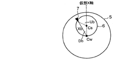
- FIG. 2 is a conceptual diagram viewed from the workpiece 12 side when the cutting tool 7 is at the outermost position of the machining diameter of the workpiece 12. This state is set as a reference position in the relationship between the first rotating shaft 5 and the second rotating shaft 6 and the virtual axis X.
- the position on the virtual axis X of the cutting tool 7 at this time is denoted as Xa.
- the rotation angle (D) of the first rotation axis which is the angle formed by the straight line connecting the cutting tool 7 and the first rotation axis center (Cw) and the virtual X axis, is treated as zero.
- the rotation angle (U) of the second rotation axis which is the angle formed by the straight line connecting the cutting tool 7 and the second rotation axis center (Cs), and the virtual X axis is treated as zero. 2 to 4, the center (Cw) of the first rotating shaft passes through the circumference of the second rotating shaft 6 to which the cutting tool 7 is fixed.
- the Z-axis is moved by a screw pitch (thread width) during one rotation of the main shaft (360 degrees).
- the first rotary shaft 5 operates once (360 degrees) between FIG. 2 and FIG. 3 in the processing of taper thread cutting (screws having a slanted diameter by changing the thread portion).
- the rotation angle of the first rotation shaft 5 becomes Db due to the rotation of the second rotation shaft 6 around the second rotation shaft center (Cs). That is, the position of the cutting tool 7 is inclined by Db from the virtual X axis.
- the cutting tool 7 is actually rotated by 360 degrees or more (360 degrees + Db) around the first rotation axis center (Cw), and the width of the screw thread becomes incorrect. For this reason, by correcting the position of the cutting tool 7 to the position shown in FIG. 4, it is necessary to perform taper threading with the position of the cutting tool 7 set to a 360-degree rotational position. That is, in FIG. 3, the cutting tool 7 needs to move (the cutting tool 7 moves on the virtual axis X axis) so that the rotation angle (Ub) of the second rotation axis becomes 0 degree.
- FIG. 4 is a conceptual diagram in a state where the position of the cutting tool 7 with respect to the first rotating shaft 5 is improved by the correction operation with respect to the first rotating shaft 5, that is, when the rotation angle of the second rotating shaft 6 is zero.
- the second rotary shaft 6 has the second rotary shaft angle Ub, that is, in synchronization with the movement of the cutting tool 7 to the Ub position, as shown in FIG.
- the position of the cutting tool 7 is corrected by moving the cutting tool 7 to a position of 360 degrees-Db.
- FIG. 3 is a tilted position as compared with FIG.
- FIG. 4 is a diagram in which this is corrected and corrected to a position that is not inclined as compared with FIG.
- the first rotating shaft 5 rotates 360 degrees
- the cutting tool 7 rotates (360 + Db) degrees. Therefore, in this NC machine tool 100, the cutting tool 7 is rotated 360 degrees by rotating the first rotating shaft 5 by (360-Db) degrees, and the process proceeds from FIG. 2 to FIG.
- the source of Db is accompanying the movement of the virtual axis X, and Db is generated depending on the amount of movement of the virtual axis X during the transition from FIG. 2 to FIG. 3 (FIG. 4).
- the rotation angle of the rotary shaft 5 is corrected.
- the cutting tool 7 faces an unintended direction as shown in FIG. 5, so that the cutting tool 7 is processed by processing on the NC machine tool 100 side to be controlled.
- the center of the first rotating shaft 5 is always directed.
- this series of control corresponds to FdT based on the rotational speed commanded to rotate the first rotating shaft 5 as the main shaft and FdT based on the correction of the position of the cutting tool 7 by the movement of the virtual axis X. To do.
- the servo communication unit 15 uses the servo communication unit 15 to calculate the FdT of the first rotation axis and the FdT of the second rotation axis calculated as described above in the movement distribution processing unit 54 and the FdT for the other axes calculated in the interpolation processing unit 52. This is transmitted to one drive unit 1, second drive unit 2, and third drive unit 3.
- FIG. 6 is a diagram showing a state in which taper-shaped threading is performed by the above-described series of controls.
- a screw having a constant pitch can be machined by one rotation of the main shaft while the shaft moving in the length direction of the workpiece moves the amount commanded by the screw pitch.
- the position of the cutting tool 7 with respect to the first rotating shaft 5 is rotated once while the axis of the workpiece 12 moving in the length direction moves the amount commanded by the screw pitch. Since it is possible to perform threading with a constant pitch, in the case of threading with a tapered shape, the correction amount for the first rotating shaft 5 is changed in synchronization with the movement of the workpiece 12 in the length direction. .
- the correction amount Cc with respect to the first rotation axis 5 when the position in the length direction of the workpiece is Zc
- the correction with respect to the first rotation axis 5 when the position in the length direction of the workpiece is Zd.
- the amount is Cd. Since the correction amount for the first rotation axis 5 is calculated every time the position of the virtual axis X changes in the interpolation processing unit 52, the movement in the length direction of the workpiece 12 calculated by the interpolation processing unit 52 is performed. It fluctuates synchronously.
- the numerical control device 50 and the numerically controlled machining system according to the present invention include a workpiece having a large machining diameter, a workpiece having a long length, a workpiece in which only a part has a cylindrical shape or a tapered shape, etc. It is suitable for use as an apparatus for controlling a machine tool for the purpose of processing a cylindrical shape or a tapered shape without rotating the workpiece.
- the present invention relates to a numerical control device (Numerical Controller) (hereinafter, NC device) and a numerical control work system.
- NC device numerical control device
- NC work system a numerical control work system
Landscapes
- Engineering & Computer Science (AREA)
- Human Computer Interaction (AREA)
- Manufacturing & Machinery (AREA)
- Physics & Mathematics (AREA)
- General Physics & Mathematics (AREA)
- Automation & Control Theory (AREA)
- Mechanical Engineering (AREA)
- Numerical Control (AREA)
- Turning (AREA)
Abstract
Priority Applications (4)
| Application Number | Priority Date | Filing Date | Title |
|---|---|---|---|
| DE112009004909T DE112009004909T5 (de) | 2009-06-10 | 2009-06-10 | Numerische Steuervorrichtung und numerisch gesteuertes Bearbeitungssystem |
| US13/320,869 US20120065768A1 (en) | 2009-06-10 | 2009-06-10 | Numerical controller and numerical control machining system |
| PCT/JP2009/002603 WO2010143227A1 (fr) | 2009-06-10 | 2009-06-10 | Dispositif de commande numérique et système d'usinage à commande numérique |
| JP2011518074A JP5287986B2 (ja) | 2009-06-10 | 2009-06-10 | 数値制御装置及び数値制御工作システム |
Applications Claiming Priority (1)
| Application Number | Priority Date | Filing Date | Title |
|---|---|---|---|
| PCT/JP2009/002603 WO2010143227A1 (fr) | 2009-06-10 | 2009-06-10 | Dispositif de commande numérique et système d'usinage à commande numérique |
Publications (1)
| Publication Number | Publication Date |
|---|---|
| WO2010143227A1 true WO2010143227A1 (fr) | 2010-12-16 |
Family
ID=43308500
Family Applications (1)
| Application Number | Title | Priority Date | Filing Date |
|---|---|---|---|
| PCT/JP2009/002603 Ceased WO2010143227A1 (fr) | 2009-06-10 | 2009-06-10 | Dispositif de commande numérique et système d'usinage à commande numérique |
Country Status (4)
| Country | Link |
|---|---|
| US (1) | US20120065768A1 (fr) |
| JP (1) | JP5287986B2 (fr) |
| DE (1) | DE112009004909T5 (fr) |
| WO (1) | WO2010143227A1 (fr) |
Cited By (1)
| Publication number | Priority date | Publication date | Assignee | Title |
|---|---|---|---|---|
| JP6719684B1 (ja) * | 2019-04-11 | 2020-07-08 | 三菱電機株式会社 | 数値制御装置 |
Families Citing this family (7)
| Publication number | Priority date | Publication date | Assignee | Title |
|---|---|---|---|---|
| JP4351281B2 (ja) * | 2007-12-13 | 2009-10-28 | ファナック株式会社 | 5軸加工機を制御する数値制御装置 |
| WO2013038529A1 (fr) * | 2011-09-14 | 2013-03-21 | 株式会社ジェイテクト | Dispositif de calcul d'erreur d'usinage, procédé de calcul d'erreur d'usinage, dispositif de commande d'usinage et procédé de commande d'usinage |
| JP5624163B2 (ja) * | 2013-01-17 | 2014-11-12 | ファナック株式会社 | ねじ切りサイクルの再加工を行う機能を有する数値制御装置 |
| EP2862653B1 (fr) * | 2013-10-15 | 2017-09-13 | Korea Institute Of Machinery & Materials | Appareil d'usinage pour tournage |
| JP5883535B1 (ja) * | 2015-10-02 | 2016-03-15 | 株式会社松浦機械製作所 | ワークの内周面又は外周面に対する切削方法 |
| JP6396346B2 (ja) | 2016-01-15 | 2018-09-26 | ファナック株式会社 | タレット回転による切込み制御機能を有する数値制御装置 |
| JP7177905B1 (ja) * | 2021-12-22 | 2022-11-24 | Dmg森精機株式会社 | 情報処理装置 |
Citations (4)
| Publication number | Priority date | Publication date | Assignee | Title |
|---|---|---|---|---|
| JPH08126938A (ja) * | 1994-09-05 | 1996-05-21 | Toshiba Mach Co Ltd | バイト工具による主軸回転角制御式切削加工方法 |
| JP2000015542A (ja) * | 1998-07-02 | 2000-01-18 | Toshiba Mach Co Ltd | 数値制御工作機械 |
| JP2005212036A (ja) * | 2004-01-29 | 2005-08-11 | Kazuyuki Hirano | 切削工具 |
| JP2007090489A (ja) * | 2005-09-29 | 2007-04-12 | Olympus Corp | 金型の切削加工方法及び装置 |
Family Cites Families (11)
| Publication number | Priority date | Publication date | Assignee | Title |
|---|---|---|---|---|
| JPS59151603U (ja) * | 1983-03-31 | 1984-10-11 | 株式会社小松製作所 | 工具径可変形主軸装置における工具 |
| JPS59201709A (ja) * | 1983-04-28 | 1984-11-15 | Komatsu Ltd | 工具径可変形主軸装置における加工方法 |
| JPS6029010U (ja) * | 1983-07-29 | 1985-02-27 | 株式会社小松製作所 | 工具径可変形主軸装置における制御装置 |
| JPH0628840B2 (ja) * | 1984-03-12 | 1994-04-20 | 株式会社小松製作所 | 工具径可変形主軸装置における内側主軸の回転角制御方法 |
| JPH074684B2 (ja) * | 1985-11-30 | 1995-01-25 | 三井精機工業株式会社 | 切込量調整可能な2重主軸構造 |
| JPS63180403A (ja) * | 1987-01-23 | 1988-07-25 | Hitachi Seiko Ltd | 偏心クイルボ−リング装置 |
| JPH0533201Y2 (fr) * | 1987-09-30 | 1993-08-24 | ||
| JP2736359B2 (ja) * | 1992-01-10 | 1998-04-02 | オークマ株式会社 | カム切削旋盤の刃物台 |
| JP2996804B2 (ja) * | 1992-04-30 | 2000-01-11 | オークマ株式会社 | 偏心形状加工装置 |
| TW301619B (fr) * | 1994-10-07 | 1997-04-01 | Toshiba Machine Co Ltd | |
| JP4446003B2 (ja) * | 2008-02-18 | 2010-04-07 | 株式会社三共製作所 | 切削加工ユニット、及び工作機械 |
-
2009
- 2009-06-10 WO PCT/JP2009/002603 patent/WO2010143227A1/fr not_active Ceased
- 2009-06-10 US US13/320,869 patent/US20120065768A1/en not_active Abandoned
- 2009-06-10 JP JP2011518074A patent/JP5287986B2/ja active Active
- 2009-06-10 DE DE112009004909T patent/DE112009004909T5/de not_active Withdrawn
Patent Citations (4)
| Publication number | Priority date | Publication date | Assignee | Title |
|---|---|---|---|---|
| JPH08126938A (ja) * | 1994-09-05 | 1996-05-21 | Toshiba Mach Co Ltd | バイト工具による主軸回転角制御式切削加工方法 |
| JP2000015542A (ja) * | 1998-07-02 | 2000-01-18 | Toshiba Mach Co Ltd | 数値制御工作機械 |
| JP2005212036A (ja) * | 2004-01-29 | 2005-08-11 | Kazuyuki Hirano | 切削工具 |
| JP2007090489A (ja) * | 2005-09-29 | 2007-04-12 | Olympus Corp | 金型の切削加工方法及び装置 |
Cited By (3)
| Publication number | Priority date | Publication date | Assignee | Title |
|---|---|---|---|---|
| JP6719684B1 (ja) * | 2019-04-11 | 2020-07-08 | 三菱電機株式会社 | 数値制御装置 |
| WO2020208783A1 (fr) * | 2019-04-11 | 2020-10-15 | 三菱電機株式会社 | Dispositif de commande numérique |
| CN113711143A (zh) * | 2019-04-11 | 2021-11-26 | 三菱电机株式会社 | 数控装置 |
Also Published As
| Publication number | Publication date |
|---|---|
| JPWO2010143227A1 (ja) | 2012-11-22 |
| JP5287986B2 (ja) | 2013-09-11 |
| US20120065768A1 (en) | 2012-03-15 |
| DE112009004909T5 (de) | 2012-06-21 |
Similar Documents
| Publication | Publication Date | Title |
|---|---|---|
| JP5287986B2 (ja) | 数値制御装置及び数値制御工作システム | |
| CN108732989B (zh) | 进行摆动切削的机床的控制装置 | |
| CN110695762B (zh) | 机床的控制装置 | |
| US10471563B2 (en) | Control device for machine tool performing oscillation cutting | |
| JP5293389B2 (ja) | 工作機械の制御装置 | |
| JP6175269B2 (ja) | 多軸フライス加工 | |
| JP2018180633A (ja) | 揺動切削を行う工作機械の制御装置 | |
| JP2017056515A (ja) | 複数軸を備えた工作機械の制御装置 | |
| JP5240412B1 (ja) | 数値制御装置 | |
| JP3603051B2 (ja) | 数値制御工作機械の送り速度・加速度制御方法および数値制御装置 | |
| US10016815B2 (en) | Machine tool and machining method | |
| JP2011044081A (ja) | 工作機械の制御装置 | |
| WO2010103672A1 (fr) | Procédé de commande de rotation de broche principale et dispositif de commande de machine-outil | |
| WO2022264260A1 (fr) | Dispositif de traitement d'informations, dispositif de commande de machine-outil et programme informatique | |
| US9886021B2 (en) | Control device for coordinating translation and revolution movement in a machine tool | |
| JP2018043306A (ja) | 工作機械およびその制御装置 | |
| JP2013121627A (ja) | 回転軸を備えたワイヤ放電加工機 | |
| TWI768194B (zh) | 工作機械 | |
| WO2002027417A1 (fr) | Dispositif de commande numerique et methode correspondante | |
| US10486240B2 (en) | Numerical controller having cutting control function through turret rotation | |
| JP2018120643A (ja) | 複数軸を備えた工作機械の制御装置 | |
| US11507050B2 (en) | Milling method | |
| JP6865413B2 (ja) | Nc旋盤及びこれを用いた切削加工方法 | |
| WO2023139743A1 (fr) | Dispositif de traitement d'informations, dispositif de commande de machine-outil, et programme informatique | |
| JP3490962B2 (ja) | 工具軌跡作成方法及び加工方法 |
Legal Events
| Date | Code | Title | Description |
|---|---|---|---|
| 121 | Ep: the epo has been informed by wipo that ep was designated in this application |
Ref document number: 09845753 Country of ref document: EP Kind code of ref document: A1 |
|
| WWE | Wipo information: entry into national phase |
Ref document number: 2011518074 Country of ref document: JP |
|
| WWE | Wipo information: entry into national phase |
Ref document number: 13320869 Country of ref document: US |
|
| WWE | Wipo information: entry into national phase |
Ref document number: 1120090049095 Country of ref document: DE Ref document number: 112009004909 Country of ref document: DE |
|
| 122 | Ep: pct application non-entry in european phase |
Ref document number: 09845753 Country of ref document: EP Kind code of ref document: A1 |