WO2010143349A1 - 無線内視鏡装置およびその受信装置、ならびに受信方法 - Google Patents
無線内視鏡装置およびその受信装置、ならびに受信方法 Download PDFInfo
- Publication number
- WO2010143349A1 WO2010143349A1 PCT/JP2010/002821 JP2010002821W WO2010143349A1 WO 2010143349 A1 WO2010143349 A1 WO 2010143349A1 JP 2010002821 W JP2010002821 W JP 2010002821W WO 2010143349 A1 WO2010143349 A1 WO 2010143349A1
- Authority
- WO
- WIPO (PCT)
- Prior art keywords
- communication channel
- communication
- channel group
- belonging
- wireless
- Prior art date
- Legal status (The legal status is an assumption and is not a legal conclusion. Google has not performed a legal analysis and makes no representation as to the accuracy of the status listed.)
- Ceased
Links
Images


Classifications
-
- A—HUMAN NECESSITIES
- A61—MEDICAL OR VETERINARY SCIENCE; HYGIENE
- A61B—DIAGNOSIS; SURGERY; IDENTIFICATION
- A61B1/00—Instruments for performing medical examinations of the interior of cavities or tubes of the body by visual or photographical inspection, e.g. endoscopes; Illuminating arrangements therefor
- A61B1/00002—Operational features of endoscopes
- A61B1/00011—Operational features of endoscopes characterised by signal transmission
- A61B1/00016—Operational features of endoscopes characterised by signal transmission using wireless means
-
- H—ELECTRICITY
- H04—ELECTRIC COMMUNICATION TECHNIQUE
- H04N—PICTORIAL COMMUNICATION, e.g. TELEVISION
- H04N7/00—Television systems
- H04N7/18—Closed-circuit television [CCTV] systems, i.e. systems in which the video signal is not broadcast
- H04N7/183—Closed-circuit television [CCTV] systems, i.e. systems in which the video signal is not broadcast for receiving images from a single remote source
- H04N7/185—Closed-circuit television [CCTV] systems, i.e. systems in which the video signal is not broadcast for receiving images from a single remote source from a mobile camera, e.g. for remote control
-
- H—ELECTRICITY
- H04—ELECTRIC COMMUNICATION TECHNIQUE
- H04W—WIRELESS COMMUNICATION NETWORKS
- H04W72/00—Local resource management
- H04W72/50—Allocation or scheduling criteria for wireless resources
- H04W72/54—Allocation or scheduling criteria for wireless resources based on quality criteria
- H04W72/542—Allocation or scheduling criteria for wireless resources based on quality criteria using measured or perceived quality
Definitions
- the present invention relates to a wireless endoscope apparatus, a receiving apparatus therefor, and a receiving method.
- an endoscope apparatus capable of observing a subject image in a body cavity or duct by a monitor by inserting an elongated insertion portion into the body cavity or duct.
- Such an endoscope apparatus generally includes an endoscope having an insertion portion inserted into a body cavity or a duct, and a main body apparatus having a light source device and a video processor, and the endoscope and the main body apparatus Is connected by a light guide cable for guiding illumination light from the light source device to the endoscope, and a signal cable for transmitting an imaging signal obtained by the endoscope to the video processor.
- a light guide cable for guiding illumination light from the light source device to the endoscope
- a signal cable for transmitting an imaging signal obtained by the endoscope to the video processor.
- the light guide cable extended from the endoscope is removed by the illuminating device comprised with LED (light emitting diode) etc. being incorporated in an endoscope.
- the endoscope is provided with a video signal processing circuit for obtaining a video signal which can be displayed on a monitor by performing video signal processing on an imaging signal, and a transmission circuit for transmitting the video signal by radio waves.
- a receiver for demodulating the video signal separately from the endoscope the signal cable extending from the endoscope is removed.
- such an endoscope apparatus is also referred to as a wireless endoscope apparatus, and has the advantage that the restriction on the movement range of the endoscope is alleviated and the operability is improved.
- the receiving device since the receiving device is provided separately from the endoscope, the communication channel of the transmitting endoscope is set according to the communication channel set in the receiving device, It is necessary to connect by wireless communication.
- a method of uniquely determining the combination of the receiving apparatus and the endoscope and setting the communication channel in advance to an arbitrary channel in a fixed manner There is also conceivable a method of uniquely determining the combination of the receiving apparatus and the endoscope and setting the communication channel in advance to an arbitrary channel in a fixed manner.
- the combination of the receiving device and the endoscope can not be uniquely determined because the sterilization and sterilization treatment of the endoscope and the examination are simultaneously advanced. .
- the communication channels of the receiving apparatus need to be set differently.
- each of the receiving device and the endoscope is provided with a selection switch for the communication channel, and the same communication channel as the communication channel set in the receiving device to be used at the start of use of the endoscope device is used.
- the same communication channel as the communication channel set in the receiving device to be used at the start of use of the endoscope device is used.
- a wireless terminal In data communication performed by a general personal computer via a wireless LAN, after searching for all available communication channels and detecting a connectable wireless terminal (AP), the user selects a wireless terminal (AP) to be connected
- the connection to the wireless LAN is implemented by the following method. Also, in recent years, at home wireless LAN access points, when the power is turned on, all communication channels available in the wireless LAN are searched, and vacant communication channels not used by other wireless terminals are detected and vacant.
- a function of automatically setting a communication channel from the communication channel of As described above, in a wireless LAN in a general personal computer, after searching for all available communication channels, the communication channel to be connected is determined, so it takes time to connect.
- the present invention has been made in view of the above problems, and an object of the present invention is to provide a wireless endoscope apparatus capable of efficiently selecting a communication channel in a good communication state, a receiving apparatus therefor, and a receiving method. I assume.
- the receiving device of the wireless endoscope apparatus has been made to solve the above-mentioned problems, and has n (n> 1) in which the use frequency band partially overlaps at least one other communication channel.
- a determination unit configured to detect a use status of a communication channel to which the communication channel belongs, and to determine whether to perform communication using a communication channel belonging to the selected communication channel group based on a result of the detection.
- the receiving device of the wireless endoscope apparatus is an output unit that outputs information prompting selection of a communication channel group different from the selected communication channel group when the determining unit determines not to perform the communication. May further be included.
- the output unit may output information on a use state of a communication channel for performing the communication when the determining unit determines that the communication is to be performed.
- the receiving device of the wireless endoscope apparatus may further include an operation unit that causes the operator to select a communication channel group and transmits the result of the selection to the determination unit.
- the determination unit may detect, as the use status, a communication amount of a communication channel belonging to the selected communication channel group.
- the determination unit may detect, as the use status, received signal strength of a communication channel belonging to the selected communication channel group.
- the determination unit uses a communication channel belonging to the selected communication channel group based on the presence of the communication channel whose communication amount falls below a predetermined threshold. It may be determined whether or not to perform the communication.
- the determining unit determines a communication channel belonging to the selected communication channel group based on the presence of the communication channel whose received signal strength falls below a predetermined threshold. It may be determined whether or not to use the communication used.
- the determining unit performs communication using a communication channel belonging to a communication channel group in which the total communication amount of communication channels belonging to the same communication channel group is the smallest. You may decide.
- the storage unit may store a communication channel group to which a communication channel whose frequency band does not overlap with a specific communication channel belonging to another communication channel group belongs.
- the storage unit is a communication channel group to which a communication channel having a use frequency band overlapping with a specific communication channel belonging to the same communication channel group exceeds a predetermined range. May be stored.
- the reception device of the radio endoscope apparatus has L (1 ⁇ L) among n (n> 1) communication channels in which the use frequency band partially overlaps with at least one other communication channel.
- ⁇ N) selecting an arbitrary communication channel group from x (1 ⁇ x ⁇ n) communication channel groups to which the communication channels belong, and the use status of the communication channels belonging to the selected communication channel group And detecting whether to perform communication using a communication channel belonging to the selected communication channel group based on the result of the detection; and belonging to the selected communication channel group
- the communication channel is used to communicate with the transmitting device, and the image data transmitted from the transmitting device is received; To run.
- the wireless endoscope apparatus of the present invention is a wireless endoscope apparatus having a receiving device and a transmitting device, and the receiving device has n (n > 1) A first communication unit that communicates with the transmission device using a communication channel selected from among the communication channels and receives image data transmitted from the transmission device, L (1 ⁇ L ⁇ N) A storage unit for storing x (1 ⁇ x ⁇ n) communication channel groups to which the communication channels belong, and an arbitrary communication channel group selected from the communication channel groups stored by the storage unit Detecting the use state of the communication channel belonging to the selected communication channel group, and based on the result of the detection, determining whether to perform communication using the communication channel belonging to the selected communication channel group A transmitting unit that communicates with the receiving apparatus using a communication channel selected from among n communication channels, and transmits the image data to the receiving apparatus;
- the usage status of the communication channel belonging to the selected communication channel group is detected, and based on the result of the detection, it is determined whether to perform communication using the communication channel belonging to the selected communication channel group.
- FIG. 1 is an external view of an endoscope according to an embodiment of the present invention. It is a block diagram showing composition of an endoscope by one embodiment of the present invention. It is a block diagram showing composition of a receiver by one embodiment of the present invention.
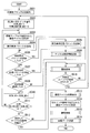
- 5 is a flowchart illustrating the operation of a receiving device according to an embodiment of the present invention. 5 is a flowchart illustrating the operation of a receiving device according to an embodiment of the present invention. 5 is a flowchart illustrating the operation of a logical connection according to an embodiment of the present invention. 5 is a flow chart showing the operation of the endoscope according to an embodiment of the present invention.
- 5 is a flowchart illustrating the operation of a receiving device according to an embodiment of the present invention.
- 5 is a flowchart illustrating the operation of a receiving device according to an embodiment of the present invention.
- 5 is a flowchart illustrating the operation of a receiving device according to an embodiment of the present invention.
- It is a reference drawing showing the contents of the communication channel setting table in one embodiment of the present invention.
- It is a reference drawing showing the contents of the search table in one embodiment of the present invention.
- It is a reference drawing showing the contents of the communication channel setting table in one embodiment of the present invention.
- It is a reference drawing showing the contents of the search table in one embodiment of the present invention.
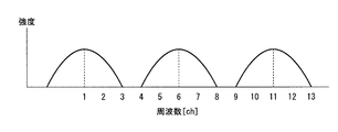
- It is a reference drawing showing the frequency band which a communication channel uses.
- It is a reference drawing showing the frequency band which a communication channel uses.
- It is a reference drawing showing the frequency band which a communication channel uses.
- wireless communication As a communication method used for wireless communication, it is effective to use a wireless communication method such as IEEE 802.11 used in a wireless LAN capable of high-speed data communication.
- wireless communication can be performed by selecting an arbitrary communication channel from a plurality of communication channels in order to use the frequency band effectively.
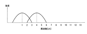
- Each communication channel is arranged so that a part of the frequency band to be used overlaps with another communication channel as shown in FIG. 16 due to the limitation of the available frequency band.
- processing of avoiding collision between transmission frames is performed under control of the IEEE 802.11 protocol.
- the endoscope apparatus can not recognize the transmission frame of the adjacent communication channel, and the transmission frame of the adjacent communication channel is transmitted. Processing to avoid collision does not work.
- the receiving apparatus can not normally receive the image data transmitted from the endoscope, and the image is interrupted.
- a certain amount of data communication delay is allowed, so the occurrence of a communication error does not become a major problem when data arrival is guaranteed by retransmission.
- efficient allocation of communication channels is required rather than avoiding the occurrence of communication errors due to temporary frame collisions, and the communication channel used is another wireless terminal. The communication channel to be used is determined based only on whether it is used or not used.
- the endoscope apparatus in order to ensure operability, it is important to transmit and receive all image data to be communicated without delay without delay, and select a communication channel with a good wireless environment It is essential to perform wireless communication at a low communication error rate. Therefore, the occurrence of a communication error due to a frame collision with a communication channel adjacent to the communication channel used by the endoscope device becomes a problem.
- the endoscope apparatus (wireless endoscope apparatus) according to the present embodiment can efficiently select a communication channel in a good communication state, achieve power saving, and reduce the occurrence of communication errors.
- IEEE 802.11 is used as an example of the wireless communication method.
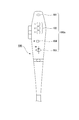
- FIG. 1 shows the configuration of the endoscope apparatus according to the present embodiment.
- the endoscope apparatus includes an endoscope 100 that transmits captured image data by wireless communication, and a receiving device 200 that receives the image data transmitted from the endoscope 100 and displays an image on a monitor. ing.
- the endoscope 100 includes an operation unit 100a including a plurality of switches for the operator to input an operation instruction.
- the receiving device 200 includes a communication setting display unit 201 including a plurality of LEDs indicating the communication setting state of the receiving device 200. Further, although not shown in FIG. 1, a CH (channel) setting switch is mounted on the back of the receiving device 200.
- FIG. 2 shows the endoscope 100 as viewed from the arrangement surface of the operation switch.
- the operation unit 100 a of the endoscope 100 includes a power switch 101, a plurality of operation switches 102, a CH setting switch 103, and a status display LED 104.
- the CH setting switch 103 has a number for identifying a setting channel.
- FIG. 3 shows the electrical configuration of the endoscope 100.
- the endoscope 100 includes a control unit 301, a ROM 302, a RAM 303, an imaging unit 304, an illumination unit 305, a wireless communication circuit unit 306, an antenna 307, an operation unit 308, and a power supply circuit unit 309.
- the control unit 301 operates in accordance with a program stored in the ROM 302 and controls the operation sequence of the endoscope 100.
- the ROM 302 is a non-volatile memory such as a Flash ROM, and stores various setting information including program data for controlling the endoscope 100 and communication setting parameters in the ROM 302.
- the communication setting parameters include a communication channel (frequency), an SSID (Service Set Identifier), a Wired Equivalent Privacy (WEP) and the like corresponding to each number added to the CH setting switch 103.
- a RAM 303 is used as a buffer for temporarily buffering image data output from the imaging unit 304, a work area used for operations of the control unit 301, and an area for temporarily storing various settings.
- the imaging unit 304 includes a lens that forms incident light, a photoelectric converter (such as a CCD or CMOS sensor) that converts the formed light into an electric signal, and a digital electric signal that is an analog electric signal output from the photoelectric converter. It consists of an AD converter (analog-digital converter) etc. to convert.
- a photoelectric converter such as a CCD or CMOS sensor
- AD converter analog-digital converter
- the illumination unit 305 includes an illumination lens, an LED, an LED drive circuit, and the like, and is disposed at the distal end 100 b (FIG. 1) of the endoscope 100.
- the light emitted from the LED is irradiated to the object in the body cavity through the irradiation lens.
- the LED may be disposed inside the operation unit 100a instead of the tip portion 100b, and light may be guided to the tip portion 100b by a light guide.
- the wireless communication circuit unit 306 includes a high frequency circuit unit necessary for wireless communication, an encoding / decoding circuit unit, a buffer memory and the like, and an antenna 307 is connected.
- the channel set in the receiving device 200 is used to set the communication channel set in the receiving device 200, the same communication channel as the SSID, etc., and the SSID, etc. It is necessary to set the CH setting switch 103 to the same number as the setting switch number. Further, communication setting parameters corresponding to the communication channel designated by each number of the CH setting switch 103 are set in the wireless communication circuit unit 306.
- the operation unit 308 (corresponding to the operation unit 100a in FIG. 1) has the power switch 101, the operation switch 102, and the CH setting switch 103 shown in FIG. 2, and outputs the button and the switch state and state change as electric signals. Do. Further, in the operation unit 308, a state display LED 104 for notifying of a connection state with the receiving device 200 is disposed.
- the power supply circuit unit 309 includes a battery, a DC / DC converter, and the like, detects that the power supply switch 101 is turned on, and supplies power to the above-described blocks.
- FIG. 4 shows the electrical configuration of the receiving device 200.
- the receiving apparatus 200 includes a control unit 401, a ROM 402, a RAM 403, a wireless communication circuit unit 404, an antenna 405, an image signal processing unit 406, a monitor 407, and an operation unit 408.
- the control unit 401 operates in accordance with a program stored in the ROM 402 and controls the operation sequence of the receiving device 200.
- the ROM 402 is a non-volatile memory such as a Flash ROM, and the program data for controlling the reception apparatus 200, various setting information including communication setting parameters, a communication channel setting table, and a search table are stored in the ROM 402.
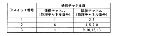
- FIG. 12 shows the contents of the communication channel setting table.
- communication channel numbers are associated with the numbers (CH switch numbers) of the CH setting switches.
- IEEE 802.11 wireless communication can be performed by selecting an arbitrary communication channel from a plurality of communication channels. Although the center frequency of each communication channel is 5 MHz apart, since each communication channel uses a frequency band of about 20 MHz, overlapping of frequency bands to be used occurs between adjacent communication channels as shown in FIG. Do.
- thirteen communication channels are prepared, and these thirteen communication channels belong to at least one of the three communication channel groups corresponding to each CH switch number.
- a communication channel group consisting of communication channels 1, 2, 3 and 4 corresponds to CH switch No. 1
- CH switch No. 2 corresponds to communication channels 3, 4, 5, 6, 7, 8, 9
- the corresponding communication channel group corresponds, and to the CH switch number 3, the communication channel group consisting of the communication channels 8, 9, 10, 11, 12, 13 corresponds.
- One communication channel among the communication channels belonging to each communication channel group is used for the logical connection described later. For example, if CH switch number 1 is set, communication channel 1 is used for logical connection, and if CH switch number 2 is set, communication channel 6 is used for logical connection and CH switch number 3 is set In this case, communication channel 11 is used for the logical connection.
- These communication channels 1, 6, 11 are the same as the communication channels set by the CH setting switch 103 in the endoscope 100. As shown in FIG. 17, the frequency bands of the communication channels 1, 6, 11 do not overlap.
- One communication channel group includes one communication channel (denoted as communication channel in FIG. 12) used for logical connection and a communication channel in which this communication channel and the used frequency band partially overlap (denoted as adjacent channels in FIG. 12). And).
- n (n> 1) communication channels in which the use frequency band partially overlaps with at least one other communication channel are prepared, and L (1 ⁇ L ⁇ n) communication channels are provided.
- FIG. 13 shows the contents of the search table.
- the search table the number of communication channels belonging to each communication channel is associated with each CH switch number along with the search order.
- the search phase the use status of the communication channel is detected in the order according to the search order.
- the RAM 403 is a buffer for temporarily buffering the image data received by the wireless communication circuit unit 404, a work area used for calculation of the control unit 401, various settings, etc. Used as a temporary storage area.
- the wireless communication circuit unit 404 includes a high frequency circuit unit necessary for wireless communication, an encoding / decoding circuit unit, a buffer memory and the like, and an antenna 405 is connected. Like the wireless communication circuit unit 306 of the endoscope 100, the wireless communication circuit unit 404 performs wireless communication in accordance with a wireless LAN protocol.
- the communication channel designated by the CH switch number set by the CH setting switch is read out from the communication channel setting table of FIG. 12, and the communication setting parameter corresponding to the communication channel is set in the wireless communication circuit unit 404.
- the image signal processing unit 406 converts the image data received by the wireless communication circuit unit 404 into an NTSC signal or a PAL signal, and outputs the signal to the monitor 407.
- the monitor 407 is configured of a liquid crystal display device and its control circuit, and displays an image and operates as a notification unit that notifies of the state of wireless connection.
- the operation unit 408 has a CH setting switch mounted on the back of the receiving apparatus 200, and outputs the state and the state change of the CH setting switch as an electric signal. Further, in the operation unit 408, a communication setting display unit 201 (FIG. 1) for displaying the communication channel selected by the CH setting switch with an LED is disposed.
- the operator sets the communication channel using the CH setting switch of the receiving device 200, and then turns on the power of the receiving device 200.
- the control unit 401 initializes each functional block of the receiving apparatus 200 (step S501). At this time, in order to indicate the communication setting set by the CH setting switch of the receiving device 200, among the LEDs of the communication setting display unit 201, the LED corresponding to the set communication channel is turned on.
- the control unit 401 initializes parameters (SW_NO, SCAN_NO, TERM_NUM [SW_NO]) to be used for subsequent control (step S502).
- SW_NO is a parameter for storing a CH switch number, and at initialization, the CH switch number set by the CH setting switch is stored.
- SCAN_NO is a parameter for storing the search order in the search table, and 1 is stored at the time of initialization.
- TERM_NUM [SW_NO] is a parameter for storing the number of surrounding wireless communication terminals using a communication channel that satisfies a predetermined condition, and 0 is stored at initialization. There are three values of TERM_NUM [SW_NO]: TERM_NUM [1], TERM_NUM [2], and TERM_NUM [3].
- the receiving device 200 performs physical connection of wireless communication on the communication channel selected by the operator as follows.
- a radio frequency and an SSID to be used in connection in the physical layer are determined, and a packet to be transmitted to or received from a communication partner can be captured on hardware.
- the receiving device 200 shifts to a communication channel search phase.
- the control unit 401 reads out from the search table the number of the communication channel (the communication channel whose CH switch number is SW_NO and the search order is SCAN_NO) specified by SW_NO and SCAN_NO, and the communication corresponding to that communication channel
- the setting parameter is read out from the ROM 402 and set in the wireless communication circuit unit 404 (step S503).
- searching for a communication channel a search request packet is transmitted, and reception of a search request response packet for the search request packet is performed for a predetermined period.
- the control unit 401 causes the wireless communication circuit unit 404 to transmit a search request packet by broadcast (step S504).
- the communication terminal in which the same communication channel as the receiving device 200 is set receives the search request packet transmitted from the receiving device 200, and transmits the search request response packet.
- the control unit 401 determines whether a search request packet from another wireless communication terminal has been received (step S505). When the search request packet is received, the control unit 401 causes the wireless communication circuit unit 404 to transmit the search request response packet by unicast (step S506). Thereafter, the process returns to step S505. If the search request packet has not been received, the control unit 401 determines whether a search request response packet from another wireless communication terminal has been received (step S507). When the search request response packet is received, the control unit 401 executes a process of updating the value of TERM_NUM [SW_NO] (channel search information) (step S508). Thereafter, the process returns to step S505. If the search request response packet has not been received, the process proceeds to step S509.
- FIG. 6 shows the details of step S508.
- the control unit 401 determines whether the value of SCAN_NO is 1 (step S508a). If the value of SCAN_NO is 1, processing proceeds to step S508c. If the value of SCAN_NO is not 1, the control unit 401 determines whether the reception level (received signal strength) of the frame of the search request response packet is equal to or higher than a predetermined level (step S508 b). If the frame reception level is equal to or higher than the predetermined level, the process proceeds to step S508c. If the frame reception level is less than the predetermined level, the process returns to step S505.
- step S508c the control unit 401 adds 1 to the value of TERM_NUM [SW_NO] to update the value (step S508c). After the process of step S508 c, the process proceeds to step S509.
- the value of TERM_NUM [SW_NO] is the same communication channel as the communication channel (one of communication channels 1, 6 and 11) set by the CH setting switch, or the communication channel set by the CH setting switch And the number of surrounding wireless communication terminals using communication channels whose use frequency bands overlap.
- step S508a when the value of SCAN_NO is 1, another wireless communication terminal uses the same communication channel as the communication channel set by the CH setting switch.
- step S508b when the reception level of the frame is equal to or higher than the predetermined level, another wireless communication terminal uses a communication channel in which the communication channel set by the CH setting switch and the used frequency band overlap.
- a common threshold is set as the threshold of the reception level of the frame in each adjacent channel, but a threshold of a predetermined reception level may be set for each adjacent channel.
- step S509 the control unit 401 determines whether a predetermined time has elapsed since the search request packet was transmitted in step S504 (step S509). If the predetermined time has not elapsed, the process returns to step S505. Also, when the predetermined time has elapsed, the control unit 401 adds 1 to the value of SCAN_NO, and updates the value (step S510).
- the control unit 401 reads out from the search table the number of the communication channel (the communication channel whose CH switch number is SW_NO and the search order is SCAN_NO) specified by SW_NO and SCAN_NO after update from the search table. It is determined whether or not it is (step S511). If the communication channel number designated by SW_NO and SCAN_NO after update is not 0, the process returns to step S503. If the communication channel number specified by SW_NO and SCAN_NO after update is 0, the control unit 401 determines whether the communication channel set by the CH setting switch is usable (step S512).
- the control unit 401 determines that the communication channel set by the CH setting switch is available when the number of wireless terminals (TERM_NUM [SW_NO]) collected in step S508 is less than a predetermined threshold. to decide. If it is determined that the communication channel set by the CH setting switch is usable, the control unit 401 causes the monitor 407 to display the usage status of the communication channel set by the CH setting switch (step S513). At this time, the number of wireless communication terminals using each communication channel included in the communication channel group may be displayed numerically, or the congestion degree of the communication channel may be graphically displayed based on a preset threshold value. It is also good.
- control unit 401 reads out the number of the communication channel (one of communication channels 1, 6 and 11) set by the CH setting switch from the communication channel setting table, and the communication setting parameter corresponding to the communication channel is read from the ROM 402. , And are set in the wireless communication circuit unit 404 (step S514).
- the receiving apparatus 200 proceeds to the logical connection phase, and executes a process of establishing a logical connection (step S515).
- the endoscope 100 transmits a MAC address request packet including the MAC address of the endoscope 100, and the receiving device 200 having received the MAC address request packet receives the MAC address including the MAC address of the receiving device 200.
- the MAC address is exchanged between the endoscope 100 and the receiving device 200.
- FIG. 7 shows the details of step S515 shown in FIG.
- the control unit 401 determines whether a search request packet from another wireless communication terminal has been received (step S515a). When the search request packet is received, the control unit 401 causes the wireless communication circuit unit 404 to transmit the search request response packet by unicast (step S515b). Thereafter, the process returns to step S515a. If the search request packet has not been received, the control unit 401 determines whether a MAC address request packet from another wireless communication terminal has been received (step S515c).
- control unit 401 causes the wireless communication circuit unit 404 to transmit the MAC address request response packet by unicast (step S515 d). On the other hand, if the MAC address request packet has not been received, the process returns to step S515a.
- the wireless communication circuit unit 404 starts to receive the image data transmitted from the endoscope 100 (step S516).
- step S512 If it is determined in step S512 that the communication channel set by the CH setting switch is not usable, the control unit 401 reports that the communication environment of the communication channel set by the CH setting switch is not good and can not be used.
- a warning message instructing change of the CH setting switch is displayed on the monitor 407 (step S517). For example, a message “The set communication channel can not be used, change the CH setting switch” is displayed on the monitor 407.
- control unit 401 determines whether the state of the CH setting switch has been changed (step S518). If the state of the CH setting switch has not been changed, the process of step S517 is performed again. If the state of the CH setting switch has been changed, the process returns to step S502 again.
- the operator sets the communication channel by the CH setting switch 103 of the endoscope 100 according to the communication channel displayed by the communication setting display unit 201 of the receiving device 200, and then turns on the power of the endoscope 100.
- the control unit 301 initializes each functional block of the endoscope 100 (step S701).
- the endoscope 100 shifts to a search phase of the wireless communication terminal.
- the control unit 301 reads the number of the communication channel (one of communication channels 1, 6, and 11) set by the CH setting switch 103 from the search table, and the communication setting parameter corresponding to the communication channel. Are read from the ROM 302 and set in the wireless communication circuit unit 306 (step S702).
- a search request packet is transmitted, and reception of a search request response packet for the search request packet is performed for a predetermined period.
- the control unit 401 causes the wireless communication circuit unit 404 to transmit a search request packet by broadcast (step S703).
- the control unit 301 determines whether a search request packet from another wireless communication terminal has been received (step S704). When the search request packet is received, the control unit 301 causes the wireless communication circuit unit 306 to transmit the search request response packet by unicast (step S 705). Thereafter, the process returns to step S704. If the search request packet has not been received, the control unit 301 determines whether the search request response packet from the receiver has been received (step S706).
- the endoscope 100 shifts to the logical connection phase, and executes processing for establishing the logical connection described below (steps S709 to S711). That is, the control unit 401 causes the wireless communication circuit unit 404 to broadcast the MAC address request packet (step S709). After transmitting the MAC address request packet, the control unit 301 determines whether a MAC address request response packet from the receiver has been received (step S710). When the MAC address request response packet from the receiver is received, that is, when the logical connection is completed, the wireless communication circuit unit 306 starts transmission of image data to the receiving device 200 (step S 712).
- the control unit 401 determines whether a predetermined time has elapsed since the search request packet was transmitted in step S703 (step S707). If the predetermined time has not elapsed, the process returns to step S704. If the predetermined time has elapsed, the control unit 401 determines whether the state of the CH setting switch 103 has been changed (step S 708). If the state of the CH setting switch 103 has not been changed, the process returns to step S703. When the state of the CH setting switch 103 is changed, the process returns to step S702.
- control unit 401 determines whether a predetermined time has elapsed since the MAC address request response packet was transmitted in step S709 (step S711). If the predetermined time has not elapsed, the process returns to step S710. If the predetermined time has elapsed, the process returns to step S702.
- the control unit 401 of the receiving device 200 selects the communication channel group designated by the CH setting switch (step S503).
- the control unit 401 uses the same communication channel as the usage status of the communication channel belonging to the communication channel group (the communication channel (one of communication channels 1, 6, and 11 set by the CH setting switch). Or, the number of wireless communication terminals in the vicinity using the communication channel whose use frequency band overlaps with the communication channel set by the CH setting switch is detected (steps S504 to S511).
- the control unit 401 determines whether to perform communication using a communication channel belonging to the selected communication channel group based on the detection result of the use state of the communication channel (step S512).
- the connection waiting time of the battery-powered endoscope 100 is shortened by turning on the power of the endoscope 100, thereby saving electricity.
- a communication channel in which radio wave interference is unlikely to occur is selected from the communication channels used by the surrounding wireless communication terminals, so that the occurrence of communication errors can be reduced.
- the control unit 401 initializes parameters (SW_NO, SCAN_NO, DATA_AMOUNT) used for the subsequent control (step S521).
- SW_NO is a parameter for storing a CH switch number, and at initialization, the CH switch number set by the CH setting switch is stored.
- SCAN_NO is a parameter for storing the search order in the search table, and 1 is stored at the time of initialization.
- DATA_AMOUNT is a parameter that stores the amount of data.
- step S523 the control unit 401 determines whether a wireless frame from another wireless communication terminal has been received (step S522). When a wireless frame from another wireless communication terminal is received, the control unit 401 adds the amount of data in the received frame to the value of DATA_AMOUNT, and updates the value (step S523). After the process of step S523, the process returns to step S522. If a wireless frame from another wireless communication terminal has not been received, the process proceeds to step S509.
- step S511 when the communication channel number designated by SW_NO and SCAN_NO after update is 0, the control unit 401 determines whether the communication channel set by the CH setting switch is usable.
- Step S524 Although the value of TERM_NUM [SW_NO] is used for determination in step S512 of FIG. 5, the value of DATA_AMOUNT is used for determination in step S524 of FIG.
- the value of DATA_AMOUNT uses the same communication channel as the communication channel (one of communication channels 1, 6 and 11) set by the CH setting switch, or the communication channel and used frequency band set by the CH setting switch Indicates the amount of data transmitted using overlapping communication channels.
- step S523 determines that the communication channel set by the CH setting switch is usable. If it is determined that the communication channel set by the CH setting switch is usable, the process proceeds to step S513. If it is determined that the communication channel set by the CH setting switch is not usable, the process proceeds to step S517.
- the control unit 401 of the receiving device 200 selects the communication channel group designated by the CH setting switch (step S503).
- the control unit 401 uses the use status of the communication channel belonging to the communication channel group (using the same communication channel as the communication channel set by the CH setting switch, or using the communication channel set by the CH setting switch
- the amount of data transmitted using a communication channel with overlapping frequency bands is detected (steps S522, S523, and S509 to S511).
- the control unit 401 determines whether to perform communication using a communication channel belonging to the communication channel group (step S524).
- a communication channel in a good communication state can be efficiently selected, and power saving of the endoscope 100 can be achieved.
- the occurrence of communication errors can be reduced.
- the operation of the endoscope 100 in the third operation example is the same as that of the first operation example, and thus the description thereof is omitted.
- the operation of the reception apparatus 200 in the automatic mode will be described according to FIG.
- the same step numbers are assigned to steps performing the same processing as the steps shown in FIG.
- only steps different from the steps shown in FIG. 5 will be described.
- the control unit 401 initializes parameters (SW_NO) to be used for subsequent control (step S531), and further initializes parameters (SCAN_NO, TERM_NUM [SW_NO]) (step S532).
- SW_NO is a parameter for storing a CH switch number, and 1 is stored at initialization.
- SCAN_NO is a parameter for storing the search order in the search table, and 1 is stored at the time of initialization.
- TERM_NUM [SW_NO] is a parameter for storing the number of surrounding wireless communication terminals using a communication channel that satisfies a predetermined condition, and 0 is stored at initialization. There are three values of TERM_NUM [SW_NO]: TERM_NUM [1], TERM_NUM [2], and TERM_NUM [3].
- the LED corresponding to the set communication channel of the communication setting display unit 201 is lighted to indicate the communication setting set by the CH setting switch at this time.
- the LED of the communication setting display unit 201 is in the extinguished state.
- step S511 when the communication channel number designated by SW_NO and SCAN_NO after update is 0, the control unit 401 adds 1 to the value of SW_NO to update the value (step S533). Subsequently, the control unit 401 determines whether the value of SW_NO exceeds 3 (step S534).
- the control unit 401 determines the communication channel to be used based on the value of TERM_NUM [SW_NO]. Specifically, the control unit 401 compares the number of wireless communication terminals (TERM_NUM [1], TERM_NUM [2], TERM_NUM [3]) counted in step S508 for each selectable communication channel, and the smallest wireless A communication channel corresponding to the number of communication terminals is determined as a communication channel to be used (step S535).
- step S535 the process proceeds to step S515.
- the process of step S515 is the same as the process described above with reference to FIG. At this time, the communication setting parameter of the determined communication channel is set in the wireless communication circuit unit 404, and the LED corresponding to the set communication channel of the communication setting display unit 201 is lit.
- a communication channel in a good communication state can be efficiently selected, and power saving of the endoscope 100 can be achieved.
- the occurrence of communication errors can be reduced.
- a fourth operation example will be described.
- the fourth operation example as in the third operation example, in addition to a mode in which the operator can manually select CH1 to CH3 by the CH setting switch, an automatic mode in which the receiving apparatus 200 can automatically select a communication channel is used. It is prepared. Further, in the fourth operation example, the method shown in the second operation example is used as a method for detecting the use state of the communication channel.
- the operation of the endoscope 100 in the fourth operation example is the same as that of the first operation example, and thus the description thereof is omitted.
- the operation of the reception device 200 in the automatic mode will be described according to FIG. In FIG. 11, the same step numbers are assigned to steps performing the same processing as the steps shown in FIG. 9 and FIG. Hereinafter, only steps different from the steps shown in FIGS. 9 and 10 will be described.
- control unit 401 initializes parameters (SCAN_NO, DATA_AMOUNT [SW_NO]) used for the subsequent control (step S541).
- SCAN_NO is a parameter for storing the search order in the search table, and 1 is stored at the time of initialization.
- DATA_AMOUNT [SW_NO] is a parameter for storing the amount of data, and 0 is stored at the time of initialization.
- DATA_AMOUNT [SW_NO] has three values of DATA_AMOUNT [1], DATA_AMOUNT [2], and DATA_AMOUNT [3].
- step S522 when receiving a wireless frame from another wireless communication terminal, the control unit 401 adds the amount of data in the received frame to the value of DATA_AMOUNT [SW_NO], and updates the value (step S542). . After the process of step S542, the process returns to step S522. If a wireless frame from another wireless communication terminal has not been received, the process proceeds to step S509.
- step S534 when the value of SW_NO exceeds 3, the control unit 401 determines the communication channel to be used based on the value of DATA_AMOUNT [SW_NO]. Specifically, the control unit 401 compares DATA_AMOUNT [1], DATA_AMOUNT [2], and DATA_AMOUNT [3] tabulated in step S 542 for each selectable communication channel, and determines the communication channel corresponding to the smallest value. The communication channel to be used is determined (step S543).
- step S515 is the same as the process described above with reference to FIG.
- the communication setting parameter of the determined communication channel is set in the wireless communication circuit unit 404, and the LED corresponding to the set communication channel of the communication setting display unit 201 is lit.
- a communication channel in a good communication state can be efficiently selected, and power saving of the endoscope 100 can be achieved.
- the occurrence of communication errors can be reduced.
- the communication channel set by the CH setting switch and all the communication channels in which the used frequency band partially overlaps the communication channel are regarded as communication channel groups as communication channel groups.
- the communication channel (for example, communication channel 1) set by the CH setting switch has a small overlapping range of frequency bands and a small communication interference channel (for example, communication channel). 4) may be excluded from the detection targets of the communication state to further shorten the determination time of the availability of the communication channel.
- the communication channel setting table is as shown in FIG. 14, and the search table is as shown in FIG.
- communication channels (communication channels 3, 4, 8, 9) belonging to two different communication channel groups exist in FIGS. 12 and 13, in FIGS. 14 and 15, communication channel groups to which any communication channel belongs. There is only one.
- the use status of the communication channel belonging to the selected communication channel group is detected, and based on the result, the communication channel belonging to the selected communication channel group is used. It is determined whether to communicate. By this, it is possible to efficiently select a communication channel in a good communication state as compared with the case where all communication channels are searched. Furthermore, after the communication channel used by the receiving device 200 is determined, the connection waiting time of the battery-powered endoscope 100 is shortened by turning on the power of the endoscope 100, thereby saving electricity. Can. Furthermore, since a communication channel that is less likely to cause radio interference with a communication channel used by a surrounding wireless communication terminal is selected, the occurrence of a communication error can be reduced.
- Step S517 a message instructing change of the CH setting switch is displayed on the monitor 407 to urge selection of a communication channel group different from the selected communication channel group. This allows the operator to easily know that the communication channel to be used for the logical connection should be changed.
- step S513 when it is determined that the communication channel set by the CH setting switch is available and communication using that communication channel is to be performed, information on the usage status of the communication channel to be used is displayed on the monitor 407 (step S513). ). By this, the operator can know the usage status of the communication channel to be used.
- step S513 the state of the CH setting switch is determined in the same manner as step S518. If the state of the CH setting switch is changed, the process from step S502 is performed again. You may do so.
- step S502 is performed again. You may do so.
- detection of the reception level (received signal strength) or communication amount (data amount) of the communication channel belonging to the selected communication channel group is performed as detection of the use state of the communication channel (steps S508, S523, S542). This makes it possible to easily detect the use status of the communication channel.
- the communication channel set in the CH setting switch is used to obtain a communication channel in a good communication state. Can be selected.
- the overlap of the used frequency band with the communication channel (for example, communication channel 6) set by the CH setting switch is Communication channels (e.g., communication channels 3, 9) which are below a predetermined range are excluded.
- individual communication channels for example, communication channels 2 and 3 corresponding to CH switch No. 1 belonging to each communication channel group are set by the CH setting switch, and communication channels (for example CH)
- the used frequency band does not overlap with the communication channel 6 corresponding to the switch number 2 and the communication channel 11 corresponding to the CH switch number 3).
- each communication channel group in each communication channel group, communication channels less affected by radio interference with respect to the communication channels set by the CH setting switch are omitted, so the number of communication channels belonging to each communication channel group is , Less than FIG. Therefore, it is possible to efficiently select a communication channel which is less likely to cause radio interference.
- channels for example, communication channels 3, 4, 5, 7, 8, 9
- channels for example, communication channels 3, 4, 5, 7, 8, 9
- channels for example, communication channels 3, 4, 5, 7, 8, 9
- the present invention is applicable to wireless communication by a wireless communication method such as a wireless LAN.
- Endoscope Transmitter
- Power switch Operation switch
- CH setting switch 104
- Status display LED 200
- receiver communication setting display unit 301, 401 control unit (determination unit) 302, 402 ROM (storage unit) 303, 403 RAM 304 imaging unit 305 illumination unit 306, 404 wireless communication circuit unit (communication unit) 307, 405 antenna 308, 408 operation unit 406 image signal processing unit 407 monitor (output unit)
Landscapes
- Life Sciences & Earth Sciences (AREA)
- Engineering & Computer Science (AREA)
- Health & Medical Sciences (AREA)
- Surgery (AREA)
- Heart & Thoracic Surgery (AREA)
- Medical Informatics (AREA)
- Nuclear Medicine, Radiotherapy & Molecular Imaging (AREA)
- Optics & Photonics (AREA)
- Pathology (AREA)
- Radiology & Medical Imaging (AREA)
- Physics & Mathematics (AREA)
- Biomedical Technology (AREA)
- Computer Networks & Wireless Communication (AREA)
- Biophysics (AREA)
- Molecular Biology (AREA)
- Animal Behavior & Ethology (AREA)
- General Health & Medical Sciences (AREA)
- Public Health (AREA)
- Veterinary Medicine (AREA)
- Multimedia (AREA)
- Signal Processing (AREA)
- Endoscopes (AREA)
- Closed-Circuit Television Systems (AREA)
- Mobile Radio Communication Systems (AREA)
Abstract
Description
本願は、2009年6月10日に、日本に出願された特願2009-139420号に基づき優先権を主張し、その内容をここに援用する。
101 電源スイッチ
102 操作スイッチ
103 CH設定スイッチ
104 状態表示LED
200 受信装置
201 通信設定表示部
301,401 制御部(決定部)
302,402 ROM(記憶部)
303,403 RAM
304 撮像部
305 照明部
306,404 無線通信回路部(通信部)
307,405 アンテナ
308,408 操作部
406 画像信号処理部
407 モニタ(出力部)
Claims (13)
- 少なくとも他の1つの通信チャネルと使用周波数帯域が部分的に重なるn(n>1)個の通信チャネルの中から選択された通信チャネルを用いて送信装置と通信を行い、当該送信装置から送信される画像データを受信する通信部と、
L(1≦L<n)個の通信チャネルが属するx(1<x≦n)個の通信チャネル群を記憶する記憶部と、
前記記憶部が記憶する通信チャネル群の中から任意の通信チャネル群を選択するとともに、当該選択された通信チャネル群に属する通信チャネルの使用状況の検出を行い、当該検出の結果に基づいて、前記選択された通信チャネル群に属する通信チャネルを使用した通信を行うか否かを決定する決定部と、
を有する、無線内視鏡装置の受信装置。 - 前記決定部が前記通信を行わないと決定した場合、前記選択された通信チャネル群とは異なる通信チャネル群の選択を促す情報を出力する出力部を更に有する、請求項1に記載の無線内視鏡装置の受信装置。
- 前記出力部は、前記決定部が前記通信を行うと決定した場合、前記通信を行う通信チャネルの使用状況に関する情報を出力する、請求項2に記載の無線内視鏡装置の受信装置。
- 操作者に通信チャネル群を選択させ、当該選択の結果を前記決定部に伝達する操作部を更に有する、請求項2に記載の無線内視鏡装置の受信装置。
- 前記決定部は、前記使用状況として、前記選択された通信チャネル群に属する通信チャネルの通信量の検出を行う、請求項1に記載の無線内視鏡装置の受信装置。
- 前記決定部は、前記使用状況として、前記選択された通信チャネル群に属する通信チャネルの受信信号強度の検出を行う、請求項1に記載の無線内視鏡装置の受信装置。
- 前記決定部は、前記通信量が所定のしきい値を下回る通信チャネルの存在に基づいて、前記選択された通信チャネル群に属する通信チャネルを使用した通信を行うか否かを決定する、請求項5に記載の無線内視鏡装置の受信装置。
- 前記決定部は、前記受信信号強度が所定のしきい値を下回る通信チャネルの存在に基づいて、前記選択された通信チャネル群に属する通信チャネルを使用した通信を行うか否かを決定する、請求項6に記載の無線内視鏡装置の受信装置。
- 前記決定部は、同一の通信チャネル群に属する通信チャネルの前記通信量の合計が最も少ない通信チャネル群に属する通信チャネルを使用した通信を行うと決定する、請求項5に記載の無線内視鏡装置の受信装置。
- 前記記憶部は、他の通信チャネル群に属する特定の通信チャネルとは使用周波数帯域が重ならない通信チャネルが属する通信チャネル群を記憶する、請求項1に記載の無線内視鏡装置の受信装置。
- 前記記憶部は、同一の通信チャネル群に属する特定の通信チャネルと所定の範囲以上、使用周波数帯域が重複している通信チャネルが属する通信チャネル群を記憶する、請求項1に記載の無線内視鏡装置の受信装置。
- 無線内視鏡装置の受信装置が、
少なくとも他の1つの通信チャネルと使用周波数帯域が部分的に重なるn(n>1)個の通信チャネルのうちL(1≦L<n)個の通信チャネルが属するx(1<x≦n)個の通信チャネル群の中から任意の通信チャネル群を選択するステップと、
当該選択された通信チャネル群に属する通信チャネルの使用状況の検出を行うステップと、
当該検出の結果に基づいて、前記選択された通信チャネル群に属する通信チャネルを使用した通信を行うか否かを決定するステップと、
前記選択された通信チャネル群に属する通信チャネルを使用した通信を行うと決定された場合に、当該通信チャネルを用いて送信装置と通信を行い、当該送信装置から送信される画像データを受信するステップと、
を実行する受信方法。 - 受信装置と送信装置を有する無線内視鏡装置であって、
前記受信装置は、
少なくとも他の1つの通信チャネルと使用周波数帯域が部分的に重なるn(n>1)個の通信チャネルの中から選択された通信チャネルを用いて前記送信装置と通信を行い、前記送信装置から送信される画像データを受信する第1の通信部と、
L(1≦L<n)個の通信チャネルが属するx(1<x≦n)個の通信チャネル群を記憶する記憶部と、
前記記憶部が記憶する通信チャネル群の中から任意の通信チャネル群を選択するとともに、当該選択された通信チャネル群に属する通信チャネルの使用状況の検出を行い、当該検出の結果に基づいて、前記選択された通信チャネル群に属する通信チャネルを使用した通信を行うか否かを決定する決定部と、
を有し、
前記送信装置は、
n個の通信チャネルの中から選択された通信チャネルを用いて前記受信装置と通信を行い、前記受信装置へ前記画像データを送信する第2の通信部
を有する無線内視鏡装置。
Priority Applications (3)
| Application Number | Priority Date | Filing Date | Title |
|---|---|---|---|
| US13/321,704 US20120062715A1 (en) | 2009-06-10 | 2010-04-19 | Wireless endoscopic apparatus, receiving device thereof, and receiving method |
| CN201080025081.0A CN102740759B (zh) | 2009-06-10 | 2010-04-19 | 无线内窥镜装置、其接收装置以及接收方法 |
| EP10785881.3A EP2441380B1 (en) | 2009-06-10 | 2010-04-19 | Wireless endoscopic apparatus, receiving device thereof, and receiving method |
Applications Claiming Priority (2)
| Application Number | Priority Date | Filing Date | Title |
|---|---|---|---|
| JP2009139420A JP5558033B2 (ja) | 2009-06-10 | 2009-06-10 | 無線内視鏡装置およびその受信装置、受信方法、受信プログラム |
| JP2009-139420 | 2009-06-10 |
Publications (1)
| Publication Number | Publication Date |
|---|---|
| WO2010143349A1 true WO2010143349A1 (ja) | 2010-12-16 |
Family
ID=43308612
Family Applications (1)
| Application Number | Title | Priority Date | Filing Date |
|---|---|---|---|
| PCT/JP2010/002821 Ceased WO2010143349A1 (ja) | 2009-06-10 | 2010-04-19 | 無線内視鏡装置およびその受信装置、ならびに受信方法 |
Country Status (5)
| Country | Link |
|---|---|
| US (1) | US20120062715A1 (ja) |
| EP (1) | EP2441380B1 (ja) |
| JP (1) | JP5558033B2 (ja) |
| CN (1) | CN102740759B (ja) |
| WO (1) | WO2010143349A1 (ja) |
Cited By (1)
| Publication number | Priority date | Publication date | Assignee | Title |
|---|---|---|---|---|
| WO2012017755A1 (ja) * | 2010-08-04 | 2012-02-09 | オリンパス株式会社 | 無線画像通信システムおよび無線画像通信装置 |
Families Citing this family (7)
| Publication number | Priority date | Publication date | Assignee | Title |
|---|---|---|---|---|
| JP5642373B2 (ja) * | 2009-10-23 | 2014-12-17 | オリンパス株式会社 | 携帯無線端末、無線通信システムおよび携帯無線端末の無線通信方法 |
| JP2015192858A (ja) | 2014-03-28 | 2015-11-05 | ソニー・オリンパスメディカルソリューションズ株式会社 | 内視鏡装置、内視鏡、初期化方法、及び初期化プログラム |
| JP6395445B2 (ja) * | 2014-05-28 | 2018-09-26 | オリンパス株式会社 | 内視鏡、受信装置、無線内視鏡システム、画像受信装置の作動方法、およびプログラム |
| WO2017145224A1 (ja) * | 2016-02-22 | 2017-08-31 | オリンパス株式会社 | 画像受信端末、画像通信システム、画像受信方法、およびプログラム |
| US11019594B2 (en) * | 2017-01-26 | 2021-05-25 | Nec Corporation | Wireless communication device, wireless communication terminal, wireless communication system, wireless communication method, and storage medium |
| US10299278B1 (en) * | 2017-03-20 | 2019-05-21 | Amazon Technologies, Inc. | Channel selection for multi-radio device |
| CN109600579A (zh) * | 2018-10-29 | 2019-04-09 | 歌尔股份有限公司 | 视频无线传输方法、装置、系统和设备 |
Citations (17)
| Publication number | Priority date | Publication date | Assignee | Title |
|---|---|---|---|---|
| JPS604811A (ja) | 1983-06-23 | 1985-01-11 | Yokogawa Hokushin Electric Corp | 電磁流量計 |
| JPH02244828A (ja) * | 1989-03-16 | 1990-09-28 | Matsushita Commun Ind Co Ltd | 多チャンネル無線呼出受信装置 |
| JPH04341024A (ja) * | 1991-05-17 | 1992-11-27 | Nec Corp | 無線チャネル割当方式 |
| JPH09261747A (ja) * | 1996-03-26 | 1997-10-03 | Canon Inc | 無線通信装置及びその方法 |
| JPH10285629A (ja) * | 1997-04-04 | 1998-10-23 | Matsushita Electric Ind Co Ltd | 無線通信システム |
| JP2001353124A (ja) * | 2000-04-10 | 2001-12-25 | Olympus Optical Co Ltd | 内視鏡装置 |
| JP2002335191A (ja) * | 2001-05-10 | 2002-11-22 | Nippon Telegr & Teleph Corp <Ntt> | 無線通信方法 |
| JP2003264872A (ja) * | 2002-03-08 | 2003-09-19 | Matsushita Electric Ind Co Ltd | 基地局および無線通信機 |
| JP2005033338A (ja) * | 2003-07-08 | 2005-02-03 | Ntt Docomo Inc | 通信制御装置 |
| JP2005101787A (ja) * | 2003-09-24 | 2005-04-14 | Sony Corp | 無線通信システムおよび受信装置 |
| JP2006271432A (ja) * | 2005-03-28 | 2006-10-12 | Fujinon Corp | 電子内視鏡装置 |
| JP2006271433A (ja) * | 2005-03-28 | 2006-10-12 | Fujinon Corp | 電子内視鏡 |
| JP2007097653A (ja) * | 2005-09-30 | 2007-04-19 | Fujinon Corp | 内視鏡診断システム |
| JP2008042896A (ja) * | 2006-07-13 | 2008-02-21 | Nec Commun Syst Ltd | 干渉予測装置、干渉予測方法及び干渉予測プログラム |
| JP2008036318A (ja) * | 2006-08-10 | 2008-02-21 | Fujinon Corp | 内視鏡診断システム |
| JP2008148215A (ja) * | 2006-12-13 | 2008-06-26 | Omron Corp | 無線通信装置 |
| JP2009139420A (ja) | 2007-12-03 | 2009-06-25 | Nikon Corp | シャッタ装置およびカメラ |
Family Cites Families (9)
| Publication number | Priority date | Publication date | Assignee | Title |
|---|---|---|---|---|
| US20020108116A1 (en) * | 1997-04-16 | 2002-08-08 | Dillon Douglas M. | Satellite broadcasting system employing channel switching |
| JP3443094B2 (ja) * | 2000-12-27 | 2003-09-02 | 株式会社東芝 | 無線通信方法および無線通信装置 |
| JP2003338754A (ja) * | 2002-05-20 | 2003-11-28 | Fujitsu Ltd | Pll周波数シンセサイザの自己調整装置及びその方法 |
| US7907564B2 (en) * | 2002-11-12 | 2011-03-15 | Cisco Technology, Inc. | Method and apparatus for supporting user mobility in a communication system |
| JP2004305373A (ja) * | 2003-04-04 | 2004-11-04 | Pentax Corp | 電子内視鏡システム |
| US7440423B2 (en) * | 2004-01-12 | 2008-10-21 | Intel Corporation | Channel specification apparatus, systems, and methods |
| CN1647749A (zh) * | 2005-02-03 | 2005-08-03 | 重庆金山科技(集团)有限公司 | 双工多通道智能胶囊无线内窥镜系统 |
| CN100440981C (zh) * | 2005-12-16 | 2008-12-03 | 清华大学 | 无线内窥镜系统高码率超短距离的自动请求重发通信方法 |
| JP5635252B2 (ja) * | 2009-10-22 | 2014-12-03 | オリンパス株式会社 | 画像送信装置、画像通信システム、画像送信方法、およびプログラム |
-
2009
- 2009-06-10 JP JP2009139420A patent/JP5558033B2/ja not_active Expired - Fee Related
-
2010
- 2010-04-19 WO PCT/JP2010/002821 patent/WO2010143349A1/ja not_active Ceased
- 2010-04-19 EP EP10785881.3A patent/EP2441380B1/en not_active Not-in-force
- 2010-04-19 CN CN201080025081.0A patent/CN102740759B/zh not_active Expired - Fee Related
- 2010-04-19 US US13/321,704 patent/US20120062715A1/en not_active Abandoned
Patent Citations (17)
| Publication number | Priority date | Publication date | Assignee | Title |
|---|---|---|---|---|
| JPS604811A (ja) | 1983-06-23 | 1985-01-11 | Yokogawa Hokushin Electric Corp | 電磁流量計 |
| JPH02244828A (ja) * | 1989-03-16 | 1990-09-28 | Matsushita Commun Ind Co Ltd | 多チャンネル無線呼出受信装置 |
| JPH04341024A (ja) * | 1991-05-17 | 1992-11-27 | Nec Corp | 無線チャネル割当方式 |
| JPH09261747A (ja) * | 1996-03-26 | 1997-10-03 | Canon Inc | 無線通信装置及びその方法 |
| JPH10285629A (ja) * | 1997-04-04 | 1998-10-23 | Matsushita Electric Ind Co Ltd | 無線通信システム |
| JP2001353124A (ja) * | 2000-04-10 | 2001-12-25 | Olympus Optical Co Ltd | 内視鏡装置 |
| JP2002335191A (ja) * | 2001-05-10 | 2002-11-22 | Nippon Telegr & Teleph Corp <Ntt> | 無線通信方法 |
| JP2003264872A (ja) * | 2002-03-08 | 2003-09-19 | Matsushita Electric Ind Co Ltd | 基地局および無線通信機 |
| JP2005033338A (ja) * | 2003-07-08 | 2005-02-03 | Ntt Docomo Inc | 通信制御装置 |
| JP2005101787A (ja) * | 2003-09-24 | 2005-04-14 | Sony Corp | 無線通信システムおよび受信装置 |
| JP2006271432A (ja) * | 2005-03-28 | 2006-10-12 | Fujinon Corp | 電子内視鏡装置 |
| JP2006271433A (ja) * | 2005-03-28 | 2006-10-12 | Fujinon Corp | 電子内視鏡 |
| JP2007097653A (ja) * | 2005-09-30 | 2007-04-19 | Fujinon Corp | 内視鏡診断システム |
| JP2008042896A (ja) * | 2006-07-13 | 2008-02-21 | Nec Commun Syst Ltd | 干渉予測装置、干渉予測方法及び干渉予測プログラム |
| JP2008036318A (ja) * | 2006-08-10 | 2008-02-21 | Fujinon Corp | 内視鏡診断システム |
| JP2008148215A (ja) * | 2006-12-13 | 2008-06-26 | Omron Corp | 無線通信装置 |
| JP2009139420A (ja) | 2007-12-03 | 2009-06-25 | Nikon Corp | シャッタ装置およびカメラ |
Non-Patent Citations (1)
| Title |
|---|
| See also references of EP2441380A4 |
Cited By (2)
| Publication number | Priority date | Publication date | Assignee | Title |
|---|---|---|---|---|
| WO2012017755A1 (ja) * | 2010-08-04 | 2012-02-09 | オリンパス株式会社 | 無線画像通信システムおよび無線画像通信装置 |
| US9160985B2 (en) | 2010-08-04 | 2015-10-13 | Olympus Corporation | Wireless image communication system and wireless image communication apparatus |
Also Published As
| Publication number | Publication date |
|---|---|
| CN102740759A (zh) | 2012-10-17 |
| EP2441380A4 (en) | 2013-01-02 |
| EP2441380A1 (en) | 2012-04-18 |
| CN102740759B (zh) | 2016-03-16 |
| JP5558033B2 (ja) | 2014-07-23 |
| JP2010284274A (ja) | 2010-12-24 |
| EP2441380B1 (en) | 2016-10-05 |
| US20120062715A1 (en) | 2012-03-15 |
Similar Documents
| Publication | Publication Date | Title |
|---|---|---|
| JP5635252B2 (ja) | 画像送信装置、画像通信システム、画像送信方法、およびプログラム | |
| JP5558033B2 (ja) | 無線内視鏡装置およびその受信装置、受信方法、受信プログラム | |
| JP5144485B2 (ja) | 無線通信端末 | |
| US9160985B2 (en) | Wireless image communication system and wireless image communication apparatus | |
| TWI386096B (zh) | Wireless base station exploration method, wireless base station exploration device and wireless base station to explore the program | |
| US8777842B2 (en) | Endoscope assembly | |
| JP5642373B2 (ja) | 携帯無線端末、無線通信システムおよび携帯無線端末の無線通信方法 | |
| US20180027420A1 (en) | Image communication system, image transmission apparatus, image transmission method, and recording medium | |
| TWI450544B (zh) | 無線通訊系統 | |
| JP5489444B2 (ja) | 内視鏡装置の受像機と、その受像機の画像データ表示方法及び画像データ表示プログラム | |
| US10524635B2 (en) | Endoscope, reception device, wireless endoscope system, image transmission method, image reception method, and non-transitory computer readable recording medium storing program | |
| US10477408B2 (en) | Image communication system, image reception apparatus, image transmission apparatus, image reception method, image transmission method, and recording medium | |
| CN109315014B (zh) | 无线通信终端、无线通信方法和记录介质 | |
| CN105765958A (zh) | 无线图像传送系统以及无线图像传送方法 | |
| JP2006080797A (ja) | 受信装置 |
Legal Events
| Date | Code | Title | Description |
|---|---|---|---|
| WWE | Wipo information: entry into national phase |
Ref document number: 201080025081.0 Country of ref document: CN |
|
| 121 | Ep: the epo has been informed by wipo that ep was designated in this application |
Ref document number: 10785881 Country of ref document: EP Kind code of ref document: A1 |
|
| WWE | Wipo information: entry into national phase |
Ref document number: 13321704 Country of ref document: US |
|
| REEP | Request for entry into the european phase |
Ref document number: 2010785881 Country of ref document: EP |
|
| WWE | Wipo information: entry into national phase |
Ref document number: 2010785881 Country of ref document: EP |
|
| NENP | Non-entry into the national phase |
Ref country code: DE |