WO2010143361A1 - Système de reconnaissance d'opération, dispositif de reconnaissance d'opération et procédé de reconnaissance d'opération - Google Patents
Système de reconnaissance d'opération, dispositif de reconnaissance d'opération et procédé de reconnaissance d'opération Download PDFInfo
- Publication number
- WO2010143361A1 WO2010143361A1 PCT/JP2010/003419 JP2010003419W WO2010143361A1 WO 2010143361 A1 WO2010143361 A1 WO 2010143361A1 JP 2010003419 W JP2010003419 W JP 2010003419W WO 2010143361 A1 WO2010143361 A1 WO 2010143361A1
- Authority
- WO
- WIPO (PCT)
- Prior art keywords
- observation
- time
- user
- work
- value
- Prior art date
- Legal status (The legal status is an assumption and is not a legal conclusion. Google has not performed a legal analysis and makes no representation as to the accuracy of the status listed.)
- Ceased
Links
Images


Classifications
-
- G—PHYSICS
- G06—COMPUTING OR CALCULATING; COUNTING
- G06F—ELECTRIC DIGITAL DATA PROCESSING
- G06F3/00—Input arrangements for transferring data to be processed into a form capable of being handled by the computer; Output arrangements for transferring data from processing unit to output unit, e.g. interface arrangements
- G06F3/01—Input arrangements or combined input and output arrangements for interaction between user and computer
- G06F3/017—Gesture based interaction, e.g. based on a set of recognized hand gestures
-
- A—HUMAN NECESSITIES
- A61—MEDICAL OR VETERINARY SCIENCE; HYGIENE
- A61B—DIAGNOSIS; SURGERY; IDENTIFICATION
- A61B5/00—Measuring for diagnostic purposes; Identification of persons
- A61B5/103—Measuring devices for testing the shape, pattern, colour, size or movement of the body or parts thereof, for diagnostic purposes
- A61B5/11—Measuring movement of the entire body or parts thereof, e.g. head or hand tremor or mobility of a limb
- A61B5/1113—Local tracking of patients, e.g. in a hospital or private home
- A61B5/1114—Tracking parts of the body
-
- G—PHYSICS
- G06—COMPUTING OR CALCULATING; COUNTING
- G06F—ELECTRIC DIGITAL DATA PROCESSING
- G06F3/00—Input arrangements for transferring data to be processed into a form capable of being handled by the computer; Output arrangements for transferring data from processing unit to output unit, e.g. interface arrangements
- G06F3/01—Input arrangements or combined input and output arrangements for interaction between user and computer
- G06F3/03—Arrangements for converting the position or the displacement of a member into a coded form
- G06F3/033—Pointing devices displaced or positioned by the user, e.g. mice, trackballs, pens or joysticks; Accessories therefor
- G06F3/0346—Pointing devices displaced or positioned by the user, e.g. mice, trackballs, pens or joysticks; Accessories therefor with detection of the device orientation or free movement in a three-dimensional [3D] space, e.g. 3D mice, 6-DOF [six degrees of freedom] pointers using gyroscopes, accelerometers or tilt-sensors
-
- G—PHYSICS
- G06—COMPUTING OR CALCULATING; COUNTING
- G06F—ELECTRIC DIGITAL DATA PROCESSING
- G06F3/00—Input arrangements for transferring data to be processed into a form capable of being handled by the computer; Output arrangements for transferring data from processing unit to output unit, e.g. interface arrangements
- G06F3/01—Input arrangements or combined input and output arrangements for interaction between user and computer
- G06F3/03—Arrangements for converting the position or the displacement of a member into a coded form
- G06F3/033—Pointing devices displaced or positioned by the user, e.g. mice, trackballs, pens or joysticks; Accessories therefor
- G06F3/038—Control and interface arrangements therefor, e.g. drivers or device-embedded control circuitry
- G06F3/0383—Signal control means within the pointing device
-
- A—HUMAN NECESSITIES
- A61—MEDICAL OR VETERINARY SCIENCE; HYGIENE
- A61B—DIAGNOSIS; SURGERY; IDENTIFICATION
- A61B2505/00—Evaluating, monitoring or diagnosing in the context of a particular type of medical care
- A61B2505/07—Home care
-
- A—HUMAN NECESSITIES
- A61—MEDICAL OR VETERINARY SCIENCE; HYGIENE
- A61B—DIAGNOSIS; SURGERY; IDENTIFICATION
- A61B5/00—Measuring for diagnostic purposes; Identification of persons
- A61B5/68—Arrangements of detecting, measuring or recording means, e.g. sensors, in relation to patient
- A61B5/6801—Arrangements of detecting, measuring or recording means, e.g. sensors, in relation to patient specially adapted to be attached to or worn on the body surface
- A61B5/6813—Specially adapted to be attached to a specific body part
- A61B5/6824—Arm or wrist
-
- A—HUMAN NECESSITIES
- A61—MEDICAL OR VETERINARY SCIENCE; HYGIENE
- A61B—DIAGNOSIS; SURGERY; IDENTIFICATION
- A61B5/00—Measuring for diagnostic purposes; Identification of persons
- A61B5/74—Details of notification to user or communication with user or patient; User input means
- A61B5/746—Alarms related to a physiological condition, e.g. details of setting alarm thresholds or avoiding false alarms
-
- G—PHYSICS
- G06—COMPUTING OR CALCULATING; COUNTING
- G06F—ELECTRIC DIGITAL DATA PROCESSING
- G06F18/00—Pattern recognition
- G06F18/20—Analysing
- G06F18/25—Fusion techniques
- G06F18/254—Fusion techniques of classification results, e.g. of results related to same input data
- G06F18/256—Fusion techniques of classification results, e.g. of results related to same input data of results relating to different input data, e.g. multimodal recognition
Definitions
- the present invention relates to a work recognition system and a work recognition apparatus for recognizing a human work based on knowledge learned in advance such as image features.
- Non-Patent Document 1 discloses a system for recognizing food such as vegetables or meat as a target object for a manual operation of cooking.
- FIG. 18 shows an outline of processing for recognizing a human manual operation by the system disclosed in Non-Patent Document 1.
- the designer applies offline the closed caption 102 corresponding to the caption explaining the cooking situation, for the image 101 obtained by photographing the cooking situation with the camera.
- the system receives the image 101 and the closed caption 102 as inputs.
- the system identifies the target object of the work by comparing the image 101 with the learned knowledge data at the time when the text is obtained from the closed caption 102.
- the present invention has been made in consideration of the above circumstances, and an object thereof is to provide a work recognition system that can recognize a user's work in real time.
- a work recognition device provides a time-series first observation value indicating the movement of a user's hand output by a speed sensor and an angle between the first observation values.
- An overall observation time determination unit that determines, based on the difference, an overall observation time that is an observation time of the first observation value when a movement of the user's hand shows a predetermined movement from the first observation value;
- the observation value selection for selecting the second observation value at the overall observation time determined by the overall observation time determination unit from the second observation values in time series indicating the status of the user's work output by the imaging unit A part.
- This configuration makes it possible to evaluate the knowledge about a part of the second observation value obtained by the imaging unit and recognize the situation. For this reason, the range of the 2nd observation value which should evaluate knowledge data can be narrowed down. Therefore, the amount of calculation for work recognition can be reduced. For this reason, a user's work can be recognized in real time. In addition, it is not necessary to prepare in advance such as preparing closed captions in order to calculate the total observation time.
- the present invention can be realized not only as a work recognition device including such a characteristic processing unit, but also as a work recognition method including steps executed by the characteristic processing unit included in the work recognition device. Can be realized. It can also be realized as a program for causing a computer to execute characteristic steps included in the work recognition method. Needless to say, such a program can be distributed via a computer-readable recording medium such as a CD-ROM (Compact Disc-Read Only Memory) or a communication network such as the Internet.
- a computer-readable recording medium such as a CD-ROM (Compact Disc-Read Only Memory) or a communication network such as the Internet.
- the present invention it is possible to recognize work at a high speed by greatly reducing the amount of calculation spent for knowledge evaluation. At the same time, it is possible to reduce the power consumed for useless calculations. Thereby, a user's work can be recognized in real time.
- FIG. 1 is a diagram illustrating a usage pattern of the manual operation recognition apparatus according to the first embodiment of the present invention.
- FIG. 2 is a functional block diagram of the manual operation recognition apparatus according to Embodiment 1 of the present invention.
- FIG. 3 is a configuration diagram of the first sensor of the manual operation recognition device according to Embodiment 1 of the present invention.
- FIG. 4 is an internal configuration diagram of the overall observation time determination unit in Embodiment 1 of the present invention.
- FIG. 5A is a diagram illustrating a relationship between the acceleration a (t) and the gravitational acceleration g.
- FIG. 5B is a diagram showing an approximate expression of the acceleration magnitude
- FIG. 5A is a diagram illustrating a usage pattern of the manual operation recognition apparatus according to the first embodiment of the present invention.
- FIG. 2 is a functional block diagram of the manual operation recognition apparatus according to Embodi
- FIG. 6A is a diagram for explaining the angle difference.
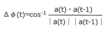
- FIG. 6B is a diagram illustrating an angle difference calculation formula used by the angle difference calculation unit according to Embodiment 1 of the present invention.
- FIG. 7 is a conceptual diagram showing the operation of the time determination unit in Embodiment 1 of the present invention.
- FIG. 8A is a diagram illustrating changes in magnitude and direction of hand acceleration when the hand picks up an object.
- FIG. 8B is a diagram illustrating changes in the magnitude and direction of hand acceleration when the hand places an object.
- FIG. 9 is a conceptual diagram showing a method for determining the overall observation time by the time determination unit in Embodiment 1 of the present invention.
- FIG. 10 is a flowchart of processing executed by the manual operation recognition device according to Embodiment 1 of the present invention.
- FIG. 11 is a diagram for describing a second observation value selection process by the observation value selection unit according to Embodiment 1 of the present invention.
- FIG. 12 is a diagram showing an example of data relating to the color of the foodstuff in the first embodiment of the present invention.
- FIG. 13 is a diagram illustrating an example of a positive example in which a learning device included in the time determination unit according to Embodiment 2 of the present invention learns.
- FIG. 14 is a diagram illustrating an example of a negative example that is learned by the learning device included in the time determination unit according to Embodiment 2 of the present invention.
- FIG. 15 is a flowchart of processing executed by the manual operation recognition device according to Embodiment 2 of the present invention.
- FIG. 16 is an external view of the manual operation recognition apparatus according to Embodiment 1 or 2 of the present invention.
- FIG. 17 is a block diagram showing a hardware configuration of the manual operation recognition device according to Embodiment 1 or 2 of the present invention.
- FIG. 18 is a diagram showing an outline of processing for recognizing a human manual operation disclosed in Non-Patent Document 1.
- a system is considered in which an action of a user corresponding to a closed caption or an object that the user is to act on is acquired in real time from an image of cooking. At this time, according to the embodiment described below, it is possible to efficiently observe only the image that is characteristic of the cooking operation. For this reason, it is not necessary to evaluate all the images, and the user's action or object can be extracted with good response by increasing the processing speed.
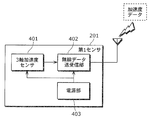
- FIG. 1 shows a form of use of the present invention in actual manual recognition.
- the 2nd sensor 202 is image
- the manual operation recognition device recognizes the operation (places meat on a cutting board). After that, the manual operation recognition device presents the user with a procedure to be followed by the user (cut the meat, immerse it in sauce and let it sleep in the refrigerator for 30 minutes) as a video.
- the first sensor 201 has a built-in acceleration sensor and is mounted on the user's dominant hand.
- the second sensor 202 is a camera and images the entire user's work situation.
- the recognition result in the manual operation recognition device is used as a trigger for processing of the information providing device 203 that provides various information such as presentation of the next work procedure and warning of danger associated with the work.
- FIG. 2 is a functional block diagram showing the configuration of the manual operation recognition system in Embodiment 1 of the present invention.
- the manual operation recognition system is a system for recognizing a user's manual operation, and includes a first sensor 201, a second sensor 202, and a manual operation recognition device 300.
- the manual operation recognition device 300 is a device that recognizes the user's manual operation based on the observation value of the first sensor 201 and the observation value of the second sensor 202.
- the first sensor 201 outputs the first observation value indicating the movement of the user in time series by observing the movement of the hand of the user who performs the manual operation.
- the second sensor 202 observes the situation of the user's manual work and outputs second observation values indicating the situation of the manual work in time series.
- the manual operation recognition apparatus 300 recognizes the user's manual operation based on the first observation value in time series and the second observation value in time series.
- the manual operation recognition apparatus 300 includes an overall observation time determination unit 303, an observation value selection unit 304, and a situation recognition unit 305.
- the overall observation time determination unit 303 determines the observation time (hereinafter referred to as “total observation time”) of the first observation value in which the movement of the user's hand shows a predetermined movement based on the first observation value in time series. To do.
- the observation value selection unit 304 selects the second observation value observed at the overall observation time determined by the overall observation time determination unit 303.
- the situation recognition unit 305 compares the second observation value selected by the observation value selection unit 304 with knowledge data associated with the user's manual operation when the user shows the predetermined movement, thereby Identify manual work.
- the situation recognition unit 305 includes a known recognition unit as described in Non-Patent Document 1. That is, for each manual operation of the user, the situation recognition unit 305 calculates the degree of matching between the knowledge data of the image feature learned in advance and the second observation value, and performs the manual operation of the user corresponding to the most suitable knowledge data. , Output as the current manual recognition result.
- knowledge data is generated by learning the color distribution in the image data.
- the color of the food is characteristic
- knowledge data is generated by learning the color distribution in the image data.
- the temporal change of the color of the food is characteristic
- knowledge data may be generated by learning the temporal change of the color distribution in the time series of the image data. For example, when the onion is chopped, knowledge data may be generated such that the white area increases with time as a temporal change in the color distribution.
- FIG. 3 shows the configuration of the first sensor 201.
- the first sensor 201 includes a triaxial acceleration sensor 401, a wireless data transmission / reception unit 402, and a power supply unit 403.
- the 3-axis acceleration sensor 401 is a small semiconductor accelerometer manufactured using MEMS (Micro Electro Mechanical Systems) technology.
- the triaxial acceleration sensor 401 has a standard specification capable of measuring an acceleration of around ⁇ 3G (G is gravitational acceleration) with respect to the three axes x, y, and z.
- the triaxial acceleration sensor 401 has a specification for outputting data of around 40 samples per second.
- the wireless data transmission / reception unit 402 transmits the observation value (the first observation value) of the triaxial acceleration sensor 401 to the overall observation time determination unit 303 of the manual operation recognition device 300 in real time. At this time, the wireless data transmission / reception unit 402 transmits the observation value to the overall observation time determination unit 303 using a wireless data transmission standard such as Bluetooth (registered trademark) serial port profile.
- a wireless data transmission standard such as Bluetooth (registered trademark) serial port profile.
- the power supply unit 403 is a disposable primary battery or a rechargeable secondary battery that supplies power necessary for these operations to the triaxial acceleration sensor 401 and the wireless data transmission / reception unit 402.
- the first sensor 201 is of a size that can be worn on a person's arm, and is in close contact with the arm so as to react quickly to the movement of the arm.
- FIG. 4 shows the internal configuration of the overall observation time determination unit 303.
- the overall observation time determination unit 303 includes a wireless data transmission / reception unit 504, a magnitude estimation unit 501, an angle difference calculation unit 502, and a time determination unit 503.
- the wireless data transmission / reception unit 504 receives the acceleration a (t) that is an observation value of the triaxial acceleration sensor 401 transmitted from the wireless data transmission / reception unit 402.
- the magnitude estimation unit 501 estimates the magnitude
- gravity acts on the accelerometer (three-axis acceleration sensor 401). Therefore, as shown in FIG. 5A, the acceleration a (t) output from the accelerometer is a vector sum of the gravitational acceleration g and the acceleration ⁇ (t) excluding the gravitational acceleration g.
- the angle ⁇ formed by the gravitational acceleration g and the acceleration excluding the gravitational acceleration g is unknown. For this reason, it is impossible to accurately remove the gravitational acceleration component.
- the angle difference calculation unit 502 determines the acceleration a (t) and the acceleration (a (t ⁇ 1)) and the angle formed by. Specifically, as shown in FIG. 6A, an angle formed by the acceleration a (t) at the measurement time t of interest and the acceleration a (t ⁇ 1) at the previous measurement time (t ⁇ 1) ( (Minimum value 0, maximum value ⁇ , unit is radian). That is, the angle difference calculation unit 502 calculates the angle difference ⁇ (t) according to the calculation formula shown in FIG. 6B.
- the time determination unit 503 sets the measurement time t focused on the calculation of the angle difference ⁇ (t) as the overall observation time when under a predetermined condition.
- the predetermined conditions are the magnitude
- the observation value selection unit 304 selects the second observation value at the determined overall observation time.
- a movement characteristic of placing an object held in the hand after the direction of the hand is stabilized or holding an object placed after the direction of the hand is stabilized is observed. That is, the acceleration of the hand changes sharply after the posture of the hand is stabilized.
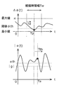
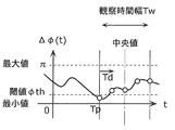
- the time determination unit 503 uses this characteristic to determine the overall observation time. That is, as shown in FIG. 7, the magnitude estimation unit 501 within the predetermined maximum maximum value arrival time Tth immediately after the time Tp when the angle difference ⁇ (t) calculated by the angle difference calculation unit 502 asymptotically approaches 0.
- the time determination unit 503 determines the time Tp at which the angle difference ⁇ (t) asymptotically approaches 0 as a whole. Determined as observation time.
- This process is a process that focuses on the change in the magnitude and direction of the hand acceleration as shown in FIG.
- the processing focuses on the change in the magnitude and direction of the hand acceleration as shown in FIG. 8B.
- the time determination unit 503 moves in the time axis direction while overlapping the constant observation time width Tw, and sequentially samples the value of the angle difference ⁇ (t) included in the observation time width Tw.
- the time during which the angle difference ⁇ (t) continuously decreases from the start time of the observation time width Tw exceeds the preset minimum decrease time Td, and the angle difference ⁇ (t)
- the time determination unit 503 determines the observation time of the minimum value of the angle difference ⁇ (t) as the time Tp.
- immediately after the time Tp is equal to or shorter than the preset maximum maximum value arrival time Tth, and
- the time determination unit 503 outputs the time Tp as the overall observation time. More specifically, when
- Ta ⁇ Tp ⁇ Tth is satisfied and
- the time determination unit 503 outputs the time Tp as the overall observation time.
- the minimum decrease time Td, threshold value ⁇ th, maximum maximum value arrival time Tth, and threshold value ⁇ th are determined by actually observing the user's work and fine-tuning them to values that give appropriate results. . Some of these threshold values may not be present. For example, the determination using the threshold value ⁇ th may be omitted.
- the second sensor 202 is a camera that captures a moving image.
- the second sensor 202 has a specification for outputting color still image data of about 30 frames per second as the second observation value.
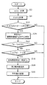
- the magnitude estimation unit 501 estimates the magnitude
- the magnitude estimation unit 501 sequentially estimates
- the angle difference calculation unit 502 calculates the angle (angle difference ⁇ (t) between the acceleration a (t) at the measurement time t of interest and the acceleration a (t ⁇ 1) at the previous measurement time (t ⁇ 1). )) Is calculated (S4).
- the angle difference calculation unit 502 calculates the angle difference ⁇ (t) sequentially for each measurement time t (S4).
- the time determination unit 503 uses the magnitude of the acceleration ⁇ (t)
- the time determination unit 503 sets in advance a time during which the angle difference ⁇ (t) continuously decreases from the start time of the observation time width Tw in the range of the observation time width Tw. It is determined whether or not the minimum decrease time Td is exceeded (S6).
- the time determination unit 503 determines the angle difference ⁇ (t) included in the observation time width Tw. It is determined whether or not the local minimum value is equal to or less than the threshold value ⁇ th (S8).
- the time determination unit 503 determines the observation time of the minimum value of the angle difference ⁇ (t) as the time Tp (S10). ).
- the time determination unit 503 determines that the time from the time Tp to the observation time Ta of the maximum value of
- the time determination unit 503 determines that the maximum value of
- the time determination unit 503 When the maximum value of
- the observation value selection unit 304 selects the second observation value observed by the second sensor 202 at the entire observation time Tp (S18). Thereby, an image as shown in FIG. 11B is selected from an image observed by the second sensor 202 as shown in FIG.
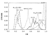
- the situation recognition unit 305 identifies the user's manual operation by comparing the second observation value selected by the observation value selection unit 304 with the knowledge data associated with the user's manual operation (S20). For example, data relating to the color of the food shown in FIG. 12 is prepared as knowledge data, and the color distribution of the pixels constituting the camera image of the second observation value selected by the observation value selection unit 304 as shown in FIG. And the knowledge data are compared to identify the object. In FIG. 12, the horizontal axis indicates the value of the red component of the pixel, and the vertical axis indicates the normalized frequency. Knowledge data such as “skinned onion” or “skinned onion” may be prepared as data relating to a color obtained by further subdividing the object.
- the user's action as shown in FIG. 11B may be identified.
- the object is recognized as “onion” and the action is recognized as “having” by comparison with the knowledge data as described above. Is output.
- the entire observation time is not calculated and the process ends.
- the minimum value of the angle difference ⁇ (t) is larger than the threshold value ⁇ th (NO in S8), the entire observation time is not calculated, and the process ends.
- is equal to or less than the threshold value ⁇ th (NO in S14), the entire observation time is not calculated, and the process ends.
- the above processing from S6 to S20 is repeatedly executed while moving the observation time width Tw shown in FIG. 9 in the time axis direction.
- the second sensor 202 outputs a continuous second observation value.
- the observation value selection unit 304 selects the second observation value to be input to the situation recognition unit 305 as illustrated in FIG. 11B according to the overall observation time Tp determined by the overall observation time determination unit 303.
- the overall observation time determination unit 303 determines the overall observation time Tp in real time according to the processing described above based on changes in the angle difference ⁇ (t) and the magnitude of acceleration
- the situation recognition unit 305 calculates the degree of fitness between the second observation value and the knowledge data of the image feature learned in advance for each manual operation of the user only for the given second observation value. Then, based on the degree of matching, the user's manual work corresponding to the most suitable knowledge data is output as a recognition result of the current manual work. Therefore, the situation recognizing unit 305 can significantly reduce the amount of calculation spent for evaluating the learning knowledge for the input observation value by partially evaluating the second observation value. Therefore, the user's action or object can be extracted with high response by increasing the processing speed.
- Embodiment 2 The manual operation recognition system according to Embodiment 2 is different from the manual operation recognition system according to Embodiment 1 in the method for determining the overall observation time performed by the time determination unit 503. The rest is the same as in the first embodiment. Therefore, detailed description thereof will not be repeated here.
- the time determination unit 503 has a known learning device such as an SVM (Support Vector Machine), a perceptron, or a neuro discriminator, and uses this learning device to determine a time Tp at which the angle difference ⁇ (t) is minimized.
- SVM Serial Vector Machine
- perceptron a perceptron
- neuro discriminator uses this learning device to determine a time Tp at which the angle difference ⁇ (t) is minimized.
- FIG. 13 is a diagram illustrating an example of a positive example used for learning.
- the angle difference ⁇ (t) continuously decreases from the start time of the observation time width Tw to the minimum decrease time Td. Further, the angle difference ⁇ (t) becomes a minimum at the central time (time Tp) of the observation time width Tw, and the minimum value of the angle difference ⁇ (t) becomes equal to or less than a preset threshold value ⁇ th.
- FIG. 14 is a diagram illustrating an example of an angle difference ⁇ (t) indicating a negative example.
- the negative example is a waveform of all angle differences ⁇ (t) other than the positive example.
- the positive condition that the angle difference ⁇ (t) continuously decreases from the start time of the observation time width Tw to the minimum decrease time Td is not satisfied.
- the condition that the angle difference ⁇ (t) is minimum at the central time of the observation time width Tw and the minimum value of the angle difference ⁇ (t) is equal to or less than a preset threshold value ⁇ th is not satisfied.
- the time determination unit 503 moves in the time axis direction while overlapping the constant observation time width Tw, and sequentially samples the value of the angle difference ⁇ (t) included in the observation time width Tw.
- the time determination unit 503 inputs the angle difference ⁇ (t) included in the observation time width Tw to the learning device described above.
- the time determination unit 503 determines the center time of the observation time width Tw as the time Tp when the output of the learning device indicates a positive example, and determines the time Tp when the output of the learning device indicates a negative example. Does not. Thereafter, the time determination unit 503 determines whether or not the time Ta exists, as in the first embodiment, and outputs the time Tp as the overall observation time when the time Ta exists.
- the process executed by the manual operation recognition apparatus in the second embodiment is the same as the process executed by the manual operation recognition apparatus in the first embodiment shown in FIG. 10 except that the processes of S32 and S34 are performed instead of the processes of S6 to S10. Execute. Other processes are the same as those in the first embodiment. Therefore, detailed description thereof will not be repeated here.
- the time determination unit 503 moves in the time axis direction while overlapping the constant observation time width Tw, and sequentially samples the value of the angle difference ⁇ (t) included in the observation time width Tw.
- the time determination unit 503 inputs the angle difference ⁇ (t) included in the observation time width Tw to the learning device described above.
- the time determination unit 503 determines the center time of the observation time width Tw as the time Tp (S34), and the output of the learning device indicates a negative example. In this case (NO in S32), the time Tp is not determined.
- the second sensor 202 outputs a continuous second observation value.
- the observation value selection unit 304 selects the second observation value to be input to the situation recognition unit 305 as illustrated in FIG. 11B according to the overall observation time Tp determined by the overall observation time determination unit 303.
- the overall observation time determination unit 303 determines the overall observation time Tp in real time according to the processing described above based on changes in the angle difference ⁇ (t) and the magnitude of acceleration
- the situation recognition unit 305 calculates the degree of fitness between the second observation value and the knowledge data of the image feature learned in advance for each manual operation of the user only for the given second observation value. Then, based on the degree of matching, the user's manual work corresponding to the most suitable knowledge data is output as a recognition result of the current manual work. Therefore, the situation recognizing unit 305 can significantly reduce the amount of calculation spent for evaluating the learning knowledge for the input observation value by partially evaluating the second observation value. Therefore, the user's action or object can be extracted with high response by increasing the processing speed.
- the user's manual work is recognized.
- the recognition target is not limited to the manual work, and is limited to the manual work as long as the work is associated with the movement of the user's hand.
- the second sensor 202 may image the entire user. Accordingly, the user's motion can be recognized by comparing the second observation value with the knowledge data of the user's motion associated with the user's hand motion. Further, the second sensor 202 may image the user's feet. Thereby, it becomes possible to recognize the work by the user's foot by comparing the second observation value and the knowledge data of the user's foot work associated with the movement of the user's hand.
- observation value selection unit 304 may select not only the second observation value but also the first observation value observed at the same overall observation time.
- observation value selection unit 304 may select not only the second observation value at the whole observation time Tp but also the second observation values of several frames before and after the whole observation time Tp.
- the overall observation time determination unit 303 uses the time Tp as the overall observation time, but may use the time Ta as the overall observation time.
- the learning device of the time determination unit 503 of the second embodiment determines the time Tp only from the angle difference ⁇ (t), but
- the time Tp may be determined by sampling together with (t) and using it together with the angle difference ⁇ (t).
- the operation of the present invention has been described by taking cooking work in a general home as an example, but the present invention is not limited to this.
- the present invention can be used for manual work other than ordinary homes, such as assembly work of home appliances at a production site, as long as it is a manual work carefully performed by a person.
- the result of work recognition can be used for production process management and efficiency improvement.
- the result of work recognition is given to the moving image as an index of moving images accumulated every day. This makes it possible to quickly access a desired work scene when analyzing moving images stored offline later.
- the second sensor may be a microphone that collects sound caused by manual work.
- the situation recognizing unit 305 calculates the degree of matching between the knowledge data of acoustic features learned in advance for each manual operation of the user and the current sound, and calculates the manual operation corresponding to the most suitable knowledge data as the current manual operation. You may output as a recognition result of manual work.
- the second sensor may be a camera that picks up manual work and a microphone that picks up sounds caused by the manual work.
- the situation recognition unit 305 performs processing based on the degree of matching between the image feature knowledge data and acoustic feature knowledge data learned in advance for each manual operation of the user, and the current image and sound. Also good. Specifically, the manual operation corresponding to the most suitable knowledge data may be output as the recognition result of the current manual operation based on the above-described degree of matching.
- a sensor having the same configuration as the first sensor 201 is mounted on both the left and right hands, and the entire observation time determination unit 303 is independently provided for each of the left hand and the right hand. It is possible to increase the second observation value.
- a gyro sensor or an angular velocity sensor in three directions may be integrated into the three-axis acceleration sensor 401 to estimate the attitude of the angular velocity sensor. Accordingly, it is possible to estimate
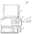
- a manual recognition device 300 includes a computer 34, a keyboard 36 and a mouse 38 for giving instructions to the computer 34, a display 32 for presenting information such as calculation results of the computer 34, A CD-ROM (Compact Disc-Read Only Memory) device 40 for reading a program executed by the computer 34 and a communication modem (not shown) are included.
- a computer 34 includes a computer 34, a keyboard 36 and a mouse 38 for giving instructions to the computer 34, a display 32 for presenting information such as calculation results of the computer 34, A CD-ROM (Compact Disc-Read Only Memory) device 40 for reading a program executed by the computer 34 and a communication modem (not shown) are included.
- CD-ROM Compact Disc-Read Only Memory
- a program for recognizing manual work is stored in a CD-ROM 42 which is a computer-readable medium and is read by the CD-ROM device 40. Alternatively, it is read by a communication modem through the computer network 26.
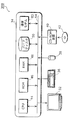
- FIG. 17 is a block diagram showing a hardware configuration of the manual operation recognition device 300.
- the computer 34 includes a CPU (Central Processing Unit) 44, a ROM (Read Only Memory) 46, a RAM (Random Access Memory) 48, a hard disk 50, a communication modem 52, and a bus 54.
- CPU Central Processing Unit
- ROM Read Only Memory
- RAM Random Access Memory
- the CPU 44 executes the program read via the CD-ROM device 40 or the communication modem 52.
- the ROM 46 stores programs and data necessary for the operation of the computer 34.
- the RAM 48 stores data such as parameters at the time of program execution.
- the hard disk 50 stores programs and data.
- the communication modem 52 communicates with other computers via the computer network 26.
- the bus 54 connects the CPU 44, the ROM 46, the RAM 48, the hard disk 50, the communication modem 52, the display 32, the keyboard 36, the mouse 38, and the CD-ROM device 40 to each other.
- the system LSI is a super multifunctional LSI manufactured by integrating a plurality of components on one chip, and specifically, a computer system including a microprocessor, a ROM, a RAM, and the like. .
- a computer program is stored in the RAM.
- the system LSI achieves its functions by the microprocessor operating according to the computer program.
- each of the above-described devices may be configured from an IC card or a single module that can be attached to and detached from each device.
- the IC card or module is a computer system that includes a microprocessor, ROM, RAM, and the like.
- the IC card or the module may include the super multifunctional LSI described above.
- the IC card or the module achieves its function by the microprocessor operating according to the computer program. This IC card or this module may have tamper resistance.
- the present invention may be the method described above. Further, the present invention may be a computer program that realizes these methods by a computer, or may be a digital signal composed of the computer program.
- the present invention provides a computer-readable recording medium such as a flexible disk, hard disk, CD-ROM, MO, DVD, DVD-ROM, DVD-RAM, BD (Blu-ray Disc). (Registered trademark)), or recorded in a semiconductor memory or the like. Further, the digital signal may be recorded on these recording media.
- a computer-readable recording medium such as a flexible disk, hard disk, CD-ROM, MO, DVD, DVD-ROM, DVD-RAM, BD (Blu-ray Disc). (Registered trademark)), or recorded in a semiconductor memory or the like.
- the digital signal may be recorded on these recording media.
- the computer program or the digital signal may be transmitted via an electric communication line, a wireless or wired communication line, a network represented by the Internet, data broadcasting, or the like.
- the present invention may also be a computer system including a microprocessor and a memory.
- the memory may store the computer program, and the microprocessor may operate according to the computer program.
- the program or the digital signal is recorded on the recording medium and transferred, or the program or the digital signal is transferred via the network or the like, and is executed by another independent computer system. It is also good.
- the manual operation recognition system has high-speed user operation recognition performance, and is useful as an operation trigger for white goods, housework support robots, and the like. It can also be applied to work recognition applications such as cleaning and washing, and monitoring applications such as assembly work in factories.
Landscapes
- Engineering & Computer Science (AREA)
- General Engineering & Computer Science (AREA)
- Theoretical Computer Science (AREA)
- Physics & Mathematics (AREA)
- Health & Medical Sciences (AREA)
- Human Computer Interaction (AREA)
- General Physics & Mathematics (AREA)
- Life Sciences & Earth Sciences (AREA)
- Pathology (AREA)
- Medical Informatics (AREA)
- Dentistry (AREA)
- Biophysics (AREA)
- Physiology (AREA)
- Biomedical Technology (AREA)
- Heart & Thoracic Surgery (AREA)
- Oral & Maxillofacial Surgery (AREA)
- Molecular Biology (AREA)
- Surgery (AREA)
- Animal Behavior & Ethology (AREA)
- General Health & Medical Sciences (AREA)
- Public Health (AREA)
- Veterinary Medicine (AREA)
- Image Analysis (AREA)
- Position Input By Displaying (AREA)
Abstract
Priority Applications (3)
| Application Number | Priority Date | Filing Date | Title |
|---|---|---|---|
| JP2010541638A JP4719826B2 (ja) | 2009-06-08 | 2010-05-21 | 作業認識装置 |
| CN201080003376.8A CN102227697B (zh) | 2009-06-08 | 2010-05-21 | 操作识别系统、操作识别装置及操作识别方法 |
| US13/056,789 US8654187B2 (en) | 2009-06-08 | 2010-05-21 | Work recognition system, work recognition device, and work recognition method |
Applications Claiming Priority (2)
| Application Number | Priority Date | Filing Date | Title |
|---|---|---|---|
| JP2009-137761 | 2009-06-08 | ||
| JP2009137761 | 2009-06-08 |
Publications (1)
| Publication Number | Publication Date |
|---|---|
| WO2010143361A1 true WO2010143361A1 (fr) | 2010-12-16 |
Family
ID=43308624
Family Applications (1)
| Application Number | Title | Priority Date | Filing Date |
|---|---|---|---|
| PCT/JP2010/003419 Ceased WO2010143361A1 (fr) | 2009-06-08 | 2010-05-21 | Système de reconnaissance d'opération, dispositif de reconnaissance d'opération et procédé de reconnaissance d'opération |
Country Status (4)
| Country | Link |
|---|---|
| US (1) | US8654187B2 (fr) |
| JP (1) | JP4719826B2 (fr) |
| CN (1) | CN102227697B (fr) |
| WO (1) | WO2010143361A1 (fr) |
Cited By (5)
| Publication number | Priority date | Publication date | Assignee | Title |
|---|---|---|---|---|
| JP2014517384A (ja) * | 2011-05-04 | 2014-07-17 | クアルコム,インコーポレイテッド | オブジェクトを遠隔制御するためのアドホック近接センサーメッシュを介したジェスチャー認識 |
| JP2019101516A (ja) * | 2017-11-29 | 2019-06-24 | ファナック株式会社 | 作業者管理装置 |
| DE102019007415A1 (de) | 2018-10-31 | 2020-04-30 | Fanuc Corporation | Anzeigesystem, maschinenlerneinrichtung und anzeigeeinrichtung |
| JP2021144576A (ja) * | 2020-03-13 | 2021-09-24 | 株式会社リコー | 情報処理装置、情報処理方法およびプログラム |
| US11443266B2 (en) | 2019-08-19 | 2022-09-13 | Fanuc Corporation | Machine learning method and machine learning apparatus performing learning relating to work process |
Families Citing this family (3)
| Publication number | Priority date | Publication date | Assignee | Title |
|---|---|---|---|---|
| DE102012110190B4 (de) * | 2012-10-25 | 2015-03-26 | Mis-Robotics Gmbh | Manuell betätigte Robotersteuerung und Verfahren zum Steuern eines Robotersystems |
| JP5956481B2 (ja) * | 2014-02-10 | 2016-07-27 | レノボ・シンガポール・プライベート・リミテッド | 入力装置、入力方法、及びコンピュータが実行可能なプログラム |
| CN104730931B (zh) * | 2015-03-12 | 2019-10-22 | 青岛海尔智能家电科技有限公司 | 一种美食交互系统和美食食谱的生成方法 |
Citations (2)
| Publication number | Priority date | Publication date | Assignee | Title |
|---|---|---|---|---|
| JP2006215680A (ja) * | 2005-02-02 | 2006-08-17 | Advanced Telecommunication Research Institute International | 誤作業警報システム |
| JP2009110038A (ja) * | 2007-10-26 | 2009-05-21 | Advanced Telecommunication Research Institute International | 情報提示システム |
Family Cites Families (13)
| Publication number | Priority date | Publication date | Assignee | Title |
|---|---|---|---|---|
| JPH08320920A (ja) | 1995-05-24 | 1996-12-03 | Matsushita Electric Ind Co Ltd | 手動作認識装置および方法 |
| JP3440641B2 (ja) | 1995-07-26 | 2003-08-25 | 松下電器産業株式会社 | 動作開始位置検出方法 |
| US6430997B1 (en) * | 1995-11-06 | 2002-08-13 | Trazer Technologies, Inc. | System and method for tracking and assessing movement skills in multidimensional space |
| EP0816986B1 (fr) * | 1996-07-03 | 2006-09-06 | Hitachi, Ltd. | Système de reconnaissance du mouvement |
| JP3570163B2 (ja) | 1996-07-03 | 2004-09-29 | 株式会社日立製作所 | 動作及び行動の認識方法及び装置及びシステム |
| JPH11174948A (ja) | 1997-09-26 | 1999-07-02 | Matsushita Electric Ind Co Ltd | 手動作認識装置 |
| EP0905644A3 (fr) | 1997-09-26 | 2004-02-25 | Matsushita Electric Industrial Co., Ltd. | Dispositif de reconnaissance de gestes de la main |
| JP2003281297A (ja) | 2002-03-22 | 2003-10-03 | National Institute Of Advanced Industrial & Technology | 情報提示装置および情報提示方法 |
| SG115546A1 (en) | 2003-06-23 | 2005-10-28 | Affineon Technologies Pte Ltd | Computer input device tracking six degrees of freedom |
| WO2005003945A1 (fr) | 2003-07-02 | 2005-01-13 | Ssd Company Limited | Dispositif et systeme de traitement de donnees, article fonctionnel, procede et programme de traitement de donnees, et systeme de jeu |
| JP2006133937A (ja) | 2004-11-04 | 2006-05-25 | Fuji Xerox Co Ltd | 動作識別装置 |
| JP2007172577A (ja) | 2005-11-25 | 2007-07-05 | Victor Co Of Japan Ltd | 操作情報入力装置 |
| JP5091591B2 (ja) | 2007-08-30 | 2012-12-05 | 株式会社東芝 | 情報処理装置、プログラム及び情報処理方法 |
-
2010
- 2010-05-21 US US13/056,789 patent/US8654187B2/en not_active Expired - Fee Related
- 2010-05-21 CN CN201080003376.8A patent/CN102227697B/zh not_active Expired - Fee Related
- 2010-05-21 WO PCT/JP2010/003419 patent/WO2010143361A1/fr not_active Ceased
- 2010-05-21 JP JP2010541638A patent/JP4719826B2/ja active Active
Patent Citations (2)
| Publication number | Priority date | Publication date | Assignee | Title |
|---|---|---|---|---|
| JP2006215680A (ja) * | 2005-02-02 | 2006-08-17 | Advanced Telecommunication Research Institute International | 誤作業警報システム |
| JP2009110038A (ja) * | 2007-10-26 | 2009-05-21 | Advanced Telecommunication Research Institute International | 情報提示システム |
Cited By (8)
| Publication number | Priority date | Publication date | Assignee | Title |
|---|---|---|---|---|
| JP2014517384A (ja) * | 2011-05-04 | 2014-07-17 | クアルコム,インコーポレイテッド | オブジェクトを遠隔制御するためのアドホック近接センサーメッシュを介したジェスチャー認識 |
| JP2019101516A (ja) * | 2017-11-29 | 2019-06-24 | ファナック株式会社 | 作業者管理装置 |
| US11216757B2 (en) | 2017-11-29 | 2022-01-04 | Fanuc Corporation | Worker management device |
| DE102019007415A1 (de) | 2018-10-31 | 2020-04-30 | Fanuc Corporation | Anzeigesystem, maschinenlerneinrichtung und anzeigeeinrichtung |
| US11119716B2 (en) | 2018-10-31 | 2021-09-14 | Fanuc Corporation | Display system, machine learning device, and display device |
| US11443266B2 (en) | 2019-08-19 | 2022-09-13 | Fanuc Corporation | Machine learning method and machine learning apparatus performing learning relating to work process |
| JP2021144576A (ja) * | 2020-03-13 | 2021-09-24 | 株式会社リコー | 情報処理装置、情報処理方法およびプログラム |
| JP7167953B2 (ja) | 2020-03-13 | 2022-11-09 | 株式会社リコー | 情報処理装置、情報処理方法およびプログラム |
Also Published As
| Publication number | Publication date |
|---|---|
| US8654187B2 (en) | 2014-02-18 |
| CN102227697B (zh) | 2014-12-10 |
| CN102227697A (zh) | 2011-10-26 |
| JPWO2010143361A1 (ja) | 2012-11-22 |
| US20110128363A1 (en) | 2011-06-02 |
| JP4719826B2 (ja) | 2011-07-06 |
Similar Documents
| Publication | Publication Date | Title |
|---|---|---|
| JP4719826B2 (ja) | 作業認識装置 | |
| US20220189211A1 (en) | Physical activity quantification and monitoring | |
| JP6745980B2 (ja) | 水泳分析のシステム及び方法 | |
| Chen et al. | A fall detection system based on infrared array sensors with tracking capability for the elderly at home | |
| CN105184325B (zh) | 一种移动智能终端 | |
| KR101872907B1 (ko) | 듀얼 스마트 밴드를 이용한 모션 분석 장치 및 방법 | |
| JP6951516B2 (ja) | 人の歩調を検出する方法及びシステム | |
| JPWO2018051944A1 (ja) | 人流推定装置、人流推定方法およびプログラム | |
| CN111402287B (zh) | 用于活动序列的标准化评估的系统和方法 | |
| Jensen et al. | Classification of kinematic swimming data with emphasis on resource consumption | |
| JP2021030051A (ja) | 転倒リスク評価方法、転倒リスク評価装置及び転倒リスク評価プログラム | |
| US11450148B2 (en) | Movement monitoring system | |
| US20240057946A1 (en) | Sarcopenia evaluation method, sarcopenia evaluation device, and non-transitory computer-readable recording medium in which sarcopenia evaluation program is recorded | |
| Hossain et al. | A direction-sensitive fall detection system using single 3D accelerometer and learning classifier | |
| KR20180110443A (ko) | 열량 정보 제공 장치 및 방법 | |
| KR20180020123A (ko) | 비동기 신호 처리 방법 | |
| Wu et al. | A multi-sensor fall detection system based on multivariate statistical process analysis | |
| US20230127086A1 (en) | Behavior recognition device, behavior recognition method, and non-transitory computer-readable recording medium | |
| JP2012524578A (ja) | 可動要素の活動を決定するためのシステム及び方法 | |
| JP6287827B2 (ja) | 情報処理装置、情報処理方法、及びプログラム | |
| JP2021081804A (ja) | 状態認識装置、状態認識方法及び状態認識プログラム | |
| JP2006198073A (ja) | 体動検出機および体動検出機を備える携帯端末装置 | |
| WO2017154477A1 (fr) | Dispositif d'estimation de pouls, système d'estimation de pouls et procédé d'estimation de pouls | |
| JP7091629B2 (ja) | 検出システム、検出方法及び検出プログラム | |
| CN120770813A (zh) | 用于眼睛凝视指标确定和心理生理状态检测的方法和系统 |
Legal Events
| Date | Code | Title | Description |
|---|---|---|---|
| WWE | Wipo information: entry into national phase |
Ref document number: 201080003376.8 Country of ref document: CN |
|
| ENP | Entry into the national phase |
Ref document number: 2010541638 Country of ref document: JP Kind code of ref document: A |
|
| WWE | Wipo information: entry into national phase |
Ref document number: 13056789 Country of ref document: US |
|
| 121 | Ep: the epo has been informed by wipo that ep was designated in this application |
Ref document number: 10785893 Country of ref document: EP Kind code of ref document: A1 |
|
| NENP | Non-entry into the national phase |
Ref country code: DE |
|
| 122 | Ep: pct application non-entry in european phase |
Ref document number: 10785893 Country of ref document: EP Kind code of ref document: A1 |