WO2010143378A1 - Unité intérieure de climatiseur - Google Patents
Unité intérieure de climatiseur Download PDFInfo
- Publication number
- WO2010143378A1 WO2010143378A1 PCT/JP2010/003704 JP2010003704W WO2010143378A1 WO 2010143378 A1 WO2010143378 A1 WO 2010143378A1 JP 2010003704 W JP2010003704 W JP 2010003704W WO 2010143378 A1 WO2010143378 A1 WO 2010143378A1
- Authority
- WO
- WIPO (PCT)
- Prior art keywords
- flap
- indoor unit
- air conditioner
- rotation
- drive
- Prior art date
- Legal status (The legal status is an assumption and is not a legal conclusion. Google has not performed a legal analysis and makes no representation as to the accuracy of the status listed.)
- Ceased
Links
Images




Classifications
-
- F—MECHANICAL ENGINEERING; LIGHTING; HEATING; WEAPONS; BLASTING
- F24—HEATING; RANGES; VENTILATING
- F24F—AIR-CONDITIONING; AIR-HUMIDIFICATION; VENTILATION; USE OF AIR CURRENTS FOR SCREENING
- F24F1/00—Room units for air-conditioning, e.g. separate or self-contained units or units receiving primary air from a central station
- F24F1/0007—Indoor units, e.g. fan coil units
- F24F1/0011—Indoor units, e.g. fan coil units characterised by air outlets
-
- F—MECHANICAL ENGINEERING; LIGHTING; HEATING; WEAPONS; BLASTING
- F24—HEATING; RANGES; VENTILATING
- F24F—AIR-CONDITIONING; AIR-HUMIDIFICATION; VENTILATION; USE OF AIR CURRENTS FOR SCREENING
- F24F13/00—Details common to, or for air-conditioning, air-humidification, ventilation or use of air currents for screening
- F24F13/08—Air-flow control members, e.g. louvres, grilles, flaps or guide plates
- F24F13/10—Air-flow control members, e.g. louvres, grilles, flaps or guide plates movable, e.g. dampers
- F24F13/14—Air-flow control members, e.g. louvres, grilles, flaps or guide plates movable, e.g. dampers built up of tilting members, e.g. louvre
- F24F13/1426—Air-flow control members, e.g. louvres, grilles, flaps or guide plates movable, e.g. dampers built up of tilting members, e.g. louvre characterised by actuating means
-
- F—MECHANICAL ENGINEERING; LIGHTING; HEATING; WEAPONS; BLASTING
- F24—HEATING; RANGES; VENTILATING
- F24F—AIR-CONDITIONING; AIR-HUMIDIFICATION; VENTILATION; USE OF AIR CURRENTS FOR SCREENING
- F24F13/00—Details common to, or for air-conditioning, air-humidification, ventilation or use of air currents for screening
- F24F13/08—Air-flow control members, e.g. louvres, grilles, flaps or guide plates
- F24F13/10—Air-flow control members, e.g. louvres, grilles, flaps or guide plates movable, e.g. dampers
- F24F13/14—Air-flow control members, e.g. louvres, grilles, flaps or guide plates movable, e.g. dampers built up of tilting members, e.g. louvre
- F24F13/1426—Air-flow control members, e.g. louvres, grilles, flaps or guide plates movable, e.g. dampers built up of tilting members, e.g. louvre characterised by actuating means
- F24F2013/1446—Air-flow control members, e.g. louvres, grilles, flaps or guide plates movable, e.g. dampers built up of tilting members, e.g. louvre characterised by actuating means with gearings
Definitions
- the present invention relates to an indoor unit of an air conditioner.
- some indoor units of an air conditioner include a flap that opens and closes an air outlet from which conditioned air is blown by rotating around a rotation shaft provided at an end portion.
- a flap that can adjust the air direction of the blown-out air by adjusting the rotation angle of the flap with respect to the blowout port when the blowout port is opened.
- the rotation angle of the flap may be limited due to the relationship with the opening area of the outlet. Therefore, the air conditioner disclosed in Patent Document 1 (Japanese Patent Application Laid-Open No.
- 2008-39252 opens and closes the outlet and changes the vertical direction of the blown air (up and down direction change blades) (corresponding to a flap). And an arm portion that rotatably holds the rotation support portion of the up / down airflow direction change blade.
- the arm portion driving motor is driven so that the up / down airflow direction changing blades arranged so as to cover the blowout port are armed together with the rotating shaft.
- the part is moved to the front of the outlet and the outlet is opened.
- the blade driving motor is driven to rotate the up / down wind direction changing blade about the rotation axis, thereby changing the blowing direction of the air blown out from the blowing port.
- the air conditioner disclosed in Patent Document 1 has a problem that a plurality of motors are required to rotate the up / down airflow direction changing blades, and the number of parts increases. Then, the subject of this invention is providing the indoor unit of the air conditioner which can reduce a number of parts.
- the indoor unit of the air conditioner according to the first aspect of the present invention includes a flap, a motor for rotating the rotating shaft, and a flap drive mechanism.
- the flap is rotatable about a rotation axis in order to adjust the air direction of the air blown out from the outlet.
- the flap drive mechanism can perform a rotation operation and a position change operation by rotating the rotation shaft.
- the rotation operation is an operation for rotating the flap about the rotation axis.
- the position changing operation is an operation for changing the position of the rotating shaft with respect to the flap.
- the rotation operation and the position change operation are performed by rotating the rotation shaft by the same motor.
- An indoor unit of an air conditioner according to a second aspect of the present invention is the indoor unit of the air conditioner of the first aspect, wherein the flap drive mechanism rotates when the position of the rotation shaft with respect to the flap is at a predetermined first position. Perform dynamic movement. For this reason, in the indoor unit of this air conditioner, the flap can be rotated when the position of the rotation shaft with respect to the flap is at the predetermined first position.
- An indoor unit of an air conditioner according to a third invention is the indoor unit of the air conditioner of the first invention or the second invention, and the flap drive mechanism rotates when the position changing operation is performed. It is comprised so that operation
- An air conditioner indoor unit is the air conditioner indoor unit of any one of the first to third aspects, wherein the flap drive mechanism has a gear and a rack that meshes with the gear.
- the gear rotates as the rotating shaft rotates.
- the rack is provided on the flap. For this reason, the driving force of the motor can be transmitted to the flap via the gear and the rack.
- An air conditioner indoor unit is the air conditioner indoor unit of any one of the first to fourth aspects, wherein the flap drive mechanism includes a first flap drive mechanism and a second flap drive. Mechanism. Further, the first flap driving mechanism and the second flap driving mechanism are respectively arranged so as to be separated by a predetermined interval in the longitudinal direction of the flap. For this reason, in this air conditioner, a rotating operation and a position changing operation can be performed by a plurality of flap driving mechanisms.
- An indoor unit of an air conditioner according to a sixth aspect is the indoor unit of an air conditioner according to the fifth aspect, wherein the first flap drive mechanism and the second flap drive mechanism are arranged in the vicinity of both ends of the flap, respectively. Has been. For this reason, for example, compared with the case where the flap drive mechanism is provided only in the vicinity of one end of the flap, it is possible to reduce the possibility that the rotating operation and the position changing operation are not performed smoothly. As a result, it is possible to reduce the possibility that the rotating operation and the position changing operation are not performed.
- An indoor unit for an air conditioner according to a seventh aspect is the indoor unit for an air conditioner according to the fifth aspect or the sixth aspect, wherein the rotational axis is a first rotational axis corresponding to the first flap drive mechanism, And a second rotating shaft corresponding to the two-flap drive mechanism.
- the motor includes a first motor for rotating the first rotation shaft and a second motor for rotating the second rotation shaft.
- the indoor unit of the air conditioner according to the eighth aspect of the present invention is the indoor unit of the air conditioner of the seventh aspect, wherein the motor is controlled by the control unit.
- the control unit can individually control the first motor and the second motor. For this reason, in this indoor unit of an air conditioner, a plurality of motors can be individually controlled. Therefore, for example, when the motor is disposed on both ends of the flap, the protruding dimension of the end of the flap with respect to the outlet can be freely changed at each end.
- An indoor unit for an air conditioner according to a ninth aspect of the present invention is the indoor unit for an air conditioner according to any one of the first to sixth aspects, wherein the motor is disposed on one end side in the longitudinal direction of the flap.
- the motor rotates a rotating shaft corresponding to the flap driving mechanism.
- the rotating shaft corresponding to a flap drive mechanism can be rotated with one motor. Therefore, for example, compared to a case where a plurality of motors for rotating a plurality of rotating shafts corresponding to each of a plurality of flap driving mechanisms are provided, the number of motors and the number of electric wires required for driving the motors Can be reduced.
- An indoor unit of an air conditioner according to a tenth aspect of the present invention is the indoor unit of the air conditioner of any one of the first to ninth aspects, wherein the flap drive mechanism continuously performs a rotation operation and a position change operation. And do it. For this reason, in this air conditioner, the rotating operation and the position changing operation can be performed continuously.
- An air conditioner indoor unit is the air conditioner indoor unit of any one of the first to tenth aspects of the invention, wherein the flap is rotated while the position changing operation is being performed. Further provided is a rotation preventing member for preventing the rotation. For this reason, in this indoor unit of an air conditioner, it is possible to reduce the possibility that the flap rotates while the position of the rotation shaft with respect to the flap is changed.
- An air conditioner indoor unit is the air conditioner indoor unit of any of the first to eleventh aspects of the present invention, wherein the flap drive mechanism has a flap rotation angle at a fully closed angle.
- the position changing operation is performed.
- the fully closed angle is a rotation angle at which the flap covers the outlet.
- the number of components can be reduced.
- the flap can be rotated when the position of the rotary shaft with respect to the flap is at the predetermined first position.
- the driving force of the motor can be transmitted to the flap via the gear and the rack.
- the rotating operation and the position changing operation can be performed by a plurality of flap driving mechanisms.
- the indoor unit for an air conditioner according to the seventh aspect of the present invention it is possible to reduce the possibility that the rotating operation and the position changing operation will not be performed.
- the protruding dimension of the end of the flap with respect to the outlet can be freely changed at each end.
- the number of motors and the number of electric wires required to drive the motor can be reduced.
- the rotation operation and the position changing operation can be performed continuously.
- the possibility that the flap rotates while the position of the rotary shaft with respect to the flap is changed can be reduced.
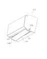
- the front view of an air harmony machine provided with the indoor unit concerning one embodiment of the present invention.
- cooling operation is performed in the air conditioner.
- the longitudinal cross-sectional view of the indoor unit in case heating operation is performed in an air conditioner.
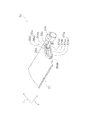
- FIG. 1 is a front view of the air conditioner 1.
- the air conditioner 1 includes an indoor unit 10 attached to an indoor wall surface and an outdoor unit 20 installed outside the room, and can perform various operations such as a cooling operation and a heating operation.
- the indoor unit 10 and the outdoor unit 20 are connected to each other by a collective connecting pipe 2 in which refrigerant pipes, humidification hoses, electric wires, communication lines, and the like are assembled.
- the outdoor unit 20 includes an outdoor air conditioning unit 21 and a humidity control unit 22 disposed on the outdoor air conditioning unit 21.
- the outdoor air conditioning unit 21 is connected to the compressor 23, a four-way switching valve 24 connected to the discharge side of the compressor 23, an accumulator connected to the suction side of the compressor 23, and the four-way switching valve 24.
- an outdoor expansion valve 26 connected to the outdoor heat exchanger (see FIG. 10).
- the outdoor expansion valve 26 is connected to one end of the indoor heat exchanger 12 to be described later via a refrigerant pipe.
- the four-way switching valve 24 is connected to the other end of the indoor heat exchanger 12 through a refrigerant pipe.
- An outdoor fan 25 is provided in the outdoor air conditioning unit 21 (see FIG. 10).
- the outdoor fan 25 is a propeller fan that takes in outdoor air and discharges the air after heat exchange in the outdoor heat exchanger to the outside.
- the humidity control unit 22 may supply outdoor air or humidity control air to the indoor unit 10 side or exhaust indoor air to the outdoor side via a humidifying hose and a humidifying duct disposed inside the indoor unit 10. it can.
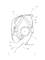
- FIG. 2 is a cross-sectional view of the indoor unit 10 when the air conditioner 1 is performing a cooling operation.
- FIG. 3 is a cross-sectional view of the indoor unit 10 when the air conditioner 1 is performing a heating operation. 2 and 3, an arrow j indicates a front direction that is a direction toward the front side of the indoor unit 10, and an arrow k indicates a rear direction that is a direction toward the rear side of the indoor unit 10.
- the indoor unit 10 is a wall-mounted indoor unit that is attached to an indoor wall surface or the like, and mainly includes an indoor unit casing 11, an indoor heat exchanger 12, a crossflow fan 13, and a flap 30.
- the indoor unit casing 11 accommodates an indoor heat exchanger 12, a cross flow fan 13, and the like.
- the indoor unit casing 11 is formed with an intake port 14 and a blowout port 15.
- the intake port 14 is provided in the upper part of the indoor unit casing 11 and is an opening for taking indoor air into the indoor unit casing 11.
- the blowout port 15 is provided in the lower part of the front surface of the indoor unit casing 11 and is an opening for blowing out conditioned air in the indoor unit 10.
- the indoor heat exchanger 12 includes a heat transfer tube 12a that is bent back and forth at both ends in the longitudinal direction, and a plurality of fins 12b that are inserted into the heat transfer tube 12a, and performs heat exchange with the air that is in contact therewith.
- the indoor heat exchanger 12 functions as a condenser during heating operation and functions as an evaporator during cooling operation.
- the cross flow fan 13 has a motor (not shown) as a drive mechanism and an impeller that is rotationally driven by the motor. Further, the cross flow fan 13 can suck air from the intake port 14 into the indoor unit casing 11, pass the indoor heat exchanger 12, and then blow the air out of the indoor unit casing 11 from the blowout port 15.
- the flap 30 is disposed in the vicinity of the air outlet 15, and can open and close the air outlet 15 by rotating or moving. Further, the flap 30 can change the air direction of the air blown out from the air outlet 15 into the room by adjusting the inclination angle with respect to the air outlet 15. Next, the configuration of the flap 30 provided in the indoor unit 10 will be described.
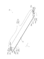
- FIG. 4 is a perspective view of the flap 30.
- FIG. 5 is a partially enlarged view of the flap 30.
- the flap 30 mainly includes a flap main body 31, flap drive motors 33a and 33b, and flap drive mechanisms 30a and 30b.
- the flap body 31 is a plate-like member having a shape that is long in the longitudinal direction of the indoor unit 10. Further, the flap body 31 has an area substantially the same as the opening area of the outlet 15. For this reason, the flap main body 31 can cover substantially the entire outlet 15. Further, the flap body 31 is connected to a rotating shaft 32 extending in the longitudinal direction of the indoor unit 10 through meshing of gears 38a and 38b and racks 39a and 39b, which will be described later.
- the rotation shaft 32 includes two drive shafts 35a and 35b. Further, the drive shafts 35 a and 35 b extend in parallel to the longitudinal direction h of the flap body 31 and are disposed in the vicinity of both end portions of the flap body 31.
- the longitudinal direction h of the flap main body 31 in this embodiment is a direction parallel to the longitudinal direction of the indoor unit 10. Furthermore, the flap main body 31 can change the blowing direction of the air blown out from the blowing port 15 by rotating around the rotation shaft 32.
- the flap drive motors 33a and 33b are stepping motors that can rotate forward and backward, and include a first flap drive motor 33a and a second flap drive motor 33b.
- the flap drive motors 33a and 33b are connected to the drive shafts 35a and 35b, respectively, and rotate the drive shafts 35a and 35b.
- the rotation direction and the number of rotations of the flap drive motors 33a and 33b are controlled by the control unit 60 described later.
- the flap drive mechanisms 30a and 30b have a first flap drive mechanism 30a and a second flap drive mechanism 30b, and are respectively disposed near both ends of the flap body 31.
- the first flap drive mechanism 30 a is disposed in the vicinity of one end of the flap body 31.
- the second flap drive mechanism 30b is disposed near the other end of the flap body 31.
- each flap drive mechanism 30a, 30b has moving members 36a, 36b and gears 38a, 38b, respectively.
- the moving members 36a and 36b are members that are long in a direction i orthogonal to the longitudinal direction h of the flap body 31, and are provided at both ends of the flap body 31 in the longitudinal direction h (see FIG. 5).
- the moving members 36 a and 36 b have an oval shape in a side view and are fixed to the upper surface of the flap body 31.
- the moving members 36a and 36b are formed with long holes 37a and 37b for the gears 38a and 38b to enter.
- the long holes 37a and 37b are composed of circular arc surface portions (37aa; see FIG. 5) at both ends, an upper surface portion (37ab; see FIG. 5) connecting the two arc surface portions, and a lower surface portion (37ac; see FIG. 5).
- racks 39a and 39b that mesh with the gears 38a and 38b are formed on the upper surfaces of the long holes 37a and 37b.
- the long holes 37a and 37b are formed so as to extend in the longitudinal direction of the moving members 36a and 36b, that is, in the direction i orthogonal to the longitudinal direction h of the flap body 31. Further, the direction i orthogonal to the longitudinal direction h of the flap body 31 in the present embodiment is a direction substantially parallel to the front-rear direction of the indoor unit 10. For this reason, each circular arc surface part of the long holes 37a and 37b is arrange
- the gears 38a and 38b are fixed to the ends of the drive shafts 35a and 35b.
- the gears 38a and 38b rotate with the rotation of the drive shafts 35a and 35b. For this reason, when each flap drive motor 33a, 33b drives, each drive shaft 35a, 35b and each gear 38a, 38b rotate. In other words, when the first flap drive motor 33a is driven, the drive shaft 35a and the gear 38a are rotated. Further, when the second flap drive motor 33b is driven, the drive shaft 35b and the gear 38b are rotated.
- the gears 38a and 38b mesh with racks 39a and 39b included in the moving members 36a and 36b.
- the flap drive mechanisms 30a and 30b constitute a rack / pinion mechanism, and transmit the driving force of the flap drive motors 33a and 33b to the flap body 31 via the gears 38a and 38b and the racks 39a and 39b. be able to.
- the flap drive mechanisms 30a and 30b are configured so that the drive shafts 35a and 35b are rotated by the flap drive motors 33a and 33b and the power is transmitted to the gears 38a and 38b and the racks 39a and 39b.
- Rotating the flap body 31 about 32 and rotating the flap body 31 to change the inclination angle of the flap body 31 with respect to the outlet 15, that is, the posture of the flap body 31, or moving the flap body 31 in the front-rear direction of the indoor unit 10 Move operation (equivalent to position change operation) to be performed. This moving operation is performed in a state in which the posture of the flap body 31 is maintained.
- the flap 30 includes a guide roller 40 (see FIG. 6).
- the guide roller 40 is disposed so as to face the gears 38a and 38b with the upper portions of the moving members 36a and 36b including the upper surface portions where the racks 39a and 39b are provided in the moving members 36a and 36b.
- the guide roller 40 is configured to support the moving members 36 a and 36 b from the upper side and to rotate with the movement of the rotating shaft 32.
- the rotation operation of the flap drive mechanisms 30a and 30b and the movement operation of the flap drive mechanisms 30a and 30b will be described.
- the direction in which the flap main body 31 rotates about the rotation shaft 32 is referred to as a rotation direction
- the direction in which the flap main body 31 moves in a direction different from the rotation direction A direction substantially parallel to the longitudinal direction of the machine 10 is referred to as a moving direction.
- the flap drive mechanisms 30a and 30b can rotate the flap body 31 in the rotation direction by driving the flap drive motors 33a and 33b and rotating the rotary shaft 32.
- the flap drive mechanisms 30a and 30b can transmit the rotation of the rotary shaft 32 by the flap drive motors 33a and 33b to the flap body 31 as a rotational motion.
- the flap drive mechanisms 30a and 30b can open and close the outlet 15 by rotating the flap body 31 about the rotation shaft 32 in the rotation direction.
- the flap drive mechanisms 30a and 30b rotate the flap body 31 in the turning direction around the rotation shaft 32 to adjust the turning angle of the flap body 31 with respect to the outlet 15, that is, the inclination angle.
- the air direction of the air blown into the room from the blowout port 15 can be changed.
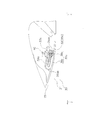
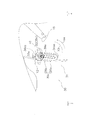
- FIG. 6 is a conceptual diagram of the vicinity of the air outlet 15 of the indoor unit 10 viewed from the direction of arrow B in FIG. 1, and shows the state of the flap 30 when the operation of the air conditioner 1 is stopped.
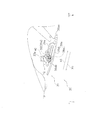
- FIG. 7 is a conceptual diagram of the vicinity of the air outlet 15 of the indoor unit 10 as viewed from the direction of arrow B in FIG. 1, and is a diagram illustrating a state of the flap 30 when the air conditioner 1 is performing a cooling operation. is there.
- FIG. 6 is a conceptual diagram of the vicinity of the air outlet 15 of the indoor unit 10 viewed from the direction of arrow B in FIG. 1, and shows the state of the flap 30 when the operation of the air conditioner 1 is stopped.
- FIG. 7 is a conceptual diagram of the vicinity of the air outlet 15 of the indoor unit 10 as viewed from the direction of arrow B in FIG. 1, and is a diagram illustrating a state of the flap 30 when the air conditioner 1 is performing a cooling operation. is there.
- FIG. 6 is a conceptual diagram of the vicinity of
- FIG. 8 is a conceptual diagram of the vicinity of the air outlet 15 of the indoor unit 10 as viewed from the direction of arrow B in FIG. 1, and is a diagram illustrating the state of the flap 30 when the air conditioner 1 is performing the heating operation. is there. 6, 7, 8, and 9, an arrow j indicates a front direction that is a direction toward the front side of the indoor unit 10, and an arrow k is a direction that is directed toward the rear side of the indoor unit 10. Shows direction. Furthermore, from below, in the closed state, of the end portions of the moving members 36a and 36b, an end portion closer to the rear side of the indoor unit 10, that is, an arcuate surface portion disposed at the rear portion of the long holes 37a and 37b is included.
- first end portions 36aa and 36ba which are different from the first end portions 36aa and 36ba and are close to the front side of the indoor unit 10, that is, in front of the long holes 37a and 37b.
- End portions including the arcuate surface portion arranged in the portion are referred to as second end portions 36ab and 36bb.
- the flap 30 When the operation of the air conditioner 1 is not performed, that is, when the operation of the air conditioner 1 is stopped, the flap 30 is disposed so as to close the outlet 15 as shown in FIG. Closed state. Further, when the flap 30 is in the closed state, the rotary shaft 32 is located at the position shown in FIG. 6 (corresponding to a predetermined first position), that is, in the vicinity of the first ends 36aa and 36ba of the moving members 36a and 36b. In this state, the flap body 31 is arranged so as to cover the outlet 15. At this time, since the flap drive motors 33a and 33b are not driven, the state where the outlet 15 is covered with the flap body 31 is maintained.
- the flap 30 When the air-conditioning apparatus 1 is performing the cooling operation, the flap 30 is in the first open state in which the air outlet 15 is disposed so as to open the air outlet 15. Further, when the flap 30 is in the first open state, as shown in FIG. 7, the rotary shaft 32 is at the position shown in FIG. 7, that is, the same position as when the flap 30 is in the closed state.
- the flap main body 31 is disposed so as to open the outlet 15 in a state where the movable members 36a and 36b are positioned in the vicinity of the first ends 36aa and 36ba. In other words, since the flap body 31 rotates around the rotation shaft 32 disposed in the vicinity of the rear end of the flap body 31, that is, in the portion closer to the rear of the outlet 15, the flap 30 is in the first open shape.
- the front end portion of the flap body 31 is lowered with respect to the opening surface of the outlet 15 from the rear end portion. Further, the flap main body 31 is arranged so that air is blown out from the outlet 15 toward the front side of the indoor unit 10. For this reason, when the air conditioner 1 is performing a cooling operation, air is mainly blown out from the outlet 15 in the direction indicated by the arrow A1 in FIG.
- the flap 30 When the air conditioner 1 is performing the heating operation, the flap 30 is in the second open state in which the air outlet 15 is arranged to open.
- the rotary shaft 32 is at the position shown in FIG.
- the flap main body 31 is disposed so as to open the outlet 15 in a state where it is positioned in the vicinity of the two end portions 36ab and 36bb. Further, the flap main body 31 is arranged so that air is blown out from the outlet 15 toward the lower side of the indoor unit 10.
- the flap body 31 rotates around the rotation shaft 32 disposed in the vicinity of the front end portion of the flap body 31, that is, the front portion of the blowout port 15, the flap 30 has a second open shape.
- the rear end of the flap body 31 is lowered with respect to the opening surface of the outlet 15 from the front end. For this reason, when the heating operation is performed in the air conditioner 1, air is mainly blown out from the outlet 15 in the direction indicated by the arrow A2 in FIG.
- the flap drive mechanisms 30a and 30b are rotated by a first rotation operation in which the state of the flap 30 is switched to the first open state and a second rotation operation in which the state of the flap 30 is switched to the second open state. Is included. Further, the flap drive mechanisms 30a and 30b can rotate only when the rotary shaft 32 is in the position shown in FIG. 6, FIG. 7, or FIG. In other words, when the rotary shaft 32 is located between the first ends 36aa, 36ba and the second ends 36ab, 36bb of the moving members 36a, 36b, the flap body 31 even if the rotary shaft 32 rotates. Is configured not to rotate.
- the drive shaft 35a is driven by the flap drive motors 33a and 33b when the state of the flap 30 is switched from the closed state (see FIG. 6) to the first open state (see FIG. 7).
- 35b and the gears 38a, 38b are referred to as “forward direction”.
- the first rotation operation of the flap drive mechanisms 30a and 30b includes an operation in which the state of the flap 30 is switched from the closed state to the first open state, and an operation in which the state of the flap 30 is switched from the first open state to the closed state. Is included.
- the flap drive motors 33a and 33b are driven so that the drive shafts 35a and 35b and the gears 38a and 38b rotate in the positive direction Y1. For this reason, the flap main body 31 rotates in the rotation direction X1 shown in FIG.
- the rotating shaft 32 is rotated in a state where the guide roller 40 is in contact with the arcuate portion of the outer periphery of the oval moving members 36a and 36b.
- the flap body 31 is restricted by the guide roller 40 so as to rotate.
- the above-described regulation of the flap body 31 by the guide roller 40 is the same in the second rotation operation described later.
- the flap drive motor so that the drive shafts 35a and 35b and the gears 38a and 38b rotate in the reverse direction Y2 opposite to the forward direction Y1. 33a and 33b are driven. For this reason, the flap main body 31 rotates in the rotation direction X2 shown in FIG. In this way, the first rotation operation of the flap drive mechanisms 30a and 30b is performed. Further, in the second rotation operation of the flap drive mechanisms 30a and 30b, the state of the flap 30 is such that the rotation shaft 32 is positioned in the vicinity of the second ends 36ab and 36bb of the moving members 36a and 36b (hereinafter referred to as rotation).
- the flap drive motors 33a and 33b are driven so that the drive shafts 35a and 35b and the gears 38a and 38b rotate in the reverse direction Y2. For this reason, the flap main body 31 rotates in the rotation direction X3 shown in FIG. Further, when the state of the flap 30 is switched from the second open state to the rotation standby state, the flap drive motors 33a and 33b are driven so that the drive shafts 35a and 35b and the gears 38a and 38b rotate in the positive direction Y1. To do. For this reason, the flap main body 31 rotates in the rotation direction X4 shown in FIG. In this way, the second rotation operation of the flap drive mechanisms 30a and 30b is performed. Next, the movement operation of the flap drive mechanisms 30a and 30b will be described.
- FIG. 9 is a conceptual diagram of the vicinity of the air outlet 15 of the indoor unit 10 as viewed from the direction of arrow B in FIG. 1, and the position of the rotary shaft 32 with respect to the flap body 31 moves when the heating operation of the air conditioner 1 is started. It is a figure which shows the state made, ie, the rotation standby state of the flap 30.
- the flap drive mechanisms 30a and 30b can move the flap body 31 in the moving direction by driving the flap drive motors 33a and 33b and rotating the rotary shaft 32.
- the flap drive mechanisms 30a, 30b can convert the rotational motion of the rotary shaft 32 by the flap drive motors 33a, 33b into linear motion by the gears 38a, 38b and the racks 39a, 39b and transmit them to the flap body 31. .
- the flap drive mechanisms 30a and 30b can move the flap body 31 in the movement direction. That is, the flap drive mechanisms 30a and 30b can change the position of the rotating shaft 32 with respect to the flap body 31 by performing a moving operation.
- the flap drive mechanisms 30a and 30b are configured not to rotate when the moving operation is performed. That is, the moving operation is performed without changing the posture of the flap body 31. This is because the flap body 31 is regulated by the guide roller 40 so as to move linearly.
- the rotating shaft 32 is rotated in a state where the guide roller 40 is in contact with the outer straight portions of the oval moving members 36a and 36b, so that the outer straight portions of the moving members 36a and 36b are rotated. It moves along the guide roller 40.
- the flap body 31 is regulated by the guide roller 40 so as to move linearly.
- the flap main body 31 when the side close to the second ends 36ab and 36bb of the moving members 36a and 36b, that is, the side close to the front side of the indoor unit 10 is the front of the flap main body 31, the flap main body 31 moves.
- the position of the rotary shaft 32 with respect to the flap body 31 moves to the front of the flap body 31 as compared with the case where the state of the flap 30 is closed.
- the state of the flap 30 is switched from the closed state to the rotation standby state. Further, the drive shafts 35a, 35b, and the drive shafts 35a, 35b and the rotation shaft 32 in a state where a part of the blowout port 15 is opened, that is, in a state where the position of the rotary shaft 32 is positioned in the vicinity of the second ends 36ab, 36bb of the moving members 36a, 36b
- the flap drive motors 33a and 33b so that the gears 38a and 38b rotate in the forward direction Y1
- the flap body 31 moves in the moving direction X6 shown in FIG. 9, that is, the forward direction j of the indoor unit 10. .
- the flap main body 31 is disposed so as to cover the outlet 15.
- the position of the rotary shaft 32 moves from the vicinity of the second ends 36ab and 36bb of the moving members 36a and 36b to the vicinity of the first ends 36aa and 36ba.
- the movement of the flap body 31 in the movement direction X6 allows the position of the rotary shaft 32 relative to the flap body 31 to be rearward of the flap body 31 as compared with the case where the flap 30 is in the rotation standby state. Move to.
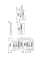
- control unit 60 that controls the driving of the flap drive motors 33a and 33b will be described.
- the control unit 60 is connected to various devices such as the indoor unit 10 and the outdoor unit 20, and performs cooling operation and heating based on an operation command from the air conditioning target person via the remote controller 80 or the like. It is possible to perform operation control of various devices according to each operation mode such as operation.
- the control unit 60 includes a flap drive control unit 61.
- the flap drive control unit 61 operates the state of the flap 30 by controlling the rotation speed and rotation direction of the flap drive motors 33a and 33b so that the flap drive mechanisms 30a and 30b are rotated or moved. Switch to the state appropriate for the mode. Specifically, the flap drive control unit 61 outputs control signals regarding the rotation speed and the rotation direction to the flap drive motors 33a and 33b. In the present embodiment, it is assumed that the flap drive control unit 61 does not individually control the flap drive motors 33a and 33b.
- the flap drive control unit 61 causes the drive shaft 35a, Flap drive motors 33a and 33b are controlled so that 35b and gears 38a and 38b rotate in the reverse direction Y2. For this reason, when the gears 38a and 38b rotate in the reverse direction Y2, the flap main body 31 rotates in the rotation direction X2 around the rotation shaft 32.
- the state of the flap 30 is switched from the first open state to the closed state.
- the flap drive control unit 61 causes the drive shafts 35a and 35b and The flap drive motors 33a and 33b are controlled so that the gears 38a and 38b rotate in the reverse direction Y2.
- the gears 38a and 38b rotate in the reverse direction Y2
- the flap body 31 moves in the movement direction X5.
- the flap body 31 moves in the movement direction X5
- the rotary shaft 32 moves from the first end portions 36aa, 36ba of the moving members 36a, 36b to the second end portions 36ab, 36bb.
- the state of the flap 30 is switched from the closed state to the rotation standby state.
- the flap drive control unit 61 is in the state of the gear 38a in a state where the rotary shaft 32 is at the positions of the second ends 36ab and 36bb of the moving members 36a and 36b.
- 38b further rotate in the reverse direction Y2 to control the flap drive motors 33a, 33b, whereby the flap body 31 rotates in the rotation direction X3 about the rotation shaft 32.
- the state of the flap 30 is switched from the closed state to the second open state through the rotation standby state.
- the flap drive control unit 61 causes the drive shafts 35a and 35b to be driven.
- the flap drive motors 33a and 33b are controlled so that the gears 38a and 38b rotate in the positive direction Y1.
- the gears 38a and 38b rotate in the forward direction Y1
- the flap body 31 rotates about the rotation shaft 32 in the rotation direction X4.
- the flap body 31 is rotated about the rotation shaft 32 in the rotation direction X4, whereby the state of the flap 30 is switched from the second open state to the rotation standby state. Furthermore, after the state of the flap 30 is switched to the rotation standby state, the flap drive control unit 61 controls the flap drive motors 33a and 33b so that the gears 38a and 38b further rotate in the positive direction Y1, The flap body 31 moves in the movement direction X6.
- the state of the flap 30 is switched from the second open state to the closed state through the rotation standby state.
- the state of the flap 30 is switched to the first open state or the second open state according to each operation mode.
- the position of the rotary shaft 32 with respect to the flap body 31 is moved.
- the flap body 31 moves in the moving direction only when the position of the rotary shaft 32 relative to the flap body 31 is moved by the flap drive motors 33a and 33b.
- the flap main body 31 rotates in the rotation direction only when the position of the rotary shaft 32 with respect to the flap main body 31 is rotated without being moved by the flap drive motors 33a and 33b.
- the flap drive control unit 61 first moves the flap body 31, that is, moves the position of the rotary shaft 32 relative to the flap body 31.
- the drive of the flap drive motors 33a and 33b is controlled to be performed, and the drive of the flap drive motors 33a and 33b is controlled so that the flap body 31 is rotated after the flap body 31 is moved.
- the flap drive control unit 61 first drives the flap drive motors 33a and 33b so that the flap body 31 is rotated.
- the flap drive control unit 61 controls the drive of the flap drive motors 33a and 33b so that the rotation of the flap body 31 and the movement of the flap body 31 are continuously performed. For this reason, the flap drive mechanisms 30a and 30b can continuously perform the rotation operation and the movement operation.
- the flap drive motors 33a and 33b are driven to perform the rotation operation and the movement operation by the flap drive mechanisms 30a and 30b. For this reason, compared with the case where the motor for rotating a rotating shaft in order to rotate a flap main body and the motor for moving the position of a rotating shaft are provided separately, the number of motors is reduced. can do. As a result, the number of parts can be reduced.
- the size of the flap body may be provided so as to be approximately the same as the opening area of the outlet from the viewpoint of design. In the case of such an indoor unit that does not include a rotating shaft moving mechanism, if the flap body is rotated as in the above embodiment, the flap body may interfere with the indoor unit casing.
- the size of the flap body 31 is less affected by the opening area of the outlet 15. Can do.
- the rotation shaft 32 when the rotation shaft 32 is positioned in the vicinity of the first ends 36aa, 36ba or the second ends 36ab, 36bb of the moving members 36a, 36b by the flap drive mechanisms 30a, 30b, the rotation is performed. The movement is performed. Further, the flap drive mechanisms 30a and 30b are configured not to perform the rotation operation when the movement operation is performed. For this reason, it is possible to prevent the rotation operation and the movement operation from being performed simultaneously. Thereby, the possibility that the flap main body 31 and the indoor unit casing 11 interfere with each other when the turning operation is performed can be reduced.
- the flap drive mechanisms 30a and 30b constitute a rack / pinion mechanism. Therefore, the driving force of the flap drive motors 33a and 33b can be transmitted to the flap body 31 via the gears 38a and 38b and the racks 39a and 39b.
- the rotation direction of the flap drive motors 33 a and 33 b is switched in the moving operation, so that the position of the rotary shaft 32 with respect to the flap main body 31 is moved, or the flap main body 31 is centered on the rotary shaft 32. It has been rotated. For this reason, the flap main body 31 can be rotated around the rotating shaft 32 or the rotating shaft 32 can be moved with an easy configuration.
- the flap drive mechanisms 30 a and 30 b are disposed in the vicinity of both end portions of the flap body 31. For this reason, for example, compared with the case where the flap drive mechanism is provided only in the vicinity of one end of the flap main body, it is possible to reduce the possibility that the rotating operation and the moving operation are not performed smoothly.
- the rotation shaft 32 includes the drive shaft 35a corresponding to the first flap drive mechanism 30a and the drive shaft 35b corresponding to the second flap drive mechanism 30b.
- the flap drive motors 33a and 33b include a first flap drive motor 33a for rotating the drive shaft 35a and a second flap drive motor 33b for rotating the drive shaft 35b. Therefore, a motor is provided to rotate the drive shafts 35a and 35b corresponding to the first flap drive mechanism 30a and the second flap drive mechanism 30b, respectively. Therefore, for example, the possibility that each drive shaft does not rotate can be reduced as compared with a case where a plurality of drive shafts corresponding to each of the plurality of flap drive mechanisms are rotated by one motor.
- the guide roller 40 configured to support the moving members 36 a and 36 b from the upper side and to rotate with the movement of the rotating shaft 32 is provided. For this reason, it is possible to prevent the flap body 31 from rotating during the movement of the flap body 31, that is, during the movement of the rotating shaft 32. Therefore, the possibility that the flap body 31 rotates during the movement of the flap body 31 can be reduced. Thereby, the rotating shaft 32 can be moved stably.
- the flap main body 31 and the indoor unit casing 11 interfere with each other during the moving operation can be reduced.
- the flap 30 when the cooling operation is performed, the flap 30 is in the first open state so that air is mainly blown out from the outlet 15 toward the front side of the indoor unit 10. Further, when the heating operation is performed, the flap 30 is in the second open state so that air is mainly blown out from the outlet 15 toward the lower side of the indoor unit 10. For this reason, the conditioned air can be guided to the front side of the indoor unit 10 during the cooling operation in which the temperature of the conditioned air is likely to be lower than the temperature of the room air. Further, the conditioned air can be guided to the lower side of the indoor unit 10 during the heating operation in which the temperature of the conditioned air is likely to be higher than the room temperature.
- the flap body when the cooling operation is performed in the air conditioner, the flap body is rotated so as to rotate within the first predetermined rotation range around the rotation axis positioned near the first end of the moving member.
- the flap body rotates within the second predetermined rotation range around the rotation axis located near the second end of the moving member.
- the flap drive motor may be controlled to do so.
- the inclination angle of the flap body with respect to the outlet is the rotation angle of the flap body, the rotation angle of the flap body when the flap is in the closed state is the fully closed angle, and the flap state is in the first open state.
- the rotation angle of the flap body in a certain case is defined as a first rotation angle
- the rotation angle of the flap body in the case where the flap state is in a rotation standby state is defined as a rotation standby angle
- the flap state is in a second open state.
- the first predetermined rotation range is the range from the fully closed angle to the first rotation angle
- the second predetermined rotation range is It is good also as a range from a rotation standby angle to a 2nd rotation angle.
- the flap drive control part 61 does not control each flap drive motor 33a, 33b separately.
- the flap drive control unit may be able to individually control each flap drive motor.
- the flap drive control unit can individually control each flap drive motor, for example, when the flap is rotated, the flap drive control unit The flap body is twisted by outputting a control signal to each flap drive motor so that the number of rotations is different or the direction of rotation of each flap drive motor is different. be able to. For this reason, the rotation angle at the both ends of the flap body with respect to the outlet can be adjusted.
- the rotational shaft position with respect to the flap body can be shifted at both ends of the flap body by setting the rotational speed of each flap drive motor to a different rotational speed.
- the flap drive control unit causes the flap drive so that only the drive shaft 135b is positioned in the vicinity of the second end 136bb of the moving member 136b (see FIG. 13).
- the flap main body 131 is disposed so that the left side of the flap main body 131 is displaced in the rearward direction of the indoor unit 110 with respect to the outlet 115, as shown in FIGS.
- the flap drive control unit can individually control the flap drive motors, the opening area of the air outlet that is opened by the flap body can be adjusted. Moreover, since the blowout port can be opened a little, an airflow having a high flow velocity can be blown out from the blowout port.
- the drive shaft 135a is located at the position shown in FIG. 13, that is, in the vicinity of the first end 136aa of the moving member 136a, and the drive shaft 135b is located at the position shown in FIG. 13, that is, the moving member 136b.
- the drive shaft 135a is located at the position shown in FIG. 13, that is, in the vicinity of the first end 136aa of the moving member 136a
- the drive shaft 135b is located at the position shown in FIG. 13, ie, the second position of the moving member 136b.
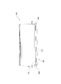
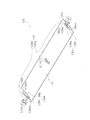
- FIG. 13 is a schematic perspective view of the flap 130 in a state where the drive shaft 135a is positioned near the first end 136aa of the moving member 136a and the drive shaft 135b is positioned near the second end 136bb of the moving member 136b.
- reference numeral 132 denotes a rotating shaft
- reference numeral 133a denotes a flap drive motor
- reference numeral 136ab denotes a second end portion
- reference numeral 136ba denotes a first shaft. End portions are shown
- reference numerals 138a and 138b indicate gears
- reference numerals 139a and 139b indicate racks.
- the flap drive motors 33a and 33b are disposed in the vicinity of both ends of the flap main body 31, respectively.
- a flap drive motor may be disposed only on one end side of the flap body.
- positioned only at the one end side of the flap main body 231 is demonstrated.
- the flap 230 mainly includes a flap body 231, one flap drive motor 233a, and flap drive mechanisms 230a and 230b.
- the flap body 231 is a plate-like member having a shape that is long in the longitudinal direction of the indoor unit. Further, the flap body 231 is connected to a rotation shaft 232 extending in the longitudinal direction h of the flap body 31 through meshing between gears 238a and 238b and racks 239a and 239b, which will be described later.
- the rotation shaft 232 includes a drive shaft 235a and a shaft 234 continuous with the drive shaft 235a.
- the drive shaft 235a is connected to the flap drive motor 233a, and rotates when the flap drive motor 233a is driven. Further, the shaft 234 rotates as the drive shaft 235a rotates.
- a support portion 237 for supporting the flap main body 231 is provided at the center of the flap main body 231. An opening 237 a into which the shaft 234 can be inserted is formed in the support portion 237.
- the flap drive motor 233a is a stepping motor that can rotate forward and backward, and is disposed on one end side of the flap body 231. Further, the flap drive motor 233a is connected to the drive shaft 235a as described above. For this reason, the flap drive motor 233a can rotate the rotating shaft 232. Note that the rotation direction and the number of rotations of the flap drive motor 233a are controlled by the control unit as in the above embodiment.
- the flap drive mechanisms 230a and 230b are a first flap drive mechanism 230a disposed near one end of the flap body 231 and a second flap drive mechanism 230b disposed near the other end of the flap body 231. It consists of and. Each flap drive mechanism 230a, 230b has moving members 236a, 236b and gears 238a, 238b, respectively.
- the moving members 236 a and 236 b are members that are long in a direction i orthogonal to the longitudinal direction h of the flap body 231, and are provided at both ends of the flap body 231 in the longitudinal direction h. Moreover, the moving members 236a and 236b have an oval shape in a side view and are fixed to the upper surface of the flap body 231.
- the moving members 236a and 236b are formed with long holes 237a and 237b for the gears 238a and 238b to enter. Each of the long holes 237a and 237b includes a circular arc surface portion at both ends, and an upper surface portion and a lower surface portion that connect the two circular arc surface portions.
- racks 239a and 239b that mesh with the gears 238a and 238b are formed on the upper surfaces of the long holes 237a and 237b.
- the gear 238a is fixed to the end of the drive shaft 235a.
- the gear 238b is connected to the end of the shaft 234. For this reason, each gear 238a, 238b rotates with rotation of the rotating shaft 232. In other words, when the flap drive motor 233a is driven, the gears 238a and 238b are rotated.
- the gears 238a and 238b mesh with racks 239a and 239b included in the moving members 236a and 236b. Therefore, the flap driving mechanisms 230a and 230b constitute a rack / pinion mechanism, and the driving force of the flap driving motor 233a can be transmitted to the flap body 231 via the gears 238a and 238b and the racks 239a and 239b. it can. With such a configuration, the flap driving mechanisms 230a and 230b cause the rotating shaft 232 to rotate by rotating the rotating shaft 232 by one flap driving motor 233a and transmitting power to the gears 238a and 238b and the racks 239a and 239b.
- Rotating operation for changing the inclination angle of the flap body 231 with respect to the outlet that is, the posture of the flap body 231, and moving operation for moving the flap body 231 in the front-rear direction of the indoor unit 210. (Equivalent to a position changing operation) can be performed. For this reason, compared with the case where a flap drive motor is arranged at both ends of the flap body, the number of motors for performing a rotating operation and a moving operation can be reduced, and the number of electric wires required for driving the motor can be reduced. The number can be reduced.
- the flap body 231 is provided with a support portion 237 in which an opening 237a into which the shaft 234 can be inserted is formed. For this reason, compared with the case where a support part is not provided, rotation of the flap main body 231 can be stabilized.
- the indoor unit 10 includes only one flap body 31, but may include a plurality of flap bodies. Further, when the indoor unit includes a plurality of flap main bodies, a mechanism similar to the flap driving mechanism of the present invention may be adopted for all the flap main bodies, and one part of the plurality of flap main bodies may be adopted. You may employ
- the rotating shaft 32 in the closed state, is located in 1st edge part 36aa, 36ba of the moving members 36a, 36b,
- the rotation shaft in the closed state, may be located at the second end of the moving member, or may be between the first end and the second end of the moving member. In such a case, a movement operation (transition operation to the rotation standby state) is performed when switching from the closed state to each open state as necessary.
- the present invention can reduce the number of parts by rotating the rotating shaft for rotating the flap and moving the position of the rotating shaft with the same motor, and thus can be applied to an indoor unit of an air conditioner. Is effective.
- Flap drive control unit 233a Flap drive motor (motor) 10, 110 Indoor unit 15, 115 Air outlet 30a, 130a, 230a First flap driving mechanism (flap moving mechanism) 30b, 130b, 230b Second flap drive mechanism (flap moving mechanism) 31, 131, 231 Flap body (Flap) 32, 132, 232 Rotating shaft 35a, 135a Drive shaft (first rotating shaft) 35b, 135b Drive shaft (second rotary shaft) 33a, 133a First flap drive motor (motor) 33b, 133b Second flap drive motor (motor) 38a, 38b, 138a, 138b, 238a, 238b Gear 39a, 39b, 139a, 139b, 239a, 239b Rack 40a, 40b Guide roller (rotation preventing member)
Landscapes
- Engineering & Computer Science (AREA)
- Chemical & Material Sciences (AREA)
- Combustion & Propulsion (AREA)
- Mechanical Engineering (AREA)
- General Engineering & Computer Science (AREA)
- Air-Flow Control Members (AREA)
- Air Conditioning Control Device (AREA)
- Air Filters, Heat-Exchange Apparatuses, And Housings Of Air-Conditioning Units (AREA)
Abstract
L'invention porte sur une unité intérieure (10) d'un climatiseur (1) qui est composée d'un corps de volet (31), de moteurs (33a, 33b) pour faire tourner un arbre rotatif (32), et de mécanismes d'entraînement de volet (30a, 30b). Le corps de volet (31) peut tourner autour de l'arbre rotatif (32) pour régler la direction de l'air soufflé à partir d'une sortie d'air (15). Les mécanismes d'entraînement de volet (30a, 30b) peuvent faire tourner l'arbre rotatif (32) de façon à effectuer une opération de rotation et une opération de changement de position. L'opération de rotation est une opération pour faire tourner le corps de volet (31) autour de l'arbre rotatif (32). De plus, l'opération de changement de position est une opération pour changer la position de l'arbre rotatif par rapport au corps de volet (31).
Applications Claiming Priority (2)
| Application Number | Priority Date | Filing Date | Title |
|---|---|---|---|
| JP2009-141246 | 2009-06-12 | ||
| JP2009141246A JP2010286194A (ja) | 2009-06-12 | 2009-06-12 | 空気調和機の室内機 |
Publications (1)
| Publication Number | Publication Date |
|---|---|
| WO2010143378A1 true WO2010143378A1 (fr) | 2010-12-16 |
Family
ID=43308641
Family Applications (1)
| Application Number | Title | Priority Date | Filing Date |
|---|---|---|---|
| PCT/JP2010/003704 Ceased WO2010143378A1 (fr) | 2009-06-12 | 2010-06-03 | Unité intérieure de climatiseur |
Country Status (2)
| Country | Link |
|---|---|
| JP (1) | JP2010286194A (fr) |
| WO (1) | WO2010143378A1 (fr) |
Cited By (5)
| Publication number | Priority date | Publication date | Assignee | Title |
|---|---|---|---|---|
| EP2848872A1 (fr) * | 2013-09-17 | 2015-03-18 | Samsung Electronics Co., Ltd | Climatiseur |
| EP2937641A4 (fr) * | 2012-12-19 | 2016-12-07 | Mitsubishi Electric Corp | Climatiseur |
| WO2017133438A1 (fr) * | 2016-02-01 | 2017-08-10 | 珠海格力电器股份有限公司 | Unité intérieure de climatiseur, et climatiseur la comprenant |
| WO2018196770A1 (fr) * | 2017-04-26 | 2018-11-01 | 珠海格力电器股份有限公司 | Climatiseur |
| US11299009B2 (en) | 2020-03-10 | 2022-04-12 | Denso International America, Inc. | Vehicle HVAC system with modular door design |
Families Citing this family (2)
| Publication number | Priority date | Publication date | Assignee | Title |
|---|---|---|---|---|
| CN103939985B (zh) * | 2014-03-31 | 2016-09-07 | 美的集团股份有限公司 | 空调器室内机 |
| CN108061369B (zh) * | 2017-12-08 | 2020-07-14 | Tcl空调器(中山)有限公司 | 自动摆风结构及空调器 |
Citations (9)
| Publication number | Priority date | Publication date | Assignee | Title |
|---|---|---|---|---|
| JPH10160234A (ja) * | 1996-11-26 | 1998-06-19 | Daikin Ind Ltd | 水平フラップの回転機構 |
| JPH10318597A (ja) * | 1997-05-20 | 1998-12-04 | Fujitsu General Ltd | 空気調和機 |
| JP2001215043A (ja) * | 2000-02-03 | 2001-08-10 | Daikin Ind Ltd | 空気調和機 |
| JP2003232297A (ja) * | 2002-02-08 | 2003-08-22 | Sharp Corp | 送風装置 |
| JP2006162216A (ja) * | 2004-12-10 | 2006-06-22 | Sharp Corp | 空気調和機 |
| JP2007155128A (ja) * | 2005-11-08 | 2007-06-21 | Nidec Sankyo Corp | モータアクチュエータ |
| JP2008190809A (ja) * | 2007-02-07 | 2008-08-21 | Hitachi Appliances Inc | 空気調和機 |
| JP2009052831A (ja) * | 2007-08-28 | 2009-03-12 | Mitsubishi Electric Corp | 空気調和機 |
| JP2009052834A (ja) * | 2007-08-28 | 2009-03-12 | Mitsubishi Electric Corp | 空気調和機 |
-
2009
- 2009-06-12 JP JP2009141246A patent/JP2010286194A/ja active Pending
-
2010
- 2010-06-03 WO PCT/JP2010/003704 patent/WO2010143378A1/fr not_active Ceased
Patent Citations (9)
| Publication number | Priority date | Publication date | Assignee | Title |
|---|---|---|---|---|
| JPH10160234A (ja) * | 1996-11-26 | 1998-06-19 | Daikin Ind Ltd | 水平フラップの回転機構 |
| JPH10318597A (ja) * | 1997-05-20 | 1998-12-04 | Fujitsu General Ltd | 空気調和機 |
| JP2001215043A (ja) * | 2000-02-03 | 2001-08-10 | Daikin Ind Ltd | 空気調和機 |
| JP2003232297A (ja) * | 2002-02-08 | 2003-08-22 | Sharp Corp | 送風装置 |
| JP2006162216A (ja) * | 2004-12-10 | 2006-06-22 | Sharp Corp | 空気調和機 |
| JP2007155128A (ja) * | 2005-11-08 | 2007-06-21 | Nidec Sankyo Corp | モータアクチュエータ |
| JP2008190809A (ja) * | 2007-02-07 | 2008-08-21 | Hitachi Appliances Inc | 空気調和機 |
| JP2009052831A (ja) * | 2007-08-28 | 2009-03-12 | Mitsubishi Electric Corp | 空気調和機 |
| JP2009052834A (ja) * | 2007-08-28 | 2009-03-12 | Mitsubishi Electric Corp | 空気調和機 |
Cited By (10)
| Publication number | Priority date | Publication date | Assignee | Title |
|---|---|---|---|---|
| EP2937641A4 (fr) * | 2012-12-19 | 2016-12-07 | Mitsubishi Electric Corp | Climatiseur |
| US9696051B2 (en) | 2012-12-19 | 2017-07-04 | Mitsubishi Electric Corporation | Air conditioner |
| EP2848872A1 (fr) * | 2013-09-17 | 2015-03-18 | Samsung Electronics Co., Ltd | Climatiseur |
| US20150075201A1 (en) * | 2013-09-17 | 2015-03-19 | Samsung Electronics Co., Ltd. | Air conditioner |
| CN104456899A (zh) * | 2013-09-17 | 2015-03-25 | 三星电子株式会社 | 空调 |
| CN104456899B (zh) * | 2013-09-17 | 2019-06-25 | 三星电子株式会社 | 空调 |
| US10393422B2 (en) | 2013-09-17 | 2019-08-27 | Samsung Electronics Co., Ltd. | Air conditioner |
| WO2017133438A1 (fr) * | 2016-02-01 | 2017-08-10 | 珠海格力电器股份有限公司 | Unité intérieure de climatiseur, et climatiseur la comprenant |
| WO2018196770A1 (fr) * | 2017-04-26 | 2018-11-01 | 珠海格力电器股份有限公司 | Climatiseur |
| US11299009B2 (en) | 2020-03-10 | 2022-04-12 | Denso International America, Inc. | Vehicle HVAC system with modular door design |
Also Published As
| Publication number | Publication date |
|---|---|
| JP2010286194A (ja) | 2010-12-24 |
Similar Documents
| Publication | Publication Date | Title |
|---|---|---|
| CN102472521B (zh) | 空调机的室内机 | |
| JP6223953B2 (ja) | 空気調和機 | |
| JP2010286194A (ja) | 空気調和機の室内機 | |
| CN113623850B (zh) | 壁挂式空调室内机 | |
| JP2009019831A (ja) | 空気調和機 | |
| WO2006006623A1 (fr) | Condensateur intérieur pour climatiseur | |
| JP5519232B2 (ja) | 空気調和装置 | |
| JP4844665B2 (ja) | 空気調和装置 | |
| JP4766161B2 (ja) | 空気調和機の室内機 | |
| JP4656257B1 (ja) | 空気調和装置 | |
| JP3792032B2 (ja) | 空気調和機の風向調節装置 | |
| WO2006006622A1 (fr) | Condensateur intérieur de climatiseur | |
| JP4339825B2 (ja) | 空気調和機の室内機 | |
| JP5232497B2 (ja) | 空調用室内ユニット | |
| JP5240249B2 (ja) | 空気調和機 | |
| JP7328816B2 (ja) | 空気調和機の室内機及び空気調和機 | |
| CN105202728A (zh) | 一种导风槽组件及空调器 | |
| JP4684213B2 (ja) | 空気調和機の室内機 | |
| JP7022290B1 (ja) | 床置き型空気調和機 | |
| WO2011007522A1 (fr) | Climatiseur | |
| JP2011012926A (ja) | 空気調和機 | |
| JP3801190B2 (ja) | 空気調和機の室内機 | |
| JP2011094877A (ja) | 空気調和装置の室内機 | |
| CN114183816B (zh) | 室内机及具有其的空调器 | |
| CN109556269A (zh) | 一种侧端导风装置及空调器 |
Legal Events
| Date | Code | Title | Description |
|---|---|---|---|
| 121 | Ep: the epo has been informed by wipo that ep was designated in this application |
Ref document number: 10785910 Country of ref document: EP Kind code of ref document: A1 |
|
| NENP | Non-entry into the national phase |
Ref country code: DE |
|
| 122 | Ep: pct application non-entry in european phase |
Ref document number: 10785910 Country of ref document: EP Kind code of ref document: A1 |