WO2010143426A1 - Système d'analyse de masse de type séparateur cyclone - Google Patents
Système d'analyse de masse de type séparateur cyclone Download PDFInfo
- Publication number
- WO2010143426A1 WO2010143426A1 PCT/JP2010/003853 JP2010003853W WO2010143426A1 WO 2010143426 A1 WO2010143426 A1 WO 2010143426A1 JP 2010003853 W JP2010003853 W JP 2010003853W WO 2010143426 A1 WO2010143426 A1 WO 2010143426A1
- Authority
- WO
- WIPO (PCT)
- Prior art keywords
- gas
- swirl
- cyclone separator
- mass
- generating container
- Prior art date
- Legal status (The legal status is an assumption and is not a legal conclusion. Google has not performed a legal analysis and makes no representation as to the accuracy of the status listed.)
- Ceased
Links
Images





Classifications
-
- G—PHYSICS
- G01—MEASURING; TESTING
- G01N—INVESTIGATING OR ANALYSING MATERIALS BY DETERMINING THEIR CHEMICAL OR PHYSICAL PROPERTIES
- G01N1/00—Sampling; Preparing specimens for investigation
- G01N1/28—Preparing specimens for investigation including physical details of (bio-)chemical methods covered elsewhere, e.g. G01N33/50, C12Q
- G01N1/34—Purifying; Cleaning
-
- H—ELECTRICITY
- H01—ELECTRIC ELEMENTS
- H01J—ELECTRIC DISCHARGE TUBES OR DISCHARGE LAMPS
- H01J49/00—Particle spectrometers or separator tubes
- H01J49/02—Details
- H01J49/04—Arrangements for introducing or extracting samples to be analysed, e.g. vacuum locks; Arrangements for external adjustment of electron- or ion-optical components
- H01J49/0422—Arrangements for introducing or extracting samples to be analysed, e.g. vacuum locks; Arrangements for external adjustment of electron- or ion-optical components for gaseous samples
-
- G—PHYSICS
- G01—MEASURING; TESTING
- G01N—INVESTIGATING OR ANALYSING MATERIALS BY DETERMINING THEIR CHEMICAL OR PHYSICAL PROPERTIES
- G01N1/00—Sampling; Preparing specimens for investigation
- G01N1/02—Devices for withdrawing samples
- G01N1/22—Devices for withdrawing samples in the gaseous state
- G01N1/2202—Devices for withdrawing samples in the gaseous state involving separation of sample components during sampling
- G01N1/2211—Devices for withdrawing samples in the gaseous state involving separation of sample components during sampling with cyclones
-
- H—ELECTRICITY
- H01—ELECTRIC ELEMENTS
- H01J—ELECTRIC DISCHARGE TUBES OR DISCHARGE LAMPS
- H01J49/00—Particle spectrometers or separator tubes
- H01J49/02—Details
- H01J49/10—Ion sources; Ion guns
- H01J49/16—Ion sources; Ion guns using surface ionisation, e.g. field-, thermionic- or photo-emission
- H01J49/168—Ion sources; Ion guns using surface ionisation, e.g. field-, thermionic- or photo-emission field ionisation, e.g. corona discharge
Definitions
- the present invention relates to a cyclone separator mass spectrometry system capable of removing dust from a gas containing dust and performing mass spectrometry in a vacuum system.
- Mass spectrometers are known as devices for analyzing gases, liquids and solids.
- a mass spectrometer for analyzing a gas one using a vacuum system is known. If a mass spectrometer for gas analysis is used, a substance contained in a target gas can be analyzed.
- mass spectrometers must maintain a high degree of vacuum. For this reason, when the atmosphere is directly introduced into the mass spectrometer, the analysis accuracy is deteriorated and the inside of the vacuum apparatus is further contaminated.
- Patent Document 1 discloses a particle mass spectrometry method.
- Patent Document 2 discloses a particle mass spectrometer.
- the particle mass spectrometers disclosed in these documents introduce an aerosol through an aerosol intake tube, and a gas in which a plurality of types of particles are suspended is separated for each particle having a specific mass (particle mass / charge) within a predetermined range. Classify and obtain the particle mass distribution on it.
- an object of the present invention is to provide a mass spectrometry system that can analyze an analysis target system under atmospheric pressure and is small in size.
- the present invention is basically based on the knowledge that, by combining a mass spectrometer with a cyclone separator, dust can be removed and a gas with a sufficiently reduced pressure can be introduced into the mass spectrometer.
- dust can be removed and a gas with a sufficiently reduced pressure can be introduced into the mass spectrometer.
- the atmosphere can be adjusted to a situation where it can be directly introduced into the mass spectrometer.
- the first aspect of the present invention includes a cyclone separator 1, an analyzer inlet 3 attached to the cyclone separator 1, and a mass spectrometer 5 connected to the cyclone separator 1 via the analyzer inlet 3. It relates to the mass spectrometry system 7.
- the cyclone separator 1 is attached to the swirl generation container 9, the intake port 11 for taking gas into the swirl generation container 9, and the swirl of the gas taken into the swirl generation container 9. And an exhaust port 15 for exhausting the gas separated into the swirl of the gas taken into the swirl generating container 9.
- the mass spectrometer 5 has a vacuum system.
- the turning generator 13 includes a turbo blade 17 and a hollow motor 19 that rotationally drives the turbo blade 17.
- the turbo blade 17 is provided so that the rotation center of the turbo blade 17 is on the same axis as the analyzer introduction port 3.
- the atmospheric pressure can be adjusted so that it can be directly introduced into the mass spectrometer 5. That is, by adopting such a configuration, the mass spectrometric system of the present invention can introduce gas into which the dust is removed and the pressure is sufficiently reduced, to the mass spectroscope 5.
- the second aspect of the present invention relates to a method for analyzing a substance contained in a gas.
- the cyclone separator 1 swirls and separates the gas contained in the gas, the step of introducing the swirled and separated gas into the mass spectrometer 5, and the substance contained in the gas introduced into the mass spectrometer 5 Analyzing the mass of the.
- the gas contained in the gas is placed in a swirling gas by placing an ion source portion that can be ionized under atmospheric pressure, such as electrospray or discharge ionization, while swirling the gas contained in the gas. It includes a step of ionizing and collecting the ionized gas at the center of the cyclone separator 1.
- the step of introducing the swirl-separated gas into the mass spectrometer 5 is a gas whose pressure has been lowered by the swirl-separation step, and the ionized gas collected in the center of the cyclone separator 1 is This is a process to be introduced into the analyzer 5.
- FIG. 1 is a schematic diagram showing the configuration of the mass spectrometry system of the present invention.
- FIG. 2 is a diagram showing an example of the turbo blade of the present invention.
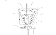
- FIG. 3 is a schematic diagram showing a mass spectrometry system having an ionization unit and a guide wire.
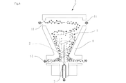
- FIG. 4 is a conceptual diagram showing the operation of the mass spectrometry system of the present invention.
- FIG. 5 is a diagram illustrating an example of a cyclone separator and an analyzer inlet. 5A is a front perspective view, FIG. 5B is a bottom perspective view, and FIG. 5C is an exploded view.
- FIG. 6 is a schematic diagram showing a mass spectrometry system having an ionization unit and a guide wire.
- FIG. 6 is a schematic diagram showing a mass spectrometry system having an ionization unit and a guide wire.
- FIG. 7 is a schematic diagram showing a mass spectrometry system using an electrospray method as an ionization method.
- FIG. 8 is a schematic diagram of a mass spectrometry system having a discharge part in a swirl generating container.
- FIG. 9 is a diagram for explaining the mass spectrometry system according to the fifth embodiment.
- FIG. 1 is a schematic diagram showing the configuration of the mass spectrometry system of the present invention.
- the mass spectrometry system of the present invention includes a cyclone separator 1, an analyzer introduction port 3, and a mass spectrometer 5.
- the cyclone separator 1 and the mass spectroscope 5 are connected via the analyzer introduction port 3 attached to the cyclone separator 1.
- the cyclone separator 1 includes a swirl generating container 9, an intake port 11, a swirl generating device 13, and an exhaust port 15.
- the swirl generating container 9 is a container in which gas swirls. When there is a liquid or solid in the swirl generating container 9, the swirl generating container 9 may be swirled together. As the swirl generating container 9, the one used for the cyclone separator can be used. As shown in FIG. 1, the specific swirl generating container 9 has an inverted frustoconical inner wall that decreases in diameter as it proceeds downward.
- the swirl generating container 9 can be made of the same material as the vacuum chamber. Note that the swirl generating container 9 is preferably sealed by a lid.
- the intake port 11 is attached to the swirl generating container 9 so that gas can be taken into the swirl generating container 9.
- the intake port 11 is preferably provided in the upper part of the swirl generating container 9.
- One intake port 11 may be attached to the swirl generating container 9, or two or more intake ports 11 may be provided.
- the intake ports 11 are installed at positions that are symmetrical via the swirl generating container 9.
- a filter may be appropriately provided in the intake portion of the intake port 11. Since the intake port 11 has a filter, relatively large dust can be removed. As a result, it is possible to prevent a large object or an organism (for example, an insect) from entering the swivel generation container 9.
- the air inlet 11 may be a pipe having a circular cross section. In that case, the diameter of the cross section is 1 cm or more and 10 cm or less.
- the swirl generator 13 is a means for swirling the gas taken into the swirl generating container 9. In addition, when there exists a liquid and a solid in the rotation generation container 9, they may be rotated together.
- the turning generator 13 includes a turbo blade 17 and a hollow motor 19 that rotationally drives the turbo blade 17.
- the turbo blade 17 is provided so that the rotation center of the turbo blade 17 is on the same axis as the analyzer introduction port 3.
- the turbo blade 17 is already known as disclosed in Japanese Patent No. 3637021.
- FIG. 2 is a diagram showing an example of the turbo blade of the present invention. As shown in FIG. 2, the turbo blade 17 of the present invention has a disk-shaped rotating substrate 31 and a plurality of wings 33 provided on the rotating substrate 31.
- the plurality of wings are provided symmetrically with respect to the center of the rotating substrate.
- the plurality of wings are not radial but curved in a predetermined direction.
- the plurality of wings include a portion in which the height from the substrate becomes higher as it approaches the center of the rotating substrate. Since the turbo blade 17 has such a shape, a spiral airflow can be effectively generated in the swirl generating container 9.
- the turbo blade 17 of the present invention preferably has a hole in the center of the substrate. And it is preferable that the analyzer inlet 3 is installed in the hole of the substrate having the hole.
- the hollow motor 19 is a motor having a hollow through hole.
- the analyzer introduction port 3 is installed in the through hole.
- An example of the through hole has a diameter of 0.1 mm to 10 mm, and may be 0.4 mm to 2 mm.
- An example of the rotation speed of the hollow motor 19 is 40,000 rpm or more.
- the exhaust port 15 is a part for exhausting the swirled and separated gas out of the gas taken into the swirl generating container 9. If there are liquids or solids in the swirl generating container 9, the exhaust port 15 is for discharging them. That is, the exhaust port functions as a discharge port.
- the analyzer introduction port 3 is a part for connecting the cyclone separator 1 and the mass spectrometer 5.
- An example of the analyzer inlet 3 is a gas pipe having an orifice. The analyzer inlet 3 only needs to be able to introduce the gas in the cyclone separator into the mass analyzer 5 through the hole provided in the center of the substrate of the turbo blade 17 and the through hole of the hollow motor 19. .
- the mass spectrometer 5 of the present invention is a mass spectrometer having a vacuum system.
- the present invention can use various mass spectrometers already known as mass spectrometers. Examples of mass spectrometers are a time-of-flight type, an ion trap type, a quadrupole type, an FT-ICR type, a magnetic field type, and an IMS (ion mobility) type.
- the present invention can particularly preferably use a time-of-flight mass spectrometer.
- the inside of the chamber is maintained at a high vacuum. For this reason, it is difficult to directly analyze the gas contained in the atmosphere.
- dust is removed by using the cyclone separator 1 and the portion where the pressure is lowered at the center of gas rotation is introduced into the mass spectrometer 5, so that the gas under atmospheric pressure can be obtained despite the simple apparatus. Can be introduced, and further component analysis can be performed.
- a preferable example of the mass spectrometer is a mass spectrometer disclosed in Japanese Patent No. 4208744, Japanese Patent Application Laid-Open No. 2005-79049, or Japanese Patent Application Laid-Open No. 11-135060.
- An example of a mass spectrometer is a “time-of-flight mass spectrometer in which an incident trajectory for implanting ions and an exit trajectory for extracting ions are provided in a closed trajectory constituted by a plurality of sector electric fields”.
- a normal time-of-flight mass spectrometer includes a plurality of vacuum chambers and a plurality of pumps, and has a size of 1 m or more. Therefore, time-of-flight mass spectrometers are usually installed in laboratories.
- the time-of-flight mass spectrometer disclosed in the above publication can be miniaturized so as to be portable. Therefore, it can be used as a portable mass analysis system by combining with the mass analysis system of the present invention. This eliminates the need to collect gas and analyze it in the laboratory. More specifically, for example, by bringing the mass spectrometry system of the present invention to an observation point, the local atmosphere can be analyzed in real time.
- FIG. 3 is a schematic diagram showing a mass spectrometry system having an ionization section and a guide wire.
- the mass spectrometry system 7 includes an ionization unit 21 and a guide wire 23.
- the ionization unit 21 is provided in the swirl generation container 9 and is for ionizing the gas taken into the swirl generation container 9.
- any known one can be used as long as it can ionize the gas taken into the swirl generating container 9.
- Specific examples of ionization methods are atmospheric pressure ionization, electrospray ionization, fast atom bombardment, electron ionization, chemical ionization, electrolytic desorption ionization, and electrolytic ionization.
- an atmospheric pressure ionization method or an electrospray ionization method is preferable as the ionization method.
- the guide wire 23 is provided in the swirl generating container 9 so as to be on the same axis as the analyzer introduction port 3, and is used to draw the gas ionized by the ionization unit 21. Therefore, the guide wire 23 is preferably charged.
- the mass spectrometry system 7 preferably has a voltage source for applying a potential to the guide wire 23.
- Another preferred embodiment of the mass spectrometry system 7 is one having a discharge part 25 in the swirl generating container 9.
- FIG. 4 is a conceptual diagram showing the operation of the mass spectrometry system of the present invention.
- the mass spectrometry system 7 of the present invention can be used in a method for analyzing a substance contained in a gas. Then, a step of rotating and separating the gas contained in the gas by the cyclone separator 1, a step of introducing the swirled and separated gas into the mass analyzer 5, and the mass of the substance contained in the gas introduced into the mass analyzer 5 Analyzing.
- the process of turning and separating the gas contained in the gas by the cyclone separator 1 will be described.
- An example of a gas is the atmosphere.
- the gas in this specification may contain not only gas but solids, such as fine powder, like air
- the turbo blade 17 rotates, and a spiral airflow is generated as shown in FIG.
- gas is introduced into the swirl generating container 9 from the intake port 11.
- the introduced gas advances downward while making a swivel motion.
- heavy materials are subjected to a large turning motion because they receive a strong centrifugal force.
- light materials do not receive strong centrifugal force, so they perform a relatively small turning motion.
- the heavy substance is separated to the outside by the centrifugal force, and the light substance is separated to the inside of the heavy substance.
- the gas is centrifuged by specific gravity.
- the gas having a high specific gravity is guided to the exhaust port 15 and exhausted.
- the swirl motion becomes intense.
- a reduced pressure region is generated at the lower center portion of the cyclone separator 1. That is, the gas having a low specific gravity is collected at the center of the cyclone separator 1 by the swirl separation process, and the pressure is lowered.
- Reference numeral 2 in the figure indicates a reduced pressure region.
- the mass spectrometric system 7 of the present invention uses the cyclone separator 1 so that a reduced pressure region 2 is generated at the center thereof. In particular, the portion on the mass spectrometer side in the reduced pressure region 2 is in a low vacuum state.
- the mass spectrometry system 7 including the ionization unit 21 and the guide wire 23 ionizes the gas contained in the swirl generation container 9.
- a charge opposite to the charge charged by ionization is applied to the guide wire 23.
- the guide wire 23 is positively charged. Then, the ionized gas is attracted to the guide wire 23 and collected near the center of the cyclone separator 1.
- the step of introducing the swirl-separated gas into the mass spectrometer 5 is a gas whose pressure has been lowered by the swirl-separation step, and the ionized gas collected in the center of the cyclone separator 1 is This is a process to be introduced into the analyzer 5. That is, since the center of the turbo blade 17 and the hollow motor 19 is hollow and exists on the concentric axis with the center of gas rotation, the gas whose dust has been removed and reduced in pressure can be introduced into the mass spectrometer 5. it can.
- the analyzer introduction port 3 may be provided on the intake port 11 side.
- molecules (including excited molecules) or ions are released from the downstream region.
- region, and the gas taken in from the inlet port 11 and carried out rotation interaction interact. Then, the reacted gas after the interaction is taken in from the analyzer inlet 3.
- this emitting part is a DART (DirectTAnization TinTReal Time) ion source.
- DART DirectTAnization TinTReal Time
- Such a DART (registered trademark) ion source is disclosed, for example, in JP-T-2006-523367, US Pat. No. 6,949,741, and JP-A-2007-256246. The contents of these documents are incorporated herein in their entirety by reference.
- the DART method is an atmospheric pressure ionization method using excited gas molecules (atoms) having no charge.
- excited molecules generated by corona discharge or glow discharge are reacted with a sample under atmospheric pressure, the sample is ionized, and introduced into an ion inlet (orifice) of a mass spectrometer.
- the pressure is not atmospheric pressure but reduced pressure.
- the preferred mass spectrometry system of the present invention has a decompression mechanism for decompressing the inside of the ion source or swirl generating container 9.
- An example of the pressure reducing mechanism is a pump.
- Examples of the pressure as a result of depressurization are 0.1 atm or more and 0.9 atm or less, and 0.2 atm or more and 0.5 atm or less.
- the reaction proceeds under reduced pressure.
- an inexpensive gas such as nitrogen gas can be used as an alternative gas.
- Example 1 relates to a mass spectrometry system for analyzing components contained in the atmosphere.
- FIG. 5 is a diagram illustrating an example of a cyclone separator and an analyzer inlet.
- 5A is a front perspective view
- FIG. 5B is a bottom perspective view
- FIG. 5C is an exploded view.
- the cyclone separator 1 includes a swirl generating container 9, an intake port 11, a swirl generating device 13 (a turbo blade 17 and a hollow motor 19), and an exhaust port 15 (dust exhaust port).
- the hollow motor 19 is fixed to the swirl generating container 9 by a connecting flange.
- the analyzer introduction port 3 has a tapered tip at the swirl generating container 9 side to form an orifice.
- FIG. 5 the mass spectrometer is omitted.
- the cyclone separator 1 and the analyzer inlet 3 shown in FIG. 5 are connected to a mass analyzer and constitute a mass analyzer system 7.
- reference numeral 35 denotes a connecting flange
- reference numeral 37 denotes a fixing screw.
- Example 2 relates to a mass spectrometry system having an ionization unit and a guide wire.
- FIG. 6 is a schematic diagram showing a mass spectrometry system having an ionization unit and a guide wire.
- the guide wire is a wire made of a conductive material.
- the gas introduced into the swirl generating container 9 by the atmospheric pressure ionization method is ionized so as to be, for example, negative ions.
- the inner wall 39 of the swirl generating container 9 is a high resistance body. A voltage is applied to the inner wall and the guide wire 23. Then, a potential difference is generated between the inner wall and the guide wire 23. As a result, an electric field is generated in the swirl generating container 9.
- Example 3 relates to a mass spectrometry system using an electrospray method as an ionization method.
- FIG. 7 is a schematic diagram showing a mass spectrometry system using an electrospray method as an ionization method.
- nitrogen gas is introduced from the intake port 11 into the swirl generating container 9.
- the substance to be analyzed is sprayed as a solution using the introduced nitrogen gas.
- a Coulomb explosion is triggered and ions are generated.
- the droplets are swirled by the air flow in the swirl generating container 9. Then, the droplets are actively dried. Large droplets that do not become ions are centrifuged and guided to the exhaust port 15.
- the degree of vacuum of the mass spectrometer 5 cannot be maintained, and the inside of the mass spectrometer is contaminated.
- only gasified and ionized materials can be introduced into the mass spectrometer, so that the burden on the vacuum system can be reduced.
- the ionized gas can be collected in the vicinity of the guide wire 23, and the selection efficiency can be increased.
- Example 4 relates to a mass spectrometry system having a discharge unit 25 in a swirl generating container 9.
- FIG. 8 is a schematic diagram of a mass spectrometry system having a discharge part in a swirl generating container.
- the example of this system has a discharge probe as the discharge unit 25. Discharge the discharge probe to excite the inert gas. The excited inert gas collides with the target substance. Then, electric charges are exchanged between the inert gas and the substance to be analyzed. The generated ions are much smaller in mass than dust. Therefore, the generated ions travel downward while turning around the center, and are guided from the center of the turbo blade 17 to the mass spectrometer 5 through the orifice.
- Example 5 relates to a mass spectrometry system in which the analyzer introduction port 3 is located not in the downstream region of the molecular flow from the intake port 11 but in the upstream region.
- the mass spectrometric system further includes a discharge unit 27 for discharging molecules or ions from the swirl generator 13 side in the swirl generation container 9. More specifically, this mass spectrometry system has a discharge part 27 that passes through the rotation axis of the swivel generator 13. Examples of the discharge part 27 are an electrospray and a spray needle. Then, ions and molecules (including excited molecules) are sprayed or emitted along the central axis of the hollow motor constituting the swirl generator 13. In this case, the analyzer introduction port 3 is provided at a position facing the discharge unit 27. *
- the mass spectrometry system of the present invention can be effectively used in the field related to analytical instruments.
Landscapes
- Chemical & Material Sciences (AREA)
- Life Sciences & Earth Sciences (AREA)
- Analytical Chemistry (AREA)
- Health & Medical Sciences (AREA)
- Biomedical Technology (AREA)
- Physics & Mathematics (AREA)
- Molecular Biology (AREA)
- Engineering & Computer Science (AREA)
- Biochemistry (AREA)
- General Health & Medical Sciences (AREA)
- General Physics & Mathematics (AREA)
- Immunology (AREA)
- Pathology (AREA)
- Other Investigation Or Analysis Of Materials By Electrical Means (AREA)
- Electron Tubes For Measurement (AREA)
Abstract
Priority Applications (2)
| Application Number | Priority Date | Filing Date | Title |
|---|---|---|---|
| JP2011518308A JP5435667B2 (ja) | 2009-06-10 | 2010-06-09 | サイクロンセパレータ式質量分析システム |
| US13/376,840 US8410435B2 (en) | 2009-06-10 | 2010-06-09 | Cyclone separator type mass analyzing system |
Applications Claiming Priority (2)
| Application Number | Priority Date | Filing Date | Title |
|---|---|---|---|
| JP2009-138922 | 2009-06-10 | ||
| JP2009138922 | 2009-06-10 |
Publications (1)
| Publication Number | Publication Date |
|---|---|
| WO2010143426A1 true WO2010143426A1 (fr) | 2010-12-16 |
Family
ID=43308689
Family Applications (1)
| Application Number | Title | Priority Date | Filing Date |
|---|---|---|---|
| PCT/JP2010/003853 Ceased WO2010143426A1 (fr) | 2009-06-10 | 2010-06-09 | Système d'analyse de masse de type séparateur cyclone |
Country Status (3)
| Country | Link |
|---|---|
| US (1) | US8410435B2 (fr) |
| JP (1) | JP5435667B2 (fr) |
| WO (1) | WO2010143426A1 (fr) |
Cited By (2)
| Publication number | Priority date | Publication date | Assignee | Title |
|---|---|---|---|---|
| KR20180061225A (ko) * | 2015-09-30 | 2018-06-07 | 스미스 디텍션-워트포드 리미티드 | 가스 유체 샘플링 장치 및 방법 |
| JP2018535401A (ja) * | 2015-09-30 | 2018-11-29 | スミスズ ディテクション−ワトフォード リミテッド | サンプリング装置及び方法 |
Families Citing this family (3)
| Publication number | Priority date | Publication date | Assignee | Title |
|---|---|---|---|---|
| CN110702434A (zh) * | 2018-07-10 | 2020-01-17 | 中国石油天然气股份有限公司 | 旋风子实验系统及实验方法 |
| US11577258B2 (en) | 2019-11-05 | 2023-02-14 | The Johns Hopkins University | Cyclone and methods of manufacture thereof |
| US11862447B2 (en) | 2022-03-01 | 2024-01-02 | Arrowhead Center, Inc. | Apparatus and method for agricultural contaminant detection |
Citations (6)
| Publication number | Priority date | Publication date | Assignee | Title |
|---|---|---|---|---|
| JPS58223737A (ja) * | 1982-06-23 | 1983-12-26 | Sankyo Dengiyou Kk | サンプリング管 |
| JPH07294393A (ja) * | 1994-04-28 | 1995-11-10 | Yokogawa Electric Corp | ダストサンプラー |
| JPH09145568A (ja) * | 1995-11-29 | 1997-06-06 | Matsushita Electric Works Ltd | Ipc分析方法 |
| JP2000214149A (ja) * | 1999-01-28 | 2000-08-04 | Shimadzu Corp | 液体クロマトグラフ質量分析装置 |
| JP2001183284A (ja) * | 1999-12-24 | 2001-07-06 | Nippon Telegr & Teleph Corp <Ntt> | 花粉分別方法及び装置並びに花粉飛散数計測方法及び装置 |
| JP2002543975A (ja) * | 1999-05-15 | 2002-12-24 | グラスビー ダイナミクス リミテッド | 分析対象物質の分離および捕集 |
Family Cites Families (8)
| Publication number | Priority date | Publication date | Assignee | Title |
|---|---|---|---|---|
| DE2518201C3 (de) * | 1975-04-24 | 1979-03-15 | Battelle-Institut E.V., 6000 Frankfurt | Vorrichtung zum Trennen von Gasgemischen in Bestandteile unterschiedlicher Molekülmassen |
| US4092130A (en) * | 1976-02-04 | 1978-05-30 | Wikdahl Nils Anders Lennart | Process for the separation of gas mixtures into component fractions according to their molecular or atomic weight |
| JP2517872B2 (ja) | 1993-08-16 | 1996-07-24 | 工業技術院長 | エアロゾル粒子質量分析方法 |
| JP3663975B2 (ja) * | 1998-08-25 | 2005-06-22 | 株式会社日立製作所 | 排ガスモニタ装置 |
| JP2006150167A (ja) * | 2004-11-25 | 2006-06-15 | Dai-Dan Co Ltd | イオン化分離装置 |
| JP2007171064A (ja) * | 2005-12-26 | 2007-07-05 | Nippon Steel Corp | ガス分析用Jet−REMPI装置 |
| EP2089128A4 (fr) * | 2006-12-08 | 2013-04-17 | Spectra Analysis Instr Inc | Procédé et appareil permettant de désolvater un liquide en circulation |
| JP4822278B2 (ja) | 2007-03-08 | 2011-11-24 | 独立行政法人産業技術総合研究所 | 粒子質量分析方法 |
-
2010
- 2010-06-09 JP JP2011518308A patent/JP5435667B2/ja not_active Expired - Fee Related
- 2010-06-09 US US13/376,840 patent/US8410435B2/en not_active Expired - Fee Related
- 2010-06-09 WO PCT/JP2010/003853 patent/WO2010143426A1/fr not_active Ceased
Patent Citations (6)
| Publication number | Priority date | Publication date | Assignee | Title |
|---|---|---|---|---|
| JPS58223737A (ja) * | 1982-06-23 | 1983-12-26 | Sankyo Dengiyou Kk | サンプリング管 |
| JPH07294393A (ja) * | 1994-04-28 | 1995-11-10 | Yokogawa Electric Corp | ダストサンプラー |
| JPH09145568A (ja) * | 1995-11-29 | 1997-06-06 | Matsushita Electric Works Ltd | Ipc分析方法 |
| JP2000214149A (ja) * | 1999-01-28 | 2000-08-04 | Shimadzu Corp | 液体クロマトグラフ質量分析装置 |
| JP2002543975A (ja) * | 1999-05-15 | 2002-12-24 | グラスビー ダイナミクス リミテッド | 分析対象物質の分離および捕集 |
| JP2001183284A (ja) * | 1999-12-24 | 2001-07-06 | Nippon Telegr & Teleph Corp <Ntt> | 花粉分別方法及び装置並びに花粉飛散数計測方法及び装置 |
Cited By (4)
| Publication number | Priority date | Publication date | Assignee | Title |
|---|---|---|---|---|
| KR20180061225A (ko) * | 2015-09-30 | 2018-06-07 | 스미스 디텍션-워트포드 리미티드 | 가스 유체 샘플링 장치 및 방법 |
| JP2018535401A (ja) * | 2015-09-30 | 2018-11-29 | スミスズ ディテクション−ワトフォード リミテッド | サンプリング装置及び方法 |
| JP2018535399A (ja) * | 2015-09-30 | 2018-11-29 | スミスズ ディテクション−ワトフォード リミテッド | ガス状流体をサンプリングする装置及び方法 |
| KR102700491B1 (ko) | 2015-09-30 | 2024-08-30 | 스미스 디텍션-워트포드 리미티드 | 가스 유체 샘플링 장치 및 방법 |
Also Published As
| Publication number | Publication date |
|---|---|
| US8410435B2 (en) | 2013-04-02 |
| US20120080593A1 (en) | 2012-04-05 |
| JPWO2010143426A1 (ja) | 2012-11-22 |
| JP5435667B2 (ja) | 2014-03-05 |
Similar Documents
| Publication | Publication Date | Title |
|---|---|---|
| US11830717B2 (en) | Ion focusing | |
| JP6952083B2 (ja) | 出口における低気体流での低質量対電荷比イオンの効率的移送のためのイオンファンネル | |
| US20200139273A1 (en) | Particle filters and systems including them | |
| US10281433B2 (en) | Mass spectrometer and ion mobility spectrometer | |
| JP5359827B2 (ja) | イオン輸送装置、イオン分析装置、及び、超音速分子ジェット法を用いた分析装置 | |
| JP5233670B2 (ja) | 質量分析装置 | |
| JP2010537371A (ja) | 真空以上の圧力での試料のイオン化 | |
| JP5435667B2 (ja) | サイクロンセパレータ式質量分析システム | |
| CN108695135B (zh) | 用于从气溶胶颗粒生成元素离子的离子源和方法 | |
| US9406491B2 (en) | Multiple ionization sources for a mass spectrometer | |
| CN104380089A (zh) | 一种用于质谱仪器的改进接口 | |
| WO2016067373A1 (fr) | Dispositif de spectrométrie de masse | |
| WO2025196436A1 (fr) | Séparateur d'ions |
Legal Events
| Date | Code | Title | Description |
|---|---|---|---|
| 121 | Ep: the epo has been informed by wipo that ep was designated in this application |
Ref document number: 10785958 Country of ref document: EP Kind code of ref document: A1 |
|
| WWE | Wipo information: entry into national phase |
Ref document number: 2011518308 Country of ref document: JP |
|
| WWE | Wipo information: entry into national phase |
Ref document number: 13376840 Country of ref document: US |
|
| NENP | Non-entry into the national phase |
Ref country code: DE |
|
| 122 | Ep: pct application non-entry in european phase |
Ref document number: 10785958 Country of ref document: EP Kind code of ref document: A1 |