WO2010143541A1 - Dispositif d'application, procédé d'application et dispositif électronique - Google Patents
Dispositif d'application, procédé d'application et dispositif électronique Download PDFInfo
- Publication number
- WO2010143541A1 WO2010143541A1 PCT/JP2010/059059 JP2010059059W WO2010143541A1 WO 2010143541 A1 WO2010143541 A1 WO 2010143541A1 JP 2010059059 W JP2010059059 W JP 2010059059W WO 2010143541 A1 WO2010143541 A1 WO 2010143541A1
- Authority
- WO
- WIPO (PCT)
- Prior art keywords
- coating
- nozzle
- application
- liquid
- tip
- Prior art date
- Legal status (The legal status is an assumption and is not a legal conclusion. Google has not performed a legal analysis and makes no representation as to the accuracy of the status listed.)
- Ceased
Links
Images




Classifications
-
- B—PERFORMING OPERATIONS; TRANSPORTING
- B05—SPRAYING OR ATOMISING IN GENERAL; APPLYING FLUENT MATERIALS TO SURFACES, IN GENERAL
- B05C—APPARATUS FOR APPLYING FLUENT MATERIALS TO SURFACES, IN GENERAL
- B05C5/00—Apparatus in which liquid or other fluent material is projected, poured or allowed to flow on to the surface of the work
- B05C5/02—Apparatus in which liquid or other fluent material is projected, poured or allowed to flow on to the surface of the work the liquid or other fluent material being discharged through an outlet orifice by pressure, e.g. from an outlet device in contact or almost in contact, with the work
-
- H—ELECTRICITY
- H10—SEMICONDUCTOR DEVICES; ELECTRIC SOLID-STATE DEVICES NOT OTHERWISE PROVIDED FOR
- H10P—GENERIC PROCESSES OR APPARATUS FOR THE MANUFACTURE OR TREATMENT OF DEVICES COVERED BY CLASS H10
- H10P72/00—Handling or holding of wafers, substrates or devices during manufacture or treatment thereof
- H10P72/04—Apparatus for manufacture or treatment
- H10P72/0448—Apparatus for applying a liquid, a resin, an ink or the like
-
- B—PERFORMING OPERATIONS; TRANSPORTING
- B05—SPRAYING OR ATOMISING IN GENERAL; APPLYING FLUENT MATERIALS TO SURFACES, IN GENERAL
- B05C—APPARATUS FOR APPLYING FLUENT MATERIALS TO SURFACES, IN GENERAL
- B05C11/00—Component parts, details or accessories not specifically provided for in groups B05C1/00 - B05C9/00
- B05C11/02—Apparatus for spreading or distributing liquids or other fluent materials already applied to a surface ; Controlling means therefor; Control of the thickness of a coating by spreading or distributing liquids or other fluent materials already applied to the coated surface
- B05C11/08—Spreading liquid or other fluent material by manipulating the work, e.g. tilting
-
- B—PERFORMING OPERATIONS; TRANSPORTING
- B05—SPRAYING OR ATOMISING IN GENERAL; APPLYING FLUENT MATERIALS TO SURFACES, IN GENERAL
- B05C—APPARATUS FOR APPLYING FLUENT MATERIALS TO SURFACES, IN GENERAL
- B05C13/00—Means for manipulating or holding work, e.g. for separate articles
-
- B—PERFORMING OPERATIONS; TRANSPORTING
- B05—SPRAYING OR ATOMISING IN GENERAL; APPLYING FLUENT MATERIALS TO SURFACES, IN GENERAL
- B05D—PROCESSES FOR APPLYING FLUENT MATERIALS TO SURFACES, IN GENERAL
- B05D1/00—Processes for applying liquids or other fluent materials
- B05D1/26—Processes for applying liquids or other fluent materials performed by applying the liquid or other fluent material from an outlet device in contact with, or almost in contact with, the surface
-
- G—PHYSICS
- G02—OPTICS
- G02F—OPTICAL DEVICES OR ARRANGEMENTS FOR THE CONTROL OF LIGHT BY MODIFICATION OF THE OPTICAL PROPERTIES OF THE MEDIA OF THE ELEMENTS INVOLVED THEREIN; NON-LINEAR OPTICS; FREQUENCY-CHANGING OF LIGHT; OPTICAL LOGIC ELEMENTS; OPTICAL ANALOGUE/DIGITAL CONVERTERS
- G02F1/00—Devices or arrangements for the control of the intensity, colour, phase, polarisation or direction of light arriving from an independent light source, e.g. switching, gating or modulating; Non-linear optics
- G02F1/01—Devices or arrangements for the control of the intensity, colour, phase, polarisation or direction of light arriving from an independent light source, e.g. switching, gating or modulating; Non-linear optics for the control of the intensity, phase, polarisation or colour
- G02F1/13—Devices or arrangements for the control of the intensity, colour, phase, polarisation or direction of light arriving from an independent light source, e.g. switching, gating or modulating; Non-linear optics for the control of the intensity, phase, polarisation or colour based on liquid crystals, e.g. single liquid crystal display cells
-
- B—PERFORMING OPERATIONS; TRANSPORTING
- B05—SPRAYING OR ATOMISING IN GENERAL; APPLYING FLUENT MATERIALS TO SURFACES, IN GENERAL
- B05C—APPARATUS FOR APPLYING FLUENT MATERIALS TO SURFACES, IN GENERAL
- B05C13/00—Means for manipulating or holding work, e.g. for separate articles
- B05C13/02—Means for manipulating or holding work, e.g. for separate articles for particular articles
-
- B—PERFORMING OPERATIONS; TRANSPORTING
- B05—SPRAYING OR ATOMISING IN GENERAL; APPLYING FLUENT MATERIALS TO SURFACES, IN GENERAL
- B05D—PROCESSES FOR APPLYING FLUENT MATERIALS TO SURFACES, IN GENERAL
- B05D1/00—Processes for applying liquids or other fluent materials
- B05D1/002—Processes for applying liquids or other fluent materials the substrate being rotated
Definitions
- the present invention rotates an application object held on a rotary table, guides an application nozzle above the application object, and relatively moves the application nozzle in a direction intersecting the rotation direction of the application object.
- the coating liquid on the surface of the coating object rotated as described above the coating liquid can be uniformly coated on the surface of the coating object from the coating nozzle with a constant thickness. It is what you have.
- a coating solution is applied to the surface of an object to be coated such as a semiconductor wafer by a coating apparatus.
- the coating object is horizontally held and rotated, and a cylindrical coating provided above the coating object.
- a coating liquid is applied to the surface of the coating object by discharging the coating liquid from the tip of the coating nozzle while moving the nozzle in the radial direction of the coating object rotating.
- the tip portion is contracted in a tapered shape, As shown in Patent Document 3, a cylindrical tube having a flat tip surface is used.
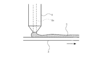
- the coating nozzle 1 having a cylindrical shape and a flat tip surface is used as described above, it is supplied to the surface of the coating object 3 from the nozzle hole 1a at the tip of the coating nozzle 1 as shown in FIG. A part of the coating liquid 2 is guided to the tip of the coating nozzle 1 on the upstream side from the position where the coating liquid 2 is supplied to the coating target 3, and the coating liquid 2 is applied to the coating target 3 by surface tension or the like. 2 is accumulated at the tip of the application nozzle 1 on the upstream side from the position where 2 is supplied, and rises.
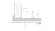
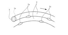
- the coating liquid 2 swelled in this way flows down to the coating object 3, and as shown in FIGS. 2 and 3, a partial swell 2 a of the coating liquid 2 is generated on the coating object 3, as shown in FIG. 4.
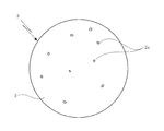
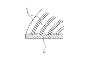
- the coating object 2 to which the coating liquid 2 is applied is present in a state where the partial bulges 2 a of the coating liquid 2 are dispersed, and the coating liquid 2 is uniformly applied to the surface of the coating object 3. There was a problem that became difficult.
- the coating object is held horizontally and rotated, the coating nozzle is guided above the coating object, and the coating nozzle is moved in the radial direction of the rotating coating object while the tip of the coating nozzle is moved. It is an object of the present invention to solve the above-described problems in the case where the coating liquid is ejected from the nozzle holes to apply the coating liquid onto the surface of the object to be coated.
- the coating liquid when the coating liquid is applied to the surface of the coating object rotated as described above, the coating liquid can be uniformly applied to the surface of the coating object from the coating nozzle with a constant thickness. It is an object to do.
- a cylindrical coating nozzle having a flat tip end surface is provided above the coating target object while rotating the coating target object held on the rotary table.
- the coating liquid is discharged from the nozzle hole at the tip of the coating nozzle while the coating nozzle is moved relatively in the direction intersecting the rotation direction of the coating target, and the coating liquid is applied to the surface of the coating target.
- an inclined notch is formed in a part of the tip of the coating nozzle that discharges the coating liquid, and the upstream of the position where the notch in the coating nozzle supplies the coating liquid to the rotating coating object.
- a rotation control means for controlling the rotation of the coating nozzle so as to be located on the side is provided.
- the coating nozzle feed speed vector moved relatively in the direction intersecting the rotation direction of the coating object, and coating Apply the coating nozzle so that the notch of the coating nozzle is located on the same side as the direction of the combined vector with the relative movement speed vector of the coating nozzle relative to the normal direction of the coating object at the position where the coating liquid is supplied from the nozzle. It is preferable to rotate.
- the inclination angle ⁇ of the notch with respect to the flat tip surface of the application nozzle is preferably in the range of 10 ° to 70 °, more preferably the inclination angle of the notch.
- ⁇ is set in the range of 20 ° to 60 °.
- the coating liquid supplied to the surface of the coating object from the nozzle hole at the tip of the coating nozzle is located upstream from the position where the coating liquid is supplied to the coating object by its surface tension or the like.
- the rotation direction of the coating object rotating the coating nozzle is directed toward the outer peripheral side. In addition to being moved relatively outward in the radial direction, it can be moved relatively inward in the radial direction from the outer peripheral side of the rotating application object toward the center of rotation. In addition, from the viewpoint of appropriately controlling the thickness of the coating liquid at the rotation center of the coating object, the thickness is relatively radially outward from the rotation center of the coating object that rotates the coating nozzle toward the outer periphery. It is preferable to move to.
- the coating object held on the rotary table is rotated, and the tip surface is flat above the coating object.
- the coating liquid is discharged from the nozzle hole at the tip of the coating nozzle while the coating nozzle is guided and moved relatively in the direction intersecting the rotation direction of the coating object, and the coating liquid is applied to the coating object.
- a position where an inclined notch is formed at a part of the tip of the coating nozzle for discharging the coating liquid and the coating liquid is supplied to the coating object to be rotated.
- the coating nozzle was rotated so as to be located on the upstream side.
- the electronic device of the present invention is manufactured by applying the coating liquid to the coating object using the above coating apparatus or coating method.
- the coating liquid can be applied evenly and evenly to the surface of the object to be coated.
- FIG. 3 is a partial explanatory view showing a state in which a partial rise of the coating liquid occurs on the coating object when the coating liquid is applied to the coating object by the coating apparatus shown in FIG. 2.
- FIG. 3 is a schematic plan view showing a state in which partial bulges of the coating liquid are dispersed and exist in the coating object when the coating liquid is applied to the coating object by the coating apparatus shown in FIG. 2.
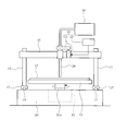
- it is a schematic front view of the coating device which apply
- It is a schematic side view of the coating device in the embodiment.
- the coating liquid is applied to the coating target so that the notch provided at the tip of the coating nozzle is positioned upstream of the position where the coating liquid is supplied to the rotating coating target.
- the notch provided at the tip of the coating nozzle is positioned upstream of the position where the coating liquid is supplied to the rotating coating object, and the nozzle hole at the tip of the coating nozzle is used.
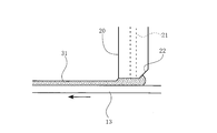
- the coating device in the embodiment it is a partial explanatory view showing an example of the state of the coating liquid supplied from the nozzle hole at the tip of the coating nozzle to the surface of the coating object. It is the partial explanatory view showing the example of change of the coating nozzle used in the coating device in the embodiment.
- the coating object held on the rotary table is rotated as described above, and a cylindrical coating nozzle having a flat tip surface is provided above the coating object.
- the coating liquid is discharged from the nozzle hole at the tip of the coating nozzle while the coating nozzle is moved relatively in the direction intersecting the rotation direction of the coating target, and the coating liquid is applied to the surface of the coating target.
- an inclined notch is formed in a part of the tip of the coating nozzle having a flat tip surface for discharging the coating liquid, and the notch in the coating nozzle is rotated by the rotation control means.
- the coating nozzle was rotated so as to be positioned upstream of the position where the coating liquid was supplied to the coating liquid, that is, on the non-coating side. In this way, the coating liquid discharged from the nozzle hole at the tip of the coating nozzle to the coating target is flat on the surface of the coating target by the flat tip surface of the coating nozzle not provided with the notch. Will be supplied.
- the notch at the tip of the application nozzle is positioned upstream of the position where the application liquid is supplied to the rotating application object.
- the coating liquid is returned to the normal position where the coating liquid is supplied to the surface of the object to be coated by the notch. For this reason, it is prevented that the coating liquid accumulates at the tip of the coating nozzle upstream from the position where the coating liquid is supplied to the coating target due to surface tension or the like and is temporarily supplied to the surface of the coating target.
- the thickness of the coating liquid is constant from the coating nozzle to the surface of the coating object. Can be applied uniformly.
- the coating apparatus and coating method of the present invention when the inclination angle ⁇ of the notch with respect to the flat tip surface of the coating nozzle is in the range of 10 ° to 70 °, particularly in the range of 20 ° to 60 °, the coating is performed. Accumulation of the liquid at the tip of the application nozzle upstream from the position where the application liquid is supplied to the application target is further suppressed, and partial swell occurs in the application liquid applied to the surface of the application target. Thus, the coating liquid can be uniformly applied from the coating nozzle to the surface of the coating object with a more constant thickness.
- the coating apparatus and coating method of the present invention if a chamfered portion smaller than the notched portion is formed along the outer periphery of the tip of the coating nozzle in which the notched portion is formed, it is guided to the notched portion by surface tension or the like.
- the applied liquid is returned to the normal position where the applied liquid is supplied to the application target by the chamfered portion formed along the outer periphery of the application nozzle tip, and the applied liquid stays in the notch. In other words, the coating liquid can be applied more smoothly and uniformly to the surface of the object to be coated.
- a rotary table 12 is attached to the tip of the rotary shaft 11 a of the rotary device 11 extending upward from the base 10. Then, the application target 13 such as a wafer for applying the coating liquid 31 is sucked and held horizontally on the rotary table 12, and in this state, the rotary table 12 attached to the tip of the rotary shaft 11 a by the rotary device 11. I try to rotate it.
- traveling rails 14 are provided on the base 10 on both sides of the rotary table 12, and the platform 15 is caused to travel on the pair of traveling rails 14 by the moving device 17.
- a holding member 16 that rotatably holds the coating nozzle 20 that discharges the coating liquid 31 is attached between the gantry 15 so as to be movable up and down, and the coating nozzle 20 that is held by the holding member 16 is applied to the coating nozzle 20.
- An appropriate amount of coating liquid 31 is supplied from the liquid supply device 30 while being adjusted.
- a nozzle rotating device 41 using a motor or a pulley for rotating the coating nozzle 20 on the holding member 16.
- a control device 42 for controlling the rotation of the coating nozzle 20 by the nozzle rotating device 41.
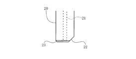
- a cylindrical application nozzle 20 having a flat front end surface for discharging the application liquid 31 from the nozzle hole 21,
- the tip portion is provided with an inclined cutout portion 22.
- the inclination angle ⁇ with respect to the horizontal surface of the notch 22 provided at a part of the tip of the coating nozzle 20 and the ratio of the diameter d of the nozzle hole 21 to the outer diameter D of the coating nozzle 20 (d / D) will be described later.
- the shape of the tip surface of the coating nozzle 20 may be circular, rectangular, or other shape
- the shape of the nozzle hole 21 may be circular, rectangular, or other shape.
- the application object 13 made of the substrate sucked and held on the rotary table 12 is rotated by the rotating device 11 and the application nozzle provided above the application object 13. 20 is moved in the radial direction of the coating object 13 to be rotated by the moving device 17, the coating liquid 31 is discharged from the nozzle hole 21 at the tip of the coating nozzle 20, and the coating liquid 31 is applied to the surface of the coating object 13. The case where it does is demonstrated.
- the moving device 17 causes the gantry 15 to travel along the traveling rail 14, and guides the application nozzle 20 above the rotation center of the application target 13 held on the rotary table 12.
- the holding member 16 attached to the gantry 15 is lowered along the gantry 15, and the tip of the coating nozzle 20 that discharges the coating liquid 31 is placed above the center of rotation of the coating object 13 with a predetermined interval.
- the application object 13 held on the rotary table 12 is rotated by the rotating device 11 and the platform 15 is caused to travel along the traveling rail 14 by the moving device 17 so that the tip of the application nozzle 20 is applied to the application object.
- the object 13 is moved radially outward from the center of rotation toward the outer peripheral side.
- the control device 42 controls the cutout portion 22 provided at the tip of the coating nozzle 20 so as to be located upstream of the position where the coating liquid 31 is supplied to the rotating coating target 13. While controlling the rotation of the application nozzle 20 by the nozzle rotating device 41, the application liquid 31 is discharged from the nozzle hole 21 at the tip of the application nozzle 20 to the application object 13, and the application liquid 31 is applied to the surface of the application object 13. Apply.
- the control device 42 is arranged upstream of the position where the coating liquid 31 is supplied to the coating object 13 on which the notch 22 provided at the tip of the coating nozzle 20 rotates.
- the feed velocity vector Vr in the radial direction of the coating nozzle 20 and the coating liquid 31 are supplied from the coating nozzle 20.
- the direction of the combined vector Vt with the relative movement velocity vector V ⁇ of the application nozzle with respect to the normal direction of the application target 13 at the position is obtained.
- the rotation of the coating nozzle 20 by the nozzle rotating device 41 is controlled so that the notch 22 provided at the tip of the coating nozzle 20 is located on the same side as the direction of the composite vector Vt. .
- the application nozzle 20 itself does not move in the rotation direction of the application target 13, but the application target 13 rotates in the X direction indicated by the arrow in FIG.
- the direction of the object 13 is opposite to the X direction indicated by the arrow.
- the application nozzle 20 is gradually rotated by the nozzle rotation device 41 by the control device 42.
- the notch 22 at the tip of the application nozzle 20 is fed in the radial direction of the application nozzle 20.
- the vector Vr and the relative movement speed vector V ⁇ of the coating nozzle with respect to the normal direction of the coating target 13 at the position of this point A are positioned in the same direction as the direction of the combined vector Vt. Further, when the application nozzle 20 is moved outward in the radial direction to reach the final position where the application is finished, the discharge of the application liquid 31 from the application nozzle 20 is stopped.
- the notch 22 provided at the tip of the coating nozzle 20 is positioned upstream of the position where the coating liquid 31 is supplied to the rotating coating object 13, and the nozzle hole 21 at the tip of the coating nozzle 20.
- the coating liquid 31 is ejected from the surface and the coating liquid 31 is coated on the surface of the coating target 13, the coating discharged to the coating target 13 from the nozzle hole 21 at the tip of the coating nozzle 20, as shown in FIG.
- the liquid 31 is supplied in a flat state to the surface of the application target 13 by the flat front end surface of the application nozzle 20 where the notch 22 is not provided.
- the coating liquid 31 supplied to the coating target 13 is guided to the tip of the coating nozzle 20 on the upstream side from the position where the coating liquid 31 is supplied to the coating target 13, the coating liquid 31 remains upstream.
- the notch 22 located on the side returns to the normal position where the coating liquid 31 is supplied to the surface of the application target 13. For this reason, it is prevented that the coating liquid 31 accumulates at the tip of the coating nozzle 20 on the upstream side due to surface tension or the like and rises.
- the coating liquid 31 swelled on the upstream side of the coating nozzle 20 is temporarily supplied from the tip of the coating nozzle 20 to the surface of the coating object 13 and applied to the surface of the coating object 13.
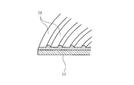
- the coating liquid 31 is uniformly applied to the surface of the coating object 13 with the thickness and width of the coating liquid 31 being constant.
- the swelled coating liquid flows down to the object to be coated, and a partial swell of the coating liquid occurs on the object to be coated with the coating liquid. .
- the inclination angle ⁇ of the notch 22 with respect to the horizontal plane is preferably in the range of 10 ° to 70 °, and more preferably in the range of 20 ° to 60 °. .
- the coating solution 31 to be cut off or faded causes a portion where the coating solution 31 is not applied or a portion where the thickness of the coating solution 31 is reduced.
- the above d / D value becomes too large, as shown in FIG. 11, the portion of the coating liquid 31 previously applied to the coating target 13 and the coating target 13 next. The contact portion with the portion of the coating liquid 31 to be applied is raised.
- a coating nozzle 20 having an outer diameter D of 5 mm and an inclination angle ⁇ with respect to the horizontal plane of the notch 22 is 45 °
- the diameter d of the nozzle hole 21 in the coating nozzle 20 and the viscosity of the coating liquid 31 is used.
- the application liquid 31 was applied to the application object 13 and the above-described experiment was conducted to examine the breakage of the application liquid 31 and the swell of the contact portion of the application liquid 31 as described above.
- the viscosity of the coating liquid 31 is in a generally used range. It was found that the value of / D preferably satisfies the condition of 0.16 ⁇ d ⁇ 0.8, and more preferably satisfies the condition of 0.2 ⁇ d / D ⁇ 0.6.
- the coating nozzle 31 is moved radially outward from the center of rotation of the coating target 13 with respect to the coating target 13 rotating as described above, and the coating liquid 31 is applied to the surface of the coating target 13.
- the rotational speed of the coating object 13 and the feed speed of the coating nozzle 20 in the radial direction can be appropriately controlled in consideration of characteristics such as the viscosity of the coating liquid 31.
- the coating liquid 31 supplied to the coating target 13 from the nozzle hole 21 at the tip of the coating nozzle 20 is brought into close contact with each other in order.
- FIG. 13B a part of the coating liquid 31 supplied to the coating object 13 from the nozzle hole 21 at the tip of the coating nozzle 20 is overlapped.
- the coating liquid 31 can be supplied to the coating object 13.
- the notch 22 of the application nozzle 20 has already been applied. Since the coating liquid 31 is applied to the portion where the coating liquid 31 discharged from the coating nozzle 20 merges, the swell of the coating liquid 31 to the coating nozzle 20 is suppressed even if the amount of the coating liquid 31 increases. can do. Furthermore, by increasing the overlapping portion of the coating liquid 31, variations in the coating thickness of the coating liquid 31 can be suppressed.
- the application nozzle 20 having the inclined cutout portion 22 provided at a part of the tip of the application nozzle 20 is used.
- the cutout portion 22 is formed as shown in FIG.
- the coating nozzle 20 in which a chamfered portion 23 smaller than the cutout portion 22 is formed along the outer periphery of the tip of the coated coating nozzle 20 can also be used.
- the application liquid is applied to the application object 13.
- the coating liquid 31 guided to the notch 22 on the upstream side of the coating nozzle 20 from the position where the coating 31 is supplied is returned to the normal position where the coating liquid 31 is supplied to the coating target 13 by the cornering section 23. It comes to be. As a result, the coating liquid 31 is suppressed from staying in the notch 22, and the coating liquid 31 can be applied to the surface of the application target 13 more smoothly and uniformly.
- the coating nozzle 20 when the coating liquid 31 is applied to the surface of the coating object 13, the coating nozzle 20 is moved from the center of rotation of the coating object 13 to the outer peripheral side with respect to the rotating coating object 13. However, it is also possible to move the coating nozzle 20 radially inward from the outer peripheral side of the coating object 13 to be rotated toward the center of rotation. It is.
- the application nozzle 20 is moved radially inward from the outer peripheral side of the application object 13 to be rotated toward the center of rotation in this way, it is provided at the tip of the application nozzle 20 as described above.
- the notch 22 is positioned upstream of the position where the coating liquid 31 is supplied to the rotating coating object 13, and the coating liquid 31 is discharged from the nozzle hole 21 at the tip of the coating nozzle 20.
- the coating liquid 31 is applied to the surface of the object 13, the coating liquid 31 is prevented from rising to the upstream side of the coating nozzle 20 due to surface tension or the like, as in the above case.
- the coating liquid 31 is uniformly applied to the surface of the coating object 13 in a state where the thickness and width of the coating liquid 31 are constant.
- the application of the application liquid 31 when the application of the application liquid 31 is started, the application is started from a position where the nozzle hole 21 of the application nozzle 20 is shifted in the direction opposite to the moving direction of the application nozzle 20 from the rotation center of the application object 13. Then, the delay until the coating liquid 31 is discharged from the nozzle hole 21 can be corrected.
- the application liquid 31 is apparently applied spirally to the surface of the application object 13 when the moving speed is a certain rate.
- a ceramic substrate, a silicon substrate, a glass substrate, a plastic substrate, a metal plate, or the like can be used as the application target 13.
- the application target 13 to which the coating liquid 31 is applied as described above can be effectively used for medical devices such as electronic devices and biochips.
Landscapes
- Physics & Mathematics (AREA)
- Nonlinear Science (AREA)
- Chemical & Material Sciences (AREA)
- Crystallography & Structural Chemistry (AREA)
- General Physics & Mathematics (AREA)
- Optics & Photonics (AREA)
- Coating Apparatus (AREA)
- Application Of Or Painting With Fluid Materials (AREA)
Abstract
Priority Applications (3)
| Application Number | Priority Date | Filing Date | Title |
|---|---|---|---|
| JP2011518422A JP5560273B2 (ja) | 2009-06-08 | 2010-05-28 | 塗布装置、塗布方法及び電子デバイス |
| CN201080016725.XA CN102387869B (zh) | 2009-06-08 | 2010-05-28 | 涂布装置、涂布方法及电子器件 |
| US13/268,230 US8919277B2 (en) | 2009-06-08 | 2011-10-07 | Coating applicator, coating application method and electronic device |
Applications Claiming Priority (2)
| Application Number | Priority Date | Filing Date | Title |
|---|---|---|---|
| JP2009-137231 | 2009-06-08 | ||
| JP2009137231 | 2009-06-08 |
Related Child Applications (1)
| Application Number | Title | Priority Date | Filing Date |
|---|---|---|---|
| US13/268,230 Continuation US8919277B2 (en) | 2009-06-08 | 2011-10-07 | Coating applicator, coating application method and electronic device |
Publications (1)
| Publication Number | Publication Date |
|---|---|
| WO2010143541A1 true WO2010143541A1 (fr) | 2010-12-16 |
Family
ID=43308796
Family Applications (1)
| Application Number | Title | Priority Date | Filing Date |
|---|---|---|---|
| PCT/JP2010/059059 Ceased WO2010143541A1 (fr) | 2009-06-08 | 2010-05-28 | Dispositif d'application, procédé d'application et dispositif électronique |
Country Status (6)
| Country | Link |
|---|---|
| US (1) | US8919277B2 (fr) |
| JP (1) | JP5560273B2 (fr) |
| KR (1) | KR101541211B1 (fr) |
| CN (1) | CN102387869B (fr) |
| TW (1) | TWI524947B (fr) |
| WO (1) | WO2010143541A1 (fr) |
Families Citing this family (7)
| Publication number | Priority date | Publication date | Assignee | Title |
|---|---|---|---|---|
| CN102698930A (zh) * | 2012-06-25 | 2012-10-03 | 张家港市光学仪器有限公司 | 一种点胶机 |
| JP6177055B2 (ja) * | 2012-10-29 | 2017-08-09 | キヤノン株式会社 | 塗工装置、塗工方法、定着部材の製造装置、定着部材の製造方法 |
| CN104668168B (zh) * | 2015-03-12 | 2017-04-05 | 金华职业技术学院 | 一种圆柱形套类零件外表面螺旋色条的喷涂方法 |
| JP7112917B2 (ja) * | 2018-09-12 | 2022-08-04 | タツモ株式会社 | 塗布装置及び塗布方法 |
| WO2020112816A1 (fr) * | 2018-11-29 | 2020-06-04 | Surmodics, Inc. | Appareil et méthodes de revêtement de dispositifs médicaux |
| US11819590B2 (en) | 2019-05-13 | 2023-11-21 | Surmodics, Inc. | Apparatus and methods for coating medical devices |
| CN113814118A (zh) * | 2021-09-22 | 2021-12-21 | 湖南芷江正向科技有限公司 | 一种自动化电子元器件高效涂胶设备 |
Citations (2)
| Publication number | Priority date | Publication date | Assignee | Title |
|---|---|---|---|---|
| JP2005111295A (ja) * | 2003-10-02 | 2005-04-28 | Tokyo Electron Ltd | 塗布膜形成方法及び塗布膜形成装置 |
| JP2006130429A (ja) * | 2004-11-08 | 2006-05-25 | Nitto Denko Corp | クリーニング機能付き搬送部材の製造方法 |
Family Cites Families (9)
| Publication number | Priority date | Publication date | Assignee | Title |
|---|---|---|---|---|
| US6261367B1 (en) * | 1999-05-10 | 2001-07-17 | Nordson Corporation | Method and apparatus for dispensing liquid material |
| JP4145468B2 (ja) | 1999-07-29 | 2008-09-03 | 中外炉工業株式会社 | 円形塗布膜および環状塗布膜の形成方法 |
| JP3776745B2 (ja) | 2001-04-25 | 2006-05-17 | 東京エレクトロン株式会社 | 塗布膜形成方法及びその装置 |
| JP4041301B2 (ja) | 2001-10-18 | 2008-01-30 | シーケーディ株式会社 | 液膜形成方法 |
| JP2003211045A (ja) * | 2002-01-24 | 2003-07-29 | Three Bond Co Ltd | 材料塗布装置 |
| US6869234B2 (en) * | 2002-03-28 | 2005-03-22 | Dainippon Screen Mfg. Co., Ltd. | Developing apparatus and developing method |
| CN1976761B (zh) * | 2005-04-28 | 2011-04-13 | 芝浦机械电子株式会社 | 溶液的涂敷装置及涂敷方法 |
| JP4673180B2 (ja) * | 2005-10-13 | 2011-04-20 | 東京エレクトロン株式会社 | 塗布装置及び塗布方法 |
| JP5171056B2 (ja) * | 2007-02-14 | 2013-03-27 | 本田技研工業株式会社 | 接着剤塗布装置 |
-
2010
- 2010-05-28 CN CN201080016725.XA patent/CN102387869B/zh active Active
- 2010-05-28 JP JP2011518422A patent/JP5560273B2/ja not_active Expired - Fee Related
- 2010-05-28 KR KR1020117021939A patent/KR101541211B1/ko active Active
- 2010-05-28 WO PCT/JP2010/059059 patent/WO2010143541A1/fr not_active Ceased
- 2010-06-02 TW TW099117725A patent/TWI524947B/zh not_active IP Right Cessation
-
2011
- 2011-10-07 US US13/268,230 patent/US8919277B2/en active Active
Patent Citations (2)
| Publication number | Priority date | Publication date | Assignee | Title |
|---|---|---|---|---|
| JP2005111295A (ja) * | 2003-10-02 | 2005-04-28 | Tokyo Electron Ltd | 塗布膜形成方法及び塗布膜形成装置 |
| JP2006130429A (ja) * | 2004-11-08 | 2006-05-25 | Nitto Denko Corp | クリーニング機能付き搬送部材の製造方法 |
Also Published As
| Publication number | Publication date |
|---|---|
| US8919277B2 (en) | 2014-12-30 |
| KR101541211B1 (ko) | 2015-07-31 |
| JPWO2010143541A1 (ja) | 2012-11-22 |
| KR20120026025A (ko) | 2012-03-16 |
| TWI524947B (zh) | 2016-03-11 |
| JP5560273B2 (ja) | 2014-07-23 |
| US20120025145A1 (en) | 2012-02-02 |
| CN102387869B (zh) | 2015-07-08 |
| CN102387869A (zh) | 2012-03-21 |
| TW201100178A (en) | 2011-01-01 |
Similar Documents
| Publication | Publication Date | Title |
|---|---|---|
| JP5560273B2 (ja) | 塗布装置、塗布方法及び電子デバイス | |
| JP4760516B2 (ja) | 塗布装置及び塗布方法 | |
| CN1255220C (zh) | 改善基底上湿涂层均匀性以及涂布移动卷材的方法及设备 | |
| US10279368B2 (en) | Coating method and coating apparatus | |
| CN103008175B (zh) | 涂覆设备和涂覆方法 | |
| TWI524400B (zh) | 基板處理裝置及基板處理方法 | |
| US20150151311A1 (en) | Spin coating apparatus and spin coating method | |
| WO2016152308A1 (fr) | Procédé de revêtement | |
| US6974600B2 (en) | Method and apparatus for coating a photosensitive material | |
| JP5327238B2 (ja) | 塗布処理装置、塗布処理方法及び記憶媒体 | |
| CN1235267C (zh) | 处理溶液施用方法 | |
| WO2018008325A1 (fr) | Procédé de revêtement | |
| JP7261055B2 (ja) | 回転塗布装置及び回転塗布方法 | |
| JP5933724B2 (ja) | 支持ウェハを被覆する装置及び方法 | |
| TWI905353B (zh) | 塗佈處理裝置、塗佈處理方法及電腦記憶媒體 | |
| WO2019146241A1 (fr) | Procédé d'application | |
| JP6947538B2 (ja) | 塗布装置 | |
| JP2001179157A (ja) | 液体の塗布ノズル及び塗布装置及び塗布方法 | |
| JP2004153262A (ja) | スピンコート法 | |
| JP2017195248A (ja) | 塗布方法 | |
| JP2015033654A (ja) | 塗布装置 |
Legal Events
| Date | Code | Title | Description |
|---|---|---|---|
| WWE | Wipo information: entry into national phase |
Ref document number: 201080016725.X Country of ref document: CN |
|
| 121 | Ep: the epo has been informed by wipo that ep was designated in this application |
Ref document number: 10786072 Country of ref document: EP Kind code of ref document: A1 |
|
| WWE | Wipo information: entry into national phase |
Ref document number: 2011518422 Country of ref document: JP |
|
| ENP | Entry into the national phase |
Ref document number: 20117021939 Country of ref document: KR Kind code of ref document: A |
|
| NENP | Non-entry into the national phase |
Ref country code: DE |
|
| 122 | Ep: pct application non-entry in european phase |
Ref document number: 10786072 Country of ref document: EP Kind code of ref document: A1 |