WO2010143552A1 - Dispositif d'affichage à cristaux liquides du type à transmission - Google Patents
Dispositif d'affichage à cristaux liquides du type à transmission Download PDFInfo
- Publication number
- WO2010143552A1 WO2010143552A1 PCT/JP2010/059216 JP2010059216W WO2010143552A1 WO 2010143552 A1 WO2010143552 A1 WO 2010143552A1 JP 2010059216 W JP2010059216 W JP 2010059216W WO 2010143552 A1 WO2010143552 A1 WO 2010143552A1
- Authority
- WO
- WIPO (PCT)
- Prior art keywords
- light
- liquid crystal
- diffusion layer
- backlight
- light diffusion
- Prior art date
- Legal status (The legal status is an assumption and is not a legal conclusion. Google has not performed a legal analysis and makes no representation as to the accuracy of the status listed.)
- Ceased
Links
Images






Classifications
-
- G—PHYSICS
- G02—OPTICS
- G02B—OPTICAL ELEMENTS, SYSTEMS OR APPARATUS
- G02B5/00—Optical elements other than lenses
- G02B5/02—Diffusing elements; Afocal elements
-
- G—PHYSICS
- G02—OPTICS
- G02B—OPTICAL ELEMENTS, SYSTEMS OR APPARATUS
- G02B6/00—Light guides; Structural details of arrangements comprising light guides and other optical elements, e.g. couplings
- G02B6/0001—Light guides; Structural details of arrangements comprising light guides and other optical elements, e.g. couplings specially adapted for lighting devices or systems
- G02B6/0011—Light guides; Structural details of arrangements comprising light guides and other optical elements, e.g. couplings specially adapted for lighting devices or systems the light guides being planar or of plate-like form
- G02B6/0033—Means for improving the coupling-out of light from the light guide
- G02B6/005—Means for improving the coupling-out of light from the light guide provided by one optical element, or plurality thereof, placed on the light output side of the light guide
- G02B6/0051—Diffusing sheet or layer
-
- G—PHYSICS
- G02—OPTICS
- G02F—OPTICAL DEVICES OR ARRANGEMENTS FOR THE CONTROL OF LIGHT BY MODIFICATION OF THE OPTICAL PROPERTIES OF THE MEDIA OF THE ELEMENTS INVOLVED THEREIN; NON-LINEAR OPTICS; FREQUENCY-CHANGING OF LIGHT; OPTICAL LOGIC ELEMENTS; OPTICAL ANALOGUE/DIGITAL CONVERTERS
- G02F1/00—Devices or arrangements for the control of the intensity, colour, phase, polarisation or direction of light arriving from an independent light source, e.g. switching, gating or modulating; Non-linear optics
- G02F1/01—Devices or arrangements for the control of the intensity, colour, phase, polarisation or direction of light arriving from an independent light source, e.g. switching, gating or modulating; Non-linear optics for the control of the intensity, phase, polarisation or colour
- G02F1/13—Devices or arrangements for the control of the intensity, colour, phase, polarisation or direction of light arriving from an independent light source, e.g. switching, gating or modulating; Non-linear optics for the control of the intensity, phase, polarisation or colour based on liquid crystals, e.g. single liquid crystal display cells
- G02F1/133—Constructional arrangements; Operation of liquid crystal cells; Circuit arrangements
- G02F1/1333—Constructional arrangements; Manufacturing methods
- G02F1/1335—Structural association of cells with optical devices, e.g. polarisers or reflectors
-
- G—PHYSICS
- G02—OPTICS
- G02F—OPTICAL DEVICES OR ARRANGEMENTS FOR THE CONTROL OF LIGHT BY MODIFICATION OF THE OPTICAL PROPERTIES OF THE MEDIA OF THE ELEMENTS INVOLVED THEREIN; NON-LINEAR OPTICS; FREQUENCY-CHANGING OF LIGHT; OPTICAL LOGIC ELEMENTS; OPTICAL ANALOGUE/DIGITAL CONVERTERS
- G02F1/00—Devices or arrangements for the control of the intensity, colour, phase, polarisation or direction of light arriving from an independent light source, e.g. switching, gating or modulating; Non-linear optics
- G02F1/01—Devices or arrangements for the control of the intensity, colour, phase, polarisation or direction of light arriving from an independent light source, e.g. switching, gating or modulating; Non-linear optics for the control of the intensity, phase, polarisation or colour
- G02F1/13—Devices or arrangements for the control of the intensity, colour, phase, polarisation or direction of light arriving from an independent light source, e.g. switching, gating or modulating; Non-linear optics for the control of the intensity, phase, polarisation or colour based on liquid crystals, e.g. single liquid crystal display cells
- G02F1/133—Constructional arrangements; Operation of liquid crystal cells; Circuit arrangements
- G02F1/1333—Constructional arrangements; Manufacturing methods
- G02F1/1335—Structural association of cells with optical devices, e.g. polarisers or reflectors
- G02F1/133504—Diffusing, scattering, diffracting elements
-
- G—PHYSICS
- G02—OPTICS
- G02F—OPTICAL DEVICES OR ARRANGEMENTS FOR THE CONTROL OF LIGHT BY MODIFICATION OF THE OPTICAL PROPERTIES OF THE MEDIA OF THE ELEMENTS INVOLVED THEREIN; NON-LINEAR OPTICS; FREQUENCY-CHANGING OF LIGHT; OPTICAL LOGIC ELEMENTS; OPTICAL ANALOGUE/DIGITAL CONVERTERS
- G02F1/00—Devices or arrangements for the control of the intensity, colour, phase, polarisation or direction of light arriving from an independent light source, e.g. switching, gating or modulating; Non-linear optics
- G02F1/01—Devices or arrangements for the control of the intensity, colour, phase, polarisation or direction of light arriving from an independent light source, e.g. switching, gating or modulating; Non-linear optics for the control of the intensity, phase, polarisation or colour
- G02F1/13—Devices or arrangements for the control of the intensity, colour, phase, polarisation or direction of light arriving from an independent light source, e.g. switching, gating or modulating; Non-linear optics for the control of the intensity, phase, polarisation or colour based on liquid crystals, e.g. single liquid crystal display cells
- G02F1/133—Constructional arrangements; Operation of liquid crystal cells; Circuit arrangements
- G02F1/1333—Constructional arrangements; Manufacturing methods
- G02F1/1335—Structural association of cells with optical devices, e.g. polarisers or reflectors
- G02F1/1336—Illuminating devices
- G02F1/133602—Direct backlight
- G02F1/133606—Direct backlight including a specially adapted diffusing, scattering or light controlling members
- G02F1/133607—Direct backlight including a specially adapted diffusing, scattering or light controlling members the light controlling member including light directing or refracting elements, e.g. prisms or lenses
-
- G—PHYSICS
- G02—OPTICS
- G02F—OPTICAL DEVICES OR ARRANGEMENTS FOR THE CONTROL OF LIGHT BY MODIFICATION OF THE OPTICAL PROPERTIES OF THE MEDIA OF THE ELEMENTS INVOLVED THEREIN; NON-LINEAR OPTICS; FREQUENCY-CHANGING OF LIGHT; OPTICAL LOGIC ELEMENTS; OPTICAL ANALOGUE/DIGITAL CONVERTERS
- G02F1/00—Devices or arrangements for the control of the intensity, colour, phase, polarisation or direction of light arriving from an independent light source, e.g. switching, gating or modulating; Non-linear optics
- G02F1/01—Devices or arrangements for the control of the intensity, colour, phase, polarisation or direction of light arriving from an independent light source, e.g. switching, gating or modulating; Non-linear optics for the control of the intensity, phase, polarisation or colour
- G02F1/13—Devices or arrangements for the control of the intensity, colour, phase, polarisation or direction of light arriving from an independent light source, e.g. switching, gating or modulating; Non-linear optics for the control of the intensity, phase, polarisation or colour based on liquid crystals, e.g. single liquid crystal display cells
- G02F1/133—Constructional arrangements; Operation of liquid crystal cells; Circuit arrangements
- G02F1/1333—Constructional arrangements; Manufacturing methods
- G02F1/1335—Structural association of cells with optical devices, e.g. polarisers or reflectors
- G02F1/1336—Illuminating devices
- G02F1/133615—Edge-illuminating devices, i.e. illuminating from the side
Definitions
- the present invention relates to a transmissive liquid crystal display device.
- the transmissive liquid crystal display device is widely used as a typical flat panel display because of its excellent features such as thinness, light weight and low power consumption. In particular, it has been widely used as a TV, personal computer monitor, in-vehicle display, and mobile phone. Since the liquid crystal itself is a non-light-emitting device, it can be roughly classified into three types, a transmission type, a transflective type, and a reflective type, depending on the light irradiation method from the light source. Under circumstances where the external light is relatively weak, high image quality is realized by a transmission type system that can stably emit light of appropriate intensity from the backlight. Therefore, transmissive liquid crystal display devices are mainly used in applications that require high image quality, such as televisions and personal computer monitors.
- the liquid crystal has a TN mode, a VA mode, an IPS mode, an OCB mode and the like in relation to the molecular arrangement. These have a viewing angle dependency due to the respective optical characteristics. Accordingly, even when the image quality such as contrast and color is designed to be good in the normal direction (front direction) of the liquid crystal panel, the image quality is deteriorated in the oblique direction.
- a method using a viewing angle compensation film as shown in FIG. 10 and a method using a light diffusion layer as shown in FIG. 11 have been proposed.
- the backlight having a wide angle emitted from the backlight light source 1 is transmitted through the diffuser plate 2 and then includes the viewing angle compensation film 3. Passes through the liquid crystal panel 4.
- the viewing angle compensation film 3 is used to compensate for the phase difference between the light passing through the liquid crystal layer in the normal direction and the light passing through the liquid crystal layer.
- FIG. 10 shows the case where two viewing angle compensation films are used, there are cases where only one or three or more are used.
- the transparent protective film also serves as a viewing angle compensation film.
- this viewing angle compensation film requires a high degree of birefringence control, it is generally more expensive than other optical films.
- the phase difference between the light passing through the liquid crystal layer in the normal direction and the light passing obliquely depends on the wavelength. Therefore, the viewing angle compensation film needs to be adjusted to have birefringence wavelength dispersibility suitable for the liquid crystal layer to be used. Those having characteristics are not easily obtained.
- the light emitted from the backlight source 1 and passing through the light guide plate 6 passes through the liquid crystal panel 4 and the light diffusing layer 5 in this order. Pass along the normal direction.
- a light diffusion layer for example, a light diffusion layer is proposed in which transparent fine particles are spread between a polarizing plate and a glass substrate, and the gaps between the fine particles are filled with a transparent filler (see, for example, Patent Document 1). .
- a method has been proposed in which a light diffusion film in which scatterers are dispersed in a transparent resin is used as a protective film for a polarizing plate (for example, see Patent Document 2).
- a flat thing is described as a scatterer disperse
- the method using the light diffusing layer is hardly used because of a problem of a decrease in contrast due to external light.
- Patent Document 3 A method of using a viewing angle compensation film and a light diffusion layer in combination has also been proposed (see, for example, Patent Document 3).
- a viewing angle compensation sheet mainly composed of a liquid crystalline compound and a light diffusing layer are used in combination to improve the OCB mode viewing angle, a cellulose acetate film having optical anisotropy, and a light diffusing layer. Is used together to improve the viewing angle of the VA mode.
- the above-mentioned problem in the light diffusion layer has not been solved yet.
- the present invention has been made in view of the above-described conventional circumstances, and an object of the present invention is to provide a transmissive liquid crystal display device that suppresses a decrease in contrast due to external light while realizing a wide viewing angle.
- the invention according to claim 1 at least, A backlight light source;
- Light control means for controlling the directivity of light emitted from the backlight light source;
- a transmissive liquid crystal cell In order from the side closer to the light control means, a transmissive liquid crystal cell, a light diffusing layer containing a translucent polymer, a scatterer, and a colorant,
- a transmissive liquid crystal display device having
- the invention according to claim 2 2.
- the invention according to claim 3 The transmissive liquid crystal display device according to claim 1, wherein the light diffusion layer has an internal absorbance of 0.020 or more at a main wavelength of light emitted from the backlight light source.
- the invention according to claim 4 The transmissive liquid crystal according to any one of claims 1 to 3, wherein the light diffusion layer has an internal absorbance of 0.028 or more and 0.062 or less at a main wavelength of light emitted from the backlight light source. It is a display device.
- the invention according to claim 5 5.
- the invention according to claim 6 The light diffusion layer is a laminate of a scattering layer in which the light scatterers are dispersed in the light-transmitting polymer and a colored layer containing the light-transmitting polymer and the colorant.
- the present invention it is possible to provide a transmissive liquid crystal display device that realizes a wide viewing angle and suppresses a decrease in contrast due to external light.
- 1 is a schematic cross-sectional view illustrating an exemplary configuration of a transmissive liquid crystal display device of the present invention. 2 is an internal absorbance spectrum of Samples 11 to 14 in Example 1. 3 is an internal transmittance spectrum of Samples 11 to 14 in Example 1.
- the transmissive liquid crystal display device of the present invention comprises at least a backlight light source, a light control means for controlling the directivity of light emitted from the backlight light source, and a transmissive type in order from the side closer to the light control means.
- a liquid crystal cell ; and a light diffusion layer containing a light-transmitting polymer, a scatterer, and a colorant.
- a viewing angle compensation film as shown in FIG. 10 is used in order to reduce a color shift due to a viewing angle of a liquid crystal display.
- the viewing angle compensation film must be provided with appropriate birefringence wavelength dispersion.
- birefringence wavelength dispersion is a characteristic inherent to the material, and it is not easy to obtain a polymer having ideal wavelength dispersion.
- a method using the light diffusion layer shown in FIG. 11, that is, a method using both a backlight having a relatively high directivity and the light diffusion layer is employed.
- problems with the method using the viewing angle compensation film such as reduction of the color shift of the viewing angle caused by the passage of light at a large angle with respect to the normal direction (0 °) of the liquid crystal panel
- a wide viewing angle can be realized.
- the light diffusion layer according to the present invention contains a scatterer, it diffuses a relatively directional backlight and realizes a wide viewing angle. Further, since the light diffusion layer according to the present invention contains a colorant such as a pigment, it has a function of absorbing incident external light, and the light diffusion layer is located on the side farther from the backlight than the liquid crystal cell. Specifically, for example, as a (transparent) protective layer provided on the observer side or on the outside of the transparent protective layer, a decrease in contrast is suppressed.
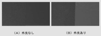
- FIG. 12 was taken of a liquid crystal display (right half side) with a PMMA polymer film (light diffusion layer) added with alumina fine particles added on the forefront and a liquid crystal display without the film (left half side). It is a photograph.
- FIG. 12 (A) is taken in a state where the room is darkened and no external light hits the liquid crystal display
- FIG. 12 (B) is a fluorescent lamp on the ceiling of the room, I'm shooting with the light hitting the LCD.
- FIGS. 12A and 12B when a light diffusing layer is arranged on a liquid crystal display and exposed to external light, whitening occurs and contrast decreases (right side of FIG. 12B). .
- the reason for whitening and lowering the contrast in FIG. 12B in which external light is applied is that the external light enters the light diffusion layer and scatters again. This is because the light returns to the outside (observer side) of the light diffusion layer.
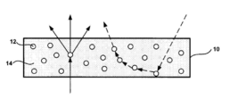
- FIG. 1 shows a first embodiment of such a light diffusion layer.
- the scatterers 12 are dispersed in the translucent polymer 14, and more desirably, the scatterers 12 are uniformly distributed in the translucent polymer 14.
- the translucent polymer 14 contains a colorant (not shown) such as a pigment.
- the reason why return light due to external light that causes whitening can be attenuated by including a colorant in the light diffusion layer 10 is estimated as follows.
- the present invention is not limited by such estimation.
- the light reaching the observer's eyes out of the light from the backlight is light that has been scattered about once to several times and passed through the light diffusion layer 10.
- the external light that reaches the eyes of the observer is light that has entered the light diffusion layer 10 and then repeatedly scattered more times by the scatterer 12 and returned to the observer side. Therefore, external light travels a longer distance in the light diffusion layer 10 than the light from the backlight (see the broken line arrow in FIG. 2).
- the light diffusing layer 10 contains a colorant
- external light traveling over a long distance is gradually absorbed by the colorant, and return light due to external light that causes whitening can be attenuated.
- the configuration of the light diffusion layer is not limited to that shown in FIG. FIG. 3 shows a second embodiment of the light diffusion layer.
- the scatterers 12 are distributed in the light diffusion layer 10 so as to be biased toward the liquid crystal layer in the thickness direction.
- the scatterers 12 may be arranged at an appropriate interval, may be in contact with each other, or may be irregularly arranged.
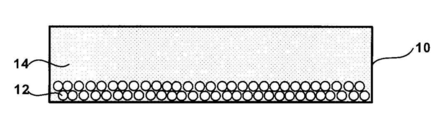
- FIG. 4 shows a third embodiment of the light diffusion layer.
- the scatterers 12 are arranged in a plurality of layers in the thickness direction of the light diffusion layer.
- the scatterer 12 does not necessarily have to form a regular layer.
- FIG. 5 shows a fourth embodiment of the light diffusion layer.
- a colored layer 18 including a light-transmitting polymer 14 and a colorant is provided on the outer side (observer side) of the scattering layer 16 including the light-transmitting polymer 14 and the scatterer 12.
- the scattering layer 16 does not need to contain a colorant, but may contain it.
- the external light observed as the return light can be obtained by using the light diffusing layer having the configuration of FIGS. Since the light travels a longer distance in the light diffusion layer, external light can be attenuated preferentially.
- the light diffusion layer having the configuration shown in FIG. 5 can effectively attenuate external light.
- the scattering layer 16 shown in FIG. 5 may have a distribution in which the scatterers 12 are biased in the film thickness direction as shown in FIGS. 3 and 4.
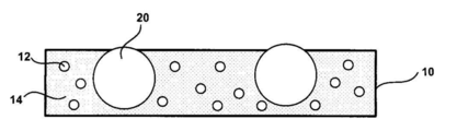
- the outside of the light diffusion layer 10 may be subjected to antireflection or antiglare treatment using a known technique. It is also possible to introduce anti-glare particles 20 into the light diffusion layer 10 as shown in FIG.
- organic dyes are suitable as the colorant, but organic pigments and inorganic pigments can also be used as long as they are miniaturized to such an extent that the resolution of the image is not significantly deteriorated and the dispersion state is good.
- organic pigments and inorganic pigments such as carbon black, anthraquinone compounds, perylene compounds, disazo compounds, phthalocyanine compounds, isoindoline compounds, and dioxazine compounds can be used.
- the kind of organic dye is not particularly limited.
- the colorant may be used alone or in combination of a plurality of types.
- the internal absorbance spectrum obtained by combining one or a plurality of light absorbers should ideally have substantially the same value over the entire wavelength range of visible light (about 380 nm to about 750 nm).
- a cold cathode tube or an LED is often used, and usually has light intensity peaks at three main wavelengths corresponding to red (R), green (G), and blue (B). . Therefore, the light absorption of the dye added in the present invention does not necessarily have the same absorbance (transmittance) in the entire visible light wavelength region as described above, and is obtained by adjusting an appropriate absorbance balance in the three main wavelengths of the backlight. It may be.
- the difference in internal absorbance of the light diffusion layer at the main wavelength of the light emitted from the backlight light source is as small as possible.
- the difference is adjusted so that the difference between the internal absorbances of the light diffusion layers at wavelengths of about 435 nm, about 545 nm, and about 615 nm is as small as possible.
- the difference between the internal absorbances of the light diffusion layers at the main wavelength of the light emitted from the backlight light source is preferably 0.05 or less, more preferably 0.02 or less, and 0 More preferably, it is .01 or less.
- the main wavelengths of light emitted from the backlight light source are, for example, three wavelengths of about 435 nm, about 545 nm, and about 615 nm in a general cold cathode tube.
- a light source having a main wavelength other than three wavelengths may be used as a backlight.
- the four wavelengths are set as the main wavelengths.
- an LED it may have a main wavelength different from that of the general cold cathode tube.
- the main wavelength of the light emitted from the backlight light source does not greatly deviate even after passing through the light control means for controlling the directivity, but the main wavelength of the light after passing through the light control means
- the internal absorbance of the light diffusion layer may be adjusted according to the above.
- the color filter provided in the liquid crystal cell and the resin in each layer may attenuate light of a specific wavelength or shift the peak wavelength.
- the internal absorbance of the light diffusion layer may be adjusted according to the main wavelength of the light immediately before entering the light diffusion layer, taking into account the spectrum of the light immediately before entering the light diffusion layer.
- Table 1 shows the internal absorbance and transmittance of an example of the light scattering layer of the present invention, in which the internal absorbance is adjusted according to the main wavelength of a general cold cathode tube.
- the internal absorbance of the light diffusion layer at the main wavelength of the light emitted from the backlight light source is adjusted to 0.014 or more. It is suitable, it is more preferable that it is 0.020 or more, and it is more preferable that it is 0.028 or more. Further, considering the front luminance, it is preferable to adjust the internal absorbance of the light diffusion layer at the main wavelength of the light emitted from the backlight light source to a range of 0.014 to 0.095.
- it is in the range of 014 to 0.088, more preferably in the range of 0.020 to 0.088, still more preferably in the range of 0.028 to 0.088. More preferably, it is in the range of not less than 0.028 and not more than 0.062.
- the light-transmitting polymer 14 and the scatterer 12 in the light diffusion layer are appropriately selected so that the combination of the respective refractive indexes and the size of the scatterer 12 have appropriate values.
- the translucent polymer 14 used for the light diffusion layer a cellulose derivative typified by triacetyl cellulose, an acrylic polymer typified by polymethyl methacrylate, a cycloolefin polymer typified by polycarbonate, a norbornene-based polymer, etc.
- Various translucent polymers can be used, but are not limited thereto.
- the light-transmitting polymer 14 used in the light diffusion layer may be a homopolymer or a copolymer, or may be a blend of polymers. Further, these polymers may be high-purity polymers that hardly contain other additives, or may contain various additives such as plasticizers. Further, the translucent polymer 14 may be a polymer having adhesiveness.
- the refractive index of the translucent polymer 14 is appropriately selected depending on the combination with the scatterer 12 and the like to be added, and thus is not generally specified, but is generally preferably 1.33 to 1.65. More preferably, it is 45 to 1.60.
- the refractive index of triacetyl cellulose is 1.48
- the refractive index of polymethyl methacrylate is 1.49.
- translucent particles are suitable. Specifically, alumina particles, silicone polymer particles, melamine / formaldehyde condensate particles, benzoguanamine / formaldehyde condensate particles, benzoguanamine / melamine / formaldehyde condensate particles, titanium oxide particles, silica particles, etc. can be used. It is not limited to.
- the average particle diameter of the scatterer 12 is appropriately selected depending on the combination with the above-described translucent polymer 14 and the like, and thus is not specified unconditionally. However, in general, it is preferably 0.05 ⁇ m or more and 25 ⁇ m or less. It is more preferably 1 ⁇ m or more and 20 ⁇ m or less, and further preferably 0.8 ⁇ m or more and 18 ⁇ m or less.
- the refractive index of the scatterer is also not generally specified because it is appropriately selected depending on the combination with the above-described light-transmitting polymer, etc., but is generally 1.40 to 2.75, preferably 1.43 More preferably, it is ⁇ 1.9. Further, the refractive index of the scatterer 12 is preferably 0.02 to 1.25, more preferably 0.03 to 0.30, with respect to the refractive index of the translucent polymer 14. The refractive index difference in the above range is preferable from the viewpoint of the effect of light diffusion.
- the content of the scatterer 12 with respect to the translucent polymer 14 is not generally specified because it is appropriately adjusted depending on the type of the translucent polymer 14 and the type and size of the scatterer 12.
- the content is preferably from 50% by mass to 50% by mass, and more preferably from 0.5% by mass to 15% by mass.
- the light diffusion layer according to the present invention has a function of diffusing light and a function of absorbing light.
- the luminance of the backlight before entering the liquid crystal panel (corresponding to before entering the transparent protective layer 26 in FIG. 7) It can be evaluated by comparing the angular distribution and the angular distribution of luminance after the light from the backlight passes through the liquid crystal panel and is diffused by the light diffusion layer. More simply, it can be evaluated by measuring the haze (Haze) of a film sample obtained by adding a scatterer to a translucent polymer.
- the haze is 70%.
- the internal absorbance of the light diffusion layer at the main wavelength of light emitted from the backlight light source is 0.028 or more. It is preferable to adjust to 0.028 or more and 0.088 or less, more preferably 0.028 or more and 0.062 or less, and 0.055 or more and 0.062 or less. The following range is desirable from the viewpoint of maintaining high front luminance while displaying good black.
- a backlight having lower directivity even a haze having a lower haze can be sufficiently diffused.
- the haze is desirably 60% or more, and more desirably 70% or more.
- the inside of the light diffusion layer at the main wavelength of light emitted from the backlight light source is used.
- the absorbance is preferably adjusted to 0.020 or more, more preferably 0.020 or more and 0.095 or less, and further preferably 0.020 or more and 0.068 or less.
- the range of 0.029 or more and 0.068 or less is desirable from the viewpoint of maintaining high front luminance while displaying good black.
- the preferred haze value and the range of the internal absorbance are slightly different depending on the directivity of light from the backlight used, any directivity light can be used from the viewpoint of suppressing whitening of the screen.
- any directivity light can be used from the viewpoint of suppressing whitening of the screen.
- the effect can be obtained by adjusting the internal absorbance of the light diffusion layer to 0.014 or more.
- the function of absorbing light can be evaluated by measuring the absorbance (or transmittance) with a commercially available measuring instrument.
- a film sample in which a light absorbing agent is added to a translucent polymer is used.
- the absorbance inside the film thus obtained is defined as internal absorbance.
- the attenuation rate and transmittance are determined from the internal absorbance. These are defined as internal attenuation rate (%) and internal transmittance (%), respectively. The sum of the internal attenuation and the internal transmittance is 100%.
- a light diffusion layer suitably designed based on the above evaluation results is installed in a transmissive liquid crystal display device having a configuration as shown in FIG. 7, and the effect is evaluated.
- a coating solution containing a translucent polymer 14, a scatterer 12, and a colorant, and further containing a solvent or the like as necessary is prepared.
- coating on the outermost layer in liquid crystal cells, such as transparent protective layer 26, is mentioned.
- the transmissive liquid crystal display device of the present invention comprises at least a backlight light source, a light control means for controlling the directivity of light emitted from the backlight light source, and a transmissive type in order from the side closer to the light control means.
- a liquid crystal cell ; and a light diffusion layer containing a light-transmitting polymer, a scatterer, and a colorant.
- light emitted from the backlight light source 22 passes through the light guide plate 24 to become directional light, and this light is converted into a transparent protective layer 26, a polarizing film 28, a transparent protective layer 26, a glass substrate 30, It passes through the liquid crystal layer 32, the color filter 34, the glass substrate 30, the transparent protective layer 26, the polarizing film 28, and the transparent protective layer 26 and is diffused by the light diffusion layer 10.
- the liquid crystal cell according to the present invention includes a transparent protective layer 26, a polarizing film 28, a transparent protective layer 26, a glass substrate 30, a liquid crystal layer 32, a color filter 34, a glass substrate 30, and transparent protection.
- the layer 26, the polarizing film 28, and the transparent protective layer 26 are laminated in this order.
- the present invention is not limited to this configuration, and it is sufficient that at least the liquid crystal layer 32 is provided.
- the number of used members and the like can be appropriately selected, and other members may be provided.
- the light diffusion layer 10 adjacent to the light diffusion layer 10 shown in FIG. 7 and the light diffusion layer 10 may be integrated, and the light diffusion layer may be used as the protection layer.
- the transparent protective layer 26 and the light diffusing layer 10 are integrated and the light diffusing layer is also provided as a protective layer
- the light diffusing layer is formed by a known film forming method such as a solution casting film forming method or a melt extrusion method. It can produce by producing as a film and bonding to the polarizing film 28 by a well-known method.
- the scatterer 12 and a colorant may be added to an adhesive layer (not shown) for bonding the polarizing film 28 and the outer transparent protective layer 26, and this adhesive layer may be used as a light diffusion layer.
- This pressure-sensitive adhesive layer contains a pressure-sensitive polymer, and this pressure-sensitive polymer is contained as a light-transmitting polymer.
- the light diffusing layer 10 provided in the transmissive liquid crystal display device of the present invention only needs to contain a translucent polymer, a scatterer, and a colorant.
- the light diffusing layer of the first embodiment shown in FIG. The light diffusion layer of the second embodiment shown in FIG. 3, the light diffusion layer of the third embodiment shown in FIG. 4, the light diffusion layer of the fourth embodiment shown in FIG. 5, and the antiglare particles 20 shown in FIG. Any of the light diffusing layers may be used.
- the backlight light source 22 is preferably a cold cathode tube, but is not limited thereto, and a hot cathode tube, an LED, or the like can also be used. About LED, white LED may be used and red, green, and blue LED may be mixed and white may be produced. Further, a laser such as a laser diode can be used as a backlight light source. In particular, a laser that emits polarized light is suitable for the transmissive liquid crystal display device of the present invention because high efficiency can be obtained. Laser diodes, like LEDs, can mix several colors of light to create a white color.
- the light guide plate 24 includes the backlight light source 22 and the light guide plate 24 as a light source unit, but other members may be additionally provided.
- members such as a reflection sheet and a lamp reflector may be arranged around the light guide plate.
- the light having directivity is made by the light guide plate 24, but the light directivity may be controlled by means other than the light guide plate.
- a film having a function of condensing light on the diffusion plate 2 is provided by placing the cold cathode tubes at appropriate intervals and placing the diffusion plate 2 thereon. It is also possible to use a diffuser plate that is arranged or finely processed on the diffuser plate itself to have a light collecting function.
- the directivity of light emitted from these elements is slightly lowered using a diffusion sheet or a diffusion plate. It can also be used. It is also possible to adjust the angle distribution with an appropriate luminance by appropriately combining light guide parts, light collecting parts, and light reflecting parts that are already used for lighting applications in these elements.
- transmissive liquid crystal cell (liquid crystal layer) 32 As the transmissive liquid crystal cell (liquid crystal layer) 32, a known transmissive liquid crystal cell can be applied. Moreover, a well-known thing can also be applied suitably also about the transparent protective layer 26, the polarizing film 28, the glass substrate 30, and the color filter 34 which are used for the transmissive liquid crystal display device of this invention.
- the transmission type liquid crystal display device of the present invention may use a viewing angle compensation film together with the light diffusion layer according to the present invention.
- the transmissive liquid crystal display device using the light diffusion layer according to the present invention can realize a wide viewing angle without using a viewing angle compensation film. Furthermore, in the transmissive liquid crystal display device using the light diffusion layer according to the present invention, a decrease in contrast is suppressed.
- Example 1 ⁇ Preparation of light diffusion layer> A single light diffusion layer as shown in FIG. 1 was produced by the method as described below. Triacetyl cellulose was added to methylene chloride, dissolved, and stirred uniformly to prepare a polymer solution. This solution was applied on a stainless steel substrate having a smooth surface and the solvent was volatilized to produce a transparent protective layer having a thickness of about 50 ⁇ m.
- polymethylmethacrylate, red, blue and yellow organic dyes were added to methylene chloride, and alumina fine particles (average particle size 1.1 ⁇ m) were further added and stirred uniformly to prepare a dispersion.
- the red, blue and yellow organic dyes were added so as to have the concentrations (mass%) shown in Table 2 below with respect to polymethyl methacrylate.
- 10 mass parts of alumina fine particles were added with respect to 100 mass parts of polymethyl methacrylate.
- the methylene chloride concentration was appropriately adjusted so that a light diffusion layer having a desired thickness was obtained and coating was easy. This dispersion was applied to the transparent protective layer to obtain light diffusion layers 11 to 14 having a thickness of about 30 ⁇ m.
- a film (measurement sample) having a composition in which only the alumina fine particles were removed from the light diffusion layer having the above composition was prepared for measuring internal absorbance, internal attenuation, and internal transmittance.
- the sample for measurement was prepared by first adding polymethylmethacrylate, red, blue and yellow organic dyes into methylene chloride and stirring uniformly to prepare a solution. This solution was applied onto a stainless steel substrate having a smooth surface, and the solvent was roughly volatilized to prepare measurement samples 11 to 14 having a thickness of about 30 ⁇ m.
- the measurement samples 11 to 14 correspond to the light diffusion layers 11 to 14, respectively.
- Internal absorbance, internal attenuation, and internal transmittance of the measurement samples 11 to 14 were measured using a commercially available spectrophotometer.
- the internal absorbance is the absorbance of a film obtained by adding a light-absorbing substance without adding a scatterer such as alumina particles to a translucent polymer. It means absorbance due to light absorption inside the film without including reflection on the film surface.
- the internal attenuation rate is an attenuation rate (%) converted from the internal absorbance.
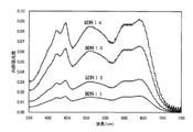
- FIG. 8 shows the internal absorbance spectrum of the measurement samples 11 to 14
- FIG. 9 shows the internal transmittance spectrum of the measurement samples 11 to 14.
- ⁇ Evaluation of haze> In order to evaluate the haze (cloudiness value) of the light diffusion layer, a polymer film (sample for haze measurement) in which only alumina fine particles having the same concentration (average particle diameter 1.1 ⁇ m) were added without adding an organic dye was prepared. did.
- a polymer film sample for haze measurement
- polymethyl methacrylate and alumina fine particles were added to methylene chloride, and stirred uniformly to prepare a dispersion. 10 mass parts of alumina fine particles were added with respect to 100 mass parts of polymethyl methacrylate.
- a sample for haze measurement having a thickness of about 30 ⁇ m was obtained by applying this dispersion onto a stainless steel substrate having a smooth surface and volatilizing the solvent.
- this haze measurement sample was measured with a haze meter (Nippon Denshoku Industries Co., Ltd., NDH2000), the haze was about 91%.
- the light diffusing layers 11 to 14 were applied to the transmissive liquid crystal display device having the configuration shown in FIG. 7 for evaluation.
- a VA type liquid crystal panel was used, and cold cathode tubes having principal wavelengths of about 435 nm, about 545 nm, and about 615 nm were used as a backlight light source.
- the screen was illuminated with a fluorescent lamp from about 45 degrees obliquely in front of the screen so that the illuminance was about 100 lx, which was about the same level as a general living room, and the whitening of the screen was evaluated.
- the screen was displayed in black during the evaluation. As a result, whitening was reduced as the sample had higher internal absorbance. If the internal absorbance is 0.014, it is practical, and if it is 0.028 or more, almost no whitening is observed. Particularly, samples 13 and 14 of 0.055 or more displayed good black.
- a conventional liquid crystal panel provided with this viewing angle compensation film is a commercially available liquid crystal display, does not have a light diffusion layer, and does not have a layer to which a colorant as in the present invention is added. Since the screen of a conventional liquid crystal panel provided with a viewing angle compensation film has a full width at half maximum of the luminance angle distribution of about 70 degrees, the above results provide a sufficient viewing angle while using a highly directional backlight. Therefore, it was confirmed that the brightness angle distribution width necessary for this purpose was obtained.
- the front luminance decreased as the concentration of the organic dye added increased. If the internal absorbance at the main wavelength of the light emitted from the backlight light source is 0.062 or less, the front luminance and luminance angle distribution width equal to or higher than the screen of a conventional liquid crystal panel having a viewing angle compensation film can be obtained. ing.
- a conventional liquid crystal having a viewing angle compensation film as shown in FIG. 10 is formed by forming a light diffusion layer in which the internal absorbance at a main wavelength of light emitted from a backlight light source is about 0.062 or less.
- a liquid crystal display having a front luminance and a luminance angle distribution width equal to or higher than the panel screen was obtained.
- good characteristics were obtained in a light diffusion layer having an internal absorbance in the range of 0.028 to 0.062 at the main wavelength of light emitted from a backlight light source.
- image blurring due to the light diffusion layer hardly occurred.
- a viewing angle almost equivalent to the screen of a conventional liquid crystal panel including the viewing angle compensation film as shown in FIG. 10 was obtained.
- Example 2 ⁇ Preparation of light diffusion layer> Single-layered light diffusion layers 21 to 24 as shown in FIG. 4 were produced by the following method. First, a transparent protective layer was prepared in the same manner as in Example 1. On the other hand, the same polymethylmethacrylate, red, blue and yellow organic dyes as in Example 1 were added to methylene chloride, and melamine / formaldehyde condensate fine particles (average particle size 1.3 ⁇ m) were further added. And a dispersion was prepared. The red, blue and yellow organic dyes were added so as to have the concentrations (mass%) shown in Table 4 below with respect to polymethyl methacrylate.
- melamine formaldehyde condensate fine particles were added with respect to 100 mass parts of polymethyl methacrylate.
- the methylene chloride concentration was appropriately adjusted so that a light diffusion layer having a desired thickness was obtained and coating was easy.
- This dispersion was applied to the transparent protective layer to obtain a light diffusion layer having a thickness of about 30 ⁇ m.
- the added light transmissive fine particles (melamine / formaldehyde condensate fine particles) are on one surface in the light diffusing layer as shown in FIG. It was confirmed that it was biased to the side.
- ⁇ Evaluation of haze> In order to evaluate the haze of the light diffusing layer, a polymer film having a film thickness of about 30 ⁇ m (only a melamine / formaldehyde condensate fine particle having the same concentration (average particle size 1.3 ⁇ m) is added without adding an organic dye ( Sample for haze measurement) was prepared.
- the method for producing the sample for haze measurement is in accordance with the method for producing the sample for haze measurement in Example 1. When the produced haze measurement sample was measured with a haze meter (Nippon Denshoku Industries Co., Ltd., NDH2000), the haze was about 94%.
- the light diffusing layers 21 to 24 were added to the transmissive liquid crystal display element having the configuration shown in FIG. 7 to evaluate the light diffusing layers.
- the liquid crystal panel was a VA type, and a cold cathode tube having principal wavelengths of about 435 nm, about 545 nm, and about 615 nm was used as the backlight.
- the screen was illuminated with a fluorescent lamp from about 45 degrees obliquely in front of the screen so that the illuminance was about 100 lx, which was about the same level as a general living room, and the whitening of the screen was evaluated.
- the screen was displayed in black. As a result, whitening was reduced as the sample had higher internal absorbance.
- the internal absorbance at the main wavelength of the light emitted from the backlight light source is 0.014, it is practical, and if it is 0.028 or more, whitening is hardly observed, and in particular, it is emitted from the backlight light source. Good black was displayed for Sample 23 and Sample 24 having an internal absorbance of 0.055 or more at the main wavelength of light.
- the screen of a conventional liquid crystal panel provided with a viewing angle compensation film has a full width at half maximum of the luminance angle distribution of about 70 degrees, the above results provide a sufficient viewing angle while using a highly directional backlight. Therefore, it was confirmed that the brightness angle distribution width necessary for this purpose was obtained.
- the front luminance decreased as the concentration of the organic dye added increased. If the internal absorbance at the main wavelength of the light emitted from the backlight light source is 0.062 or less, the front luminance and luminance angle distribution width equal to or higher than the screen of a conventional liquid crystal panel having a viewing angle compensation film can be obtained. ing.
- the light-transmitting polymer has a colorant on the outer side (observer side) of the light-diffusing layer having the laminated structure as shown in FIG. A layer in which a colored layer 18 to which is added was laminated was produced. Triacetyl cellulose was selected as the translucent polymer.
- the red, blue and yellow organic dyes were added so as to have the concentrations (mass%) shown in Table 6 below with respect to triacetylcellulose.
- the methylene chloride concentration was appropriately adjusted so that the desired film thickness was obtained and coating was easy.
- the dispersion liquid-1 was applied to the transparent protective layer prepared in the same manner as in Example 1 to obtain a scattering layer 16 having a thickness of about 30 ⁇ m. Further, the solution-1 was applied on the scattering layer 16 to form a colored layer 18 having a thickness of about 30 ⁇ m, and light diffusion layers 31 to 34 were obtained.
- ⁇ Evaluation of haze> In order to evaluate the haze of the light diffusion layer, a film (haze measurement sample) having the same composition as that of the scattering layer 16 of Example 3 was prepared.
- the method for producing the sample for haze measurement is in accordance with the method for producing the sample for haze measurement in Example 1.
- the produced haze measurement sample was measured with a haze meter (Nippon Denshoku Industries Co., Ltd., NDH2000), the haze was about 92%.
- the light scattering layers 31 to 34 were applied to the transmissive liquid crystal display element having the configuration shown in FIG. 7 to evaluate the light diffusion layer.
- the liquid crystal panel was a VA type, and a cold cathode tube having principal wavelengths of about 435 nm, about 545 nm, and about 615 nm was used as the backlight.
- the screen was illuminated with a fluorescent lamp from about 45 degrees obliquely in front of the screen so that the illuminance was about 100 lx, which was about the same level as a general living room, and the whitening of the screen was evaluated.
- the screen was displayed in black. As a result, whitening was reduced as the sample had higher internal absorbance.
- the luminance distribution (Topcon Co., Ltd., BM-7FAST) was used to measure the front luminance and the angular distribution of luminance in the horizontal direction. The measurement was performed with the screen displayed in white.
- the angular distribution of the luminance before entering the liquid crystal panel of the backlight used (equivalent to before entering the transparent protective layer 26 in FIG. 7) had a full width at half maximum of about 30 degrees. The light from the backlight passed through the liquid crystal panel and was diffused by the frontmost light diffusion layer. As a result, the full width at half maximum was about 70 degrees in any of the light diffusion layers.
- the screen of a conventional liquid crystal panel equipped with a viewing angle compensation film has a full width at half maximum of the luminance angle distribution of about 70 degrees, so that a sufficient viewing angle can be obtained while using a highly directional backlight. It was confirmed that it had the necessary angular distribution width of luminance.
- the front luminance was lower as the concentration of the organic dye added was higher. If the internal absorbance at the main wavelength of the light emitted from the backlight light source is 0.062 or less, the front luminance and luminance angle distribution width equal to or higher than the screen of a conventional liquid crystal panel having a viewing angle compensation film can be obtained. ing.
- a viewing angle almost equivalent to the screen of a conventional liquid crystal panel including the viewing angle compensation film as shown in FIG. 10 can be obtained regardless of the configuration in which the viewing angle compensation film is not used. It was. Further, according to Examples 1 to 3, by forming a light diffusion layer corresponding to a range in which the internal absorbance at the main wavelength of the light emitted from the backlight light source is about 0.062 or less, whitening is favorably reduced.
- a liquid crystal display having a front luminance and a luminance angle distribution width comparable to or higher than that of a screen of a conventional liquid crystal panel provided with a viewing angle compensation film as shown in FIG. 10 could be obtained.
- Example 4 ⁇ Preparation of light diffusion layer> The light diffusion layers 41 to 45 were produced by the method as described below.
- a transparent protective layer was prepared in the same manner as in Example 1.
- CIPigment Red 48 3 (Sanyo Dye Co., Ltd.)
- CIPigment Blue 15 1 (Copper Compound) (Sanyo Dye Co., Ltd.)
- CIPigment Yellow 14 Sanyo Dyeing Co., Ltd.
- alumina fine particles average particle size 1.1 ⁇ m
- the red, blue and yellow organic pigments were added so as to have the concentration (mass%) shown in Table 8 below with respect to polymethyl methacrylate.
- the alumina fine particles were added so as to be 5 parts by mass with respect to 100 parts by mass of polymethyl methacrylate.
- the dispersion was appropriately adjusted in ethyl acetate concentration so that a light diffusion layer having a desired thickness was obtained and coating was easy. This dispersion was applied to the transparent protective layer to obtain light diffusion layers 41 to 45 having a thickness of about 30 ⁇ m.
- Films (measurement samples 41 to 45) having a composition in which only the alumina fine particles were removed from the light diffusion layer having the above composition were prepared for measuring internal absorbance, internal attenuation, and internal transmittance.
- the production method of the measurement samples 41 to 45 is in accordance with the production method of the measurement samples 11 to 14 in Example 1. These films were measured for internal absorbance, internal attenuation, and internal transmittance using a commercially available spectrophotometer.
- ⁇ Evaluation of haze> In order to evaluate the haze of the light diffusing layer, a polymer film having a film thickness of about 30 ⁇ m (sample for haze measurement) in which only the alumina fine particles having the same concentration (average particle diameter 1.1 ⁇ m) are added without adding an organic dye. ) was produced.
- the method for producing the sample for haze measurement is in accordance with the method for producing the sample for haze measurement in Example 1. When the produced haze measurement sample was measured with a haze meter (Nippon Denshoku Industries Co., Ltd., NDH2000), the haze was about 77%.
- the light scattering layers 41 to 45 were added to the transmissive liquid crystal display element having the configuration shown in FIG. 7 to evaluate the light diffusion layer.
- An IPS type liquid crystal panel was used, and cold cathode tubes having principal wavelengths of about 435 nm, about 545 nm, and about 615 nm were used as the backlight.
- the screen was illuminated with a fluorescent lamp from 45 degrees obliquely in front of the screen to evaluate the whitening of the screen so that the illuminance is about 100 lx, which is about the same level as a general living room. During the evaluation, the screen was displayed in black. As a result, whitening was reduced as the sample had higher internal absorbance.
- the internal absorbance at the main wavelength of the light emitted from the backlight source is 0.014, it is practical, and if it is 0.020 or more, almost no whitening is observed, and in particular, it is emitted from the backlight source.
- the luminance angle distribution was measured in the same manner as in Example 1.
- the luminance angle distribution measurement samples 41 and 42 as the light diffusion layer used for the measurement of the luminance angle distribution were added with an organic pigment in the amount shown in the sample 43 of Table 8 above, and the alumina fine particles were added to 100 mass of polymethyl methacrylate. It is added so that it may become 5 mass parts or 10 mass parts with respect to a part.
- the luminance angle distribution before entering the liquid crystal panel of the backlight used (corresponding to before entering the transparent protective layer 26 in FIG. 7) had a full width at half maximum of about 47 degrees. As a result of the light from this backlight passing through the liquid crystal panel and being diffused by the frontmost light diffusion layer, as shown in Table 9, the full width at half maximum was about 70 degrees or more in any of the light diffusion layers. .
- the screen of the conventional liquid crystal panel provided with the viewing angle compensation film has a full width at half maximum of the luminance angle distribution of about 70 degrees, when a backlight having a full width at half maximum of the luminance angle distribution of 47 degrees is used, the luminance It was confirmed that the angular distribution measurement sample 41 has an angular distribution width of luminance necessary for obtaining a sufficient viewing angle.
- Example 4 when a backlight having a full width at half maximum of about 47 degrees in the luminance angle distribution is used, the internal absorbance at the main wavelength of the light emitted from the backlight source corresponds to a range of about 0.020 or more.
- the light diffusion layer By forming the light diffusion layer, whitening was satisfactorily reduced, the viewing angle was sufficiently widened, and the full width at half maximum of luminance was about 70 degrees or more.
- good characteristics were obtained when the internal absorbance at the main wavelength of light emitted from the backlight source was 0.029 or more. Further, in the liquid crystal display having the light diffusion layer of Example 4, image blurring due to the light diffusion layer hardly occurred.
- Example 5 ⁇ Preparation of a light diffusion layer that also serves as a protective layer> A light diffusion layer 51 that also serves as a protective layer was produced by the method described below. The same polymethylmethacrylate and red, blue and yellow organic pigments as in Example 4 were added to ethyl acetate, and alumina fine particles (average particle size 1.1 ⁇ m) were further added, and the mixture was stirred and dispersed uniformly. A liquid was prepared. The alumina fine particles were added so as to be 20 parts by mass with respect to 100 parts by mass of polymethyl methacrylate.
- CIPigment Red 48 3 (Sanyo Dye Co., Ltd.), CIPigment Blue 15: 1 (Copper Compound) (Sanyo Dye Co., Ltd.), CIPigment Yellow 14 (Sanyo Dye Co., Ltd.) )It was used.
- the red, blue, and yellow organic pigments were added to 0.392 parts by mass, 0.072 parts by mass, and 0.120 parts by mass, respectively, with respect to 100 parts by mass of polymethyl methacrylate.
- the dispersion was applied on a stainless steel substrate having a smooth surface, and the solvent was roughly dried to prepare a film sample.
- the obtained film sample was pulverized and further dried under reduced pressure.
- the obtained sample was mixed with 3 times the amount of polymethylmethacrylate pellets, kneaded using a twin screw extruder at 230 ° C., and then extruded into a film using a single screw extruder at 270 ° C. I wound up with.
- the light diffusion layer 51 also serving as the protective layer was produced.
- the light diffusing layer 51 that also serves as the protective layer of Example 5 is the same as the light diffusing layer 42 of Example 4 in the organic dye concentration and the addition amount of the alumina fine particles. It is thought that the same effect is produced.
- a light diffusion layer 61 that also serves as a pressure-sensitive adhesive layer was produced by the method described below.
- a solution having a concentration of about 30% by mass was prepared.
- Coronate L manufactured by Nippon Polyurethane Co., Ltd. which is an isocyanate-based polyfunctional compound, is added to the acrylic polymer solution in an amount of 4 parts by mass with respect to 100 parts by mass of polymer solids, and additives (KBM403, manufactured by Shin-Etsu Chemical Co., Ltd.) 5 parts by mass, 5 parts by mass of alumina fine particles (average particle size 1.1 ⁇ m), and red, blue and yellow organic pigments were added to prepare an adhesive solution.
- additives KBM403, manufactured by Shin-Etsu Chemical Co., Ltd.
- CIPigment Red 48 3 (Sanyo Dye Co., Ltd.)
- CIPigment Blue 15 1 (Copper Compound) (Sanyo Dye Co., Ltd.)
- CIPigment Yellow 14 Sanyo Dye Co., Ltd.
- the red, blue and yellow organic pigments were added to 0.098 parts by mass, 0.018 parts by mass and 0.030 parts by mass with respect to 100 parts by mass of the copolymer.
- a solvent for adjusting viscosity (ethyl acetate) is added, and the pressure-sensitive adhesive solution is placed on a release film (polyethylene terephthalate substrate: Diafoil MRF38, manufactured by Mitsubishi Chemical Polyester) so that the thickness after drying is 25 ⁇ m. After the application, it was dried in a hot air circulation oven to form an adhesive layer containing a scatterer and a colorant. The polarizing film 28 and the outer transparent protective layer 26 were bonded together using this pressure-sensitive adhesive layer.
- a release film polyethylene terephthalate substrate: Diafoil MRF38, manufactured by Mitsubishi Chemical Polyester
- the light diffusing layer 61 that also serves as the adhesive layer of Example 6 is the same as the light diffusing layer 42 of Example 4 in the organic dye concentration and the addition amount of the alumina fine particles. It is thought that the same effect is produced.
Landscapes
- Physics & Mathematics (AREA)
- General Physics & Mathematics (AREA)
- Optics & Photonics (AREA)
- Nonlinear Science (AREA)
- Mathematical Physics (AREA)
- Chemical & Material Sciences (AREA)
- Crystallography & Structural Chemistry (AREA)
- Liquid Crystal (AREA)
- Optical Elements Other Than Lenses (AREA)
Abstract
Priority Applications (3)
| Application Number | Priority Date | Filing Date | Title |
|---|---|---|---|
| CN201080025580.XA CN102460286B (zh) | 2009-06-09 | 2010-05-31 | 透射型液晶显示装置及光扩散板 |
| KR1020127000259A KR101375400B1 (ko) | 2009-06-09 | 2010-05-31 | 투과형 액정표시장치 및 광확산판 |
| JP2011518441A JP5323190B2 (ja) | 2009-06-09 | 2010-05-31 | 透過型液晶表示装置および光拡散板 |
Applications Claiming Priority (2)
| Application Number | Priority Date | Filing Date | Title |
|---|---|---|---|
| JP2009-138442 | 2009-06-09 | ||
| JP2009138442 | 2009-06-09 |
Publications (1)
| Publication Number | Publication Date |
|---|---|
| WO2010143552A1 true WO2010143552A1 (fr) | 2010-12-16 |
Family
ID=43308807
Family Applications (1)
| Application Number | Title | Priority Date | Filing Date |
|---|---|---|---|
| PCT/JP2010/059216 Ceased WO2010143552A1 (fr) | 2009-06-09 | 2010-05-31 | Dispositif d'affichage à cristaux liquides du type à transmission |
Country Status (5)
| Country | Link |
|---|---|
| JP (1) | JP5323190B2 (fr) |
| KR (1) | KR101375400B1 (fr) |
| CN (1) | CN102460286B (fr) |
| TW (1) | TWI425275B (fr) |
| WO (1) | WO2010143552A1 (fr) |
Cited By (4)
| Publication number | Priority date | Publication date | Assignee | Title |
|---|---|---|---|---|
| CN104145215A (zh) * | 2012-03-02 | 2014-11-12 | 三菱制纸株式会社 | 透射型屏幕 |
| CN109960082A (zh) * | 2019-05-05 | 2019-07-02 | 京东方科技集团股份有限公司 | 场序显示模组、显示装置及场序显示控制方法 |
| WO2020178922A1 (fr) * | 2019-03-01 | 2020-09-10 | シャープ株式会社 | Dispositif d'affichage |
| WO2024172011A1 (fr) * | 2023-02-16 | 2024-08-22 | リンテック株式会社 | Feuille adhésive, stratifié et corps d'affichage |
Families Citing this family (3)
| Publication number | Priority date | Publication date | Assignee | Title |
|---|---|---|---|---|
| CN104898197A (zh) * | 2015-04-29 | 2015-09-09 | 京东方科技集团股份有限公司 | 一种导光板及其制备方法、背光模组和显示装置 |
| WO2020194720A1 (fr) * | 2019-03-28 | 2020-10-01 | 堺ディスプレイプロダクト株式会社 | Film de diffusion de lumière et dispositif d'affichage à cristaux liquides |
| WO2020194719A1 (fr) | 2019-03-28 | 2020-10-01 | 堺ディスプレイプロダクト株式会社 | Dispositif d'affichage à cristaux liquides |
Citations (6)
| Publication number | Priority date | Publication date | Assignee | Title |
|---|---|---|---|---|
| JPH03116021A (ja) * | 1989-09-28 | 1991-05-17 | Toshiba Corp | 液晶表示装置 |
| JP2001215494A (ja) * | 2000-01-31 | 2001-08-10 | Fuji Photo Film Co Ltd | 液晶ディスプレイ及びその高コントラスト化及び広視野角化方法 |
| JP2002215057A (ja) * | 2001-01-16 | 2002-07-31 | Nec Corp | ディスプレイ用フィルタ |
| JP2005037738A (ja) * | 2003-07-16 | 2005-02-10 | Nitto Denko Corp | 粒子分散系樹脂シート、画像表示装置用基板および画像表示装置 |
| JP2006064908A (ja) * | 2004-08-26 | 2006-03-09 | Fuji Photo Film Co Ltd | 透過型カラー液晶表示装置 |
| JP2006208647A (ja) * | 2005-01-27 | 2006-08-10 | Fuji Photo Film Co Ltd | 透過型カラー液晶表示装置 |
Family Cites Families (3)
| Publication number | Priority date | Publication date | Assignee | Title |
|---|---|---|---|---|
| JP3517975B2 (ja) * | 1994-08-12 | 2004-04-12 | ソニー株式会社 | 液晶表示装置及びその製造方法 |
| JP3760635B2 (ja) * | 1998-08-21 | 2006-03-29 | セイコーエプソン株式会社 | 液晶表示装置及びそれを用いた電子機器 |
| TWI275835B (en) * | 2002-10-08 | 2007-03-11 | Nitto Denko Corp | Polarizer, optical film, and image display |
-
2010
- 2010-05-31 WO PCT/JP2010/059216 patent/WO2010143552A1/fr not_active Ceased
- 2010-05-31 KR KR1020127000259A patent/KR101375400B1/ko active Active
- 2010-05-31 CN CN201080025580.XA patent/CN102460286B/zh active Active
- 2010-05-31 JP JP2011518441A patent/JP5323190B2/ja active Active
- 2010-06-04 TW TW099118267A patent/TWI425275B/zh active
Patent Citations (6)
| Publication number | Priority date | Publication date | Assignee | Title |
|---|---|---|---|---|
| JPH03116021A (ja) * | 1989-09-28 | 1991-05-17 | Toshiba Corp | 液晶表示装置 |
| JP2001215494A (ja) * | 2000-01-31 | 2001-08-10 | Fuji Photo Film Co Ltd | 液晶ディスプレイ及びその高コントラスト化及び広視野角化方法 |
| JP2002215057A (ja) * | 2001-01-16 | 2002-07-31 | Nec Corp | ディスプレイ用フィルタ |
| JP2005037738A (ja) * | 2003-07-16 | 2005-02-10 | Nitto Denko Corp | 粒子分散系樹脂シート、画像表示装置用基板および画像表示装置 |
| JP2006064908A (ja) * | 2004-08-26 | 2006-03-09 | Fuji Photo Film Co Ltd | 透過型カラー液晶表示装置 |
| JP2006208647A (ja) * | 2005-01-27 | 2006-08-10 | Fuji Photo Film Co Ltd | 透過型カラー液晶表示装置 |
Cited By (7)
| Publication number | Priority date | Publication date | Assignee | Title |
|---|---|---|---|---|
| CN104145215A (zh) * | 2012-03-02 | 2014-11-12 | 三菱制纸株式会社 | 透射型屏幕 |
| US9360747B2 (en) | 2012-03-02 | 2016-06-07 | Mitsubishi Paper Mills Limited | Transmission type screen |
| CN107037514A (zh) * | 2012-03-02 | 2017-08-11 | 三菱制纸株式会社 | 可透视的透射型屏幕 |
| WO2020178922A1 (fr) * | 2019-03-01 | 2020-09-10 | シャープ株式会社 | Dispositif d'affichage |
| CN109960082A (zh) * | 2019-05-05 | 2019-07-02 | 京东方科技集团股份有限公司 | 场序显示模组、显示装置及场序显示控制方法 |
| CN109960082B (zh) * | 2019-05-05 | 2022-06-07 | 京东方科技集团股份有限公司 | 场序显示模组、显示装置及场序显示控制方法 |
| WO2024172011A1 (fr) * | 2023-02-16 | 2024-08-22 | リンテック株式会社 | Feuille adhésive, stratifié et corps d'affichage |
Also Published As
| Publication number | Publication date |
|---|---|
| JP5323190B2 (ja) | 2013-10-23 |
| TW201116893A (en) | 2011-05-16 |
| KR101375400B1 (ko) | 2014-03-17 |
| KR20120026601A (ko) | 2012-03-19 |
| TWI425275B (zh) | 2014-02-01 |
| CN102460286A (zh) | 2012-05-16 |
| JPWO2010143552A1 (ja) | 2012-11-22 |
| CN102460286B (zh) | 2015-04-01 |
Similar Documents
| Publication | Publication Date | Title |
|---|---|---|
| CN100594406C (zh) | 反射偏振片和具有该反射偏振片的显示装置 | |
| JP5323190B2 (ja) | 透過型液晶表示装置および光拡散板 | |
| JP6120481B2 (ja) | 光制御フィルム及び多層光学フィルムスタック | |
| JP2011039093A (ja) | 液晶表示装置および液晶表示装置用光学部材セット | |
| TWI582472B (zh) | 偏光元件及偏光板 | |
| WO2004023173A1 (fr) | Polariseur, film optique et afficheur d'images | |
| JP6329107B2 (ja) | 液晶表示装置用色純度向上フィルム及びこれを含む液晶表示装置 | |
| JP2007206674A (ja) | 光学薄膜シート | |
| KR100950887B1 (ko) | 광학 장치, 화상 표시장치 및 액정 표시장치 | |
| CN101630032B (zh) | 反射式偏光片 | |
| JP2005283800A (ja) | 楕円偏光板、光学フィルムおよび画像表示装置 | |
| JP2005292225A (ja) | 光学フィルムおよび画像表示装置 | |
| JP7389792B2 (ja) | 光学積層体および液晶表示装置 | |
| US20080186428A1 (en) | Optical apparatus, image display, and liquid crystal display | |
| JP2006063195A (ja) | 粘着シート | |
| JPWO2008129946A1 (ja) | 光拡散フィルムおよびそれを用いた液晶バックライトユニット | |
| US20070159580A1 (en) | Polarizing plate, optical film and image display | |
| KR20160094885A (ko) | 색변환 필름 및 이를 포함하는 백라이트 유닛 | |
| JP6627298B2 (ja) | 量子ドットシート、バックライト及び液晶表示装置 | |
| JP2002006400A (ja) | 透過型スクリーン | |
| JP2008139832A (ja) | 液晶ディスプレイ及びこれに用いられる光学素子 | |
| TW201329545A (zh) | 液晶顯示裝置 | |
| JP2005202368A (ja) | 偏光板、光学フィルムおよび画像表示装置 | |
| JP2014186044A (ja) | 表示装置 | |
| JP2005202146A (ja) | 偏光子の製造方法、偏光板の製造方法、積層光学フィルムの製造方法、偏光子、偏光板、積層光学フィルムおよび画像表示装置 |
Legal Events
| Date | Code | Title | Description |
|---|---|---|---|
| WWE | Wipo information: entry into national phase |
Ref document number: 201080025580.X Country of ref document: CN |
|
| 121 | Ep: the epo has been informed by wipo that ep was designated in this application |
Ref document number: 10786083 Country of ref document: EP Kind code of ref document: A1 |
|
| DPE2 | Request for preliminary examination filed before expiration of 19th month from priority date (pct application filed from 20040101) | ||
| WWE | Wipo information: entry into national phase |
Ref document number: 2011518441 Country of ref document: JP |
|
| NENP | Non-entry into the national phase |
Ref country code: DE |
|
| ENP | Entry into the national phase |
Ref document number: 20127000259 Country of ref document: KR Kind code of ref document: A |
|
| 122 | Ep: pct application non-entry in european phase |
Ref document number: 10786083 Country of ref document: EP Kind code of ref document: A1 |