WO2010143555A1 - Unité d'excitation, sonde ultrasonore et équipement de diagnostic à ultrasons - Google Patents
Unité d'excitation, sonde ultrasonore et équipement de diagnostic à ultrasons Download PDFInfo
- Publication number
- WO2010143555A1 WO2010143555A1 PCT/JP2010/059241 JP2010059241W WO2010143555A1 WO 2010143555 A1 WO2010143555 A1 WO 2010143555A1 JP 2010059241 W JP2010059241 W JP 2010059241W WO 2010143555 A1 WO2010143555 A1 WO 2010143555A1
- Authority
- WO
- WIPO (PCT)
- Prior art keywords
- vibration
- ultrasonic probe
- ultrasonic
- mounting member
- lock
- Prior art date
- Legal status (The legal status is an assumption and is not a legal conclusion. Google has not performed a legal analysis and makes no representation as to the accuracy of the status listed.)
- Ceased
Links
Images






Classifications
-
- A—HUMAN NECESSITIES
- A61—MEDICAL OR VETERINARY SCIENCE; HYGIENE
- A61B—DIAGNOSIS; SURGERY; IDENTIFICATION
- A61B8/00—Diagnosis using ultrasonic, sonic or infrasonic waves
- A61B8/08—Clinical applications
-
- A—HUMAN NECESSITIES
- A61—MEDICAL OR VETERINARY SCIENCE; HYGIENE
- A61B—DIAGNOSIS; SURGERY; IDENTIFICATION
- A61B8/00—Diagnosis using ultrasonic, sonic or infrasonic waves
- A61B8/48—Diagnostic techniques
- A61B8/485—Diagnostic techniques involving measuring strain or elastic properties
-
- G—PHYSICS
- G01—MEASURING; TESTING
- G01S—RADIO DIRECTION-FINDING; RADIO NAVIGATION; DETERMINING DISTANCE OR VELOCITY BY USE OF RADIO WAVES; LOCATING OR PRESENCE-DETECTING BY USE OF THE REFLECTION OR RERADIATION OF RADIO WAVES; ANALOGOUS ARRANGEMENTS USING OTHER WAVES
- G01S7/00—Details of systems according to groups G01S13/00, G01S15/00, G01S17/00
- G01S7/52—Details of systems according to groups G01S13/00, G01S15/00, G01S17/00 of systems according to group G01S15/00
- G01S7/52017—Details of systems according to groups G01S13/00, G01S15/00, G01S17/00 of systems according to group G01S15/00 particularly adapted to short-range imaging
- G01S7/52023—Details of receivers
- G01S7/52036—Details of receivers using analysis of echo signal for target characterisation
- G01S7/52042—Details of receivers using analysis of echo signal for target characterisation determining elastic properties of the propagation medium or of the reflective target
-
- G—PHYSICS
- G01—MEASURING; TESTING
- G01S—RADIO DIRECTION-FINDING; RADIO NAVIGATION; DETERMINING DISTANCE OR VELOCITY BY USE OF RADIO WAVES; LOCATING OR PRESENCE-DETECTING BY USE OF THE REFLECTION OR RERADIATION OF RADIO WAVES; ANALOGOUS ARRANGEMENTS USING OTHER WAVES
- G01S7/00—Details of systems according to groups G01S13/00, G01S15/00, G01S17/00
- G01S7/52—Details of systems according to groups G01S13/00, G01S15/00, G01S17/00 of systems according to group G01S15/00
- G01S7/52017—Details of systems according to groups G01S13/00, G01S15/00, G01S17/00 of systems according to group G01S15/00 particularly adapted to short-range imaging
- G01S7/52079—Constructional features
-
- A—HUMAN NECESSITIES
- A61—MEDICAL OR VETERINARY SCIENCE; HYGIENE
- A61B—DIAGNOSIS; SURGERY; IDENTIFICATION
- A61B8/00—Diagnosis using ultrasonic, sonic or infrasonic waves
Definitions
- the present invention relates to an excitation unit, an ultrasonic probe, and an ultrasonic diagnostic apparatus, and in particular, to measure vibration information on a subject in order to measure elasticity information representing the hardness or softness of a biological tissue of the subject.
- the present invention relates to an excitation unit used for raising a shear wave by applying, an ultrasonic probe provided with the excitation unit, and an ultrasonic diagnostic apparatus.
- Ultrasonic diagnostic equipment transmits ultrasonic waves to biological tissues and the like with an ultrasonic inspection probe, receives ultrasonic reflected echo signals according to the structure, and constructs tomographic images such as ultrasonic tomographic images And display for diagnosis.
- Patent Document 1 proposes a mechanism for compressing a subject using a mechanical method.
- a low frequency (about 1 kHz) vibration (impact) is applied to the subject to raise a wave called a shear wave, and by measuring the propagation speed of the shear wave, the biological tissue of the subject is measured.
- elasticity information that is, in general, the propagation speed of shear waves correlates with the elasticity of the propagating medium, and it is known that when the medium is hard, the propagation speed of the shear wave is fast, and conversely, when the medium is soft, it is slow.
- elasticity information of the living tissue of the subject can be obtained based on the propagation speed of the shear wave.
- the conventional technology measures the elasticity information of the subject based on the propagation velocity of the shear wave using a general-purpose ultrasonic probe capable of rendering an ultrasonic tomographic image, and applies the ultrasonic wave to the ultrasonic wave due to electromagnetic noise. Suppressing the impact is not considered.
- Patent Document 1 obtains elastic information from displacement information obtained by directly compressing the biological tissue or the like of a subject through an ultrasonic probe by a mechanical compression mechanism, It is not considered to obtain elastic information from the shear waves that are generated.
- Patent Document 2 describes a technique for obtaining elasticity information from a shear wave raised by vibration, but uses a dedicated probe to measure the propagation speed of the shear wave.
- a dedicated probe of Patent Document 2 When the dedicated probe of Patent Document 2 is used alone, an ultrasonic tomographic image of the subject cannot be drawn. Therefore, in order to perform multiple measurements on the same cross section, a separate ultrasonic diagnostic apparatus is used. It takes time and effort because it is necessary to determine the measurement cross section.
- an electrodynamic actuator as described in Patent Document 2 into a general-purpose ultrasonic probe capable of rendering an ultrasonic tomographic image. Since it affects sound waves, it is not preferable.
- the elasticity information of the subject based on the propagation speed of the shear wave is measured using a general-purpose ultrasonic probe capable of rendering an ultrasonic tomographic image, and the influence of electromagnetic noise on the ultrasonic wave is measured. It is a problem to suppress.
- the vibration unit of the present invention that solves the above problems is provided with a mounting member that is detachably mounted on an ultrasonic probe, a guide rail that is provided on the mounting member, and a slide that is slidable along the guide rail.
- the vibration member a stopper for restricting the sliding of the vibration member, an elastic member provided so that the vibration member is slid and stored in a direction away from the stopper, and the vibration member is stored.
- a lock mechanism that locks the vibration member at the biased position and a lock release mechanism that unlocks the lock mechanism are configured.
- the excitation unit of the present invention is mounted on a general-purpose ultrasonic probe capable of rendering an ultrasonic tomogram, and the excitation member is slid along the guide rail and locked at the accumulated position.
- the vibration member is locked by the mechanism and the lock is released by the lock release mechanism, the vibration member is urged by the elastic member and collides with the stopper.
- the vibration (impact) at this time can propagate to the subject through the excitation unit and can raise the shear wave.
- the propagation speed of a shear wave Elasticity information based on can be measured.
- the vibration is generated with a mechanical configuration that causes the vibration member to collide with the stopper, the influence of electromagnetic noise on the ultrasonic wave is suppressed compared to the case where vibration is generated using an electrodynamic actuator. can do.
- the excitation unit is formed so that the mounting member is mounted so as to cover the outer periphery of the grip portion of the ultrasonic probe, and the inner surface of the mounting member is arranged in the axial direction of the ultrasonic probe.
- a guide rail may be formed along the guide rail, and the vibration member may be provided to cover the outer periphery of the grip portion of the ultrasonic probe so as to be slidable on the guide rail.
- a vibration unit comprising a mounting member, a guide rail, a vibration member, and other members can be integrally formed. According to this, while an excitation unit corresponding to each of various types of general-purpose ultrasonic probes is required, the excitation unit can be reduced in size, so that the ultrasonic probe for diagnosis can be reduced. The child is preferably handled easily.
- the elastic member can be configured by a spring member having one end fixed to the mounting member and the other end fixed to the vibration member, and a pair of spring members sandwiching the grip portion of the ultrasonic probe. According to this, since both sides of the vibration member sandwiching the grip portion of the ultrasonic probe are urged by the spring member, it is possible to avoid the vibration member from tilting and colliding with the stopper.
- the locking mechanism includes a pair of vertical slits formed along the axial direction of the ultrasonic probe on opposite surfaces of the mounting member that sandwich the grip portion of the ultrasonic probe, and a part of the long side of the vertical slit. From the vertical slit of the mounting member, a horizontal slit formed in a direction perpendicular to the vertical slit from the vertical slit of the mounting member It can be configured to have an operation protrusion that protrudes and is slidable in the direction of the lateral slit of the mounting member with respect to the vibration member. Further, a plurality of lateral slits of the mounting member can be formed with respect to the long side of the vertical slit of the mounting member.
- the operating protrusion is slid along the vertical slit of the mounting member to slide the vibration member to the setting position of the guide rail, and the operating protrusion is slid along the horizontal slit of the mounting member to
- the vibrating member can be locked by engaging with the slit.
- the vibration member can be locked at a plurality of set positions of the guide rail by forming a plurality of lateral slits. This is preferable because the lock position of the vibration member can be adjusted according to the depth of the diagnostic region from the body surface of the subject.
- the lock release mechanism is provided between the outer peripheral surface of the vibration member and the inner peripheral surface of the mounting member, and one end of the vertical slit of the pair of operation protrusions of the vibration member that is locked to the horizontal slit of the mounting member.
- a pair of release arms formed in contact with the opposite surface and extending in the direction along the horizontal slit, and connected to the other ends of the pair of release arms, the other end is pressed in the direction along the horizontal slit.
- a release protrusion formed so as to protrude from the mounting member is possible.
- the examiner presses the release protrusion protruding from the mounting member, thereby moving the pair of operation protrusions of the vibration member locked to the horizontal slit via the pair of release arms in the direction of the vertical slit of the mounting member.
- the vibration member can be unlocked by sliding it.
- the examiner can easily press the release protrusion while taking an ultrasonic tomographic image, which is preferable in terms of operability.
- the release protrusion is connected to the other ends of both of the pair of release arms, the lock is released simultaneously by sliding both of the pair of operation protrusions of the vibration member simply by pressing one release protrusion. be able to. Therefore, it is possible to easily release the lock as compared with the case where each of the pair of release arms is operated separately, and it is possible to avoid the vibration member from tilting and colliding with the stopper.
- the attachment member is formed to be attached so as to cover the outer periphery of the grip portion of the ultrasonic probe, and the stopper is connected to the ultrasonic probe and the ultrasonic diagnostic apparatus. It is formed in a plate shape with a through-hole through which it can be inserted and detachably attached to the rear end of the mounting member, and the guide rail extends from the periphery of the through-hole of the stopper to cover the outer circumference of the cable of the ultrasonic probe. Can be formed.
- the mounting member corresponding to each of various types of ultrasonic probes is configured by detachably configuring a vibration unit comprising a stopper, a guide rail, a vibration member, and other members with respect to the mounting member.
- the vibration unit is preferable because it can be used in common.
- a general-purpose ultrasonic probe capable of rendering an ultrasonic tomographic image is used to measure the elasticity information of the subject based on the propagation velocity of the shear wave, and the influence of electromagnetic noise on the ultrasonic wave. Can be suppressed.
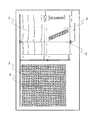
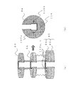
- the figure which shows the structure of the lock release mechanism Diagram explaining the operation of the vibration unit The figure explaining the vibration detection sensor provided in a vibration unit
- the figure explaining the vibration detection sensor provided in a vibration unit The figure which shows the structure of the attachment for slippage prevention of a fault plane Diagram showing a second embodiment of the vibration unit
- FIG. 1 is a block diagram showing an overall configuration of an ultrasonic diagnostic apparatus 1000 of the present embodiment that is used with the vibration unit 14 attached to the ultrasonic probe 12. As shown in FIG. 1
- the ultrasonic diagnostic apparatus 1000 includes an ultrasonic probe 12 that transmits and receives ultrasonic waves to and from the subject 10, and a transmission unit 16 that supplies transmission pulses to the ultrasonic probe 12.
- a receiving unit 18 that receives a reflected echo signal received by the ultrasound probe 12, an ultrasonic transmission / reception control unit 20 that controls the transmitting unit 16 and the receiving unit 18, and a reflected echo signal received by the receiving unit 18.
- a phasing addition unit 22 for performing phasing addition processing on the image
- a tomographic image construction unit 24 for performing various signal processing on the RF signal frame data phased and added by the phasing addition unit 22, and a monochrome scan converter 26 And.
- the frame data memory 28 that stores the RF frame signal output from the phasing adder 22, the displacement measuring unit 30 that measures the displacement generated in the living tissue of the subject 10, and the displacement measuring unit 30
- Elasticity information calculation unit 32 for obtaining strain or elastic modulus for calculating elasticity information indicating the hardness or softness of the body tissue of the subject in the continuous compression process from the displacement information, and calculation by elasticity information calculation unit 32
- An elastic image forming unit 34 that forms a color elastic image from strain or elastic modulus, and a color scan converter 36 that converts an output signal of the elastic image forming unit 34 to match the display of the image display unit.
- a line data memory 38 for storing an RF line signal, which will be described in detail later, outputted from the phasing adder 22, a shear wave propagation velocity calculator 40 for calculating the propagation velocity of the shear wave, and elasticity information from the propagation velocity.
- a shear wave elasticity information calculation unit 42 for obtaining strain information for calculation, and a shear wave image configuration unit 44 that generates a strain image based on the time axis from the strain information calculated by the shear wave elasticity information calculation unit 42.
- the output signal of the shear wave image construction unit 44 is converted by the color scan converter 36 so as to match the display on the image display unit.
- the switching addition unit 46 that superimposes the black and white tomographic image and the color elastic image, displays them in parallel, or switches them, the image display unit 48 that displays the synthesized composite image, and the subject from the excitation unit 14
- Excitation timing receiver 50 that receives a signal indicating that vibration has been applied to 10 and a signal that freezes the ultrasound diagnostic apparatus based on the output signal from the excitation timing receiver 50 is output to the switching adder 46 A freeze control unit 52.
- the ultrasonic probe 12 is a source of ultrasonic waves and includes a large number of transducers that receive reflected echoes arranged in a strip shape. The beam is scanned and ultrasonic waves are transmitted to and received from the subject.
- Each transducer generally has a function to convert an input pulse wave or continuous wave transmission signal into an ultrasonic wave and emit it, and a reflected echo emitted from the inside of the subject to an electrical signal (reflected echo signal). It has a function of converting and outputting.
- the transmission unit 16 generates a transmission pulse for driving the ultrasonic probe 12 to generate an ultrasonic wave, and has a convergence point of the ultrasonic wave transmitted by the built-in transmission phasing and adding circuit. The depth is set.
- the receiving unit 18 amplifies the reflected echo signal received by the ultrasonic probe 12 with a predetermined gain.
- the ultrasonic transmission / reception control unit 20 controls the transmission and reception timings by controlling the transmission unit 16 and the reception unit 18. A number of reflected echo signals corresponding to the number of transducers amplified by the reception unit 18 are input to the phasing addition unit 22.
- the phasing adder 22 controls the phase of the reflected echo signal amplified by the receiver 18 to form RF signal frame data.
- the tomographic image construction unit 24 receives the RF signal frame data from the phasing addition unit 22 and performs various signal processing such as gain correction, log correction, detection, contour enhancement, and filter processing.
- the black-and-white scan converter 26 acquires the RF signal frame data output from the tomographic image construction unit 24 at an ultrasonic cycle and reads out the RF signal frame data at a television system cycle to display the RF signal frame data.
- an A / D converter that converts RF signal frame data from the tomographic image construction unit 24 into a digital signal, and tomographic image data digitized by the A / D converter in time series A plurality of frame memories to be stored and a controller for controlling these operations are included.
- the RF frame signal output from the phasing adder 22 is sequentially recorded.
- the displacement measuring unit 30 performs one-dimensional or two-dimensional correlation processing from one set of data in the frame data memory 28, and the displacement and movement vector in the biological tissue corresponding to each point of the tomographic image, that is, the direction and magnitude of the displacement. Find the one-dimensional or two-dimensional displacement distribution about the height.
- the movement vector detection method is a block matching method.
- the block matching method divides an image into blocks consisting of N ⁇ N pixels, for example, focuses on the block in the region of interest, searches the previous frame for the block that most closely matches the block of interest, and refers to this Thus, predictive encoding, that is, processing for determining the sample value by the difference is performed.
- the elasticity information calculation unit 32 calculates strain or elastic modulus for the data output from the displacement measurement unit 30.
- a pressure value measured by a pressure sensor (not shown) connected to the ultrasonic probe 12 can be used, but strain data is output from output data from the displacement measuring unit 30. It is necessary to calculate.
- This strain data is calculated by spatially differentiating the movement amount of the living tissue, for example, the displacement.
- the elastic modulus data is calculated by dividing the change in pressure by the change in strain.
- the Young's modulus is a ratio of a simple tensile stress applied to an object and a strain generated in parallel to the tension.
- the elastic image construction unit 34 is composed of a frame memory (not shown) and an image processing unit, and secures the elastic frame data output in time series from the elastic information calculation unit 32 in the frame memory. On the other hand, desired image processing is performed.
- the color scan converter 36 converts the elasticity image data from the elasticity image construction unit 34 and the shear wave image construction unit 44 described later to generate a color elasticity image, and displays it on the image display unit 48 via the switching addition unit 46. It is supposed to let you.
- the color scan converter 36 is a red-toned image (for example, 256 gradations) that is converted into an elastic image based on a range of preset upper and lower limits of elasticity information (displacement, strain, or elastic modulus).
- a hue code such as green or blue is assigned.
- a hard region where the elastic modulus of the elastic frame data is measured to be large is converted to a blue code
- a soft region where the elastic modulus is measured to be small is converted to a red code.
- a black and white scan converter 26 can be used.
- the distribution of the elastic modulus can be expressed by brightening the luminance of the hard region measured with a large elastic modulus, and conversely decreasing the luminance of the soft region measured with a small elastic modulus.
- the switching addition unit 46 inputs the black and white tomographic image data output from the black and white scan converter 26 and the color elastic image data output from the color scan converter 36, and switches both images to display one of them. It is formed to have a function, a function of making one of the two images translucent, adding and combining them and displaying them superimposed on the image display unit 48, and a function of displaying both images side by side.
- the image display unit 48 displays time-series tomographic image data obtained by the black-and-white scan converter 26 and time-series elasticity images obtained by the color scan converter 36.
- a D / A converter that converts image data output from the black and white scan converter 26 and the color scan converter 36 into an analog signal via the switching adder 46, and an analog video signal input from the D / A converter As a color television monitor.
- An ultrasonic diagnostic apparatus 1000 includes an ultrasonic probe 12 to which an excitation unit 14 is attached, an ultrasonic wave transmitted to and received from a subject via the ultrasonic probe 12, and the excitation unit 14
- a shear wave that determines the propagation velocity of a shear wave that propagates to a subject when vibration is applied to the subject, and obtains elastic information indicating the hardness or softness of the tissue in the ultrasonic beam line based on the determined propagation velocity.
- Elastic information calculation means 40 and 42 are provided.
- a shear wave image constructing unit 44 that generates a shear wave image along the time course of the ultrasonic beam line is provided.
- a configuration in which a vibration is applied to the subject to generate a shear wave and the elasticity information of the biological tissue of the subject is obtained based on the propagation speed of the shear wave will be specifically described.
- a vibration is applied to the subject to generate a shear wave and the elasticity information of the biological tissue of the subject is obtained based on the propagation speed of the shear wave.
- the ultrasonic probe 12 is equipped with a detachable vibration unit 14. Details of the vibration unit 14 will be described later.
- the ultrasonic waves applied to the subject 10 from the transmitter 16 via the ultrasonic probe 12 include ultrasonic waves for acquiring a tomographic image and ultrasonic waves for measuring the propagation speed of a shear wave.
- the ultrasonic waves for tomographic image acquisition are transmitted by sequentially switching a plurality of transducers arranged in the ultrasonic probe 12.
- the ultrasonic wave for measuring the propagation velocity is a portion of the transducers arranged in the ultrasonic probe 12 that is set in advance as a channel (for example, a plurality of vibrations of the ultrasonic probe 12 are arranged. Sent only from the center oscillator of the child).
- FIG. 2 is a diagram showing a transmission timing chart of ultrasonic waves for acquiring tomographic images and ultrasonic waves for measuring propagation velocity. The upper part is the transmission timing of ultrasonic waves for acquiring tomographic images, and the lower part is ultrasonic waves for measuring propagation velocity. The transmission timing is shown. As shown in FIG.
- the ultrasonic wave for propagation velocity measurement is transmitted once every time a plurality of ultrasonic waves for tomographic image acquisition are transmitted, and the transmission interval is ⁇ (PRF: pulse of propagation velocity measurement beam). (Repetition frequency), and is transmitted multiple times within one frame.
- the ultrasonic wave reception signals for propagation velocity measurement transmitted in this way are sequentially recorded in the line data memory 38. That is, the RF signals in one ultrasonic beam line at the tomographic site of the subject 10 are sequentially recorded.
- the shear wave propagation velocity calculation unit 40 calculates a propagation velocity from a plurality of received signals having different acquisition times to obtain a propagation velocity distribution in the depth direction. That is, the shear wave propagates inside the subject 10 with the passage of time, but the propagation velocity can be calculated by the depth and time (reciprocal of ⁇ ) by the ultrasonic wave for propagation velocity measurement.
- the shear wave image constructing unit 44 converts the shear wave image indicating the propagation speed of the shear wave in the depth direction obtained by the shear wave propagation velocity calculation unit 40, that is, RF signal data in one ultrasonic beam line of the tomographic site of the subject 10 into the shear wave image. Based on this one ultrasonic beam line, a shear wave image is constructed along the time course, and the color scan converter 36 images the shear wave image.
- FIG. 3 is a diagram showing an example in which a shear wave image is displayed side by side with a tomographic image and an M-mode image.
- a tomographic image 60 is displayed on the left side of FIG. 3, and an ultrasonic measurement line 62 for propagation velocity measurement is displayed on the tomographic image 60.
- an image showing a temporal change of the living tissue in the measurement line 62 that is, an M mode image 64 is displayed.
- a shear wave image 66 in the measurement line 62 is displayed.
- FIG. 3 shows a display example when a freeze signal is input from the freeze control unit 52. That is, as will be described in detail later, the vibration unit 14 is provided with a vibration detection sensor that detects the timing at which vibration is applied to the subject. A detection signal from the vibration detection sensor is input to the freeze control unit 52 via the vibration timing receiving unit 50, and the freeze control unit 52 is after a predetermined time has elapsed since the vibration was applied (for example, ⁇ (msec)). Freeze the ultrasound diagnostic device to freeze the displayed image. As shown in FIG. 3, the timing at which the excitation timing receiving unit 50 receives the detection signal is displayed as a timing line 68 (hereinafter, TL) on the M mode image and the shear wave image on the right side of FIG. According to this, it is possible to perform elasticity measurement without missing the timing at which a state (shear wave image) in which a vibration is applied and a shear wave propagates to a predetermined depth is clearly depicted.
- TL timing line 68
- the elasticity image in the tomographic region of the subject obtained by the frame data memory 28, the displacement measuring unit 30, the elasticity information calculating unit 32, and the elasticity image constructing unit 34 is not displayed.
- the image can be displayed superimposed on 60 or in parallel with the tomographic image 60.
- a tomographic image and an elasticity image are superimposed or displayed in parallel, and a site to be diagnosed in more detail is specified while observing an elastic distribution (for example, strain distribution) in the entire tomographic site of the subject. Thereafter, it is possible to efficiently perform diagnosis by measuring elasticity information based on the propagation speed of the shear wave and generating and displaying a shear wave image for the identified part.
- FIG. 4 is a diagram showing a first embodiment of the vibration unit.
- 4 (a) is a plan view and a side view of the vibration unit mounting member as viewed from above
- FIG. 4 (b) is a perspective view and a plan view of the vibration unit as viewed from below
- FIG. It is a figure which shows the state with which the ultrasonic probe was mounted
- the excitation unit 14 is detachably attached to the gripping portion 12a of the ultrasonic probe 12, and is detachably attached to the attachment member 72. And the excitation unit 14 to be configured.
- the vibration unit 14 is slidable along the mounting member 72 that is detachably mounted on the ultrasound probe 12, the guide rail 82 provided on the mounting member 72, and the guide rail 82.
- the vibration member 84 provided on the stopper, the stopper 80 for restricting the sliding of the vibration member 84, and the elastic member provided so that the vibration member 84 is slid in a direction away from the stopper 80 and accumulated.
- a tension spring 86 A tension spring 86
- a lock mechanism 90 that locks the vibration member 84 at a position where the vibration member 84 is stored
- a lock release mechanism 92 that unlocks the lock mechanism 90.
- the mounting member 72 is formed by extending a substantially U-shaped member in the vertical direction when viewed from above, and is provided so as to cover the outer periphery of the grip portion 12a of the ultrasonic probe 12. ing. On the upper surface of the mounting member 72, a fixing claw 76 used for connection with the vibration unit 14 is formed.
- the vibration unit 14 includes a stopper 80 that is detachably attached to the rear end of the attachment member 72, a guide rail 82 that extends from the stopper 80 toward the rear of the ultrasonic probe 12, and a guide rail 82.
- the elastic member 84 that connects the stopper 80 and the vibration member 84 so that the vibration member 84 slides away from the stopper 80 and accumulates energy.
- a tension spring 86 which is a member, and an upper end fixing portion 88 that fixes the upper end of the guide rail 82 are provided.
- the vibration member 84 is a load (weight) that collides with the stopper 80 and applies vibration to the subject to raise a shear wave.
- the elastic member is shown as the tension spring 86, but an elastic member such as rubber may be used.
- the stopper 80 is formed by overlapping two substantially U-shaped plate members (upper stopper 80a and lower stopper 80b) having through holes into which the cable 78 connecting the ultrasonic probe 12 and the ultrasonic diagnostic apparatus can be inserted. It is configured.
- the upper stopper 80a is provided so as to restrict one direction of sliding of the vibration member 84 (downward in this embodiment), and the upper stopper 80a has a pair of holes 80c at positions facing each other with the cable 78 interposed therebetween. Is formed.
- a pair of tension springs 86 is provided at the position of the hole 80c of the upper stopper 80a, one end is fixed to the lower stopper 80b, and the other end is fixed to the vibration member 84.
- the guide rail 82 extends from the periphery of the through hole of the cable 78 of the stopper 80 along the cable 78 and covers the outer periphery of the cable 78.
- the vibration member 84 is formed in a substantially U-shaped plate having a through hole through which the cable 78 can be inserted.
- the vibration unit 14 includes a lock mechanism that locks the vibration member 84 at a position where the vibration member 84 is stored, and a lock release mechanism that unlocks the lock mechanism.
- a lock mechanism that locks the vibration member 84 at a position where the vibration member 84 is stored
- a lock release mechanism that unlocks the lock mechanism.
- FIG. 5 (a) is a diagram showing an overall configuration of the vibration unit 14, and FIG. 5 (b) is a schematic diagram showing a configuration of a lock mechanism 90 in which a part of FIG. 5 (a) is enlarged.
- the lock mechanism 90 hangs along the guide rail 82 from the upper end fixing portion 88 fixed to the upper end of the guide rail 82, and a lock arm 94 provided in a pair with the cable 78 interposed therebetween, A plurality of locking projections 96 are formed on the outer surface of the lock arm 94 along the lock arm 94, and an engagement portion 98 is provided in a protruding shape on the side surface of the through hole of the vibration member 84.
- the lock arm 94 is provided in the guide rail 82.
- the engaging portion 98 is provided so as to be able to come into contact with the locking protrusion 96 of the lock arm 94 when the vibration member 84 is slid in the direction of the upper end fixing portion 88 to store energy.
- the lock arm 94 is bent and deformed in the direction of the cable 78 in cooperation with the vibration member 84 so that when the vibration member 84 is slid to the set position, the lock arm 94 is restored from the deformation and engaged with the locking projection 96. Is formed.
- FIG. 6 is a schematic diagram showing the configuration of the lock release mechanism 92.
- the lock release mechanism 92 includes a pair of release arms 100a, one end of which is connected to the lower ends of the pair of lock arms 94 and extending toward the outer peripheral side of the mounting member 72, and the extension of the release arms 100a.
- a pair of release arms 100b that hang down along the attachment member 72 via an operation interlocking portion 99 provided on the upper surface of the attachment member 72 from the end, and the other ends of the pair of release arms 100b are connected to each other. It has a pair of release protrusions 102 formed so as to protrude from the mounting member 72 so that the ends can be pressed toward the inner peripheral side of the mounting member 72.
- the vibration unit 14 of this embodiment will be described.
- the mounting member 72 is fitted into the ultrasonic probe cable 78 through the U-shaped opening, and is pushed down to the gripping portion 12a of the ultrasonic probe 12 to be mounted on the ultrasonic probe 12.
- the vibration unit 14 is similarly fitted into the cable 78 from the U-shaped opening and pushed into the ultrasonic probe 12 side.
- the three fixing claws 76 of the mounting member 72 and the three fixing holes 89 of the vibration unit 14 are connected, and the vibration unit 14 is mounted on the mounting member 72.
- FIG. 7 (a) is a diagram showing a steady state of the vibration unit 14.
- FIG. 7 (b) is a diagram showing a state where the vibration member 84 is lifted and stored to be locked.
- FIG. 7 (c) is a diagram showing a state where the vibration member 84 is locked when the vibration member is stored using a compression spring.
- the vibration member 84 is pulled by the tension spring 86 and is in contact with the stopper 80 (upper stopper 80a). Subsequently, as shown in FIG. 7 (b), the vibration member 84 is pulled up and set from the steady state to the drive holding position. At this time, when the vibration member 84 is slid upward along the guide rail 82, the locking projection 96 of the lock arm 94 and the engaging portion 98 of the vibration member 84 come into contact with each other, and the lock arm 94 is connected to the cable 78.
- the lock arm 94 When it is bent and deformed in the direction and is further slid upward, the lock arm 94 is restored from the bending deformation, the locking projection 96 and the engaging portion 98 are engaged with each other, and both are engaged.
- the vibration member 84 When the vibration member 84 is lifted further upward, the locking projections 96 are sequentially engaged with the upper locking projections 96 formed along the lock arm 94, so that the examiner can shake the vibration member 84 at an arbitrary position. Can be locked.
- the depth of the diagnostic part from the body surface of the subject for example, when the part to be measured is relatively on the body surface of the subject, the driving distance of the vibration member 84 is shortened.
- the lock position of the vibration member 84 can be adjusted to increase the driving distance.
- the examiner subsequently releases the lock by pressing the release protrusion 102 protruding from the mounting member 72. That is, when the release protrusion 102 is pressed toward the inner peripheral side of the mounting member 72, the lower end of the lock arm 94 bends and deforms toward the inner peripheral side of the mounting member 72 via the release arms 100a and 100b and the operation interlocking portion 99, thereby locking The engagement between the locking projection 96 of the arm 94 and the engaging portion 98 of the vibration member 84 is released. Then, the vibration member 84 is urged by the tension spring 86, slides downward along the guide rail 82, and collides with the stopper 80 (upper stopper 80a).
- a compression spring 87 (push spring) can be used instead of the tension spring 86.
- one end of the compression spring 87 is fixed to the upper end fixing portion 88 and the other end is fixed to the upper surface of the vibration member 84.
- the vibration member 84 is urged by the compression spring 87 and abuts against the stopper 80 (upper stopper 80a) in a steady state. From this state, the vibration member 84 is lifted and locked at an arbitrary position to accumulate energy.
- the release protrusion 102 is pressed toward the inner peripheral side of the mounting member 72 to disengage the locking protrusion 96 of the lock arm 94 from the engaging portion 98 of the vibration member 84, and the vibration member 84 is moved to the stopper 80. Collide with (upper stopper 80a).
- a mechanism using compressed air, a mechanism using an electromagnetic solenoid, or the like can be used in addition to a spring.
- both sides of the vibration member 84 with the cable 78 sandwiched by the tension springs 86 (compression springs 87). Since the biasing member 84 is biased, it can be avoided that the vibration member 84 is inclined and collides with the stopper 80, and vibration can be efficiently transmitted to the subject.
- FIG. 8 (a) is a diagram showing electrodes provided on the stopper 80
- FIG. 8 (b) is a diagram showing electrodes provided on the vibration member 84.
- FIG. 8 (a) and 8 (b) two pairs of electrodes 110a, 110b and 112a, 112b are provided facing each other on the contact surface of the vibration member 84 and the stopper 80.
- the electrodes 110a and 110b provided on the contact surface of the vibration member 84 are electrically connected to each other by the conductive wire 114 inside the vibration member 84.
- the electrodes 112a and 112b of the stopper 80 become conductive.
- Either one of the electrodes 112a and 112b of the stopper 80 is added to the bottom of the timing signal conducting hole 116 via the timing signal conducting hole 116 formed in the stopper 80 and the mounting member 72 as shown in FIG.
- the vibration detection sensor 118 is electrically connected.
- the vibration detection sensor 118 detects that the vibration member 84 and the stopper 80 are in contact with each other due to a change in the potential of one of the electrodes 112a and 112b of the stopper 80 when the electrodes 112a and 112b of the stopper 80 are conducted. .
- the detection signal is transmitted from the vibration detection sensor 118 to the ultrasonic diagnostic apparatus 1000 via, for example, an external cable (not shown) or wirelessly.
- the vibration detection sensor 118 and the minute probe provided in the ultrasonic probe 12 with the mounting member 72 mounted on the ultrasonic probe 12 The electrode 120 can be configured to conduct, and the microelectrode 120 and the ultrasonic diagnostic apparatus 1000 can be connected via a communication line provided in the cable 78. According to this, as compared with the case where an external cable is prepared and set, it is only necessary to set the vibration unit 14, which is convenient. In addition, the component cost can be reduced compared to the case where wireless communication is performed.
- the ultrasonic diagnostic apparatus 1000 freezes the ultrasonic diagnostic apparatus after a predetermined time has elapsed after the vibration detection sensor 118 detects that the vibration member 84 has come into contact with the stopper 80. And freeze the shear wave image. Accordingly, it is possible to perform elasticity measurement without missing the timing at which the state (shear wave image) in which the vibration is applied and the shear wave propagates to a predetermined depth is clearly depicted.
- the excitation unit of the present embodiment it is not necessary to use a dedicated probe for raising a shear wave on the subject, and a general-purpose ultrasonic probe capable of rendering an ultrasonic tomogram is used.
- a shear wave image can be drawn while confirming an ultrasonic tomographic image of the specimen, and elasticity information based on the propagation speed of the shear wave can be measured.
- the vibration since the vibration is generated by the mechanical configuration in which the vibration member 84 collides with the stopper 80, the influence of the electromagnetic wave noise on the ultrasonic wave is larger than when the vibration is generated using an electrodynamic actuator. Can be suppressed.
- the guide rail 82 is provided so as to cover the outer periphery of the cable 78, it is possible to protect the vibration member 84 from rubbing against the cable 78 when the vibration member 84 is slid. As a result, it is possible to prevent extra vibration due to rubbing of the vibration member 84 against the cable 78.
- the mounting member 72 and the vibration unit 14 are configured as separate members, and the vibration unit 14 is configured to be detachable from the mounting member 72, whereby various types of ultrasonic probes are provided.
- the vibration unit 14 can be used in common. That is, there are various types of general-purpose ultrasonic probes capable of rendering an ultrasonic tomographic image, and mounting members 72 corresponding to the various types of ultrasonic probes are provided, and each mounting member is provided. If the joining mechanism of 72 and the vibration unit 14 is made common, it is preferable because the vibration unit 14 can be used in common for each mounting member 72.
- the ultrasonic diagnostic apparatus sequentially measures the RF signal of one ultrasonic beam line of the tomographic site of the subject, so that the ultrasonic probe 12 is measured during the measurement. It is not preferable that the tomographic plane shifts due to inclination. Therefore, an attachment for preventing displacement of the tomographic plane being measured can be used separately.
- FIG. 10 is a diagram showing a configuration of an attachment for preventing displacement of a tomographic plane.
- FIG. 10 (a) is a front view of the ultrasonic probe 12, and a front view of the attachment 130 for preventing displacement of the tomographic plane
- FIGS. 10 (b) and 10 (c) are attachments 130 for preventing the displacement to the ultrasonic probe 12, respectively. It is the front view and side view of the state which mounted
- the displacement preventing attachment 130 is suspended from a frame 132 formed in a frame shape along the periphery of the ultrasonic transmission / reception surface 12b of the ultrasonic probe 12, and a pair of long sides 132a of the frame 132.
- An engaging member 134 having a locking portion 134a that can be locked to the ultrasonic probe 12, and a regulating member that is suspended from the pair of short sides 132b of the frame body 132 according to the width of the ultrasonic probe 12. It is comprised with 136.
- the slip prevention attachment 130 is a surface of the contact surface 132c of the frame 132 with the subject and the ultrasonic transmission / reception surface 12b of the ultrasonic probe 12. It is formed to match the position.
- Two engaging members 134 are provided at intervals on each of the long sides 132a of the frame 132.
- the ultrasonic probe 12 is tilted due to hand shake of the handle of the ultrasonic probe 12, etc.
- the attachment 130 for preventing displacement it is possible to reduce the hand shake of the handle of the ultrasonic probe 12 and prevent displacement of the tomographic plane.
- the attachment 130 for preventing displacement can also be used as appropriate for the ultrasonic probe of the following embodiments.
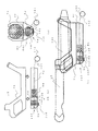
- FIG. 11 is a diagram showing a second embodiment of the vibration unit. This embodiment shows an example in which the mounting member and the vibration unit are integrally formed.
- 11 (a) is a top view of the vibration unit
- FIG. 11 (b) is a side view of the vibration member
- FIGS. 11 (c) and 11 (d) are a front view and a side view of the mounting member, respectively
- FIG. 11 (e) is a view showing a state where a vibration unit is attached to the ultrasonic probe 12.
- FIG. 11 (e) for the sake of convenience of explanation, members hidden inside the mounting member 72 are indicated by broken lines.
- the mounting member 72 is formed by extending a substantially U-shaped member in the vertical direction when viewed from above, and covers the outer periphery of the grip portion 12a of the ultrasonic probe 12. It comes to be installed.
- the guide rails 82 are formed on the inner surface of the mounting member 72 as a pair symmetrically with respect to the grip portion 12a along the axial direction of the ultrasonic probe 12.
- the vibration member 84 is formed by extending a substantially U-shaped member in the vertical direction when viewed from above, and on the inner peripheral side of the mounting member 72, the outer periphery of the grip portion 12a of the ultrasonic probe 12 It is provided so as to cover.
- a pair of sliding projections 84a are formed on the outer peripheral surface of the vibration member 84 at symmetrical positions with respect to the grip portion 12a of the ultrasonic probe 12, and the sliding projections 84a slide along the guide rail 82. It is provided to move.
- the compression spring 87 has one end fixed to the inner surface of the mounting member 72 and the other end fixed to the upper end of the vibration member 84. Although only one compression spring 87 is shown in FIG. 11 (e), in reality, a pair of compression springs 87 are provided with the gripping portion 12a of the ultrasonic probe 12 in between. As a result, both sides of the vibration member 84 sandwiching the grip portion 12a of the ultrasonic probe 12 are urged by the compression spring 87, so that the vibration member 84 is prevented from tilting and colliding with the stopper 80. Can do.
- the stopper 80 is formed so as to protrude from four locations on the inner surface of the mounting member 72 toward the center so as to be in contact with the lower end of the vibration member 84.
- the locking mechanism 90 of the present embodiment is disposed along the axial direction of the ultrasonic probe 12 on the opposite surface of the mounting member 72 that sandwiches the grip portion 12a of the ultrasonic probe 12.
- a pair of operation protrusions 84b are provided so as to stand up from the opposing surface sandwiching the portion 12a to the outer peripheral side.
- the operation protrusion 84b protrudes from the vertical slit 72a of the mounting member 72 and is slidable along a groove 84c formed in the lateral direction on the outer surface of the vibration member 84 as shown in FIG. Yes. That is, the operation protrusion 84b is formed to be slidable in the direction of the lateral slit 72b of the mounting member with respect to the vibration member 84. Further, a plurality (two in this embodiment) of the horizontal slits 72b are formed with respect to the long side of the vertical slit 72a of the mounting member 72.
- the operation protrusion 84b is slid along the vertical slit 72a of the mounting member 72, the vibration member 84 is slid to the set position of the guide rail 82, and the operation protrusion 84b is moved to either the upper or lower stage of the mounting member 72.
- the vibrating member 84 can be locked by sliding along the horizontal slit 72b and engaging with the horizontal slit 72b.
- the vibration member can be locked at a plurality of setting positions of the guide rail by forming the plurality of lateral slits 72b, measurement is performed according to the depth from the body surface of the subject at the diagnostic site, for example. When the part is relatively on the body surface of the subject, the driving distance of the vibration member 84 is shortened.
- FIG. 11 (e) shows a state in which the operation projection 84b is locked to the upper horizontal slit 72b.
- the lock release mechanism 92 of the present embodiment includes a pair of release arms 100 provided between the outer peripheral surface of the vibration member 84 and the inner peripheral surface of the mounting member 72.
- the release arm 102 is connected to both of the pair of release arms 100 and has a release protrusion 102 that protrudes from the mounting member 72.
- Each of the release arms 100 abuts against the surface on the opposite side of the longitudinal slit 72a of the pair of operating projections 84b of the vibration member 84, one end of which is locked to the lateral slit 72b of the mounting member 72, and in a direction along the lateral slit 72b. It is formed to extend.
- the release protrusion 102 can press both ends of the release arm 100 in a direction along the horizontal slit 72b, and is formed to protrude from the mounting member 72.
- the horizontal slit 72b is formed in two upper and lower stages, the release arm 100 is also provided in two upper and lower stages correspondingly.
- the examiner presses the release protrusions 102 protruding from the attachment member 72, thereby attaching the pair of operation protrusions 84b of the vibration member locked to the lateral slit 72b via the pair of release arms 100 to the attachment member.
- the vibration member 84 can be unlocked by sliding in the direction of the vertical slit 72a.
- the examiner can easily press the release protrusion 102 while imaging an ultrasonic tomographic image. Is preferable.
- both the pair of operation protrusions 84b of the vibration member 84 can be slid simultaneously by simply pressing one release protrusion 102.
- the lock can be released. Therefore, it is possible to easily release the lock as compared with the case where each of the pair of release arms is operated separately, and it is possible to avoid the vibration member from tilting and colliding with the stopper.
- the vibration unit corresponding to various types of general-purpose ultrasonic probes is required, while the vibration unit is downsized. Therefore, it is preferable because the ultrasonic probe can be easily handled at the time of diagnosis.
- the ultrasonic probe 12 when vibration is applied to the subject 10 using the excitation unit 14 as in the present embodiment, the ultrasonic probe 12 is tilted due to hand shake of the handle of the ultrasonic probe 12, etc. Although it is not preferable to deviate, since the handling of the ultrasonic probe is facilitated by downsizing the vibration unit, it is effective in preventing the displacement of the tomographic plane.
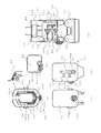
- FIG. 12 is a diagram showing a second embodiment of the vibration unit.
- the present embodiment shows an embodiment in which the ultrasonic probe 12 is a body cavity probe inserted into the body cavity of the subject 10.
- 12A is a side view of the mounting member and the vibration unit
- FIGS. 12B and 12C are a rear view and a side view of the state where the vibration unit is mounted on the ultrasonic probe.
- members hidden inside the vibration unit are indicated by broken lines for convenience of explanation.
- the mounting member 72 has a shape along the extending direction of the grip portion 12a of the ultrasonic probe 12, and is configured to be detachably mounted along the grip portion 12a.
- a cylindrical member 140 with one end closed extending along the extending direction of the mounting member 72 is detachably mounted below the mounting member 72.
- the cylindrical member 140 is detachably mounted on the lower surface of the mounting member 72 with the closed side positioned on the ultrasonic transmission / reception surface side of the ultrasonic probe 12.
- the guide rails 82 are formed on the inner surface of the cylindrical member 140 as a pair on the left and right along the cylinder axis.
- a pair of sliding protrusions 84 a corresponding to the guide rail 82 are formed on the left and right side surfaces of the vibration member 84 so as to be slidable along the guide rail 82.
- a tension spring 86 as an elastic member is provided with one end fixed to the front end of the cylindrical member 140 closing and the other end fixed to the front surface of the vibration member.
- the stopper 80 is provided in close contact with the tubular member 140 between both fixed ends of the tension spring 86.
- the vibration member operation string 142 has one end fixed to the rear surface of the vibration member 84, that is, the surface opposite to the surface to which the other end of the tension spring 86 is fixed, and the other end is opened after the cylindrical member 140 is opened. It is provided from the end. At the other end of the vibration member operation string 142, an operation member 143 that the examiner grips when the vibration member 84 is slid along the guide rail 82 is provided.
- the locking mechanism 90 of the present embodiment forms a part of the cylindrical wall of the cylindrical member 140, and the arm 144 extending along the cylindrical axis and the arm 144 in a seesaw shape.
- a support member (not shown) that supports the cylindrical member 140 so as to be able to bend and deform, and a locking projection 146 formed on the inner surface of the rear end portion of the arm 144 are configured.
- the locking protrusion 146 contacts the side surface of the vibration member 84 to bend and deform the arm 144, and pulls the vibration member operation string 142 so that the vibration member 84 When slid to the set position, the arm 144 is restored from the bending deformation and engaged with the end of the vibration member 84 to lock the vibration member 84.
- an unlocking portion 148 is formed on the outer surface of the front end portion of the arm 144.
- the unlocking portion 148 releases the engagement between the locking projection 146 of the arm 144 and the end portion of the vibration member 84 by pressing and deforming the arm 144 by pressing the outer surface of the front end portion of the arm 144. is there.
- the excitation unit of the present embodiment it is not necessary to use a dedicated probe for raising a shear wave on the subject even in the case of the intracavity probe inserted into the body cavity of the subject 10, and the subject It is possible to draw a shear wave image while confirming the ultrasonic tomographic image, and to measure elasticity information based on the propagation speed of the shear wave.
Landscapes
- Health & Medical Sciences (AREA)
- Engineering & Computer Science (AREA)
- Life Sciences & Earth Sciences (AREA)
- Physics & Mathematics (AREA)
- Pathology (AREA)
- Heart & Thoracic Surgery (AREA)
- Radar, Positioning & Navigation (AREA)
- General Physics & Mathematics (AREA)
- Biophysics (AREA)
- Nuclear Medicine, Radiotherapy & Molecular Imaging (AREA)
- Computer Networks & Wireless Communication (AREA)
- Radiology & Medical Imaging (AREA)
- Biomedical Technology (AREA)
- Remote Sensing (AREA)
- Medical Informatics (AREA)
- Molecular Biology (AREA)
- Surgery (AREA)
- Animal Behavior & Ethology (AREA)
- General Health & Medical Sciences (AREA)
- Public Health (AREA)
- Veterinary Medicine (AREA)
- Ultra Sonic Daignosis Equipment (AREA)
Abstract
Afin de mesurer des informations élastiques d'un corps à tester, sur la base d'une vitesse de propagation d'onde de partage, à l'aide d'une sonde ultrasonore universelle capable d'extraire une image tomographique ultrasonore et de supprimer l'effet d'un bruit d'onde électromagnétique sur des ondes ultrasonores, une unité d'excitation (14) comprend : un élément de montage (72) monté sur une sonde ultrasonore (12) de façon à être détachable ; un rail de guidage (82) s'étendant à partir de l'extrémité postérieure de l'élément de montage, un élément d'excitation (84) disposé le long du rail de guidage de façon à être coulissable, une butée (80) destinée à limiter le coulissement de l'élément d'excitation dans une direction (direction vers le bas), une paire de ressorts de tension (86) disposée de telle sorte que l'élément d'excitation coulisse dans une direction d'éloignement de la butée et stocke de l'énergie, un mécanisme de verrou destiné à verrouiller l'élément d'excitation dans une position dans laquelle l'élément d'excitation a stocké de l'énergie, et un mécanisme de libération de verrou destiné à libérer le verrou du mécanisme de verrou.
Priority Applications (1)
| Application Number | Priority Date | Filing Date | Title |
|---|---|---|---|
| JP2011518447A JP5552120B2 (ja) | 2009-06-11 | 2010-06-01 | 加振ユニット、超音波探触子、及び超音波診断装置 |
Applications Claiming Priority (2)
| Application Number | Priority Date | Filing Date | Title |
|---|---|---|---|
| JP2009139791 | 2009-06-11 | ||
| JP2009-139791 | 2009-06-11 |
Publications (1)
| Publication Number | Publication Date |
|---|---|
| WO2010143555A1 true WO2010143555A1 (fr) | 2010-12-16 |
Family
ID=43308810
Family Applications (1)
| Application Number | Title | Priority Date | Filing Date |
|---|---|---|---|
| PCT/JP2010/059241 Ceased WO2010143555A1 (fr) | 2009-06-11 | 2010-06-01 | Unité d'excitation, sonde ultrasonore et équipement de diagnostic à ultrasons |
Country Status (2)
| Country | Link |
|---|---|
| JP (1) | JP5552120B2 (fr) |
| WO (1) | WO2010143555A1 (fr) |
Cited By (5)
| Publication number | Priority date | Publication date | Assignee | Title |
|---|---|---|---|---|
| JP2015039583A (ja) * | 2013-08-23 | 2015-03-02 | ジーイー・メディカル・システムズ・グローバル・テクノロジー・カンパニー・エルエルシー | アタッチメント、超音波プローブ及び超音波診断装置 |
| JP2019513502A (ja) * | 2016-08-04 | 2019-05-30 | 无錫海斯凱尓医学技術有限公司Wuxi Hisky Medical Technologies Co.,Ltd. | 超音波装置及び機械的振動発生装置 |
| CN110207869A (zh) * | 2019-05-17 | 2019-09-06 | 杭州戬威机电科技有限公司 | 一种应力检测探头夹具 |
| CN115551415A (zh) * | 2020-05-11 | 2022-12-30 | 皇家飞利浦有限公司 | 用于超声弹性成像的机械剪切波生成 |
| WO2023246721A1 (fr) * | 2022-06-20 | 2023-12-28 | 深圳市影越医疗科技有限公司 | Appareil, procédé et système de mesure d'élasticité |
Citations (6)
| Publication number | Priority date | Publication date | Assignee | Title |
|---|---|---|---|---|
| JP2004261198A (ja) * | 2003-01-15 | 2004-09-24 | Hitachi Medical Corp | 超音波診断装置 |
| JP2005144155A (ja) * | 2003-10-20 | 2005-06-09 | National Institute Of Advanced Industrial & Technology | 超音波を利用した軟組織の粘弾性推定装置およびプログラム |
| JP2005534455A (ja) * | 2002-08-08 | 2005-11-17 | エコセンス | 人間または動物の器官の弾性測定装置および方法 |
| JP2007044231A (ja) * | 2005-08-10 | 2007-02-22 | Hitachi Medical Corp | 超音波診断装置 |
| WO2007100107A1 (fr) * | 2006-03-02 | 2007-09-07 | Hitachi Medical Corporation | Dispositif de compression automatique et echographe utilisant celui-ci |
| JP2008000588A (ja) * | 2006-05-25 | 2008-01-10 | Hitachi Medical Corp | 超音波診断装置 |
Family Cites Families (4)
| Publication number | Priority date | Publication date | Assignee | Title |
|---|---|---|---|---|
| JPS643604U (fr) * | 1987-06-29 | 1989-01-11 | ||
| JP3004906U (ja) * | 1994-06-02 | 1994-12-06 | マルゴ味噌株式会社 | 骨粗鬆症診断装置の骨伝導波検出器 |
| JPH08294492A (ja) * | 1995-04-26 | 1996-11-12 | A & D Co Ltd | 加振台 |
| JP4021836B2 (ja) * | 2003-01-17 | 2007-12-12 | アロカ株式会社 | 超音波診断システム及び超音波探触子保持装置 |
-
2010
- 2010-06-01 WO PCT/JP2010/059241 patent/WO2010143555A1/fr not_active Ceased
- 2010-06-01 JP JP2011518447A patent/JP5552120B2/ja not_active Expired - Fee Related
Patent Citations (6)
| Publication number | Priority date | Publication date | Assignee | Title |
|---|---|---|---|---|
| JP2005534455A (ja) * | 2002-08-08 | 2005-11-17 | エコセンス | 人間または動物の器官の弾性測定装置および方法 |
| JP2004261198A (ja) * | 2003-01-15 | 2004-09-24 | Hitachi Medical Corp | 超音波診断装置 |
| JP2005144155A (ja) * | 2003-10-20 | 2005-06-09 | National Institute Of Advanced Industrial & Technology | 超音波を利用した軟組織の粘弾性推定装置およびプログラム |
| JP2007044231A (ja) * | 2005-08-10 | 2007-02-22 | Hitachi Medical Corp | 超音波診断装置 |
| WO2007100107A1 (fr) * | 2006-03-02 | 2007-09-07 | Hitachi Medical Corporation | Dispositif de compression automatique et echographe utilisant celui-ci |
| JP2008000588A (ja) * | 2006-05-25 | 2008-01-10 | Hitachi Medical Corp | 超音波診断装置 |
Cited By (8)
| Publication number | Priority date | Publication date | Assignee | Title |
|---|---|---|---|---|
| JP2015039583A (ja) * | 2013-08-23 | 2015-03-02 | ジーイー・メディカル・システムズ・グローバル・テクノロジー・カンパニー・エルエルシー | アタッチメント、超音波プローブ及び超音波診断装置 |
| JP2019513502A (ja) * | 2016-08-04 | 2019-05-30 | 无錫海斯凱尓医学技術有限公司Wuxi Hisky Medical Technologies Co.,Ltd. | 超音波装置及び機械的振動発生装置 |
| US11090028B2 (en) | 2016-08-04 | 2021-08-17 | Wuxi Hisky Medical Technologies Co., Ltd. | Ultrasonic device and device for generating mechanical vibration |
| CN110207869A (zh) * | 2019-05-17 | 2019-09-06 | 杭州戬威机电科技有限公司 | 一种应力检测探头夹具 |
| CN115551415A (zh) * | 2020-05-11 | 2022-12-30 | 皇家飞利浦有限公司 | 用于超声弹性成像的机械剪切波生成 |
| US20230181162A1 (en) * | 2020-05-11 | 2023-06-15 | Koninklijke Philips N.V. | Mechanical shear wave generation for ultrasonic elastography |
| US12364463B2 (en) * | 2020-05-11 | 2025-07-22 | Koninklijke Philips N.V. | Mechanical shear wave generation for ultrasonic elastography |
| WO2023246721A1 (fr) * | 2022-06-20 | 2023-12-28 | 深圳市影越医疗科技有限公司 | Appareil, procédé et système de mesure d'élasticité |
Also Published As
| Publication number | Publication date |
|---|---|
| JPWO2010143555A1 (ja) | 2012-11-22 |
| JP5552120B2 (ja) | 2014-07-16 |
Similar Documents
| Publication | Publication Date | Title |
|---|---|---|
| CN102469989B (zh) | 超声波诊断装置和超声波测量方法 | |
| JP4898809B2 (ja) | 超音波診断装置 | |
| JP4465535B2 (ja) | 弾性画像表示方法及び超音波診断装置 | |
| JP4455003B2 (ja) | 超音波診断装置 | |
| JP5371199B2 (ja) | 超音波診断装置 | |
| US20120209115A1 (en) | Ultrasonic diagnostic device, method for generating image for evaluating disorder of part to be diagnosed of object, and program for generating image for evaluating disorder of part to be diagnosed of object | |
| JPH05317313A (ja) | 超音波診断装置 | |
| JP5552120B2 (ja) | 加振ユニット、超音波探触子、及び超音波診断装置 | |
| JP2005066041A5 (fr) | ||
| WO2009104657A1 (fr) | Dispositif ultrasonographique, procédé de traitement d'image par ultrasons et programme de traitement d'image par ultrasons | |
| JP5249327B2 (ja) | 超音波診断装置 | |
| KR101666324B1 (ko) | 초음파 진단 장치 | |
| CN108697406A (zh) | 超声波诊断装置以及超声波信息处理方法 | |
| JP2012249776A (ja) | 超音波診断装置 | |
| WO2011001776A1 (fr) | Appareil de diagnostic ultrasonore et procédé de génération d'image par propagation d'ondes rotationnelles | |
| JP2016002208A (ja) | 超音波診断装置 | |
| JP5473527B2 (ja) | 超音波診断装置 | |
| JP2007044231A (ja) | 超音波診断装置 | |
| JP2011072522A (ja) | 超音波診断装置及び方法 | |
| JP5455592B2 (ja) | 超音波診断装置、及び超音波画像表示方法 | |
| JP4889540B2 (ja) | 超音波診断装置 | |
| JP5789599B2 (ja) | 超音波診断装置 | |
| JP6144990B2 (ja) | 超音波画像撮像装置及び超音波画像撮像方法 | |
| JP2013240721A (ja) | 超音波診断装置 | |
| JPWO2011096556A1 (ja) | 超音波診断装置、及び血流画像生成方法 |
Legal Events
| Date | Code | Title | Description |
|---|---|---|---|
| 121 | Ep: the epo has been informed by wipo that ep was designated in this application |
Ref document number: 10786086 Country of ref document: EP Kind code of ref document: A1 |
|
| NENP | Non-entry into the national phase |
Ref country code: DE |
|
| WWE | Wipo information: entry into national phase |
Ref document number: 2011518447 Country of ref document: JP |
|
| 122 | Ep: pct application non-entry in european phase |
Ref document number: 10786086 Country of ref document: EP Kind code of ref document: A1 |