WO2010143580A1 - Dessous de verre à diodes électroluminescentes - Google Patents
Dessous de verre à diodes électroluminescentes Download PDFInfo
- Publication number
- WO2010143580A1 WO2010143580A1 PCT/JP2010/059444 JP2010059444W WO2010143580A1 WO 2010143580 A1 WO2010143580 A1 WO 2010143580A1 JP 2010059444 W JP2010059444 W JP 2010059444W WO 2010143580 A1 WO2010143580 A1 WO 2010143580A1
- Authority
- WO
- WIPO (PCT)
- Prior art keywords
- led
- switch
- cover
- coaster
- led coaster
- Prior art date
- Legal status (The legal status is an assumption and is not a legal conclusion. Google has not performed a legal analysis and makes no representation as to the accuracy of the status listed.)
- Ceased
Links
Images


Classifications
-
- A—HUMAN NECESSITIES
- A47—FURNITURE; DOMESTIC ARTICLES OR APPLIANCES; COFFEE MILLS; SPICE MILLS; SUCTION CLEANERS IN GENERAL
- A47G—HOUSEHOLD OR TABLE EQUIPMENT
- A47G23/00—Other table equipment
- A47G23/03—Underlays for glasses or drinking-vessels
- A47G23/0306—Underlays for glasses or drinking-vessels with means for amusing or giving information to the user
- A47G23/0309—Illuminated
-
- F—MECHANICAL ENGINEERING; LIGHTING; HEATING; WEAPONS; BLASTING
- F21—LIGHTING
- F21V—FUNCTIONAL FEATURES OR DETAILS OF LIGHTING DEVICES OR SYSTEMS THEREOF; STRUCTURAL COMBINATIONS OF LIGHTING DEVICES WITH OTHER ARTICLES, NOT OTHERWISE PROVIDED FOR
- F21V33/00—Structural combinations of lighting devices with other articles, not otherwise provided for
- F21V33/0004—Personal or domestic articles
- F21V33/0024—Household or table equipment
- F21V33/0036—Table-ware or table equipment, e.g. dishes, cutlery or trays
-
- F—MECHANICAL ENGINEERING; LIGHTING; HEATING; WEAPONS; BLASTING
- F21—LIGHTING
- F21Y—INDEXING SCHEME ASSOCIATED WITH SUBCLASSES F21K, F21L, F21S and F21V, RELATING TO THE FORM OR THE KIND OF THE LIGHT SOURCES OR OF THE COLOUR OF THE LIGHT EMITTED
- F21Y2115/00—Light-generating elements of semiconductor light sources
- F21Y2115/10—Light-emitting diodes [LED]
Definitions
- the present invention relates to a coaster that receives a glass such as a glass containing drinks such as liquor and soft drinks, and more particularly to an LED coaster that can be illuminated from the bottom of the cup in order to improve the atmosphere when eating and drinking.
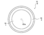
- FIGS. 9 is a top view of a conventional LED coaster 110
- FIG. 10 is a bottom view of the conventional LED coaster 110
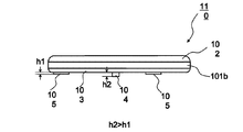
- FIG. 11 is a side view of the conventional LED coaster 110
- FIG. 12 is a view of the conventional LED coaster 110 placed on a table or the like.
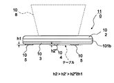
- FIG. 13 is a side view showing a state in which a conventional LED coaster 110 is placed on a table or the like and a cup containing a beverage is placed thereon.
- the conventional LED coaster 110 has a circular translucent cover 101 on the upper surface (the surface on which the cup is placed), and an upper surface circumferential cover 102 that covers the outer periphery of the upper surface of the translucent cover 101 is provided.
- the translucent cover 101 is not transparent as a whole, and a transparent translucent portion 101a is formed at a substantially central portion of the upper surface, and a transparent translucent portion 101b is formed on a side surface. The light from the LED (light emitting diode) is transmitted to the outside from the light transmitting portions 101a and 101b.
- the LED is disposed inside (on the back side) facing the translucent part 101a. Therefore, the LED is located at a substantially central portion of the LED coaster 110.
- the LED is mounted on a substrate (not shown).
- the bottom surface of the LED coaster 110 is composed of a circular bottom surface cover 103. Near the outer periphery of the bottom cover 103, three rubber pads 105 are provided at substantially equal intervals. The rubber pad 105 is a part that comes into contact with the table or the like when the LED coaster 110 is placed on the table or the like.
- a switch pad 104 for turning on the LED is provided at a position slightly away from the center of the bottom cover 103. As described above, since the LED is located at a substantially central portion of the LED coaster 110, the switch pad 104 is located slightly away from the central portion of the LED coaster 110 due to the layout of the board.
- an elongated battery cover 106 is fastened with a screw 107 at a predetermined position of the bottom cover 103.
- Two button batteries are accommodated in the inside (back side) facing the battery cover 106.
- the button battery is a power source for the LED.
- the switch pad 104 is attached to the bottom cover 103 so as to be movable in the vertical direction (the thickness direction of the LED coaster 110).
- the ridge of the switch pad 104 is placed on the stepped portion (not shown) of the circular hole of the bottom cover 103. Placed. In this state, there is a gap (play) between the switch on the board and the switch pad 104.
- the height h1 protruding from the bottom cover 103 of the rubber pad 105 and the switch pad 104 are shown in FIG.
- the height h2 protruding from the bottom cover 103 satisfies the relationship h2> h1.
- the weight of the LED coaster 110 is added to the switch pad 104 as shown in FIG.
- the switch pad 104 enters the inside of the LED coaster 110 by the gap (play) between them, and the switch pad 104 contacts the switch on the board.
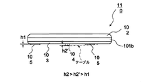
- the LED coaster 110 is placed on a table or the like with two rubber pads 105 and a switch pad 104 on the button battery side contacting the table or the like. If the height of the switch pad 104 protruding from the bottom cover 103 at this time is h2 ′, the relationship of h2> h2 ′> h1 is satisfied.
- the switch does not operate if the switch pad 104 just contacts the switch on the board. When the switch pad 104 presses the switch on the substrate, the switch operates and the LED is lit.
- the switch pad 104 is moved to the cup 108 or the like.
- the switch enters the LED coaster 110 due to the weight of the switch and presses the switch on the board, the switch operates and the LED lights up.
- the switch pad 104 on the side opposite to the button battery is floating from the table. Therefore, the LED coaster 110 is in an unstable state, and some people who use the LED coaster 110 may be frustrated.
- the LED coaster 110 is stable.
- a mounting table having a mounting surface on which a cup is placed on the upper surface is supported by a coil spring so that it can be moved up and down in order to eliminate the hassle of turning a switch on and off by a person.
- a printed circuit board is fixed to the upper surface of the support base, and an LED and a push switch are attached on the printed circuit board.
- the present invention has been made to solve the above-described problems.
- an LED coaster When an LED coaster is placed on a table and a glass or the like containing a beverage is placed on the LED coaster, the LED is stable and does not rattle. Provide a coaster.
- An LED coaster is provided between a translucent cover on which an article is placed, a bottom cover attached to the lower surface of the translucent cover, and the translucent cover and the bottom cover.
- the LED is mounted on the component side on the cover side, and the board on which the switch for turning on / off the LED is mounted on the solder surface on the bottom cover side, and the battery storage portion of the bottom cover, are supplied with power.
- the rubber pad and the switch pad are arranged at substantially equal intervals in the circumferential direction near the outer periphery of the bottom surface of the bottom cover, and the diameter of the switch pad is set to the LED coaster. And said that with half a little less than a diameter of the.
- the LED coaster according to the present invention is characterized in that the LED mounted on the substrate is located at a substantially central portion of the LED coaster.
- the LED coaster according to the present invention is characterized in that the light-transmitting cover includes a light-transmitting portion that transmits light from the LED at a substantially central portion and a side portion of the light-transmitting cover.
- the LED coaster according to the present invention is characterized in that the switch pressing portion of the switch pad is disposed at a substantially central portion of the switch pad.
- the LED coaster according to the present invention is characterized in that the switch pressing portion has a cross shape.
- the dimension that projects outward from the bottom surface of the bottom cover of the switch pad is d1
- the dimension that projects outward from the bottom surface of the bottom cover of the rubber pad is d2.
- the LED coaster according to the present invention is characterized in that two rubber pads are arranged at an interval of approximately 120 ° with the battery storage portion of the bottom cover interposed therebetween.
- the battery storage portion of the bottom cover is formed by a concave portion having a convex shape inside the bottom cover, and after storing the battery in the battery storage portion, the battery storage portion is closed by the battery cover. It is characterized by.
- the switch pad is movable in the thickness direction of the LED coaster by guiding the holes of the protruding portion of the switch pad to the plurality of pins standing on the back surface of the bottom cover.
- the two rubber pads and the switch pad are arranged in the vicinity of the outer periphery of the bottom surface of the bottom cover at substantially equal intervals in the circumferential direction, and the diameter of the switch pad is set to 1 / diameter of the LED coaster. Since the LED coaster is placed on a table and a glass containing a drink is placed on the LED coaster, an LED coaster that is stable and free from rattling can be provided.
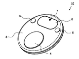
- FIG. 3 shows the first embodiment and is a top view of the LED coaster 10.
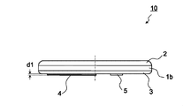
- FIG. 3 shows the first embodiment, and is a side view of the LED coaster 1.
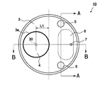
- FIG. 3 is a diagram showing the first embodiment and is a bottom view of the LED coaster 10.
- FIG. 5 is a diagram showing the first embodiment, and is a perspective view of the LED coaster 10 as seen from the bottom surface side.
- FIG. 4 shows the first embodiment, and is a cross-sectional view taken along the line AA in FIG.
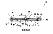
- FIG. 5 shows the first embodiment, and is a cross-sectional view taken along the line BB of FIG.
- FIG. 4 is a diagram showing the first embodiment, and is a plan view of the inside of the LED coaster 10 with the translucent cover 1 removed.
- FIG 3 is a diagram showing the first embodiment, and is a perspective view of the inside of the LED coaster 10 with the translucent cover 1 removed.
- FIG. The side view of the conventional LED coaster 110.
- FIG. 1 to FIG. 8 are diagrams showing Embodiment 1, FIG. 1 is a top view of an LED coaster 10, FIG. 2 is a side view of the LED coaster 10, FIG. 3 is a bottom view of the LED coaster 10, and FIG. 5 is a cross-sectional view taken along the line AA in FIG. 3, FIG. 6 is a cross-sectional view taken along the line BB in FIG. 3, and FIG. 7 is an internal view of the LED coaster 10 with the translucent cover 1 removed.
- FIG. 8 is a perspective view of the inside of the LED coaster 10 with the translucent cover 1 removed.
- the upper surface (upper part) of the LED coaster 10 is the same as the conventional LED coaster 110. That is, the LED coaster 10 has a transparent plastic cover 1 made of plastic on the upper surface (the surface on which an article such as a cup is placed), and an upper peripheral cover 2 that covers the outer peripheral portion of the upper surface of the transparent cover 1 is provided. ing.
- the translucent cover 1 is not transparent as a whole, and has a transparent light transmitting portion 1a at a substantially central portion of the upper surface and a transparent light transmitting portion 1b (see FIG. 2) on the side surface. It is the structure which the light of LED (light emitting diode) permeate
- the bottom surface of the LED coaster 10 is composed of a circular bottom cover 3.
- Two rubber pads 5 and one switch pad 4 having a large diameter are provided near the outer periphery of the bottom surface of the bottom cover 3 (see FIG. 3).
- the LED coaster 10 of the present embodiment is different from the conventional LED coaster 110 in the following points.
- the conventional LED coaster 110 uses three rubber pads 105
- the LED coaster 10 of the present embodiment uses two rubber pads 5.
- the two rubber pads 5 on the battery cover 6 side are provided in the same manner as the two conventional rubber pads 105.
- the conventional LED coaster 110 uses one rubber pad 105, but the LED coaster 10 of the present embodiment uses a switch pad instead of the rubber pad 5. 4 is used.
- the circular switch pad 4 is not smaller in diameter than the conventional switch pad 104, and is larger in diameter than the conventional switch pad 104. In one example, when the LED coaster 10 has a diameter of about 90 mm, the switch pad 4 has a diameter of about 40 mm. The diameter of the conventional switch pad 104 is about 7 mm.
- the two rubber pads 5 are arranged at an interval of approximately 120 ° with the battery cover 6 on the bottom surface of the bottom cover 3 interposed therebetween.
- One switch pad 4 having a large diameter is located approximately in the middle of the two rubber pads 5 (approximately 120 ° in angle) inside the hole 3e of the bottom cover 3 near the outer periphery of the bottom cover 3 opposite to the battery cover 6. ) Position.
- the LED coaster 10 When the LED coaster 10 is placed on a table or the like, it is supported on the table or the like at three points: two rubber pads 5 provided near the outer periphery of the bottom surface of the bottom cover 3 and one switch pad 4 having a large diameter. The stability of the LED coaster 10 is good and there is no rattling.
- the conventional LED coaster 110 is also supported by the table or the like at three points of the two rubber pads 105 and the switch pad 104 when the LED coaster 110 is in a normal posture (state) and the LED coaster 110 is placed on the table or the like. However, since the switch pad 104 is near the center of the LED coaster 110, the stability was lacking.
- the battery cover 6 having a long hole shape is attached to a boss portion 3 b (see FIG. 6) provided in the battery housing portion 3 a (see FIGS. 6 to 8) of the bottom surface cover 3 with screws 7. Fixed.
- the battery storage portion 3 a of the bottom cover 3 is formed with a concave portion having a convex shape inside the bottom cover 3.
- the switch pad 4 protrudes outward from the bottom surface of the bottom cover 3 by a dimension d1.
- d1 is about 1.3 mm.
- the rubber pad 5 protrudes outward from the bottom surface of the bottom cover 3 by a dimension d2.
- d2 is about 1.0 mm.
- the LED 20 is mounted on the component surface of the rectangular substrate 40.
- the substrate 40 is a single-sided substrate, and one surface is a component surface and the other surface is a solder surface.
- the substrate 40 is attached to the boss 3c (FIG. 6) of the bottom cover 3 with the screw 9 (so that the component surface of the substrate 40 is on the translucent cover 1 side and the solder surface of the substrate 40 is on the bottom cover 3 side. 6).
- the layout of the substrate 40 and the positional relationship between the substrate 40 and the bottom cover 3 are determined so that the LED 20 is positioned at substantially the center of the LED coaster 10.
- a switch 30 for turning on / off the LED 20 is mounted.
- the switch 30 is disposed to face a switch pressing portion 4a (FIG. 6) provided at a substantially central portion of the switch pad 4.
- the entire switch pad 4 is substantially circular and has a resin dish shape.
- the dish is convex outward.
- the bottom surface of the dish is a circular mounting surface 4c when the switch pad 4 is placed on a table or the like.
- a side wall is erected from the outer peripheral edge of the circular mounting surface 4c, and an annular flange portion 4b is formed on the outer side substantially parallel to the mounting surface 4c from the inner end of the side wall.
- substantially semicircular projecting portions 4d projecting outward are formed at substantially equal intervals (90 °) in the circumferential direction.
- circular holes are formed in the four projecting portions 4d.
- a pin 3d is erected on the back surface of the bottom cover 3 so as to correspond to the circular holes of the four protruding portions 4d of the switch pad 4.
- the circular holes of the four protrusions 4d of the switch pad 4 are fitted into the pins 3d with a predetermined gap. Accordingly, the switch pad 4 is positioned by the pin 3d of the bottom cover 3 and is movable in the thickness (up and down) direction of the LED coaster 10.
- a switch pressing portion 4a (FIG. 6) for pressing the switch 30 of the substrate 40 is formed at a substantially central portion of the back surface of the switch pad 4 (inside of the LED coaster 10).
- the shape of the switch pressing portion 4a is, for example, a cross.
- the shape of the switch pressing portion 4a is not limited to a cross, and may be any shape.
- the battery cover 6 is provided with a pair of battery terminals (not shown, independent of each other) provided on the battery cover 3a of the bottom cover 3 on the side opposite to the battery cover 6. 12 is attached.
- the battery terminal 12 also has a pair of terminals, which are connected (electrically conductive) to each other.
- a pair of battery terminals (not shown, independent of each other) provided on the battery cover 3a of the bottom cover 3 on the opposite side of the battery cover 6 and the battery terminals 12 of the battery cover 6 both use leaf springs. ing.
- the electrical path between the substrate 40 and the button battery 60 is, for example, one lead wire 50 drawn from the substrate 40 ⁇ on the side opposite to the battery cover 6 of the battery housing portion 3a of the bottom cover 3.
- the other of the pair of battery terminals provided on the side opposite to the battery cover 6 of the battery housing 3 a of the bottom cover 3 ⁇ the other lead wire 50 drawn from the substrate 40.
- the switch pad 4 will be described in more detail. For example, when the LED coaster 10 has a diameter of about 90 mm, the switch pad 4 has a diameter of about 40 mm. The diameter of the switch pad 4 is about a half of the diameter of the LED coaster 10.
- the switch pad 4 and the two rubber pads 5 are arranged at substantially equal intervals in the circumferential direction near the outer periphery of the bottom surface of the bottom cover 3.
- the two rubber pads 5 are fixed to the bottom surface of the bottom cover 3, but the switch pad 4 is provided with four protrusions of the switch pad 4 on the four pins 3 d erected on the back surface of the bottom cover 3.
- the 4d circular hole is guided and is movable in the thickness (up and down) direction of the LED coaster 10.
- the switch pressing portion 4 a (FIG. 6) that presses the switch 30 of the switch pad 4 is provided at a substantially central portion of the switch pad 4.
- the LED coaster 10 When the LED coaster 10 is placed on a table or the like, and a glass or the like containing a beverage is placed on the LED coaster 10, the weight of the glass is dispersed on the switch pad 4 and the two rubber pads 5 and is distributed on the table or the like. Supported.
- the distance L1 (FIGS. 3 and 6) from the center of the LED coaster 10 of the switch pressing portion 4a of the switch pad 4 is about 19 mm in one example when the diameter of the LED coaster 10 is about 90 mm.
- the distance from the center of the LED coaster 10 between the two rubber pads 5 is about 36 mm in one example when the diameter of the LED coaster 10 is about 90 mm.
- the distance between the two rubber pads 5 is about 62 mm.
- the weight of the glass is distributed to the switch pad 4 and the two rubber pads 5 and supported by a table or the like.
- the weight of the glass is added to the pad 4, and the switch pressing portion 4 a of the switch pad 4 presses the switch 30 to light the LED 20.
- the switch pad 4 has a diameter of about 40 mm, but the switch pad 4 has a smaller diameter, for example, the same as the diameter of the conventional switch pad 104 (7 mm
- the switch pad 4 is arranged near the outer periphery of the bottom surface of the bottom cover 3.
- the weight of glass or the like is added to the switch pad 4 and the two rubber pads 5 in a substantially uniform manner. As a result, the weight applied to the switch pad 4 is reduced compared to when the diameter of the switch pad 4 is about 40 mm, and the switch 30 may not operate.
- the diameter of the switch pad 4 is about 40 mm, but the diameter of the switch pad 4 is made smaller than this, for example, the same as the diameter of the conventional switch pad 104 (about 7 mm), and the switch pad 4 is made to be the bottom cover 3.
- positions near the center of the bottom face of is assumed.
- the weight of the glass or the like is mainly applied to the switch pad 4 and the switch 30 operates.
- the glass or the like is placed on the LED coaster 10 by shifting to the opposite side of the two rubber pads 5, Since there is nothing that supports the LED coaster 10 on the side opposite to the individual rubber pads 5, there is a risk that the glass or the like may be inclined.
- the position of the switch pad 4 is preferably near the outer periphery of the bottom surface of the bottom cover 3, and the switch pad 4 is positioned so that the position of the switch pressing portion 4 a of the switch pad 4 is near the center of the bottom surface of the bottom cover 3. It is preferable to make the diameter of this as large as possible.
- the LED coaster 10 has a circular outer shape, but the outer shape is not limited to a circular shape. It may be of any shape.
- the LED coaster 10 is supported by the table or the like at the three points of the switch pad 4 and the two rubber pads 5 arranged near the outer periphery of the bottom surface of the bottom cover 3, and the switch pressing portion 4a.
- the diameter of the switch pad 4 having a substantially central portion is set to be slightly less than half of the diameter of the LED coaster 10, so that when the glass or the like containing the drink is placed on the LED coaster 10,
- the switch coasting unit 4a can press the switch 30 to turn on the switch 30, and the LED coaster 10 can be placed with a glass or the like containing a beverage without the LED coaster 10 rattling.
Landscapes
- Engineering & Computer Science (AREA)
- General Engineering & Computer Science (AREA)
- Table Equipment (AREA)
- Arrangement Of Elements, Cooling, Sealing, Or The Like Of Lighting Devices (AREA)
Abstract
L'invention porte sur un dessous de verre à diodes électroluminescentes, lequel dessous de verre est configuré de telle manière que, lorsque le dessous de verre à diodes électroluminescentes est disposé sur une table et qu'une tasse ou analogue, qui contient une boisson, est disposée sur le dessous de verre à diodes électroluminescentes, le dessous de verre à diodes électroluminescentes est stable sur la table et n'oscille pas. Un dessous de verre à diodes électroluminescentes comprend : un revêtement transmettant la lumière ayant une surface supérieure sur laquelle est placé un article ; un revêtement de surface inférieure monté sur la surface inférieure du revêtement transmettant la lumière ; une carte de circuits imprimés ayant une diode électroluminescente montée sur celle-ci, et ayant également, montée sur celle-ci, un commutateur pour allumer/éteindre la diode électroluminescente ; une pile ou batterie contenue dans une section de disposition de pile au niveau du revêtement de surface inférieure, et délivrant l'énergie électrique à la diode électroluminescente ; deux tampons en caoutchouc montés sur la surface inférieure du revêtement de surface inférieure ; et un tampon de commutateur monté sur l'intérieur du revêtement de surface inférieure de façon à être mobile dans la direction de haut en bas, et ayant une section de pression de commutateur qui est disposée de façon à faire face au commutateur. Les deux tampons en caoutchouc et le tampon de commutateur sont disposés de façon à être espacés de façon sensiblement égale dans la direction circonférentielle au voisinage de la périphérie externe de la surface inférieure du revêtement de surface inférieure. Le diamètre du tampon de commutateur est établi de façon à être légèrement inférieur à la moitié du diamètre du dessous de verre à diodes électroluminescentes.
Priority Applications (3)
| Application Number | Priority Date | Filing Date | Title |
|---|---|---|---|
| EP10786111A EP2441357A4 (fr) | 2009-06-12 | 2010-06-03 | Dessous de verre à diodes électroluminescentes |
| US13/375,788 US20120075844A1 (en) | 2009-06-12 | 2010-06-03 | Led coaster |
| CN2010800254224A CN102802471A (zh) | 2009-06-12 | 2010-06-03 | Led杯垫 |
Applications Claiming Priority (2)
| Application Number | Priority Date | Filing Date | Title |
|---|---|---|---|
| JP2009140651A JP5473418B2 (ja) | 2009-06-12 | 2009-06-12 | Ledコースター |
| JP2009-140651 | 2009-06-12 |
Publications (1)
| Publication Number | Publication Date |
|---|---|
| WO2010143580A1 true WO2010143580A1 (fr) | 2010-12-16 |
Family
ID=43308835
Family Applications (1)
| Application Number | Title | Priority Date | Filing Date |
|---|---|---|---|
| PCT/JP2010/059444 Ceased WO2010143580A1 (fr) | 2009-06-12 | 2010-06-03 | Dessous de verre à diodes électroluminescentes |
Country Status (5)
| Country | Link |
|---|---|
| US (1) | US20120075844A1 (fr) |
| EP (1) | EP2441357A4 (fr) |
| JP (1) | JP5473418B2 (fr) |
| CN (1) | CN102802471A (fr) |
| WO (1) | WO2010143580A1 (fr) |
Families Citing this family (7)
| Publication number | Priority date | Publication date | Assignee | Title |
|---|---|---|---|---|
| US9289042B2 (en) | 2012-07-23 | 2016-03-22 | Make-Cup, L.L.C. | Cosmetics container |
| CN104507203B (zh) * | 2014-11-21 | 2017-01-18 | 宁波市柯玛士太阳能科技有限公司 | 一种发光杯垫的控制电路及其杯垫 |
| TWM534570U (zh) * | 2016-07-12 | 2017-01-01 | San Ho Enterprise Co Ltd | 發光座 |
| US20180094804A1 (en) * | 2016-09-30 | 2018-04-05 | Danny Brannagan | Pumpkin Display Stand |
| CN108402855A (zh) * | 2018-04-09 | 2018-08-17 | 东莞市华卡达实业有限公司 | 一种led发光杯垫 |
| US12117156B2 (en) | 2022-05-27 | 2024-10-15 | Make It Better Llc | Attachable battery-powered light assembly for illuminating a bottle and method for illuminating a bottle with a light assembly |
| WO2025255301A1 (fr) * | 2024-06-05 | 2025-12-11 | Washaroo Corp. | Porte-savon à bande lumineuse intégrée |
Citations (4)
| Publication number | Priority date | Publication date | Assignee | Title |
|---|---|---|---|---|
| CN2607919Y (zh) * | 2003-03-14 | 2004-03-31 | 毛启伦 | 一种杯垫 |
| CN2609452Y (zh) * | 2003-03-24 | 2004-04-07 | 张美宁 | 闪光杯垫 |
| JP2004105337A (ja) * | 2002-09-17 | 2004-04-08 | Maruka Kinzoku Kk | コースタ |
| JP2006020926A (ja) | 2004-07-09 | 2006-01-26 | Narita Giken Kk | 照明付きコースター |
Family Cites Families (11)
| Publication number | Priority date | Publication date | Assignee | Title |
|---|---|---|---|---|
| JPH0518366U (ja) * | 1991-08-29 | 1993-03-09 | 幸治 川口 | 載置台 |
| JPH0531673U (ja) * | 1991-10-09 | 1993-04-27 | 三共精工株式会社 | グラス等の物品用下敷体 |
| US5785407A (en) * | 1996-11-18 | 1998-07-28 | Marpole International Inc. | Illuminable container |
| US6109583A (en) * | 1998-05-26 | 2000-08-29 | Nunes; Brendon G. | Tabletop having transparent surface and non scratch feet |
| US6164793A (en) * | 1999-11-30 | 2000-12-26 | Wu; Hui-Ming | Refractive coaster |
| DE20204026U1 (de) * | 2002-03-13 | 2003-01-16 | Dörfler, Barbara, 69115 Heidelberg | Glas- und Flaschenuntersetzer, welcher nach dem Aufsetzen eines Glases/einer Flasche diese von unten beleuchtet |
| US6793363B2 (en) * | 2002-12-13 | 2004-09-21 | Christopher A. Jensen | Illuminated coaster |
| US20050013129A1 (en) * | 2003-07-18 | 2005-01-20 | Mei-Ning Zhang | Cup pad with a radiation means |
| CN2817650Y (zh) * | 2004-10-27 | 2006-09-20 | 恩雨彩虹贸易有限公司 | 闪光声控杯垫 |
| US7690533B2 (en) * | 2005-12-13 | 2010-04-06 | Soap Labs, LLC | Lighted product dispenser |
| US7926966B2 (en) * | 2008-11-14 | 2011-04-19 | We Glowsource, Inc. | Illuminable device for accessorizing a vessel |
-
2009
- 2009-06-12 JP JP2009140651A patent/JP5473418B2/ja not_active Expired - Fee Related
-
2010
- 2010-06-03 CN CN2010800254224A patent/CN102802471A/zh active Pending
- 2010-06-03 US US13/375,788 patent/US20120075844A1/en not_active Abandoned
- 2010-06-03 WO PCT/JP2010/059444 patent/WO2010143580A1/fr not_active Ceased
- 2010-06-03 EP EP10786111A patent/EP2441357A4/fr not_active Withdrawn
Patent Citations (4)
| Publication number | Priority date | Publication date | Assignee | Title |
|---|---|---|---|---|
| JP2004105337A (ja) * | 2002-09-17 | 2004-04-08 | Maruka Kinzoku Kk | コースタ |
| CN2607919Y (zh) * | 2003-03-14 | 2004-03-31 | 毛启伦 | 一种杯垫 |
| CN2609452Y (zh) * | 2003-03-24 | 2004-04-07 | 张美宁 | 闪光杯垫 |
| JP2006020926A (ja) | 2004-07-09 | 2006-01-26 | Narita Giken Kk | 照明付きコースター |
Non-Patent Citations (1)
| Title |
|---|
| See also references of EP2441357A4 |
Also Published As
| Publication number | Publication date |
|---|---|
| US20120075844A1 (en) | 2012-03-29 |
| CN102802471A (zh) | 2012-11-28 |
| EP2441357A1 (fr) | 2012-04-18 |
| EP2441357A4 (fr) | 2013-03-06 |
| JP2010284345A (ja) | 2010-12-24 |
| JP5473418B2 (ja) | 2014-04-16 |
Similar Documents
| Publication | Publication Date | Title |
|---|---|---|
| JP5473418B2 (ja) | Ledコースター | |
| US5784265A (en) | Illuminating coaster | |
| US6164793A (en) | Refractive coaster | |
| US20080089075A1 (en) | Illuminating ornament with multiple power supply mode switch | |
| US4034213A (en) | Illuminating insert for a drinking glass | |
| US7501933B2 (en) | Interactive cup assembly | |
| US6261018B1 (en) | Writing instrument with sound and illumination functions | |
| TWM320740U (en) | Light emitting module for key device | |
| US20040125594A1 (en) | Coaster Structure | |
| TW201029525A (en) | Self-illuminating circuit board structure | |
| US10058204B2 (en) | Luminous base | |
| KR200438241Y1 (ko) | 조명용 엘이디가 구비된 컵 받침대 | |
| WO2019196772A1 (fr) | Dessous de verre électroluminescent à del | |
| CN201691562U (zh) | 投影杯子 | |
| CN101923976A (zh) | 具发光二极管的按键开关 | |
| EP3424837B1 (fr) | Corps lumineux en forme de coupelle | |
| CN205979689U (zh) | 发光座 | |
| JP3216988U (ja) | 容器発光装飾具 | |
| KR100768537B1 (ko) | 컵홀더를 이용한 광고표시장치 | |
| KR200165739Y1 (ko) | 발광가능한 잔받침대 | |
| CN210325589U (zh) | 一种按键组件及电子设备 | |
| CN201238931Y (zh) | 杯子 | |
| CN206624169U (zh) | 发光瓶塞 | |
| JP2002260479A (ja) | 照光付スイッチ装置 | |
| JP3161591U (ja) | ゴルフボールマーカー |
Legal Events
| Date | Code | Title | Description |
|---|---|---|---|
| WWE | Wipo information: entry into national phase |
Ref document number: 201080025422.4 Country of ref document: CN |
|
| 121 | Ep: the epo has been informed by wipo that ep was designated in this application |
Ref document number: 10786111 Country of ref document: EP Kind code of ref document: A1 |
|
| WWE | Wipo information: entry into national phase |
Ref document number: 2010786111 Country of ref document: EP |
|
| WWE | Wipo information: entry into national phase |
Ref document number: 13375788 Country of ref document: US |
|
| NENP | Non-entry into the national phase |
Ref country code: DE |