WO2010143585A1 - Nanotubes de carbone et leur procédé de production - Google Patents
Nanotubes de carbone et leur procédé de production Download PDFInfo
- Publication number
- WO2010143585A1 WO2010143585A1 PCT/JP2010/059492 JP2010059492W WO2010143585A1 WO 2010143585 A1 WO2010143585 A1 WO 2010143585A1 JP 2010059492 W JP2010059492 W JP 2010059492W WO 2010143585 A1 WO2010143585 A1 WO 2010143585A1
- Authority
- WO
- WIPO (PCT)
- Prior art keywords
- anode
- carbon nanotubes
- carbon
- soot
- producing
- Prior art date
- Legal status (The legal status is an assumption and is not a legal conclusion. Google has not performed a legal analysis and makes no representation as to the accuracy of the status listed.)
- Ceased
Links
Images






Classifications
-
- B—PERFORMING OPERATIONS; TRANSPORTING
- B01—PHYSICAL OR CHEMICAL PROCESSES OR APPARATUS IN GENERAL
- B01J—CHEMICAL OR PHYSICAL PROCESSES, e.g. CATALYSIS OR COLLOID CHEMISTRY; THEIR RELEVANT APPARATUS
- B01J19/00—Chemical, physical or physico-chemical processes in general; Their relevant apparatus
- B01J19/08—Processes employing the direct application of electric or wave energy, or particle radiation; Apparatus therefor
- B01J19/087—Processes employing the direct application of electric or wave energy, or particle radiation; Apparatus therefor employing electric or magnetic energy
- B01J19/088—Processes employing the direct application of electric or wave energy, or particle radiation; Apparatus therefor employing electric or magnetic energy giving rise to electric discharges
-
- B—PERFORMING OPERATIONS; TRANSPORTING
- B82—NANOTECHNOLOGY
- B82Y—SPECIFIC USES OR APPLICATIONS OF NANOSTRUCTURES; MEASUREMENT OR ANALYSIS OF NANOSTRUCTURES; MANUFACTURE OR TREATMENT OF NANOSTRUCTURES
- B82Y30/00—Nanotechnology for materials or surface science, e.g. nanocomposites
-
- B—PERFORMING OPERATIONS; TRANSPORTING
- B82—NANOTECHNOLOGY
- B82Y—SPECIFIC USES OR APPLICATIONS OF NANOSTRUCTURES; MEASUREMENT OR ANALYSIS OF NANOSTRUCTURES; MANUFACTURE OR TREATMENT OF NANOSTRUCTURES
- B82Y40/00—Manufacture or treatment of nanostructures
-
- C—CHEMISTRY; METALLURGY
- C01—INORGANIC CHEMISTRY
- C01B—NON-METALLIC ELEMENTS; COMPOUNDS THEREOF; METALLOIDS OR COMPOUNDS THEREOF NOT COVERED BY SUBCLASS C01C
- C01B32/00—Carbon; Compounds thereof
- C01B32/15—Nano-sized carbon materials
- C01B32/158—Carbon nanotubes
- C01B32/16—Preparation
-
- C—CHEMISTRY; METALLURGY
- C01—INORGANIC CHEMISTRY
- C01B—NON-METALLIC ELEMENTS; COMPOUNDS THEREOF; METALLOIDS OR COMPOUNDS THEREOF NOT COVERED BY SUBCLASS C01C
- C01B32/00—Carbon; Compounds thereof
- C01B32/15—Nano-sized carbon materials
- C01B32/158—Carbon nanotubes
- C01B32/16—Preparation
- C01B32/162—Preparation characterised by catalysts
-
- C—CHEMISTRY; METALLURGY
- C01—INORGANIC CHEMISTRY
- C01B—NON-METALLIC ELEMENTS; COMPOUNDS THEREOF; METALLOIDS OR COMPOUNDS THEREOF NOT COVERED BY SUBCLASS C01C
- C01B32/00—Carbon; Compounds thereof
- C01B32/15—Nano-sized carbon materials
- C01B32/158—Carbon nanotubes
- C01B32/168—After-treatment
- C01B32/17—Purification
-
- B—PERFORMING OPERATIONS; TRANSPORTING
- B01—PHYSICAL OR CHEMICAL PROCESSES OR APPARATUS IN GENERAL
- B01J—CHEMICAL OR PHYSICAL PROCESSES, e.g. CATALYSIS OR COLLOID CHEMISTRY; THEIR RELEVANT APPARATUS
- B01J2219/00—Chemical, physical or physico-chemical processes in general; Their relevant apparatus
- B01J2219/08—Processes employing the direct application of electric or wave energy, or particle radiation; Apparatus therefor
- B01J2219/0803—Processes employing the direct application of electric or wave energy, or particle radiation; Apparatus therefor employing electric or magnetic energy
- B01J2219/0805—Processes employing the direct application of electric or wave energy, or particle radiation; Apparatus therefor employing electric or magnetic energy giving rise to electric discharges
- B01J2219/0807—Processes employing the direct application of electric or wave energy, or particle radiation; Apparatus therefor employing electric or magnetic energy giving rise to electric discharges involving electrodes
- B01J2219/0809—Processes employing the direct application of electric or wave energy, or particle radiation; Apparatus therefor employing electric or magnetic energy giving rise to electric discharges involving electrodes employing two or more electrodes
-
- B—PERFORMING OPERATIONS; TRANSPORTING
- B01—PHYSICAL OR CHEMICAL PROCESSES OR APPARATUS IN GENERAL
- B01J—CHEMICAL OR PHYSICAL PROCESSES, e.g. CATALYSIS OR COLLOID CHEMISTRY; THEIR RELEVANT APPARATUS
- B01J2219/00—Chemical, physical or physico-chemical processes in general; Their relevant apparatus
- B01J2219/08—Processes employing the direct application of electric or wave energy, or particle radiation; Apparatus therefor
- B01J2219/0803—Processes employing the direct application of electric or wave energy, or particle radiation; Apparatus therefor employing electric or magnetic energy
- B01J2219/0805—Processes employing the direct application of electric or wave energy, or particle radiation; Apparatus therefor employing electric or magnetic energy giving rise to electric discharges
- B01J2219/0807—Processes employing the direct application of electric or wave energy, or particle radiation; Apparatus therefor employing electric or magnetic energy giving rise to electric discharges involving electrodes
- B01J2219/0815—Processes employing the direct application of electric or wave energy, or particle radiation; Apparatus therefor employing electric or magnetic energy giving rise to electric discharges involving electrodes involving stationary electrodes
-
- B—PERFORMING OPERATIONS; TRANSPORTING
- B01—PHYSICAL OR CHEMICAL PROCESSES OR APPARATUS IN GENERAL
- B01J—CHEMICAL OR PHYSICAL PROCESSES, e.g. CATALYSIS OR COLLOID CHEMISTRY; THEIR RELEVANT APPARATUS
- B01J2219/00—Chemical, physical or physico-chemical processes in general; Their relevant apparatus
- B01J2219/08—Processes employing the direct application of electric or wave energy, or particle radiation; Apparatus therefor
- B01J2219/0803—Processes employing the direct application of electric or wave energy, or particle radiation; Apparatus therefor employing electric or magnetic energy
- B01J2219/0805—Processes employing the direct application of electric or wave energy, or particle radiation; Apparatus therefor employing electric or magnetic energy giving rise to electric discharges
- B01J2219/0807—Processes employing the direct application of electric or wave energy, or particle radiation; Apparatus therefor employing electric or magnetic energy giving rise to electric discharges involving electrodes
- B01J2219/0822—The electrode being consumed
-
- B—PERFORMING OPERATIONS; TRANSPORTING
- B01—PHYSICAL OR CHEMICAL PROCESSES OR APPARATUS IN GENERAL
- B01J—CHEMICAL OR PHYSICAL PROCESSES, e.g. CATALYSIS OR COLLOID CHEMISTRY; THEIR RELEVANT APPARATUS
- B01J2219/00—Chemical, physical or physico-chemical processes in general; Their relevant apparatus
- B01J2219/08—Processes employing the direct application of electric or wave energy, or particle radiation; Apparatus therefor
- B01J2219/0803—Processes employing the direct application of electric or wave energy, or particle radiation; Apparatus therefor employing electric or magnetic energy
- B01J2219/0805—Processes employing the direct application of electric or wave energy, or particle radiation; Apparatus therefor employing electric or magnetic energy giving rise to electric discharges
- B01J2219/0807—Processes employing the direct application of electric or wave energy, or particle radiation; Apparatus therefor employing electric or magnetic energy giving rise to electric discharges involving electrodes
- B01J2219/0824—Details relating to the shape of the electrodes
- B01J2219/0826—Details relating to the shape of the electrodes essentially linear
- B01J2219/083—Details relating to the shape of the electrodes essentially linear cylindrical
-
- B—PERFORMING OPERATIONS; TRANSPORTING
- B01—PHYSICAL OR CHEMICAL PROCESSES OR APPARATUS IN GENERAL
- B01J—CHEMICAL OR PHYSICAL PROCESSES, e.g. CATALYSIS OR COLLOID CHEMISTRY; THEIR RELEVANT APPARATUS
- B01J2219/00—Chemical, physical or physico-chemical processes in general; Their relevant apparatus
- B01J2219/08—Processes employing the direct application of electric or wave energy, or particle radiation; Apparatus therefor
- B01J2219/0803—Processes employing the direct application of electric or wave energy, or particle radiation; Apparatus therefor employing electric or magnetic energy
- B01J2219/0805—Processes employing the direct application of electric or wave energy, or particle radiation; Apparatus therefor employing electric or magnetic energy giving rise to electric discharges
- B01J2219/0807—Processes employing the direct application of electric or wave energy, or particle radiation; Apparatus therefor employing electric or magnetic energy giving rise to electric discharges involving electrodes
- B01J2219/0837—Details relating to the material of the electrodes
- B01J2219/0839—Carbon
-
- B—PERFORMING OPERATIONS; TRANSPORTING
- B01—PHYSICAL OR CHEMICAL PROCESSES OR APPARATUS IN GENERAL
- B01J—CHEMICAL OR PHYSICAL PROCESSES, e.g. CATALYSIS OR COLLOID CHEMISTRY; THEIR RELEVANT APPARATUS
- B01J2219/00—Chemical, physical or physico-chemical processes in general; Their relevant apparatus
- B01J2219/08—Processes employing the direct application of electric or wave energy, or particle radiation; Apparatus therefor
- B01J2219/0871—Heating or cooling of the reactor
-
- B—PERFORMING OPERATIONS; TRANSPORTING
- B01—PHYSICAL OR CHEMICAL PROCESSES OR APPARATUS IN GENERAL
- B01J—CHEMICAL OR PHYSICAL PROCESSES, e.g. CATALYSIS OR COLLOID CHEMISTRY; THEIR RELEVANT APPARATUS
- B01J2219/00—Chemical, physical or physico-chemical processes in general; Their relevant apparatus
- B01J2219/08—Processes employing the direct application of electric or wave energy, or particle radiation; Apparatus therefor
- B01J2219/0873—Materials to be treated
- B01J2219/0892—Materials to be treated involving catalytically active material
-
- C—CHEMISTRY; METALLURGY
- C01—INORGANIC CHEMISTRY
- C01B—NON-METALLIC ELEMENTS; COMPOUNDS THEREOF; METALLOIDS OR COMPOUNDS THEREOF NOT COVERED BY SUBCLASS C01C
- C01B2202/00—Structure or properties of carbon nanotubes
- C01B2202/20—Nanotubes characterized by their properties
-
- Y—GENERAL TAGGING OF NEW TECHNOLOGICAL DEVELOPMENTS; GENERAL TAGGING OF CROSS-SECTIONAL TECHNOLOGIES SPANNING OVER SEVERAL SECTIONS OF THE IPC; TECHNICAL SUBJECTS COVERED BY FORMER USPC CROSS-REFERENCE ART COLLECTIONS [XRACs] AND DIGESTS
- Y10—TECHNICAL SUBJECTS COVERED BY FORMER USPC
- Y10S—TECHNICAL SUBJECTS COVERED BY FORMER USPC CROSS-REFERENCE ART COLLECTIONS [XRACs] AND DIGESTS
- Y10S977/00—Nanotechnology
- Y10S977/70—Nanostructure
- Y10S977/734—Fullerenes, i.e. graphene-based structures, such as nanohorns, nanococoons, nanoscrolls or fullerene-like structures, e.g. WS2 or MoS2 chalcogenide nanotubes, planar C3N4, etc.
- Y10S977/742—Carbon nanotubes, CNTs
-
- Y—GENERAL TAGGING OF NEW TECHNOLOGICAL DEVELOPMENTS; GENERAL TAGGING OF CROSS-SECTIONAL TECHNOLOGIES SPANNING OVER SEVERAL SECTIONS OF THE IPC; TECHNICAL SUBJECTS COVERED BY FORMER USPC CROSS-REFERENCE ART COLLECTIONS [XRACs] AND DIGESTS
- Y10—TECHNICAL SUBJECTS COVERED BY FORMER USPC
- Y10S—TECHNICAL SUBJECTS COVERED BY FORMER USPC CROSS-REFERENCE ART COLLECTIONS [XRACs] AND DIGESTS
- Y10S977/00—Nanotechnology
- Y10S977/70—Nanostructure
- Y10S977/734—Fullerenes, i.e. graphene-based structures, such as nanohorns, nanococoons, nanoscrolls or fullerene-like structures, e.g. WS2 or MoS2 chalcogenide nanotubes, planar C3N4, etc.
- Y10S977/742—Carbon nanotubes, CNTs
- Y10S977/75—Single-walled
-
- Y—GENERAL TAGGING OF NEW TECHNOLOGICAL DEVELOPMENTS; GENERAL TAGGING OF CROSS-SECTIONAL TECHNOLOGIES SPANNING OVER SEVERAL SECTIONS OF THE IPC; TECHNICAL SUBJECTS COVERED BY FORMER USPC CROSS-REFERENCE ART COLLECTIONS [XRACs] AND DIGESTS
- Y10—TECHNICAL SUBJECTS COVERED BY FORMER USPC
- Y10S—TECHNICAL SUBJECTS COVERED BY FORMER USPC CROSS-REFERENCE ART COLLECTIONS [XRACs] AND DIGESTS
- Y10S977/00—Nanotechnology
- Y10S977/84—Manufacture, treatment, or detection of nanostructure
- Y10S977/842—Manufacture, treatment, or detection of nanostructure for carbon nanotubes or fullerenes
- Y10S977/844—Growth by vaporization or dissociation of carbon source using a high-energy heat source, e.g. electric arc, laser, plasma, e-beam
Definitions
- the present invention relates to a carbon nanotube and a manufacturing method thereof, and more particularly, to a single-walled carbon nanotube and a manufacturing method thereof.
- Carbon nanotubes have a structure in which a thin layer of graphite crystal is wound in a cylindrical shape, that is, a planar or curved graphene sheet in which six-membered rings of carbon molecules are arranged like a turtle shell pattern is wound in a cylindrical shape.
- the diameter is several nm to several tens of nm, and the length is several tens to several thousand times the diameter.
- Such carbon nanotubes are classified into single-walled carbon nanotubes having a substantially single-layered graphene sheet wound in a cylindrical shape and multi-walled carbon nanotubes having two or more layers.
- Multi-walled carbon nanotubes have a small outer diameter and a large surface energy, they do not exist as a single tube, and stabilization is achieved by forming a bundle by gathering a plurality of tubes.
- Multi-walled carbon nanotubes have properties such as conductivity, high elasticity, and high strength, but single-walled carbon nanotubes have electrical properties that make them metallic and semiconducting, and are extremely tough and highly elastic. It has different properties from multi-walled carbon nanotubes, such as mechanical properties, thermal conductivity superior to diamond, and molecular adsorption and storage properties.
- single-walled carbon nanotubes can be applied to various technical fields such as hydrogen storage materials, antistatic agents, conductive inks, field effect transistors, fuel cell catalyst carriers, and secondary battery negative electrode materials.
- carbon nanotubes are produced by various methods such as an arc discharge method, a laser vapor deposition method, and a thermal CVD method.
- the arc discharge method is a method in which a voltage is applied between carbon electrodes arranged at intervals of several mm in an inert gas, and carbon nanotubes are deposited on the cathode by arc discharge (for example, a special feature).
- the crude soot immediately after synthesis by arc discharge contains a lot of amorphous carbon, metal catalyst nanoparticles (fine particles of several nanometers), and graphite sputtered from graphite rods, and the purity of the synthesized carbon nanotubes
- amorphous carbon can be easily removed by burning and oxidizing the crude soot
- the metal catalyst can be easily removed by acid treatment of the crude soot.
- it is necessary to perform centrifugation with a surfactant added to the crude koji, size chromatography, etc. which requires time and effort.
- there is a problem that a defect is given to the structure of the carbon nanotube by performing such a purification process.
- the present invention is a high-purity carbon nanotube that can be produced by simple refining so that the crude koji immediately after synthesis by arc discharge contains almost no graphite. And it aims at providing the manufacturing method.
- the present inventors have used an arc discharge by using an amorphous carbon rod (low graphitization carbon rod) that burns and oxidizes at a low temperature as an anode for arc discharge.
- the present invention was completed by finding that the crude soot immediately after the synthesis contains almost no graphite and that high purity carbon nanotubes can be produced by simple purification.
- the carbon nanotube production method is a method for producing carbon nanotubes by producing soot containing carbon nanotubes by arc discharge and then purifying the obtained soot. It is characterized by using an anode having a main component.
- the anode mainly composed of amorphous carbon preferably contains 50% by mass or more of amorphous carbon, and preferably contains a metal catalyst.
- the anode mainly composed of amorphous carbon is preferably an anode in which a metal catalyst is filled in a hole formed in an amorphous carbon rod obtained by firing a mixture of carbon black and coal tar pitch.
- the metal catalyst is preferably composed of a mixed powder containing Fe, Ni and S.
- the purification of the soot containing the carbon nanotubes preferably includes a first combustion oxidation step in which the soot containing the carbon nanotubes is heated and oxidized in the atmosphere at a temperature of 350 ° C. or higher. It is preferable to include a first acid treatment step in which the soot obtained in the step is soaked in an acid, and the soot obtained in the first acid treatment step is heated in the atmosphere in the first combustion oxidation step. It is preferable to include a second combustion oxidation step in which combustion oxidation is performed by heating at a temperature of 500 ° C. or higher, and the second acid treatment is performed by immersing soot obtained in the second combustion oxidation step in an acid.
- the carbon nanotube is preferably a single-walled carbon nanotube.
- the carbon nanotube according to the present invention has a ratio (G / D ratio) between the intensity of the spectrum of the G band, which is a Raman band unique to the carbon nanotube, and the intensity of the spectrum of the D band derived from amorphous carbon in the Raman scattering spectroscopic measurement. 85 to 115.
- the carbon nanotube is adsorbed by blowing H 2 or D 2 as an adsorbed gas, and then heated at a temperature rising rate of 0.2 K / s. It is preferable to have a peak at half-width of 1.0K or less at 0.0K. Moreover, it is preferable that the carbon nanotube has 10 or less defects of about 1 nm in a 100 nm square in a transmission electron microscope (TEM) image. Further, the carbon nanotube is preferably a single-walled carbon nanotube. Furthermore, the anode for producing single-walled carbon nanotubes according to the present invention is characterized by comprising amorphous carbon as a main component.
- the anode preferably contains 50% by mass or more of amorphous carbon.
- the anode preferably contains a metal catalyst, and is preferably an anode in which a metal catalyst is filled in a hole formed in an amorphous carbon rod obtained by firing a mixture of carbon black and coal tar pitch.
- high-purity carbon nanotubes can be produced by simple refining so that the crude koji immediately after synthesis by arc discharge contains almost no graphite.
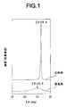
- FIG. 1 is a diagram showing the results of X-ray diffraction measurement of an amorphous carbon rod used for an anode in Example 1 and a graphite rod used for an anode in Comparative Example 1.
- FIG. FIG. 2 shows a mass loss percentage curve when the amorphous carbon rod used for the anode in Example 1 and the graphite rod used for the anode in Comparative Example 1 were heated in the atmosphere at a heating rate of 5 ° C./min.
- FIG. FIG. 3 shows an X-ray diffraction (XRD) profile of single-walled carbon nanotubes immediately after synthesis and after purification produced using an amorphous carbon rod as an anode in Example 1, and using a graphite rod as an anode in Comparative Example 1.
- XRD X-ray diffraction
- FIG. 4A is a scanning electron microscope (SEM) photograph (30000 times) of a purified single-walled carbon nanotube produced using an amorphous carbon rod as an anode in Example 1.
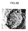
- FIG. 4B is shown in FIG. It is a SEM photograph (10000 time) which shows the part of the impurity of 4A single-walled carbon nanotube.
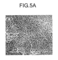
- FIG. 5A is an SEM photograph (30000 times) of the purified single-walled carbon nanotube produced using a graphite rod as the anode in Comparative Example 1.
- FIG. FIG. 5B is shown in FIG.
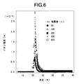
- FIG. 6 is a diagram showing a temperature-programmed desorption spectrum after exposing H 2 to the single-walled carbon nanotube sample of Example 1.
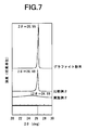
- FIG. 7 is a diagram showing the results of X-ray diffraction measurement of the amorphous carbon rod used for the anode in Example 2, the graphite rod used for the anode in Comparative Example 2, and the graphite powder as a reference example.
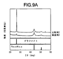
- FIG. 9A shows a crude soot produced using an amorphous carbon rod as an anode in Example 2, and a crude soot produced using a graphite rod as an anode in Comparative Example 2 immediately after synthesis from the top plate of the chamber ( It is a figure which shows the result of the X-ray-diffraction measurement of the cocoon of (before purification).
- FIG. 9A shows a crude soot produced using an amorphous carbon rod as an anode in Example 2, and a crude soot produced using a graphite rod as an anode in Comparative Example 2 immediately after synthesis from the top plate of the chamber ( It is a figure which shows the result of the X-ray-diffraction measurement of the cocoon of (before purification).
- FIG. 9B shows a crude soot produced using an amorphous carbon rod as an anode in Example 2, and a crude soot produced using a graphite rod as an anode in Comparative Example 2 immediately after synthesis from the inner wall of the chamber (purification). It is a figure which shows the result of the X-ray-diffraction measurement of the ridge of the front.
- FIG. 10A was obtained by collecting and purifying the crude iron produced using the amorphous carbon rod as the anode in Example 2 and the crude iron produced using the graphite rod as the anode in Comparative Example 2 from the top plate of the chamber. It is a figure which shows the result of X-ray diffraction measurement.
- FIG. 10A was obtained by collecting and purifying the crude iron produced using the amorphous carbon rod as the anode in Example 2 and the crude iron produced using the graphite rod as the anode in Comparative Example 2 from the top plate of the chamber. It is a figure which shows the result of X-ray
- 10B shows a crude soot produced using an amorphous carbon rod as an anode in Example 2, and a crude soot produced using a graphite rod as an anode in Comparative Example 2 from the inner surface of the side wall of the chamber and purified. It is a figure which shows the result of X-ray diffraction measurement.
- an amorphous material is produced during arc discharge.
- An anode mainly composed of carbon is used.
- an embodiment of a method for producing carbon nanotubes according to the present invention includes a step of producing an anode mainly composed of amorphous carbon, and a step of producing a soot containing single-walled carbon nanotubes by arc discharge using the anode.
- a first combustion oxidation step in which the soot containing the generated single-walled carbon nanotubes is heated and oxidized in the atmosphere at a temperature of 350 ° C. or higher, and the soot obtained in the first combustion oxidation step is converted into an acid.
- a first acid treatment step in which the soot is soaked and the soot obtained in the first acid treatment step is heated in the atmosphere at a temperature not lower than the heating temperature of the first combustion oxidation step and not lower than 500 ° C. for combustion
- the amorphous carbon rod used for the anode is preferably a carbon rod consisting essentially of amorphous carbon, but is a carbon rod mainly composed of amorphous carbon, preferably a carbon rod containing 50% by mass or more of amorphous carbon. If so, impurities and crystalline carbon may be included.
- soot containing carbon nanotubes is generated by arc discharge.
- the pair of electrodes to be attached to the chamber of the arc discharge device the above anode and a cathode made of a graphite rod are used.
- the temperature between the electrodes at the time of discharge reaches several thousand degrees Celsius, the carbon of the cathode is vaporized in the high temperature plasma, and the vaporized carbon is cooled and aggregated by the inert gas in the chamber, Soot accumulates in the chamber.
- Single-walled carbon nanotubes are contained in a large amount on the top plate of the chamber, on the inner wall and on the cathode, and multi-walled carbon nanotubes are contained in a soft black portion in the cathode deposit.
- First combustion oxidation process Next, the soot containing single-walled carbon nanotubes deposited on the top plate of the chamber, the upper part of the inner wall, and the cathode is collected.
- the soot collected in this way contains impurities such as amorphous carbon and graphite capsules containing metal in addition to single-walled carbon nanotubes.
- the impurities are burned and removed by heating at 350 to 550 ° C., more preferably 450 to 550 ° C., most preferably 500 ° C.
- the recovered soot may be heated in the atmosphere and then heated at a temperature higher than the heating temperature.
- the soot after heating is immersed in any acid such as hydrochloric acid, sulfuric acid, nitric acid, oxalic acid, left at room temperature, filtered, washed with distilled water, and dried. Residual metal catalyst can be removed.
- the obtained soot is heated at 500 ° C. or higher, preferably 500 to 600 ° C., more preferably 540 to 560 ° C., and most preferably 550 ° C. in the atmosphere to burn and remove impurities. In this way, graphite capsules other than single-walled carbon nanotubes can be burned and removed.
- (Second acid treatment step) Next, the soot after heating is immersed in hydrochloric acid and allowed to stand at room temperature, followed by filtration, washing with distilled water, and drying, whereby the metal catalyst remaining in the soot can be removed.
- the single-walled carbon nanotube thus purified after synthesis is heated in a vacuum at 1000 ° C. or higher, preferably 1000 to 1500 ° C., more preferably 1100 to 1300 ° C., and most preferably 1200 ° C.
- a defect of the carbon nanotube (defect generated in the single-walled carbon nanotube by the oxidation treatment) can be repaired.
- evaluation of carbon nanotube evaluation by Raman scattering spectroscopy
- the scattered light includes light v 0 having the same wave number as incident light (excitation light), and v 0 ⁇ v having a different wave number.
- the lattice vibration of carbon nanotubes is based on the vibration of graphite, but a new effect arises from the periodicity peculiar to carbon nanotubes.
- a vibration mode called a breathing mode appears. Since it is known that the frequency of this vibration mode is inversely proportional to the diameter of the tube, the distribution of the diameter of the tube can be known by measuring the frequency of the breathing mode by Raman scattering.
- the ratio (G / D ratio) of the spectrum intensity of the G band, which is a Raman band unique to carbon nanotubes, and the spectrum intensity of the D band derived from amorphous carbon (G / D ratio) is an index representing the purity of the single-walled carbon nanotube after synthesis. (Scale representing the degree of impurity contamination). (Evaluation by TEM image) From the TEM image of the single-walled carbon nanotube, it can be confirmed that the single-walled carbon nanotube forms a bundle and whether or not the wall surface of the single-walled carbon nanotube has a defect.
- the sample is dispersed with ultrasonic waves, sprayed onto a metal substrate with an airbrush, and then dried with a dryer to such an extent that it does not drip.
- a solvent such as ethanol
- the carbon nanotubes may be fixed to a metal substrate in the form of a sheet or film.
- the single-walled carbon nanotube manufactured in the embodiment of the carbon nanotube manufacturing method according to the present invention described above is adsorbed by blowing H 2 or D 2 as an adsorbed gas, and then increased at a temperature rising rate of 0.2 K / s.
- a disc was prepared.
- a 6 mm ⁇ 6 mm ⁇ 70 mm square bar (low graphitized carbon bar (amorphous carbon bar)) is prepared from this disc, and a hole having a diameter of 3.2 mm and a depth of 50 mm is formed in the center, and Fe, Ni , S (mass ratio 10: 10: 1) was filled with a metal catalyst made of a mixed powder to produce an anode.
- the produced anode and a cathode of a graphite rod (purity 99.9%) with a diameter of 16 mm are used, and a single layer is formed by the arc discharge method as follows. Carbon nanotubes were synthesized.
- the pair of electrodes is mounted in a chamber of an arc discharge device, the inside of the chamber is evacuated by a rotary pump, evacuated to 10 ⁇ 2 Torr, and then a direct current of 70 A is brought into contact with the anode and the cathode. And baked for 5 minutes to burn the filled metal catalyst powder and decompose hydrocarbons.
- the chamber is filled with helium gas up to 100 Torr, evacuated again to 10 -2 Torr, and then the chamber is filled with helium gas up to 100 Torr, and the distance between the electrodes is reduced to 3 mm.
- arc discharge was performed at a current of 90 A for 5 minutes.
- the arc discharge time depends on the length of the carbon rod of the anode, and the arc discharge current value is 2.5 A / mm 2 when the arc current density (arc current value per unit cross-sectional area of the anode) is 2.5 A / mm 2. It was adjusted to become.
- the soot collected in this manner contains impurities in addition to the single-walled carbon nanotubes, so the impurities were removed as follows. First, in order to remove amorphous carbon other than single-walled carbon nanotubes by combustion, the recovered soot is heated and oxidized in the atmosphere at 450 ° C. for 30 minutes, and then heated at 500 ° C. for 30 minutes for combustion oxidation. did. Next, the heated soot was immersed in 6N hydrochloric acid and allowed to stand at 60 ° C.
- the dried soot is again heated in the atmosphere at 500 ° C. for 30 minutes for combustion oxidation.
- the heated soot is immersed in 6N hydrochloric acid and left at 60 ° C. for 12 hours or longer, then filtered, and filtered at 60 ° C. Dried for 12 hours or more.
- the dried soot was heated (annealed) at 1200 ° C. for 3 hours in a vacuum of 10 ⁇ 7 Torr to obtain purified single-walled carbon nanotubes.
- Comparative Example 1 Example 1 described above except that instead of the amorphous carbon rod, a graphite rod (purity 99.9%) having a diameter of 3.2 mm and a hole having a depth of 85 mm formed with a diameter of 6 mm and a length of 100 mm was used. Single-walled carbon nanotubes were synthesized and purified by the same method.
- XRD X-ray diffraction
- the carbon rod used for the anode in Example 1 is a disordered layer having no regular layer structure. It can be seen that this is a low-graphitization carbon rod composed of a structure.
- the mass loss percentage curve when the amorphous carbon rod used for the anode in Example 1 and the graphite rod used for the anode in Comparative Example 1 were heated in the atmosphere at a heating rate of 5 ° C./min is shown in FIG. It is shown in 2.
- the oxidation start temperature of graphite is 700 ° C.
- the low graphitization carbon material has an oxidation start temperature of 400 to 600 ° C., depending on the degree of graphitization. In this way, the oxidation start temperature of the carbon material having a low graphitization degree is low.
- the turbulent layer structure that is not a graphite structure, many edges of graphene that are reaction fields with oxygen are exposed, This is because it is a graphene of the order of several nanometers, so that it becomes a thermally unstable structural state.
- FIG. As shown in FIG.
- the graphite rod used for the anode in Comparative Example 1 shows a mass reduction from about 700 ° C.
- the amorphous carbon rod used for the anode in Example 1 shows a mass reduction from about 500 ° C.
- the carbon rod used for the anode in Example 1 is a low-graphitization carbon rod composed of a turbulent layer structure having no regular layer structure.
- the XRD profiles of single-walled carbon nanotubes immediately after and after purification are shown in FIG. 3 shows.
- a scanning electron microscope (SEM) photograph of the purified single-walled carbon nanotube produced using an amorphous carbon rod for the anode in Example 1 is shown in FIG. 4A and FIG.
- FIG. 4B an SEM photograph of a purified single-walled carbon nanotube produced using a graphite rod as the anode in Comparative Example 1 is shown in FIG. 5A and FIG. Shown in 5B.
- FIG. 5A in addition to the observation of single-walled carbon nanotubes, FIG. As shown in 5B, a large lump of graphite of 10 to 30 ⁇ m was observed. The strong graphite peak in the XRD profile is thought to be due to this graphite mass. It is considered that the graphite lump is caused by the fact that the anode graphite rod at the time of arc discharge was not sublimated and was sputtered as graphite by arc discharge. On the other hand, FIG. As shown in FIG.
- single-walled carbon nanotubes were observed uniformly.
- an agglomerate having a size of 1 to 3 ⁇ m in which nanoparticles having a size of several nm considered to be graphite capsules covering the metal catalyst were agglomerated was observed.
- the peak intensity of graphite on the (002) plane in the X-ray diffraction (XRD) profile per unit mass of the single-walled carbon nanotubes immediately after synthesis and after purification was 2.6 cps / mg in the first measurement, The second measurement was 0 cps / mg and 80 cps / gm, respectively.
- the measurement of the peak intensity of graphite on the (002) plane in the X-ray diffraction (XRD) profile per unit mass of the single-walled carbon nanotubes immediately after the synthesis produced in Comparative Example 1 was performed twice.
- the Raman scattering spectroscopic measurement of single-walled carbon nanotubes immediately after synthesis and after purification which was produced using an amorphous carbon rod as the anode in Example 1, was performed twice.
- the Raman intensity ratio (D / G) of the single-walled carbon nanotubes immediately after synthesis and after purification was 23.5 and 85.0, respectively, in the first Raman scattering spectroscopy measurement, and the second Raman scattering spectroscopy. In the measurement, they were 40.0 and 100, respectively.
- the Raman scattering spectroscopic measurement of the single-walled carbon nanotubes immediately after synthesis and after purification produced in Comparative Example 1 was performed twice.
- the Raman intensity ratio (D / G) of the single-walled carbon nanotubes immediately after synthesis and after purification was 34.5 and 76.0, respectively, in the first Raman scattering spectroscopy measurement, and the second Raman scattering spectroscopy. In the measurement, they were 52.6 and 80.0, respectively.
- the purified single-walled carbon nanotube produced using an amorphous carbon rod as the anode in Example 1 has a very high Raman intensity ratio (D / G) of 85 to 100 and a purity of It is very high. This means that the amount of graphite in the unit volume is very small, so that impurities are very small and the purity of the carbon nanotube is very high.
- the sample length (tube length) was about 1 to 3 ⁇ m, and the total length of the tube was relatively long. It was a single-walled carbon nanotube called a junction type.
- the single-walled carbon nanotube obtained in Example 1 is a carbon nanotube having no defects or almost no defects. Also, a quadrupole mass spectrometer for temperature programmed desorption spectrum measurement and a gas dozer having an orifice (pore) with a diameter of 20 ⁇ m for gas exposure for directly blowing gas onto a sample fixed to a metal substrate were provided.
- Example 1 the temperature of the sample of the single-walled carbon nanotube obtained in Example 1 is maintained at 13K, and H 2 or D 2 is sprayed on each sample as an adsorbed gas at a flow rate of 1 L / s to be adsorbed. Thereafter, the temperature was increased at a rate of temperature increase of 0.2 K / s, and the temperature-programmed desorption spectrum was measured.
- the recovery rate of the purified single-walled carbon nanotubes produced using the amorphous carbon rod for the anode in Example 1 is 5 to 10% by mass with respect to the single-walled carbon nanotubes immediately after synthesis, and the purity is 99. % Or more (0.5% by mass or less of metal, 0.5% by mass or less of carbon nanocapsules).
- Comparative Example 2 Petroleum needle-shaped coke mixed with particle size is blended with a coal tar pitch (binding material) with a softening point of 98 ° C. and fixed carbon of 58% as a binder at a ratio of 30% by mass, and thoroughly mixed at 140 ° C. with a Werner compounding machine. Thus, a uniform paste was produced.
- This paste was filled in a container of an extrusion molding apparatus, and an axial core mandrel was attached to a cylindrical nozzle to obtain a molded body with an extrusion pressure of 40 kg / cm 2 or more.
- This molded body was placed in a firing furnace and calcined at 1000 ° C., and then placed in an LWG furnace, graphitized at 3000 ° C., diameter 6 mm, length 100 mm, center diameter 3.2 mm, depth A rod having a 70 mm hole (graphite rod) was obtained.
- iron powder 100 mesh iron powder manufactured by Wako Pure Chemical Industries, Ltd.
- nickel powder 100 mesh nickel powder manufactured by Wako Pure Chemical Industries, Ltd.
- sulfur High Purity 5 manufactured by Mitsuwa Chemicals Co., Ltd.
- graphite powder manufactured by Wako Pure Chemical Industries, Ltd.
- CFx Poly (carbon monofluoride)
- a metal catalyst comprising a mixed powder having a ratio of 30: 10: 10: 1: 1) was prepared, and the anode was prepared by filling the metal catalyst into a hole of a graphite rod.
- the produced anode and a cathode of a graphite rod (purity 99.9%) with a diameter of 16 mm are used, and a single layer is formed by the arc discharge method as follows. Carbon nanotubes were synthesized.
- the above-mentioned pair of electrodes is mounted in a chamber of an arc discharge device, the inside of the chamber is evacuated by a rotary pump and evacuated to 10 ⁇ 2 Torr, and then 28.6A ( A current density of 1.01 A / mm 2 ) for 3 minutes, a current of 37.9 A (current density of 1.34 A / mm 2 ) for 3 minutes, and a current of 47.5 A (current density of 1.68 A / mm 2 ). 3 minutes, 56.8A (current density 2.01A / mm 2) current 3 minutes, an annealing treatment was performed by applying a current of 66.4A (current density 2.35A / mm 2) 5 min.
- the current density is a current value per unit cross-sectional area of the anode, and is a value obtained by dividing the current value by the cross-sectional area of the rod 28.26 mm 2 .
- the chamber was filled with helium gas up to 100 Torr, and an arc discharge was performed by flowing a current of 75.8 A (current density 2.68 A / mm 2 ) while maintaining the distance between the electrodes at 3 mm.
- This arc discharge ended when the anode was consumed to some extent.
- soot accumulated on the top plate and side wall inner surface of the chamber was collected.
- the soot collected in this manner contains impurities in addition to the single-walled carbon nanotubes, so the impurities were removed as follows.
- the collected soot is put in a SUS container with good air permeability, installed in a muffle furnace (FM37 manufactured by Yamato Scientific Co., Ltd.), and 450% in the air.
- the mixture was heated and oxidized at 30 ° C. for 30 minutes, followed by combustion and oxidation at 500 ° C. for 30 minutes.
- the soot after combustion oxidation is put into the screw robin, and a 6N hydrochloric acid solution (35.0 to 37.0% by mass of reagent special grade hydrochloric acid manufactured by Wako Pure Chemical Industries, Ltd.) and purified water are mixed at a volume of 1: 1.
- a disc was prepared.
- a 6 mm ⁇ 6 mm ⁇ 70 mm square bar (low graphitized carbon bar (amorphous carbon bar)) was produced from this disc, and a hole having a diameter of 3.2 mm and a depth of 50 mm was formed in the center.
- the corner of this square bar was dropped with sandpaper to make an octagonal cross section. Comparative Example 2 except that instead of graphite powder (manufactured by Wako Pure Chemical Industries, Ltd.), the powder produced when a hole was made in an amorphous carbon rod and the corner was dropped to be processed into an octagonal rod was used.
- An anode was prepared by filling a hole of an amorphous carbon rod with a metal catalyst made of the same mixed powder as in Example 1. Next, using the produced anode, a current of 30.0 A (current density 1.01 A / mm 2 ) was applied for 3 minutes, a current of 40.0 A (current density 1.34 A / mm 2 ) was applied for 3 minutes, 50 0.0A (current density 1.68 A / mm 2 ) for 3 minutes, 60.0 A (current density 2.01 A / mm 2 ) for 3 minutes, 70.0 A (current density 2.35 A / mm 2 ) Comparative Example 2 except that an annealing treatment was performed by flowing a current of 5 minutes, and an arc discharge was performed by flowing a current of 80.0 A (current density 2.68 A / mm 2 ) in a state where the anode and the cathode were in contact with each other.
- the soot containing the synthesized single-walled carbon nanotubes was collected by the same method.
- the current density is a value obtained by dividing the current value by the cross-sectional area of the rod 29.82 mm 2 . Since the soot collected in this manner contains impurities in addition to the single-walled carbon nanotubes, the purified single-walled carbon nanotubes are removed by removing impurities by the same method as in Comparative Example 2. Obtained.
- the average spacing d of these (002) planes is 0.3357 nm and 0.3366 nm, respectively, which is in good agreement with the theoretical diffraction angle of the XRD profile of graphite and the average spacing d of the (002) plane. From these facts, it can be said that the graphite crystal structure is highly developed.
- the value smaller than the average interplanar spacing d of (002) plane of hexagonal graphite is that the diffraction angle of rhombohedral graphite is 26.60 °, and the average interplanar spacing d of (002) plane. Is 0.3349 nm, it is considered that this is because rhombohedral graphite exists. This is considered to be because when graphite powder having a highly developed graphite structure is refined, stress is applied to the structure and the structure is transferred to rhombohedral graphite.
- FIG. As shown in FIG.
- the amorphous carbon rod used for the anode in Example 2 the graphite rod used for the anode in Comparative Example 2, and the graphite powder as a reference example (manufactured by Wako Pure Chemical Industries, Ltd.) in the atmosphere at a temperature rising rate of 5
- the mass loss percentage curve when the temperature is raised at 0 ° C./min is shown in FIG. It is shown in FIG.
- the carbon substance reacts with oxygen, CO and CO 2 are generated. Therefore, it is possible to investigate at which temperature the carbon substance reacts with oxygen by mass thermal analysis of the carbon material in the atmosphere.
- the oxidation start temperature of graphite is 700 ° C.
- the low graphitization carbon material has an oxidation start temperature of 400 to 600 ° C., depending on the degree of graphitization. In this way, the oxidation start temperature of the carbon material having a low graphitization degree is low.
- the turbulent layer structure that is not a graphite structure, many edges of graphene that are reaction fields with oxygen are exposed, This is because it is a graphene of the order of several nanometers, so that it becomes a thermally unstable structural state.
- FIG. As shown in FIG. 8, in the graphite powder as a reference example and the graphite rod used for the anode in Comparative Example 2, a mass reduction is observed from about 600 ° C.
- the amorphous carbon rod used for the anode in Example 2 mass reduction is recognized from about 500 ° C. Also from these results, it can be seen that the amorphous carbon rod used for the anode in Example 2 is a low-graphitization carbon rod composed of a turbulent layer structure having no regular layer structure. (Evaluation of single-walled carbon nanotubes produced in Example 2 and Comparative Example 2) Immediately after synthesizing the crude soot produced using an amorphous carbon rod as the anode in Example 2 and the crude soot produced using the graphite rod as the anode in Comparative Example 2 (before purification), respectively.
- X-ray diffraction (XRD) profile of The X-ray diffraction (XRD) profile of the soot immediately after synthesis (before purification) in which the crude soot produced using these amorphous carbon rods and graphite rods is recovered from the inner surface of the side wall of the chamber is shown in FIG. Shown in 9B.
- the crude soot produced using an amorphous carbon rod as the anode in Example 2 and the crude soot produced using the graphite rod as the anode in Comparative Example 2 were recovered from the top plate of the chamber and purified.
- X-ray diffraction (XRD) profile is shown in FIG. FIG.
- 10A shows the X-ray diffraction (XRD) profile of the soot that was obtained by collecting the crude soot produced using these amorphous carbon rods and graphite rods from the inner surface of the side wall of the chamber and purifying them. Shown in 10B.
- the crude soot produced using an amorphous carbon rod as the anode in Example 2 and the crude soot produced using the graphite rod as the anode in Comparative Example 2 were collected from the inner surface of the side wall of the chamber immediately after the synthesis (before purification). ) was observed with a scanning electron microscope (SEM).
- Particles having a diameter of about 30 to 150 nm and small particles having a diameter of about 10 nm were observed.
- Particles with a diameter of about 30 to 150 nm are considered to be particles mixed by sputtering from the anode, and particles with a diameter of about 10 nm are considered to be graphite generated from atomic carbon evaporated and sublimated by arc discharge. It is done.
- the crude soot produced using the amorphous carbon rod as the anode in Example 2 and the crude soot produced using the graphite rod as the anode in Comparative Example 2 were collected from the inner surface of the side wall of the chamber (purification). The Raman scattering spectroscopic measurement of the cocoon before and after purification was performed.
- Example 2 the Raman intensity ratio (D / G) of soot immediately after synthesis (before purification) and after purification was 13.8 to 14.1 and 92.7 to 113.2, respectively.
- Table 3 the crude strength produced using the amorphous carbon rod as the anode in Example 2 was recovered from the inner surface of the side wall of the chamber and purified, and the Raman intensity ratio (D / G) was 92.7. It is very high at ⁇ 113.2 and the purity is very high. This means that the amount of graphite in the unit volume is very small, so that impurities are very small and the purity of the carbon nanotube is very high.
Landscapes
- Chemical & Material Sciences (AREA)
- Engineering & Computer Science (AREA)
- Nanotechnology (AREA)
- Materials Engineering (AREA)
- Organic Chemistry (AREA)
- Inorganic Chemistry (AREA)
- General Physics & Mathematics (AREA)
- Physics & Mathematics (AREA)
- Condensed Matter Physics & Semiconductors (AREA)
- Crystallography & Structural Chemistry (AREA)
- Chemical Kinetics & Catalysis (AREA)
- Manufacturing & Machinery (AREA)
- Composite Materials (AREA)
- Health & Medical Sciences (AREA)
- General Health & Medical Sciences (AREA)
- Toxicology (AREA)
- Carbon And Carbon Compounds (AREA)
Abstract
L'invention porte sur des nanotubes de carbone de haute pureté qui peuvent être produits par simple purification par la mise en œuvre d'une synthèse par décharge en arc de sorte qu'il n'y a pratiquement pas de graphite dans les suies brutes obtenues immédiatement après la synthèse. L'invention porte également sur un procédé pour la production des nanotubes de carbone. Des suies contenant des nanotubes de carbone qui ont été produites par décharge en arc à l'aide d'une anode comprenant du carbone amorphe comme composant principal sont brûlées et oxydées par chauffage des suies dans l'air à une température supérieure ou égale à 350°C, ensuite elles sont traitées par immersion dans un acide, et par la suite brûlées et oxydées par chauffage des suies dans l'air à une température qui n'est pas inférieure à la température de chauffage utilisée dans la combustion/oxydation précédente et qui est supérieure ou égale à 500°C, puis à nouveau traitées par immersion dans un acide.
Priority Applications (3)
| Application Number | Priority Date | Filing Date | Title |
|---|---|---|---|
| EP10786116.3A EP2431325B1 (fr) | 2009-06-11 | 2010-05-28 | Procédé de production de nanotubes de carbone |
| CN201080026367.0A CN102459073B (zh) | 2009-06-11 | 2010-05-28 | 碳纳米管及其制造方法 |
| US13/376,564 US8858909B2 (en) | 2009-06-11 | 2010-05-28 | Carbon nanotube and method for producing same |
Applications Claiming Priority (4)
| Application Number | Priority Date | Filing Date | Title |
|---|---|---|---|
| JP2009-139927 | 2009-06-11 | ||
| JP2009139927 | 2009-06-11 | ||
| JP2010-116874 | 2010-05-21 | ||
| JP2010116874A JP5647435B2 (ja) | 2009-06-11 | 2010-05-21 | カーボンナノチューブおよびその製造方法 |
Publications (1)
| Publication Number | Publication Date |
|---|---|
| WO2010143585A1 true WO2010143585A1 (fr) | 2010-12-16 |
Family
ID=43308840
Family Applications (1)
| Application Number | Title | Priority Date | Filing Date |
|---|---|---|---|
| PCT/JP2010/059492 Ceased WO2010143585A1 (fr) | 2009-06-11 | 2010-05-28 | Nanotubes de carbone et leur procédé de production |
Country Status (5)
| Country | Link |
|---|---|
| US (1) | US8858909B2 (fr) |
| EP (1) | EP2431325B1 (fr) |
| JP (1) | JP5647435B2 (fr) |
| CN (1) | CN102459073B (fr) |
| WO (1) | WO2010143585A1 (fr) |
Cited By (1)
| Publication number | Priority date | Publication date | Assignee | Title |
|---|---|---|---|---|
| CN102602911A (zh) * | 2012-03-07 | 2012-07-25 | 上海交通大学 | 一种采用低压反应性气体可控性制备单壁碳纳米管的方法 |
Families Citing this family (26)
| Publication number | Priority date | Publication date | Assignee | Title |
|---|---|---|---|---|
| ES3065468T3 (en) | 2009-04-17 | 2026-05-06 | Seerstone Llc | Method for producing solid carbon by reducing carbon oxides |
| NO2749379T3 (fr) | 2012-04-16 | 2018-07-28 | ||
| EP2838839B1 (fr) | 2012-04-16 | 2020-08-12 | Seerstone LLC | Procédé de production de carbone solide par réduction du dioxyde de carbone |
| MX354526B (es) | 2012-04-16 | 2018-03-07 | Seerstone Llc | Metodos y sistemas para capturar y secuestrar carbono y para reducir la masa de oxidos de carbono en una corriente de gas de desechos. |
| WO2013158158A1 (fr) | 2012-04-16 | 2013-10-24 | Seerstone Llc | Procédé de traitement d'un dégagement gazeux contenant des oxydes de carbone |
| US9796591B2 (en) | 2012-04-16 | 2017-10-24 | Seerstone Llc | Methods for reducing carbon oxides with non ferrous catalysts and forming solid carbon products |
| US9896341B2 (en) | 2012-04-23 | 2018-02-20 | Seerstone Llc | Methods of forming carbon nanotubes having a bimodal size distribution |
| JP6284934B2 (ja) | 2012-07-12 | 2018-02-28 | シーアストーン リミテッド ライアビリティ カンパニー | カーボンナノチューブを含む固体炭素生成物およびそれを形成する方法 |
| US10815124B2 (en) | 2012-07-12 | 2020-10-27 | Seerstone Llc | Solid carbon products comprising carbon nanotubes and methods of forming same |
| CN107215882A (zh) | 2012-07-13 | 2017-09-29 | 赛尔斯通股份有限公司 | 用于形成氨和固体碳产物的方法和系统 |
| US9779845B2 (en) | 2012-07-18 | 2017-10-03 | Seerstone Llc | Primary voltaic sources including nanofiber Schottky barrier arrays and methods of forming same |
| WO2014085378A1 (fr) | 2012-11-29 | 2014-06-05 | Seerstone Llc | Réacteurs et procédés de production de matériaux de carbone solides |
| WO2014151138A1 (fr) | 2013-03-15 | 2014-09-25 | Seerstone Llc | Réacteurs, systèmes et procédés de formation de produits solides |
| EP3129133B1 (fr) | 2013-03-15 | 2024-10-09 | Seerstone LLC | Systèmes de production de carbone solide par réduction d'oxydes de carbone |
| EP3113880A4 (fr) | 2013-03-15 | 2018-05-16 | Seerstone LLC | Reduction d'oxyde de carbone par des catalyseurs intermetalliques et de carbure |
| EP3129321B1 (fr) | 2013-03-15 | 2021-09-29 | Seerstone LLC | Electrodes comprenant du carbone en nanostructure |
| WO2014150944A1 (fr) | 2013-03-15 | 2014-09-25 | Seerstone Llc | Procédés de production d'hydrogène et de carbone solide |
| WO2018022999A1 (fr) | 2016-07-28 | 2018-02-01 | Seerstone Llc. | Produits solides en carbone comprenant des nanotubes de carbone comprimés dans un récipient et procédés pour leur formation |
| CN108808025A (zh) * | 2018-07-04 | 2018-11-13 | 南京邮电大学 | 一种碳纳米管负载氧化铁氧还原催化剂的制备方法 |
| JP7098449B2 (ja) * | 2018-07-11 | 2022-07-11 | 国立大学法人東北大学 | カーボンナノチューブ含有スズドープ酸化インジウム膜およびその製造方法 |
| JP7098448B2 (ja) * | 2018-07-11 | 2022-07-11 | 国立大学法人東北大学 | カーボンナノチューブ含有スズドープ酸化インジウム膜およびその製造方法 |
| CN110589805B (zh) * | 2019-10-30 | 2021-02-19 | 山东大展纳米材料有限公司 | 一种电弧活化碳纳米管后经cvd制备碳气凝胶的装置及方法 |
| CN114014300A (zh) * | 2021-11-24 | 2022-02-08 | 深圳市飞墨科技有限公司 | 碳纳米管及其纯化方法 |
| CN114890407B (zh) * | 2022-05-31 | 2023-09-19 | 江西铜业技术研究院有限公司 | 一种等离子体制备单壁碳纳米管的装置和方法 |
| CN121591201A (zh) * | 2024-08-21 | 2026-03-03 | 江西紫宸科技有限公司 | 一种单壁碳纳米管的纯化方法、高纯单壁碳纳米管及其应用 |
| JP7796290B1 (ja) * | 2025-01-30 | 2026-01-08 | 住友化学株式会社 | カーボンナノチューブ集合体、導電材料、電極、二次電池、平面状集合体、積層体、フィルター、電磁波シールド、及び極端紫外線用ペリクル |
Citations (4)
| Publication number | Priority date | Publication date | Assignee | Title |
|---|---|---|---|---|
| JP2003081616A (ja) * | 2001-07-05 | 2003-03-19 | Honda Motor Co Ltd | 単層カーボンナノチューブの精製方法 |
| JP2004210555A (ja) | 2002-12-27 | 2004-07-29 | Hitachi Powdered Metals Co Ltd | カーボンナノチューブの製造方法 |
| JP2005022902A (ja) * | 2003-06-30 | 2005-01-27 | Toyo Tanso Kk | 金属−炭素複合材料 |
| JP2006016282A (ja) | 2004-07-05 | 2006-01-19 | Shinzo Suzuki | 単層カーボンナノチューブの製造法 |
Family Cites Families (7)
| Publication number | Priority date | Publication date | Assignee | Title |
|---|---|---|---|---|
| CN1101335C (zh) * | 1999-06-16 | 2003-02-12 | 中国科学院金属研究所 | 一种大量制备单壁纳米碳管的氢弧放电方法 |
| US6752977B2 (en) * | 2001-02-12 | 2004-06-22 | William Marsh Rice University | Process for purifying single-wall carbon nanotubes and compositions thereof |
| US7008605B1 (en) * | 2001-11-08 | 2006-03-07 | The United States Of America As Represented By The Administrator Of The National Aeronautics And Space Administration | Method for manufacturing high quality carbon nanotubes |
| JP3997930B2 (ja) * | 2003-02-27 | 2007-10-24 | 富士ゼロックス株式会社 | カーボンナノチューブの製造装置および製造方法 |
| CN1299980C (zh) * | 2004-06-15 | 2007-02-14 | 南开大学 | 单壁碳纳米管的电弧合成方法 |
| CN100522804C (zh) * | 2005-10-18 | 2009-08-05 | 南开大学 | 一种电弧法合成可控单壁碳纳米管的方法 |
| US7955663B2 (en) * | 2006-12-04 | 2011-06-07 | Council Of Scientific And Industrial Research | Process for the simultaneous and selective preparation of single-walled and multi-walled carbon nanotubes |
-
2010
- 2010-05-21 JP JP2010116874A patent/JP5647435B2/ja not_active Expired - Fee Related
- 2010-05-28 US US13/376,564 patent/US8858909B2/en active Active
- 2010-05-28 EP EP10786116.3A patent/EP2431325B1/fr active Active
- 2010-05-28 WO PCT/JP2010/059492 patent/WO2010143585A1/fr not_active Ceased
- 2010-05-28 CN CN201080026367.0A patent/CN102459073B/zh not_active Expired - Fee Related
Patent Citations (4)
| Publication number | Priority date | Publication date | Assignee | Title |
|---|---|---|---|---|
| JP2003081616A (ja) * | 2001-07-05 | 2003-03-19 | Honda Motor Co Ltd | 単層カーボンナノチューブの精製方法 |
| JP2004210555A (ja) | 2002-12-27 | 2004-07-29 | Hitachi Powdered Metals Co Ltd | カーボンナノチューブの製造方法 |
| JP2005022902A (ja) * | 2003-06-30 | 2005-01-27 | Toyo Tanso Kk | 金属−炭素複合材料 |
| JP2006016282A (ja) | 2004-07-05 | 2006-01-19 | Shinzo Suzuki | 単層カーボンナノチューブの製造法 |
Non-Patent Citations (2)
| Title |
|---|
| PARK Y S ET AL.: "Low pressure synthesis of single-walled carbon nanotubes by arc discharge", SYNTH MET, vol. 126, no. 2-3, 14 February 2002 (2002-02-14), pages 245 - 251, XP008148944 * |
| S. IWATA ET AL.: "Novel Method to Evaluate the Carbon Network of Single-Walled Carbon Nanotubes by Hydrogen Physisorption", THE JOURNAL OF PHYSICAL CHEMISTRY C LETTERS, vol. 111, 22 September 2007 (2007-09-22), pages 14937 - 14941, XP008148946 * |
Cited By (1)
| Publication number | Priority date | Publication date | Assignee | Title |
|---|---|---|---|---|
| CN102602911A (zh) * | 2012-03-07 | 2012-07-25 | 上海交通大学 | 一种采用低压反应性气体可控性制备单壁碳纳米管的方法 |
Also Published As
| Publication number | Publication date |
|---|---|
| EP2431325A1 (fr) | 2012-03-21 |
| EP2431325A4 (fr) | 2016-04-27 |
| JP2011016711A (ja) | 2011-01-27 |
| CN102459073A (zh) | 2012-05-16 |
| CN102459073B (zh) | 2014-05-14 |
| US8858909B2 (en) | 2014-10-14 |
| US20120083408A1 (en) | 2012-04-05 |
| JP5647435B2 (ja) | 2014-12-24 |
| EP2431325B1 (fr) | 2019-12-04 |
Similar Documents
| Publication | Publication Date | Title |
|---|---|---|
| JP5647435B2 (ja) | カーボンナノチューブおよびその製造方法 | |
| JP5424481B2 (ja) | カーボンナノチューブを含んだ炭素材料の精製方法 | |
| Zhu et al. | The design and construction of 3D rose-petal-shaped MoS2 hierarchical nanostructures with structure-sensitive properties | |
| JP5253943B2 (ja) | 導電性材料およびその製造方法 | |
| KR101105473B1 (ko) | 신규한 구조의 탄소계 나노복합체 및 이의 제조방법 | |
| JP5599204B2 (ja) | カーボンナノチューブ集合体及びその製造方法 | |
| JP2008069015A (ja) | 薄片炭素粒子及びその製造方法 | |
| CN101977841B (zh) | 碳纳米管的制造方法 | |
| JP2023134066A (ja) | 多孔質炭素材料の製造方法 | |
| CN101631744A (zh) | 含有碳纳米管的碳材料的精制方法及由该精制方法得到的碳材料、以及使用该碳材料的树脂成型体、纤维、散热器、滑动材料、电场电子释放源材料、电极的导电助剂、担载有催化剂的材料及导电性膜 | |
| Fedorovskaya et al. | Effect of oxidative treatment on the electrochemical properties of aligned multi-walled carbon nanotubes | |
| JP5330035B2 (ja) | カーボンナノチューブおよびその製造方法 | |
| JP5330034B2 (ja) | カーボンナノチューブの評価方法 | |
| JP4761346B2 (ja) | 2層カーボンナノチューブ含有組成物 | |
| Rajesh et al. | Lanthanum nickel alloy catalyzed growth of nitrogen-doped carbon nanotubes by chemical vapor deposition | |
| KR100514186B1 (ko) | 고비표면적 탄소재 | |
| JP3914179B2 (ja) | カーボンナノファイバーの構造制御方法 | |
| JP2005154200A (ja) | カーボンナノチューブの製造方法 | |
| KR100726368B1 (ko) | 섬유상 나노탄소 | |
| JP5280217B2 (ja) | 金属−炭素複合材料 | |
| Raghubanshi et al. | Synthesis of carbon nanostructures using hydrogen storage alloys as catalysts | |
| JP2024090957A (ja) | 黒鉛材料及び黒鉛材料の製造方法 | |
| CN119522190A (zh) | 从固体碳源生产高质量石墨烯 | |
| JP2010126403A (ja) | ナノ炭素材料複合体及びその製造方法 | |
| JP2004307272A (ja) | カーボンナノチューブを製造するためのアーク放電用炭素材料および製造方法 |
Legal Events
| Date | Code | Title | Description |
|---|---|---|---|
| WWE | Wipo information: entry into national phase |
Ref document number: 201080026367.0 Country of ref document: CN |
|
| 121 | Ep: the epo has been informed by wipo that ep was designated in this application |
Ref document number: 10786116 Country of ref document: EP Kind code of ref document: A1 |
|
| WWE | Wipo information: entry into national phase |
Ref document number: 2010786116 Country of ref document: EP |
|
| WWE | Wipo information: entry into national phase |
Ref document number: 13376564 Country of ref document: US |
|
| NENP | Non-entry into the national phase |
Ref country code: DE |