WO2010143691A1 - Appareil de diagnostic - Google Patents
Appareil de diagnostic Download PDFInfo
- Publication number
- WO2010143691A1 WO2010143691A1 PCT/JP2010/059855 JP2010059855W WO2010143691A1 WO 2010143691 A1 WO2010143691 A1 WO 2010143691A1 JP 2010059855 W JP2010059855 W JP 2010059855W WO 2010143691 A1 WO2010143691 A1 WO 2010143691A1
- Authority
- WO
- WIPO (PCT)
- Prior art keywords
- measurement
- network analyzer
- vector network
- diagnostic apparatus
- antennas
- Prior art date
- Legal status (The legal status is an assumption and is not a legal conclusion. Google has not performed a legal analysis and makes no representation as to the accuracy of the status listed.)
- Ceased
Links
Images







Classifications
-
- A—HUMAN NECESSITIES
- A61—MEDICAL OR VETERINARY SCIENCE; HYGIENE
- A61B—DIAGNOSIS; SURGERY; IDENTIFICATION
- A61B10/00—Instruments for taking body samples for diagnostic purposes; Other methods or instruments for diagnosis, e.g. for vaccination diagnosis, sex determination or ovulation-period determination; Throat striking implements
- A61B10/0041—Detection of breast cancer
-
- A—HUMAN NECESSITIES
- A61—MEDICAL OR VETERINARY SCIENCE; HYGIENE
- A61B—DIAGNOSIS; SURGERY; IDENTIFICATION
- A61B5/00—Measuring for diagnostic purposes; Identification of persons
- A61B5/05—Detecting, measuring or recording for diagnosis by means of electric currents or magnetic fields; Measuring using microwaves or radio waves
- A61B5/0507—Detecting, measuring or recording for diagnosis by means of electric currents or magnetic fields; Measuring using microwaves or radio waves using microwaves or terahertz waves
-
- A—HUMAN NECESSITIES
- A61—MEDICAL OR VETERINARY SCIENCE; HYGIENE
- A61B—DIAGNOSIS; SURGERY; IDENTIFICATION
- A61B5/00—Measuring for diagnostic purposes; Identification of persons
- A61B5/05—Detecting, measuring or recording for diagnosis by means of electric currents or magnetic fields; Measuring using microwaves or radio waves
- A61B5/053—Measuring electrical impedance or conductance of a portion of the body
- A61B5/0536—Impedance imaging, e.g. by tomography
-
- A—HUMAN NECESSITIES
- A61—MEDICAL OR VETERINARY SCIENCE; HYGIENE
- A61B—DIAGNOSIS; SURGERY; IDENTIFICATION
- A61B90/00—Instruments, implements or accessories specially adapted for surgery or diagnosis and not covered by any of the groups A61B1/00 - A61B50/00, e.g. for luxation treatment or for protecting wound edges
- A61B90/10—Instruments, implements or accessories specially adapted for surgery or diagnosis and not covered by any of the groups A61B1/00 - A61B50/00, e.g. for luxation treatment or for protecting wound edges for stereotaxic surgery, e.g. frame-based stereotaxis
- A61B90/14—Fixators for body parts, e.g. skull clamps; Constructional details of fixators, e.g. pins
- A61B90/17—Fixators for body parts, e.g. skull clamps; Constructional details of fixators, e.g. pins for soft tissue, e.g. breast-holding devices
-
- A—HUMAN NECESSITIES
- A61—MEDICAL OR VETERINARY SCIENCE; HYGIENE
- A61B—DIAGNOSIS; SURGERY; IDENTIFICATION
- A61B17/00—Surgical instruments, devices or methods
- A61B17/30—Surgical pincettes, i.e. surgical tweezers without pivotal connections
- A61B2017/306—Surgical pincettes, i.e. surgical tweezers without pivotal connections holding by means of suction
-
- A—HUMAN NECESSITIES
- A61—MEDICAL OR VETERINARY SCIENCE; HYGIENE
- A61B—DIAGNOSIS; SURGERY; IDENTIFICATION
- A61B2562/00—Details of sensors; Constructional details of sensor housings or probes; Accessories for sensors
- A61B2562/14—Coupling media or elements to improve sensor contact with skin or tissue
- A61B2562/143—Coupling media or elements to improve sensor contact with skin or tissue for coupling microwaves
Definitions
- the present invention relates to a diagnostic apparatus used for diagnosis of abnormal cells such as early breast cancer.
- Non-Patent Document 1 is a monostatic radar that irradiates a breast with broadband pulses from many directions and receives them in the same direction, and obtains a three-dimensional scattered electric field distribution by spatio-temporal directivity synthesis.
- Non-Patent Document 2 is a multi-static radar that receives a response of a pulse emitted from a certain direction by a plurality of antennas at different positions. The irradiation direction is changed, and reception is performed by a plurality of antennas each time.
- the Capon method known as an adaptive beam forming algorithm is used to improve the resolution of Non-Patent Document 1 by directivity synthesis so that responses other than the corresponding pixel are zero.
- Non-Patent Document 3 irradiates a breast with a narrow-band electromagnetic wave and receives it by a plurality of antennas at different locations.
- a propagation model eg, a model consisting of skin, adipose tissue, mammary gland, and cancer
- the received response to a transmitted signal can be calculated based on Maxwell's equations.
- a propagation model is estimated from a received signal by solving an inverse problem.
- Patent Document 1 relating to tomography using electromagnetic waves uses an electromagnetic coil instead of the antenna of Non-Patent Document 3 in order to avoid an increase in size of the antenna due to the wavelength of the electromagnetic waves. Is the same as Non-Patent Document 3.
- Non-Patent Documents 1, 2, and 3 as shown in FIG. 24, the antenna 51 and the breast 53 are immersed in a matching medium 52 that is close to the electromagnetic parameters of the normal tissue of the breast to obtain impedance matching. Increasing the amount of electromagnetic waves transmitted to the inside. In this case, the subject becomes prone and is examined in a posture in which the breast is suspended. The reflection of electromagnetic waves from the skin cannot be completely removed using matching media.
- the response from cancer is very small and is buried in the response of reflection from the skin.
- Non-Patent Document 3 also requires prior knowledge of the three-dimensional shape of the imaging region. In order to remove artifacts such as reflection from the skin, it is effective to average a plurality of responses having the same distance relationship between the transmitting and receiving antennas and the skin and subtract them from the received signal.
- the shape of the breast varies greatly from person to person, and it is difficult to keep the distance between the antenna and the skin constant. For this reason, it is necessary to measure the distance between the breast and the antenna and correct the received signal according to the measurement distance.
- Non-Patent Document 4 For the measurement of the distance between the breast and the antenna, a method using a UWB radar and a method using a laser radar are considered.
- the antenna is helically scanned while irradiating a broadband pulse of 1 to 11 GHz, 40 measurement data are acquired, and interpolation is performed at 1000 points to estimate the three-dimensional shape of the breast.
- Non-Patent Document 5 reports that UWB radar and laser radar are rotationally scanned while changing the height to estimate the three-dimensional shape of the breast, and that laser radar has higher estimation accuracy.
- Patent Document 2 describes a method in which an X-ray film is placed on one of the molds matched to the breast and X-rays are irradiated from the opposite side.
- Patent Document 3 describes a method of adjusting the shape of an imaging unit by placing a breast in a mold and further sucking it with a vacuum pump in order to fix the position of the breast during X-ray imaging.
- Patent Document 4 describes a method of imaging by attaching various sensors (light, X-rays, electromagnetic waves, ultrasonic waves, magnetism, impedance) to the inside of a rigid surface and closely contacting the imaging unit.
- Patent Documents 2 and 3 Conventional screening techniques for early breast cancer have the following problems.
- the X-ray source is separated from the mold for fixing the breast, and the positioning mechanism is large.
- X-ray mammography has the disadvantages of X-ray exposure and low contrast, has a large apparatus size, requires an X-ray radiologist, and is expensive as a diagnostic means.
- Patent Document 4 mentions only the adhesion between the sensor and the imaging unit, assuming application to ultrasonic waves and impedance CT.
- the impedance characteristic of the antenna is changed, the reflection loss is increased, and the electromagnetic wave does not travel inside the imaging unit, so that a response required for imaging cannot be obtained.
- Non-Patent Documents 1 and 3 it is predicted that it will be difficult to find an initial cancer of several millimeters due to insufficient resolution. No clinical imaging has been reported in Literature 1, and only imaging results of advanced cancer with a diameter of 4 cm are reported in Literature 3.
- Non-Patent Document 2 has a higher resolution than the method of Non-Patent Document 1, but includes parameters that are not uniquely determined in the middle of the calculation process, so if the parameters are not set appropriately, imaging fails. Also, the amount of calculation is large, and enormous time is required to obtain a final diagnostic image.
- the dielectric constant or conductivity distribution of the diagnostic region is obtained by an inverse problem from a plurality of reception responses.
- the inverse problem is generally an ill-posed problem and is often optimized by the Tikhonov method.
- Tihonov's method includes parameters that cannot be uniquely determined, and imaging fails unless the parameters are set appropriately.
- the electromagnetic wave propagation analysis is performed and the optimal solution is obtained by comparing with the solution obtained by the inverse problem.
- the calculation amount of the electromagnetic wave propagation analysis is large, and it takes a lot of time to obtain the final diagnostic image. .
- a matching medium is required for all microwave imaging techniques.
- a subject with a small breast has a small amount of drooping even when lying down, and is difficult to immerse in a matching medium.
- the alignment medium is formulated with oils and fats (such as glycerin), but discomfort that immerses the breast in the alignment medium and surrounding contamination due to splashes of the alignment medium are also expected.
- the position of the distance measuring sensor needs to be mechanically continuously scanned. When the breast moves, the reliability of the imaging result decreases, so that it is necessary to fix the breast during diagnosis, and the scale of the diagnostic apparatus, the subject's discomfort, and the increase in diagnosis time are predicted.
- the present invention provides a diagnostic apparatus for abnormal cells by microwave imaging with high contrast, high resolution, no X-ray exposure, low screening cost, safety, reliability, comfort, high speed and high reliability.
- the purpose is to provide.
- a first aspect of the present invention includes (a) a container having a semispherical inner wall surface, and a material disposed along the inner wall surface and having electromagnetic characteristics of an imaging region.
- a probe array having a plurality of probes configured to electrically measure the measurement target site; and (b) covering the entire measurement target site with the probe array, and bringing the skin of the measurement target site into close contact with the inner wall surface
- a fixing means for fixing the relative position between the measurement target region and the probe array; and (c) performing electrical measurement by controlling a plurality of probes, analyzing data obtained by electrical measurement, and measuring the measurement target.
- the gist of the present invention is that the diagnostic apparatus includes a measurement control analysis unit that detects abnormal cells in a region.
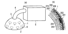
- FIG. 1 (a) is a schematic diagram which shows the general view of the sensor part of the diagnostic apparatus which concerns on the 1st Embodiment of this invention.
- FIG. 1B is a cross-sectional view illustrating the structure of the probe used in the diagnostic apparatus according to the first embodiment of the present invention. It is a typical block diagram explaining the structure of the diagnostic apparatus which concerns on 1st Embodiment. It is sectional drawing explaining the structure of the probe (antenna) used for the diagnostic apparatus which concerns on 1st Embodiment. It is the frequency characteristic of the voltage standing wave ratio which simulated the probe used for the diagnostic apparatus which concerns on 1st Embodiment.
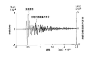
- FIG. 6 is an example illustrating a signal obtained by the artifact removal method illustrated in FIG. 5 and a reception signal of one probe. It is a conceptual diagram explaining the principle of the imaging algorithm used with the conventional ultrasonic diagnostic apparatus for the comparison. It is a block diagram explaining the algorithm of the scattered power calculation used by reconstruction of the diagnostic image of the diagnostic apparatus which concerns on 1st Embodiment.
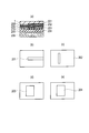
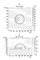
- FIG. 9A is an XY plan view of a simulation model for illustrating the effectiveness of the diagnostic image reconstruction algorithm of the diagnostic apparatus according to the first embodiment.
- FIG. 9B is an XZ plan view of the model shown in FIG.
- FIG. 16 (a) is a real part
- FIG. 16B shows an imaginary part
- FIG. 17A shows the result of image restoration by imaging the complex permittivity distribution shown in FIG. 16
- FIG. 17A shows the real part
- FIG. 17B shows the imaginary part
- FIG. 18A is a diagram for explaining the effectiveness of hybrid imaging according to the third embodiment.
- FIG. 18A shows the real part of the true complex permittivity distribution of the imaging target
- FIG. 18B is the imaginary number thereof. Indicates the part.
- FIG. 18A shows the real part of the true complex permittivity distribution of the imaging target
- FIG. 18B is the imaginary number thereof. Indicates the part.
- FIG. 19A is a diagram showing a result of image recovery by imaging the complex permittivity distribution shown in FIG. 18 in the hybrid imaging according to the third embodiment.
- FIG. 19A is a real part, and FIG. Indicates an imaginary part.
- the figure which shows object constant distribution in the original measurement object part in order to explain that calculation of object constant distribution (tomographic image) converges according to hybrid imaging concerning a 3rd embodiment.
- FIG. 20A shows the relative permittivity distribution
- FIG. 20B shows the conductivity distribution.
- the reflection from the measurement target site is measured to measure the energy distribution, and the state in which the position of the abnormal cell is specified It is a figure explaining.
- FIG. 19A is a diagram showing a result of image recovery by imaging the complex permittivity distribution shown in FIG. 18 in the hybrid imaging according to the third embodiment.
- FIG. 19A is a real part, and FIG. Indicates an imaginary part.
- FIG. 22A is a diagram showing that a tomographic image can be obtained according to the hybrid imaging according to the third embodiment.
- FIG. 22A shows a ratio obtained by calculation when position information of an abnormal cell is known. The distribution of dielectric constant is shown, and FIG. 22B shows the distribution of conductivity obtained by calculation when the position information of abnormal cells is known.
- FIG. 23A shows that the relative permittivity distribution diverges in the calculation when the position information of the abnormal cell is not known.
- FIG. 23B shows the conductivity distribution. It is a figure which shows that it will diverge. It is sectional drawing explaining the conventional microwave imaging method.
- first to third embodiments of the present invention will be described with reference to the drawings.
- the same or similar parts are denoted by the same or similar reference numerals.
- the drawings are schematic, and the relationship between thickness and planar dimensions, the configuration of the apparatus, and the like are different from the actual ones. Therefore, specific thicknesses and dimensions should be determined in consideration of the following description. Moreover, it is a matter of course that portions having different dimensional relationships and ratios are included between the drawings.
- the following first to third embodiments exemplify apparatuses and methods for embodying the technical idea of the present invention, and the technical idea of the present invention is the component parts. The material, shape, structure, arrangement, etc. are not specified below. The technical idea of the present invention can be variously modified within the technical scope described in the claims.
- the diagnostic device is arranged along a container 1 having a semispherical inner wall surface and an inner wall surface as shown in FIGS.
- a probe array (1, 2) having a plurality of probes 2 made of a material having electrical characteristics of a measurement target site for electrical measurement of the target site, and the entire measurement target site as a probe array (1, 2) ), Fixing the relative position between the measurement target site and the probe array (1, 2) to the skin of the measurement target site in close contact with the inner wall surface,
- Measurement control analysis means 10 is provided for controlling the probe 2 to perform electrical measurement, analyzing data obtained by electrical measurement, and detecting abnormal cells in the measurement target site.
- the container 1 is formed of a resin or the like and has an inner wall formed in a semi-spherical shape.
- each of the plurality of probes 2 is an antenna 2 that irradiates an electromagnetic wave to a measurement target site, and a plurality of antennas 2 are arranged on the inner wall surface of the container 1 and UWB. Radar is configured.
- the antenna 2 is configured using a material having an average dielectric constant and dielectric loss of the imaging region, and is a flat or conformal multilayered antenna.
- the fixing means (3, 4, 5) includes exhaust means (4, 5) connected to an exhaust port 3 provided near the apex of the probe array (1, 2).
- the measurement target part is sucked by the exhaust by the exhaust means (4, 5), and the skin of the measurement target part is brought into close contact with the inner wall surface.
- the exhaust means (4, 5) includes a tubular exhaust pipe 4 connected to the exhaust port 3 and a decompression device 5 such as an aspirator connected to the exhaust pipe 4 to decompress the inner wall side of the probe array (1, 2). It is configurable.
- the plurality of probes 2 transmit and receive electromagnetic waves such as microwaves, and a plurality of input / output cables 6 are drawn from the plurality of probes 2, respectively.
- the outlet of the input / output cable 6 is sealed with resin or the like so that air does not leak.
- the probe array (1, 2) of the diagnostic apparatus according to the first embodiment can be used so as to cover the whole breast as a measurement target site, and screening of initial breast cancer can be performed. Therefore, as the antenna 2 as the probe of the present invention, for example, as shown in FIG. 1B and FIG. 3, a slot-fed stack patch antenna having a four-layer structure can be adopted.
- the antenna 2 has, for example, a dielectric substrate 205 having a thickness of 1.27 mm and a dielectric constant of 10.2, a dielectric layer 205 provided on the dielectric substrate 205, a patch layer 203 on the upper surface, and a patch layer 204 mounted on the lower surface.
- dielectric substrate 210 having a dielectric constant of 2.2
- dielectric substrate 209 having a thickness of 1.92 mm and a dielectric constant of 10.2, having a slot layer 202 mounted on the upper surface thereof
- dielectric substrate 209 A dielectric substrate 208 having a thickness of 0.64 mm and a relative dielectric constant of 10.2 provided on the upper surface and having the stripline layer 201 mounted on the upper surface thereof can be formed.
- the value of permittivity 10.2 is approximately equal to the relative permittivity 9.8 of the adipose tissue of the breast.
- the stripline layer 201 is connected to the input / output cable 6 at the output end via a connector or the like as shown in FIG.
- the stripline layer 201 and the patch layers 203 and 204 are electromagnetically coupled via the slot layer 202.
- the patch layers 203 and 204 have different sizes.
- the antenna 2 is embedded in the inner wall of the container 1 so as to expose the dielectric substrate 205, and is aligned in a state of being in close contact with the skin on the surface of the measurement target region (breast) 206. When configured in this manner, the antenna is equivalent electromagnetically in the breast, and the electromagnetic waves efficiently enter the breast tissue.
- FIG. 4 shows the voltage standing wave ratio (VSWR) of the antenna 2 calculated under the use conditions described with reference to FIG. As shown in FIG. 4, it can be confirmed that VSWR ⁇ 2.5 is realized at a frequency of 4 to 10 GHz.
- VSWR voltage standing wave ratio
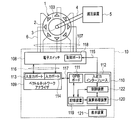
- the measurement control analysis unit 10 controls the driving of the plurality of antennas 2 via the electronic switch 108 that controls the driving of the plurality of antennas 2 and the electronic switch 108.
- a vector network analyzer 109 for analyzing the signal a control arithmetic device 110 for controlling the switching operation of the electronic switch 108, and a display device 121 connected to the control arithmetic device 110 for displaying measurement conditions, measurement results, and the like.
- a personal computer (PC), various microprocessors, or the like can be used as the control arithmetic unit 110.
- the electronic switch 108 includes a control port 118, and the control port 118 and the control arithmetic device 110 are connected via the cable 115.
- the electronic switch 108 is further connected to the probe array (1, 2) via the coaxial cable 107.
- the coaxial cable 107 is formed from a plurality of input / output cables 6 drawn from a plurality of antennas 2.
- the vector network analyzer 109 includes an input / output port 113 and an input port 114, and the input / output port 113 and the input port 114 are connected to the electronic switch 108 via a coaxial cable 116, respectively.
- the control arithmetic unit 110 includes a GPIB board 111 for interconnection with the vector network analyzer 109 via the GPIB cable 117, an input / output interface 112 connected to the electronic switch 108 via the cable 115, various parameters related to measurement, , A storage device 119 for storing measurement results, an arithmetic processing unit 120 for performing various calculations necessary for measurement and imaging, and a control for controlling driving of each unit of the control arithmetic unit 110, the electronic switch 108, and the vector network analyzer 109 A device 122 is provided.
- the probe array (1, 2) is placed on the measurement target site (breast) 206 so that the position of the exhaust port 3 matches the position of the nipple of the subject, and the pressure is reduced. It is used after being exhausted by the device 5.
- the decompression device 5 sucks air between the probe array (1, 2) and the gap between the measurement target region (breast) 206, so that the skin of the measurement target region (breast) 206 becomes the probe array (1, 2).
- the measurement target region (breast) 206 is formed in a hemispherical shape and also in close contact with the plurality of antennas 2.
- the positional relationship between the plurality of antennas 2 and the skin surface of the region to be measured (breast) 206 is constant, and the averaging process described with reference to FIG. Can be captured clearly. Since the shape of the part to be measured (breast) 206 is mechanically molded, it is not necessary to hang down and to hang down the part to be measured (breast) 206, and the examination can be performed while standing. Further, in order to cope with individual differences in the size of the measurement target region (breast) 206, a plurality of hemispherical probe arrays (1, 2) having different radii are prepared in advance. Select according to the size of the.
- the diagnostic apparatus it is not necessary to modify the reception response according to the measurement distance, and the system for measuring the measurement target region (breast) and the distance between the probes is eliminated.
- the hemispherical container 1 having different radii is used by adapting to individual differences, so that the breast is not drooped, so that it can be applied to a subject having a small breast. it can.
- an unpleasant sensation due to the suction of the measurement target region (breast) 206 can be reduced.
- Patent Documents 2 and 3 since the transmission / reception sensor is integrated with the mold, there is an advantageous effect that the subject's movement is free.
- the control device 122 of the control arithmetic device 110 receives control signals for sequentially connecting the input / output port 113 and the input port 114 of the network analyzer 109 and two probes selected from the plurality of antennas 2 as follows. To the electronic switch 108.
- the control arithmetic unit 110 is connected to the electronic switch 108, the input / output port 113 of the vector network analyzer 109 to the first antenna 2-1 of the probe array (1, 2), and the input port 114 to 2 of the probe array (1, 2). Command to connect to the second antenna 2-2.
- the vector network analyzer 109 outputs a sweep signal in a predetermined frequency range from the input / output port 113 and transmits it from the antenna 2-1.
- Vector network analyzer 109 receives a reception signal from the antenna 2-2, to measure the transmission loss between the antenna 2-1 to the antenna 2-2 A 12 (f) and the transmission phase P 12 (f).
- the transmission loss and the transmission phase are responses related to the frequency f obtained by sweeping the frequency.
- the measurement result is output to the control arithmetic device 110 via the GPIB cable 117 and stored in the storage device 119 of the control arithmetic device 110.
- the control arithmetic unit 110 issues a command to the electronic switch 108 to connect the input / output port 113 of the vector network analyzer 109 to the first antenna 2-1 and the input port 114 to the third antenna 2-3.
- the vector network analyzer 109 measures the transmission loss A 13 (f) and the transmission phase P 13 (f) between the antennas 2-1 to 2-3.
- the measurement result is sent to the control arithmetic device 110 via the GPIB cable 117 and stored in the storage device 119 of the control arithmetic device 110.
- the above operation is repeated for the antenna 2-1 on the transmission side up to the antenna 2-N.
- control arithmetic unit 110 issues a command to the electronic switch 108 to connect the input / output port 113 of the vector network analyzer 109 to the second antenna 2-2 and the input port 114 to the third antenna 2-3.
- the vector network analyzer 109 measures the transmission loss A 23 (f) and the transmission phase P 23 (f) between the antenna 2-2 and the antenna 2-3.
- the measurement result is sent to the control arithmetic device 110 via the GPIB cable 117 and stored in the storage device 119 of the control arithmetic device 110.
- the control arithmetic unit 110 issues a command to the electronic switch 108 to connect the input / output port 113 of the vector network analyzer 109 to the second antenna 2-2 and the input port 114 to the fourth antenna 2-4.
- the vector network analyzer 109 measures the transmission loss A 24 (f) and the transmission phase P 24 (f) between the antenna 2-2 and the antenna 2-4.
- the measurement result is sent to the control arithmetic device 110 via the GPIB cable 117 and stored in the storage device 119 of the control arithmetic device 110. The above operation is repeated until reception for the antenna 2-N.
- control arithmetic unit 110 is connected to the electronic switch 108, the input / output port 113 of the vector network analyzer 109 is connected to the (N-1) th antenna 2- (N-1) of the probe array (1, 2), A command is issued to connect the input port 114 to the Nth antenna 2-N of the probe array (1, 2), and the vector network analyzer transmits a transmission loss 2A N ⁇ between the antenna 2- (N ⁇ 1) and the antenna 2-N. 1 N (f) and transmission phase P N-1 N (f) are measured and repeated until stored in the storage device 119 of the control arithmetic unit 110.
- the measurement data is sent to the arithmetic processing unit 120 and the scattered electric field distribution in the imaging range is calculated.
- the arithmetic processing unit 120 displays the calculation result on the display device 121 as a diagnostic image.
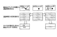
- the imaging algorithm is composed of two processes: pre-processing for removing artifacts such as skin reflection, and frequency space beam forming for obtaining scattered power for each pixel in the imaging region.
- FIG. 7 is an explanatory diagram showing the principle of the DAS algorithm.
- the DAS algorithm corrects and adds the reception response times of a plurality of probes at different positions by a propagation delay corresponding to the distance between the transmission / reception probe and an arbitrary pixel in the imaging region and the transmission / reception probe.
- the time of the scattered response signal from each probe is aligned, and a large response is obtained by adding them. If there is no tumor at that point, the time of the scattered response signal is not aligned, and even if added, a large response cannot be obtained.
- Non-Patent Document 1 is a technique for directivity synthesis in the frequency-space region using weights with an array gain of 1 at a specified pixel in consideration of the frequency characteristics of the medium.
- Non-patent document 1 assumes that the probe is used in a monostatic radar that performs transmission and reception with a probe at the same position, and does not consider application in a multistatic radar. In the present invention, this is modified so that it can be applied to a multi-static radar and imaging is performed. Described below is the process MIST with reference to FIG. 8 showing the processing procedure at any position r 0 of the imaging region.
- the control device 122 outputs a measurement start signal to the vector network analyzer 109 and receives a measurement end signal from the vector network analyzer 109, and then reads out the measurement results of transmission loss and transmission transfer.
- the read transmission loss and transmission transfer are converted into a complex signal in the arithmetic processing unit 120, and then subjected to inverse Fourier transform to be a time domain signal.
- a signal transmitted from the i-th probe and received by the j-th probe is assumed to be x ij [n] (n is a discrete time).
- ⁇ ij (r 0 ) is a propagation delay in units of sample interval T s at r 0 . or,
- the maximum propagation delay in the imaging area is the maximum propagation delay in the imaging area.
- step S102 applying the following window function to remove clutter that precede n a:
- step S103 this signal is converted into the frequency domain, and in step S104, beam forming is performed in the frequency-space domain.
- the weight W ij [l] of a beamformer having an amplitude response of 1 and a linear phase response is expressed by the following equation:
- ⁇ l is the l-th frequency
- I [ ⁇ l ] is the spectrum of the transmitted signal
- Is the response obtained by removing the phase shift related to the propagation delay from the multistatic radar response at the position of r 0 of the l-th frequency of the i-th probe and the j-th probe
- M is the number of discrete frequencies.
- step S105 the output of the beamformer in the frequency domain is obtained.
- the output in the frequency domain is expressed as:
- X ij (r 0 , ⁇ i ) is a reception response in the frequency domain at the position of r 0 of the l-th frequency of the i-th probe and the j-th probe.
- this is Fourier transformed back to the time domain signal z [n]
- step S107 the main window lobe portion of the time response is extracted by applying the following window function to calculate the scattered power:
- step S108 after applying the window function, the energy is calculated as the scattered power at r 0 :
- 9 to 11 show simulation models.
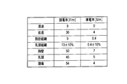
- the imaging target is composed of skin, adipose tissue, mammary gland tissue, chest wall, nipple, and tumor.
- the dielectric constant and conductivity of each component are also shown in FIG.
- the probe places a 12 ⁇ 6 element 602 on a hemispherical surface 601 having a radius of 4 cm.
- the radius of the tumor is 3 mm and the skin thickness is 2 mm.
- the size of the pixel is a cube with one side of 1 mm.
- FIG. 12 shows an imaging simulation result according to the present invention
- FIG. 13 shows a non-patent document 2
- FIG. 14 shows a non-patent document 1 algorithm.
- the algorithm of the present invention captures the tumor most clearly and has few false images.
- the calculation time per pixel is 21 seconds for the algorithm of the present invention, 186 seconds for the algorithm of Non-Patent Document 2, and 0. 0 for the algorithm of Non-Patent Document 3.
- the amount of calculation is larger than that of Non-Patent Document 1, but it is within a practically acceptable range.
- the antenna 2 as a probe is aligned with the skin of the measurement target region 206 in close contact with each other, the antenna 2 is radiated from the antenna 2.
- the electromagnetic wave efficiently enters the measurement target region (breast) 206, and it is not necessary to immerse the antenna 2 and the measurement target region (breast) 206 in the matching medium. Further, it is possible to obtain an advantageous effect that there is no discomfort in immersing the measurement target portion (breast) 206 in the alignment medium, and there is no surrounding contamination due to splashes of the alignment medium.
- UWB radar is a kind of impulse radar and has excellent distance resolution.
- the pulse width is extremely narrow, and it is difficult to directly sample with an AD converter for signal processing. Therefore, in the diagnostic apparatus according to the first embodiment, Fourier transform is used to convert time domain impulses into wideband frequency domain signals.
- Impulse transmission / reception is equivalent to frequency sweep signal transmission / reception. Since the vector network analyzer 109 can measure the transmission / reflection characteristics while sweeping the frequency, it can be used as a transceiver. Since the vector network analyzer 109 is a general-purpose measuring instrument, it has an advantageous effect that it can be easily obtained and has high reliability.
- the scattering response is obtained by reflection measurement of the vector network analyzer 109.
- the transmitting and receiving antennas 2 are separated, and the scattering response is obtained by transmission measurement.
- a multi-static radar having a plurality of receiving antennas 2 installed at different locations can obtain a lot of scattering response information. Furthermore, more scattered response information can be obtained by changing the position of the transmitting antenna 2 and receiving the signal.
- the electronic switch is provided for time division transmission / reception.
- N C 2 N (N ⁇ 1) / 2 multi-static radar response (transmission loss and This is realized by applying frequency / space beam forming to (transmission phase), and does not include a parameter that is not uniquely determined, and the reliability of the imaging result is high. Therefore, the diagnostic device according to the first embodiment has an advantageous effect that the amount of calculation is small and a large number of diagnoses can be endured.
- the probe array is not limited to a multi-layer planar or conformal antenna as described in the first embodiment.
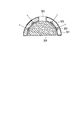
- the probe array (301, 302) according to the second embodiment of the present invention is molded from a semi-spherical resin as in the first embodiment.
- a plurality of probes (antennas) 302 are arranged in a cavity surrounded by the inner wall surface and the outer wall surface, and the matching medium 305 having the same dielectric constant and conductivity as the fat layer of the breast as the measurement target region 304 is filled. This is different from the first embodiment.
- the probe array (301, 302) includes a plurality of antennas (probes) 302 arranged in a cavity surrounded by a container 301 having a semicircular inner wall and an outer wall facing the inner wall. And a matching medium 305 filled in the cavity.
- the diagnostic device according to the second embodiment also covers the entire region to be measured with the probe array (301, 302) in the same manner as the diagnostic device according to the first embodiment.
- Fixing means (see reference numerals 3, 4 and 5 in FIG. 1) for fixing the relative position between the measurement target site and the probe array (301, 302), and the skin of the measurement target site in close contact with the inner wall surface;
- a measurement control analysis means (see reference numeral 10 in FIG. 2) that controls the plurality of probes 302 to perform electrical measurement, analyzes data obtained by electrical measurement, and detects abnormal cells in the measurement target site.
- the container 301 of the diagnostic device according to the second embodiment is provided with an exhaust port 303 in the vicinity of the apex.
- the fixing means includes the exhaust port 303. From the inside, the inner wall side of the container 301 can be exhausted.
- the container 301 is placed so as to cover the entire region to be measured (breast) 304 so that the exhaust port 303 of the container 301 and the position of the subject's nipple are aligned, and the exhaust is exhausted by a decompression device (aspirator).
- the skin of the breast 304 is brought into close contact with the inner wall of the container 301 by the exhaust, and the breast 304 is formed in a hemispherical shape.
- a plurality of antennas 302 having no planar or conformal structure can be used. Since the matching medium 305 having the same dielectric constant and conductivity as the fat layer of the breast 304 is used, the amount of electromagnetic waves transmitted into the tissue is increased.
- a plurality of antennas 302 are formed by exhausting the space between the probe array (301, 302) and the breast 304 using the fixing means, and fixing the inner wall surface of the probe array (301, 302) and the breast 304 in close contact with each other. And the positional relationship between the breast 304 and the skin surface are constant.
- the averaging process described with reference to FIG. 5 can remove a large reflection from the skin, and has an advantageous effect that the response from the tumor can be clearly captured. Can do.
- the shape of the breast 304 is mechanically molded, there is no need to take the prone posture and to hang down the breast 304 even if the alignment medium is used, and there is an advantageous effect that the examination can be performed while standing. be able to.
- a plurality of probe arrays (301, 302) having different sizes are prepared in advance, and selected and used according to the size of the breast 304 is the same as in the first embodiment. It is the same.
- the technique for identifying a lesion portion by frequency-space beam formation by multistatic radar has been described.
- the measurement target After detecting an abnormal cell (lesion part) in the region a tomography unit that performs tomography only around the abnormal cell part (lesion part) is further provided, and hybrid imaging can be performed by a hybrid imaging algorithm.
- the complex permittivity (relative permittivity and conductivity) distribution of the imaging area can be estimated with higher accuracy.
- the tomography means of the diagnostic apparatus according to the embodiment it is possible to use known techniques as described in Non-Patent Document 3 and Patent Document 1.
- the combination of transmission and reception of the probe 2 is changed as appropriate, the propagation model is inversely calculated from the received signal, and the complex dielectric constant (relative dielectric constant and A means for estimating the (conductivity) distribution (tomographic image) may be configured.
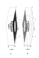
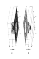
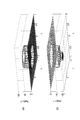
- 16 and 17 are diagrams showing imaging results obtained by conventional tomography for comparison, FIG. 16 is a true complex permittivity distribution in a certain plane, and FIG. 17 is a result of image restoration. In conventional tomographic imaging, it can be seen that the result of image restoration is not the correct complex permittivity.
- FIG. 18 and 19 are diagrams showing the results of tomography after specifying the position of abnormal cells (lesion portions) and giving preliminary knowledge in the hybrid imaging according to the third embodiment.
- FIG. 18 shows the true complex permittivity distribution
- FIG. 19 shows the result of image restoration. According to the hybrid imaging according to the third embodiment, it can be seen that the result of image restoration is a correct complex permittivity.
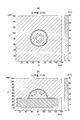
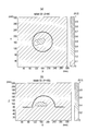
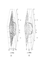
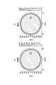
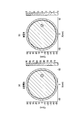
- the data diverges when the object constant distribution (tomographic image) is obtained without specifying the position of the abnormal cell (lesion part), but the position information of the abnormal cell (lesion part) is known. It is a figure which shows that if a body constant distribution (tomographic image) is calculated in a state, it will converge and a tomographic image can be calculated
- FIG. 20 is a diagram showing an object constant distribution in the original measurement target part
- FIG. 20 (a) shows a distribution of relative permittivity
- FIG. 20 (b) shows a distribution of conductivity
- FIG. 21 shows the frequency-space beam formation by the multistatic radar described in the first or second embodiment, the reflection from the measurement target site is measured, the energy distribution is measured, and abnormal cells (lesions) It is a figure which shows having specified the position of (part).
- the object constant distribution tomographic image
- 22A shows the distribution of relative permittivity obtained by calculation when the position information of the abnormal cell (lesion portion) is known
- FIG. 22B shows the position of the abnormal cell (lesion portion). The distribution of conductivity obtained by calculation when the information is known is shown.
- FIG. 23 (a) shows that the data of the relative permittivity distribution to be obtained by calculation when the position information of the abnormal cell (lesion part) is not known diverges, and FIG. This indicates that the conductivity distribution data to be calculated is diverged when the position information of the cell (lesion portion) is not known.
- the hybrid imaging according to the third embodiment since the imaging device and the imaging sensor can be shared, the complex permittivity distribution of the imaging target is obtained without taking data again. Further, the hybrid imaging according to the third embodiment has an advantage that it can be applied to the elimination of false images (artifacts) generated by the imaging algorithm.
- the algorithm based on the measurement results of transmission loss and transmission phase between different probes has been described, but the reflection loss and reflection phase transmitted and received by the same probe are also measured, the transmission loss,
- the directivity may be combined with the measurement result of the transmission phase.
- the following operations are added to the operations of the electronic switch, the vector network analyzer, and the control arithmetic unit in addition to the above operations.
- the control arithmetic unit issues an instruction to the electronic switch to connect the input / output port of the vector network analyzer to the first probe of the container.
- the vector network analyzer When the connection operation with the electronic switch is completed, the vector network analyzer outputs a sweep signal in a predetermined frequency range from the output port, receives the reflected signal from the first probe, and returns the reflection loss of the first probe. A 11 (f) and the reflection phase P 11 (f) are measured. The measurement result is stored in the storage device of the control arithmetic device. Next, the control arithmetic unit issues a command to the electronic switch to connect the input / output port of the vector network analyzer to the second probe of the container. Once the connection operation in the electronic switch is complete, the vector network analyzer measures the second reflection loss of the probe A 22 (f) and the reflection phase P 22 (f). The measurement result is stored in the storage device of the PC. The above operation is repeated until the Nth probe. The above-described averaging process is applied to the artifact removal, and the calculation of the scattered power at the pixel is executed by removing the condition of i ⁇ j in the equations (3) to (5).
- control arithmetic device 110 may control the operation of the decompression device 5 so that the decompression and the measurement operation are linked.
- the present invention naturally includes various embodiments not described herein. Accordingly, the technical scope of the present invention is defined only by the invention specifying matters according to the scope of claims reasonable from the above description.
- the diagnostic apparatus and probe array according to the present invention are used in the field of diagnosis of abnormal cells such as early breast cancer which is safe, reliable, comfortable and low cost.
Landscapes
- Health & Medical Sciences (AREA)
- Life Sciences & Earth Sciences (AREA)
- Surgery (AREA)
- Nuclear Medicine, Radiotherapy & Molecular Imaging (AREA)
- Medical Informatics (AREA)
- General Health & Medical Sciences (AREA)
- Veterinary Medicine (AREA)
- Engineering & Computer Science (AREA)
- Biomedical Technology (AREA)
- Heart & Thoracic Surgery (AREA)
- Public Health (AREA)
- Molecular Biology (AREA)
- Animal Behavior & Ethology (AREA)
- Pathology (AREA)
- Radiology & Medical Imaging (AREA)
- Physics & Mathematics (AREA)
- Biophysics (AREA)
- Neurosurgery (AREA)
- Oral & Maxillofacial Surgery (AREA)
- Oncology (AREA)
- Ultra Sonic Daignosis Equipment (AREA)
Abstract
Priority Applications (2)
| Application Number | Priority Date | Filing Date | Title |
|---|---|---|---|
| JP2011518575A JP5605783B2 (ja) | 2009-06-10 | 2010-06-10 | 診断装置 |
| US13/377,264 US20120083683A1 (en) | 2009-06-10 | 2010-06-10 | Diagnosis apparatus |
Applications Claiming Priority (2)
| Application Number | Priority Date | Filing Date | Title |
|---|---|---|---|
| JP2009-139664 | 2009-06-10 | ||
| JP2009139664 | 2009-06-10 |
Publications (1)
| Publication Number | Publication Date |
|---|---|
| WO2010143691A1 true WO2010143691A1 (fr) | 2010-12-16 |
Family
ID=43308946
Family Applications (1)
| Application Number | Title | Priority Date | Filing Date |
|---|---|---|---|
| PCT/JP2010/059855 Ceased WO2010143691A1 (fr) | 2009-06-10 | 2010-06-10 | Appareil de diagnostic |
Country Status (3)
| Country | Link |
|---|---|
| US (1) | US20120083683A1 (fr) |
| JP (1) | JP5605783B2 (fr) |
| WO (1) | WO2010143691A1 (fr) |
Cited By (12)
| Publication number | Priority date | Publication date | Assignee | Title |
|---|---|---|---|---|
| JP2011505173A (ja) * | 2007-11-05 | 2011-02-24 | マイクリーマ リミテッド | サーチボリュームの内容物を測定する方法および装置 |
| JP2013113603A (ja) * | 2011-11-25 | 2013-06-10 | Kyushu Univ | マイクロ波イメージングシステム及びイメージング処理方法 |
| JPWO2015136936A1 (ja) * | 2014-03-12 | 2017-04-06 | 国立大学法人神戸大学 | 散乱トモグラフィ方法および散乱トモグラフィ装置 |
| JPWO2017057524A1 (ja) * | 2015-09-29 | 2018-08-02 | 国立大学法人神戸大学 | 画像化方法および画像化装置 |
| JP2018529979A (ja) * | 2015-08-04 | 2018-10-11 | ミクリマ リミテッド | 対象体の内部構造を探査するシステムにおいてフィット状態を評価するための方法、装置、およびコンピュータ可読媒体 |
| JP2019520876A (ja) * | 2016-05-17 | 2019-07-25 | ミクリマ リミテッド | 医用画像化システムおよび方法 |
| JP2019527112A (ja) * | 2016-07-29 | 2019-09-26 | ミクリマ リミテッド | 医用撮像システム |
| JP2019531773A (ja) * | 2016-08-12 | 2019-11-07 | ミクリマ リミテッド | 医用撮像システムおよび方法 |
| JP2020503080A (ja) * | 2016-10-27 | 2020-01-30 | ミクリマ リミテッド | マイクロ波及び超音波画像を組み合わせたシステム及び方法 |
| JP2020513886A (ja) * | 2016-12-19 | 2020-05-21 | ミクリマ リミテッド | 医用画像処理システムおよび方法 |
| JP2021536328A (ja) * | 2018-09-04 | 2021-12-27 | エムビジョン・メディカル・デバイシーズ・リミテッドEMvision Medical Devices Ltd | 医療用イメージングのための装置及び処理 |
| JP2022525146A (ja) * | 2019-03-14 | 2022-05-11 | エムビジョン・メディカル・デバイシーズ・リミテッド | ハイブリッド医療イメージングプローブ、装置及び方法 |
Families Citing this family (14)
| Publication number | Priority date | Publication date | Assignee | Title |
|---|---|---|---|---|
| US9724010B2 (en) | 2010-07-08 | 2017-08-08 | Emtensor Gmbh | Systems and methods of 4D electromagnetic tomographic (EMT) differential (dynamic) fused imaging |
| CN102764120A (zh) * | 2012-08-17 | 2012-11-07 | 思澜科技(成都)有限公司 | 一种用于乳房成像的电极罩 |
| CN102894975B (zh) * | 2012-10-28 | 2015-01-07 | 思澜科技(成都)有限公司 | 一种用于乳房成像的电极罩 |
| WO2014081992A2 (fr) | 2012-11-21 | 2014-05-30 | Emtensor Gmbh | Solutions de tomographie électromagnétique pour balayage de tête |
| WO2014141268A1 (fr) * | 2013-03-14 | 2014-09-18 | Vayyar Imaging Ltd. | Imagerie par micro-ondes résistante au fouillis d'échos de fond et de la peau |
| US9072449B2 (en) | 2013-03-15 | 2015-07-07 | Emtensor Gmbh | Wearable/man-portable electromagnetic tomographic imaging |
| US20140275944A1 (en) | 2013-03-15 | 2014-09-18 | Emtensor Gmbh | Handheld electromagnetic field-based bio-sensing and bio-imaging system |
| JP6278770B2 (ja) * | 2014-03-19 | 2018-02-14 | キヤノン株式会社 | 被検体情報取得装置 |
| CN108366771B (zh) | 2015-10-16 | 2021-11-02 | 埃姆丹索有限公司 | 电磁干涉图案识别层析成像 |
| CA3044844A1 (fr) | 2016-11-23 | 2018-05-31 | Emtensor Gmbh | Utilisation d'un champ electromagnetique destine a une imagerie tomographique d'une tete |
| US10983209B2 (en) * | 2017-04-12 | 2021-04-20 | Ellumen, Inc. | Accurate signal compensations for UWB radar imaging in dispersive medium |
| JP2024051235A (ja) * | 2022-09-30 | 2024-04-11 | 学校法人 愛知医科大学 | 診断装置、画像再構成処理の実行方法及び診断プログラム |
| JP2026500757A (ja) * | 2022-12-26 | 2026-01-08 | ブレスト キャンサー イーエム システムズ(ビーシーイーエムエス) エルティーディー | 乳がんの早期発見用の超広帯域かつ多角度のマイクロ波イメージング |
| US20250057434A1 (en) * | 2023-08-18 | 2025-02-20 | Choon Sae Lee | Microwave Imaging for Breast Cancer Detection |
Citations (7)
| Publication number | Priority date | Publication date | Assignee | Title |
|---|---|---|---|---|
| JPS62161343A (ja) * | 1985-11-07 | 1987-07-17 | エム/エイ−コム・インコ−ポレ−テツド | 複式アンテナ胸部スクリ−ニング装置 |
| JPH11146874A (ja) * | 1997-11-18 | 1999-06-02 | Shimadzu Corp | X線ct装置 |
| JP2008500087A (ja) * | 2004-05-26 | 2008-01-10 | メディカル・デバイス・イノベーションズ・リミテッド | 組織検知およびアブレーション機器ならびにチューナを作動させる機器および方法 |
| JP2008512175A (ja) * | 2004-09-10 | 2008-04-24 | インダストリアル・リサーチ・リミテッド | イメージングシステム |
| JP2008530546A (ja) * | 2005-02-09 | 2008-08-07 | ザ・ユニヴァーシティ・オブ・ブリストル | 物体の内部構造を測定する方法および装置 |
| JP2008220638A (ja) * | 2007-03-13 | 2008-09-25 | General Electric Co <Ge> | 乳房不動化装置及び乳房撮像方法 |
| JP2009508539A (ja) * | 2005-08-04 | 2009-03-05 | デューン メディカル デヴァイシズ リミテッド | 有効なセンサ対組織接触を持つ組織特性化プローブ |
Family Cites Families (3)
| Publication number | Priority date | Publication date | Assignee | Title |
|---|---|---|---|---|
| US7742796B2 (en) * | 2005-10-25 | 2010-06-22 | General Electric Company | Breast immobilization device and method of imaging the breast |
| US7597104B2 (en) * | 2007-03-23 | 2009-10-06 | Zheng Mike Q | Method and device for immobilization of the human breast in a prone position for radiotherapy |
| US8089417B2 (en) * | 2007-06-01 | 2012-01-03 | The Royal Institution For The Advancement Of Learning/Mcgill University | Microwave scanning system and miniaturized microwave antenna |
-
2010
- 2010-06-10 WO PCT/JP2010/059855 patent/WO2010143691A1/fr not_active Ceased
- 2010-06-10 JP JP2011518575A patent/JP5605783B2/ja not_active Expired - Fee Related
- 2010-06-10 US US13/377,264 patent/US20120083683A1/en not_active Abandoned
Patent Citations (7)
| Publication number | Priority date | Publication date | Assignee | Title |
|---|---|---|---|---|
| JPS62161343A (ja) * | 1985-11-07 | 1987-07-17 | エム/エイ−コム・インコ−ポレ−テツド | 複式アンテナ胸部スクリ−ニング装置 |
| JPH11146874A (ja) * | 1997-11-18 | 1999-06-02 | Shimadzu Corp | X線ct装置 |
| JP2008500087A (ja) * | 2004-05-26 | 2008-01-10 | メディカル・デバイス・イノベーションズ・リミテッド | 組織検知およびアブレーション機器ならびにチューナを作動させる機器および方法 |
| JP2008512175A (ja) * | 2004-09-10 | 2008-04-24 | インダストリアル・リサーチ・リミテッド | イメージングシステム |
| JP2008530546A (ja) * | 2005-02-09 | 2008-08-07 | ザ・ユニヴァーシティ・オブ・ブリストル | 物体の内部構造を測定する方法および装置 |
| JP2009508539A (ja) * | 2005-08-04 | 2009-03-05 | デューン メディカル デヴァイシズ リミテッド | 有効なセンサ対組織接触を持つ組織特性化プローブ |
| JP2008220638A (ja) * | 2007-03-13 | 2008-09-25 | General Electric Co <Ge> | 乳房不動化装置及び乳房撮像方法 |
Non-Patent Citations (2)
Cited By (18)
| Publication number | Priority date | Publication date | Assignee | Title |
|---|---|---|---|---|
| JP2011505173A (ja) * | 2007-11-05 | 2011-02-24 | マイクリーマ リミテッド | サーチボリュームの内容物を測定する方法および装置 |
| JP2013113603A (ja) * | 2011-11-25 | 2013-06-10 | Kyushu Univ | マイクロ波イメージングシステム及びイメージング処理方法 |
| JPWO2015136936A1 (ja) * | 2014-03-12 | 2017-04-06 | 国立大学法人神戸大学 | 散乱トモグラフィ方法および散乱トモグラフィ装置 |
| US10101282B2 (en) | 2014-03-12 | 2018-10-16 | National University Corporation Kobe University | Scattering tomography method and scattering tomography device |
| JP2018529979A (ja) * | 2015-08-04 | 2018-10-11 | ミクリマ リミテッド | 対象体の内部構造を探査するシステムにおいてフィット状態を評価するための方法、装置、およびコンピュータ可読媒体 |
| JPWO2017057524A1 (ja) * | 2015-09-29 | 2018-08-02 | 国立大学法人神戸大学 | 画像化方法および画像化装置 |
| US10624556B2 (en) | 2016-05-17 | 2020-04-21 | Micrima Limited | Medical imaging system and method |
| JP2019520876A (ja) * | 2016-05-17 | 2019-07-25 | ミクリマ リミテッド | 医用画像化システムおよび方法 |
| JP2019527112A (ja) * | 2016-07-29 | 2019-09-26 | ミクリマ リミテッド | 医用撮像システム |
| US11457831B2 (en) | 2016-07-29 | 2022-10-04 | Micrima Limited | Medical imaging system and method |
| JP2019531773A (ja) * | 2016-08-12 | 2019-11-07 | ミクリマ リミテッド | 医用撮像システムおよび方法 |
| JP7134164B2 (ja) | 2016-08-12 | 2022-09-09 | ミクリマ リミテッド | 医用撮像システムおよび方法 |
| JP2020503080A (ja) * | 2016-10-27 | 2020-01-30 | ミクリマ リミテッド | マイクロ波及び超音波画像を組み合わせたシステム及び方法 |
| JP2020513886A (ja) * | 2016-12-19 | 2020-05-21 | ミクリマ リミテッド | 医用画像処理システムおよび方法 |
| JP7090086B2 (ja) | 2016-12-19 | 2022-06-23 | ミクリマ リミテッド | 医用画像処理システムおよび方法 |
| JP2021536328A (ja) * | 2018-09-04 | 2021-12-27 | エムビジョン・メディカル・デバイシーズ・リミテッドEMvision Medical Devices Ltd | 医療用イメージングのための装置及び処理 |
| JP7397067B2 (ja) | 2018-09-04 | 2023-12-12 | エムビジョン・メディカル・デバイシーズ・リミテッド | 医療用イメージングのための装置及び処理 |
| JP2022525146A (ja) * | 2019-03-14 | 2022-05-11 | エムビジョン・メディカル・デバイシーズ・リミテッド | ハイブリッド医療イメージングプローブ、装置及び方法 |
Also Published As
| Publication number | Publication date |
|---|---|
| JP5605783B2 (ja) | 2014-10-15 |
| JPWO2010143691A1 (ja) | 2012-11-29 |
| US20120083683A1 (en) | 2012-04-05 |
Similar Documents
| Publication | Publication Date | Title |
|---|---|---|
| JP5605783B2 (ja) | 診断装置 | |
| Felicio et al. | Microwave breast imaging using a dry setup | |
| Li et al. | Microwave imaging via space-time beamforming: Experimental investigation of tumor detection in multilayer breast phantoms | |
| Yun et al. | Compact antenna for radar-based breast cancer detection | |
| CA3111578A1 (fr) | Appareil et procede d'imagerie medicale | |
| US9504404B1 (en) | Antipodal vivaldi antenna array for biomedical imaging | |
| US20060241409A1 (en) | Time domain inverse scattering techniques for use in microwave imaging | |
| Khalesi et al. | Free-space operating microwave imaging device for bone lesion detection: A phantom investigation | |
| CN111031895A (zh) | 用于估计对象的脂肪含量分数的方法 | |
| CN109199381B (zh) | 一种全息微波弹性成像系统及其成像方法 | |
| EP1996078A1 (fr) | Système d'imagerie | |
| JP2008512175A (ja) | イメージングシステム | |
| JP2014198067A (ja) | 診断装置 | |
| WO2011100343A2 (fr) | Système et procédé pour la collecte et l'utilisation de données de résonance magnétique et données de micro-onde permettant d'identifier des limites d'intérêt | |
| US20070293752A1 (en) | Synthetic Focusing Method | |
| EP1788946A1 (fr) | Systeme d'imagerie | |
| Nguyen et al. | High frequency breast imaging: Experimental analysis of tissue phantoms | |
| Mahfuz et al. | Microstrip patch antennas for breast tumor/cancer cell detection–challenges, designs, and future opportunities: A review | |
| Sultan et al. | Handheld electromagnetic scanner for deep vein thrombosis detection and monitoring | |
| Asok et al. | Breast Tumor Detection using Multi-static Microwave Imaging with Vivaldi Antennas utilizing a Novel Preprocessing stage in DAS Algorithm | |
| CN116421164A (zh) | 超宽带太赫兹成像系统及成像方法 | |
| Zamani et al. | Frequency domain method for early stage detection of congestive heart failure | |
| Maffongelli et al. | Design and experimental test of a microwave system for quantitative biomedical imaging | |
| Zamani et al. | Three-dimensional electromagnetic torso imaging using reconfigurable antennas | |
| Gangwar et al. | Pediatric Corpulence Assessment Using Ultra-Wideband Radar Imaging System: A Novel Approach in Tissue Characterization |
Legal Events
| Date | Code | Title | Description |
|---|---|---|---|
| 121 | Ep: the epo has been informed by wipo that ep was designated in this application |
Ref document number: 10786222 Country of ref document: EP Kind code of ref document: A1 |
|
| DPE1 | Request for preliminary examination filed after expiration of 19th month from priority date (pct application filed from 20040101) | ||
| WWE | Wipo information: entry into national phase |
Ref document number: 2011518575 Country of ref document: JP |
|
| WWE | Wipo information: entry into national phase |
Ref document number: 13377264 Country of ref document: US |
|
| NENP | Non-entry into the national phase |
Ref country code: DE |
|
| 122 | Ep: pct application non-entry in european phase |
Ref document number: 10786222 Country of ref document: EP Kind code of ref document: A1 |