WO2010143925A4 - 광대역 무선 접속시스템에서 효율적인 캐리어 관리 방법 - Google Patents
광대역 무선 접속시스템에서 효율적인 캐리어 관리 방법 Download PDFInfo
- Publication number
- WO2010143925A4 WO2010143925A4 PCT/KR2010/003807 KR2010003807W WO2010143925A4 WO 2010143925 A4 WO2010143925 A4 WO 2010143925A4 KR 2010003807 W KR2010003807 W KR 2010003807W WO 2010143925 A4 WO2010143925 A4 WO 2010143925A4
- Authority
- WO
- WIPO (PCT)
- Prior art keywords
- carrier
- message
- base station
- terminal
- activation
- Prior art date
- Legal status (The legal status is an assumption and is not a legal conclusion. Google has not performed a legal analysis and makes no representation as to the accuracy of the status listed.)
- Ceased
Links
Images


Classifications
-
- H—ELECTRICITY
- H04—ELECTRIC COMMUNICATION TECHNIQUE
- H04L—TRANSMISSION OF DIGITAL INFORMATION, e.g. TELEGRAPHIC COMMUNICATION
- H04L5/00—Arrangements affording multiple use of the transmission path
- H04L5/003—Arrangements for allocating sub-channels of the transmission path
-
- H—ELECTRICITY
- H04—ELECTRIC COMMUNICATION TECHNIQUE
- H04W—WIRELESS COMMUNICATION NETWORKS
- H04W72/00—Local resource management
- H04W72/04—Wireless resource allocation
- H04W72/044—Wireless resource allocation based on the type of the allocated resource
- H04W72/0453—Resources in frequency domain, e.g. a carrier in FDMA
Definitions
- the present invention relates to a mobile communication system, and more particularly, to a method and apparatus for managing a carrier allocated to a terminal in a multi-carrier broadband wireless access system.
- the user may include information to be transmitted by modulating the amplitude, frequency, and / or phase of the sinusoidal wave or periodic pulse wave.
- a sine wave or a pulsed wave that carries information is called a carrier.
- Carrier modulation schemes include a single-carrier modulation scheme (SCM) or a multi-carrier modulation scheme (MCM) modulation scheme.
- SCM single-carrier modulation scheme
- MCM multi-carrier modulation scheme
- the single carrier modulation scheme is a modulation scheme in which all information is carried on one carrier and modulated.
- the multi-carrier modulation scheme divides a full-bandwidth channel of one carrier into sub-channels having a plurality of small bandwidths, and transmits a plurality of narrow-band sub-carriers through each sub-channel It is a technology that transmits in multiple.
- each subchannel can be approximated to a flat channel due to a small bandwidth.
- the user can compensate for channel distortion using a simple equalizer.
- the multi-carrier modulation scheme can be implemented at a high speed using Fast Fourier Transform (FFT). That is, it is advantageous for high-speed data transmission as compared with the single-carrier modulation method (SCM).
- FFT Fast Fourier Transform
- embodiments of the present invention disclose a multi-carrier system that supports wideband by using one or more carriers in a carrier aggregation.
- the multi-carrier system described below shows a case in which one or more carriers are used by being bundled, unlike the multi-carrier modulation method using one carrier as described above.
- a plurality of carriers for example, a plurality of frequency carriers (FC)
- FC frequency carriers
- MAC medium access control
- 1 (a) and 1 (b) are diagrams for explaining a method of transmitting and receiving a multi-band radio frequency (RF) signal.
- RF radio frequency
- one medium access control layer in a transmitter and a receiver can manage a plurality of carriers in order to efficiently use multicarrier.
- FCs frequency carriers managed in one medium access control layer are flexible in terms of resource management because they do not need to be adjacent to each other. That is, contiguous aggregation or non-contiguous aggregation is possible.
- the physical layer PHY 0, the physical layer 1, the physical layer n-2, and the physical layer n-1 represent multi-bands according to the present invention, And may have a frequency carrier (FC) size that allocates for a particular service according to a predetermined frequency policy.
- FC frequency carrier
- RF carrier 0 may have a size of a frequency band allocated for general FM radio broadcasting
- RF carrier 1 may have a size of a frequency band allocated for mobile communication Lt; / RTI >
- each frequency band may have different frequency band sizes depending on the respective frequency band characteristics, but in the following description, it is assumed that each frequency carrier FC has a size of A [MHz] for convenience of explanation.
- each frequency allocation band may be represented by a carrier frequency for use of the baseband signal in each frequency band.
- carrier frequency band The representative is simply referred to as " carrier”.
- carrier the above-described carriers can be referred to as " component carriers " in order to distinguish them from subcarriers used in the multicarrier scheme .
- the " multi-band" scheme described above may be referred to as a " Multi Carrier” scheme or a " carrier aggregation " scheme.
- FIG. 2 shows an example of a mode in which a multi-carrier is used in a general wireless communication system.
- the multicarrier in the conventional technique may be a contiguous carrier aggregation, and may be a non-contiguous carrier aggregation ).
- the unit for combining these carriers is a basic bandwidth unit of a legacy system (e.g., LTE for an LTE (Long Term Evolution) -advanced system and IEEE 802.16e for an IEEE 802.16m system).
- LTE Long Term Evolution
- IEEE 802.16e for an IEEE 802.16m system
- a first carrier refers to a carrier on which exchange of traffic between a UE and a base station, a full physical layer, and full PHY / MAC control information is performed.
- the main carrier may be used for general operation of the terminal, such as network entry. Each terminal has one main carrier in one cell.
- the second carrier (or secondary carrier) is an additional carrier that can be used for exchanging traffic according to a base station-specific allocation command and a rule normally received from the first carrier.
- the second carrier may comprise control signaling to support multi-carrier operation.
- a general technique is to divide a carrier of a multi-carrier system into a fully configured carrier and a partially configured carrier based on the above-described primary and secondary carriers as follows.
- a fully configured carrier is a carrier on which all control signaling is set up, including synchronization, broadcast, multicast and unicast control channels.
- information and parameters for multi-carrier operation and other carriers may be included in the control channels.
- a partially configured carrier is a carrier for which all control channels for supporting downlink transmission in downlink carriers without paired uplink carriers in TDD DL transmission or frequency division duplex (FDD) mode are set It says.
- an MS performs an initial network entry through a primary carrier, and information on mutual multicarrier capabilities in a registration process through exchange of registration request / response (AAI_REG-REQ / RSP) Can be exchanged.
- the terminal obtains information about the available carrier (s) of the base station, and the base station can assign at least one of the available secondary carrier (s) to the terminal.
- the UE must undergo an activation process for the corresponding carrier before performing the data exchange through the assigned carrier. Accordingly, the present invention proposes a more efficient secondary carrier activation method and an apparatus for performing the same.
- a method of performing carrier management in a multi-carrier broadband wireless access system comprising: receiving, from a base station, Transmitting activation request information requesting activation to a carrier to the base station; Receiving a first message from the base station, the first message including activation indication information indicating activation of at least one target carrier of the at least one second carrier; And transmitting a second message to the base station to notify the base station whether the at least one target carrier is ready according to the activation.
- the activation request information may be determined according to the power state of the terminal.
- a method of managing a carrier of a mobile station in a multi-carrier broadband wireless access system including the steps of: Receiving activation request information from the terminal requesting activation of a second carrier of the second carrier; Determining at least one target carrier to be activated among the at least one second carrier using the activation request information; And transmitting a first message including activation indication information indicating activation of the at least one target carrier to the terminal.
- the activation request information may be determined according to the power state of the terminal.
- a mobile terminal supporting a multi-carrier operation in a broadband wireless access system comprising: a processor; And a wireless communication (RF) module for transmitting / receiving wireless signals to / from the outside under the control of the processor.
- the processor is configured to generate activation request information requesting activation for at least one second carrier allocated through a first carrier from the base station according to its power state and to transmit the activation request information to the base station, 2 through the first message received from the base station, the activation indication information indicating activation of at least one of the two carriers.
- the activation request information may include at least one of the maximum number and the minimum number of requests of the mobile station among the at least one second carrier.
- the terminal may operate in one of a plurality of different power modes according to the power state, and the activation request information may indicate the type of the power mode.
- the activation request information may include at least one of whether the terminal is powered on and the battery level information.
- the activation request information is transmitted to the base station through a predetermined one of a MAC management message, an extension header, and a signaling header
- the first message is a carrier management command (AAI CMM-CMD) message
- the second message is a carrier management indication (AAI_CM-IND) message
- the second carrier is allocated to the terminal through a multi-carrier response (AAI_MC-RSP) message.
- the first carrier is a primary carrier and the second carrier is an assigned secondary carrier allocated to the terminal from the base station.
- an efficient carrier activation procedure can be defined.
- the BS can efficiently determine whether to activate the secondary carrier in consideration of the state of the UE through the embodiments of the present invention.
- 1 (a) and 1 (b) are diagrams for explaining a method of transmitting and receiving a multi-band radio frequency (RF) signal.
- RF radio frequency
- FIG. 2 shows an example of a mode in which a multi-carrier is used in a general wireless communication system.
- FIG. 3 is a diagram for explaining an example of a procedure in which a base station allocates one or more carriers to a terminal in the BWA system according to the present invention.
- FIG. 4 shows an example of a secondary carrier activation procedure according to an embodiment of the present invention.
- FIG. 5 shows an example of a procedure in which a mobile terminal requests a base station to activate a carrier according to an embodiment of the present invention.
- FIG. 6 shows an example of a procedure for a mobile station to request a base station to activate a carrier according to an embodiment of the present invention.
- FIG. 7 is a block diagram showing an example of a structure of a transmitting end and a receiving end, according to another embodiment of the present invention.
- the present invention relates to a wireless access system. Embodiments of the present invention will now be described with respect to efficient multi-carrier management methods.
- each component or characteristic may be considered optional unless otherwise expressly stated.
- Each component or feature may be implemented in a form that is not combined with other components or features.
- some of the elements and / or features may be combined to form an embodiment of the present invention.
- the order of the operations described in the embodiments of the present invention may be changed. Some configurations or features of certain embodiments may be included in other embodiments, or may be replaced with corresponding configurations or features of other embodiments.
- the base station is a terminal node of a network that directly communicates with the terminal.
- the specific operation described herein as performed by the base station may be performed by an upper node of the base station, as the case may be.
- various operations performed for communication with a terminal in a network consisting of a plurality of network nodes including a base station can be performed by a base station or other network nodes other than the base station.
- the 'base station' may be replaced by terms such as a fixed station, a Node B, an eNode B (eNB), an access point, or an ABS (Advanced Base Station).
- the 'Mobile Station (MS)' may be replaced with terms such as User Equipment (UE), Subscriber Station (SS), Mobile Subscriber Station (MSS), Advanced Mobile Station (AMS) .
- UE User Equipment
- SS Subscriber Station
- MSS Mobile Subscriber Station
- AMS Advanced Mobile Station
- the transmitting end refers to a node that transmits data or voice service
- the receiving end refers to a node that receives data or voice service. Therefore, in the uplink, the terminal may be the transmitting end and the base station may be the receiving end. Similarly, in the downlink, the terminal may be the receiving end and the base station may be the transmitting end.
- the mobile terminal of the present invention may be a PDA (Personal Digital Assistant), a cellular phone, a PCS (Personal Communication Service) phone, a GSM (Global System for Mobile) phone, a WCDMA (Wideband CDMA) Etc. may be used.
- PDA Personal Digital Assistant
- PCS Personal Communication Service
- GSM Global System for Mobile
- WCDMA Wideband CDMA
- Embodiments of the present invention may be implemented by various means.
- embodiments of the present invention may be implemented by hardware, firmware, software, or a combination thereof.
- the method according to embodiments of the present invention may be implemented in one or more application specific integrated circuits (ASICs), digital signal processors (DSPs), digital signal processing devices (DSPDs), programmable logic devices (PLDs) , Field programmable gate arrays (FPGAs), processors, controllers, microcontrollers, microprocessors, and the like.
- ASICs application specific integrated circuits
- DSPs digital signal processors
- DSPDs digital signal processing devices
- PLDs programmable logic devices
- FPGAs Field programmable gate arrays
- processors controllers, microcontrollers, microprocessors, and the like.
- the method according to embodiments of the present invention may be implemented in the form of a module, a procedure or a function for performing the functions or operations described above.
- the software code can be stored in a memory unit and driven by the processor.
- the memory unit may be located inside or outside the processor, and may exchange data with the processor by various well-known means.
- Embodiments of the present invention may be supported by standard documents disclosed in at least one of the IEEE 802 systems, 3GPP systems, 3GPP LTE systems and 3GPP2 systems, which are wireless access systems. That is, the steps or portions of the embodiments of the present invention that are not described in order to clearly illustrate the technical idea of the present invention can be supported by the documents. In addition, all terms disclosed in this document may be described by the standard document. In particular, embodiments of the present invention may be supported by one or more of the documents P802.16-2004, P802.16e-2005, P802.16Rev2, and P802.16m, which are standard documents of the IEEE 802.16 system.
- AMS Advanced Mobile Station
- ABS Advanced Base Station
- Available carrier means all carriers belonging to the base station (ABS).
- the UE can acquire information on the available carriers through a AAI_Global-config message or a AAI_MC-ADV message.
- Assigned carrier is a subset of available carriers that the base station assigns to the terminal according to the capability of the terminal. That is, the BS may assign one or more of its available carriers to the assigned secondary carrier of the MS in consideration of the capability of the MS.
- Active carrier means a carrier that is actually ready to exchange data between the terminal and the base station, and may be a subset of the allocated carriers. Activation / deactivation of the assigned secondary carrier may be determined by the base station's judgment based on the quality of service (QoS) requirement.
- the base station can indicate to the terminal whether to activate / deactivate a specific secondary carrier through a carrier management command (AAI_CM-CMD) message.
- FIG. 3 is a diagram for explaining an example of a procedure in which a base station allocates one or more carriers to a terminal in the BWA system according to the present invention.
- an AMS performs an initial network entry including scanning and ranging with a base station (ABS) (S301).
- ABS base station
- the UE and the BS can exchange information on mutual multicarrier capabilities through a Registration Request / Reply (AAI_REG-REQ / RSP) message (S302, S303).
- AAI_REG-REQ / RSP Registration Request / Reply
- the base station may transmit an AAI_Global-config message after transmitting the AAI_REG-RSP message to the terminal (S304).
- the global carrier setup message includes information about all available carriers supported by the network.
- step S305 the UE receives the multicast announcement (AAI_MC-ADV) message broadcast periodically from the base station and obtains information on the multicarrier setting of the base station.
- AAA_MC-ADV multicast announcement
- the UE uses the acquired information to transmit information on carriers (AMS's supportable carriers) that it can support according to multicarrier configurations of the available carriers of the base station through a multi-carrier request (AAI_MC-REQ) message
- AMS's supportable carriers that it can support according to multicarrier configurations of the available carriers of the base station through a multi-carrier request (AAI_MC-REQ) message
- a list of allocated carriers can be requested to the base station by way of notifying the base station (S306).
- the base station determines a subset to be allocated as a secondary carrier of the terminal in its available carrier based on the information received from the terminal, determines an allocated carrier list, and notifies the terminal of the subset through the multi-carrier response (AAI_MC-RSP) message S307).
- AAI_MC-RSP multi-carrier response
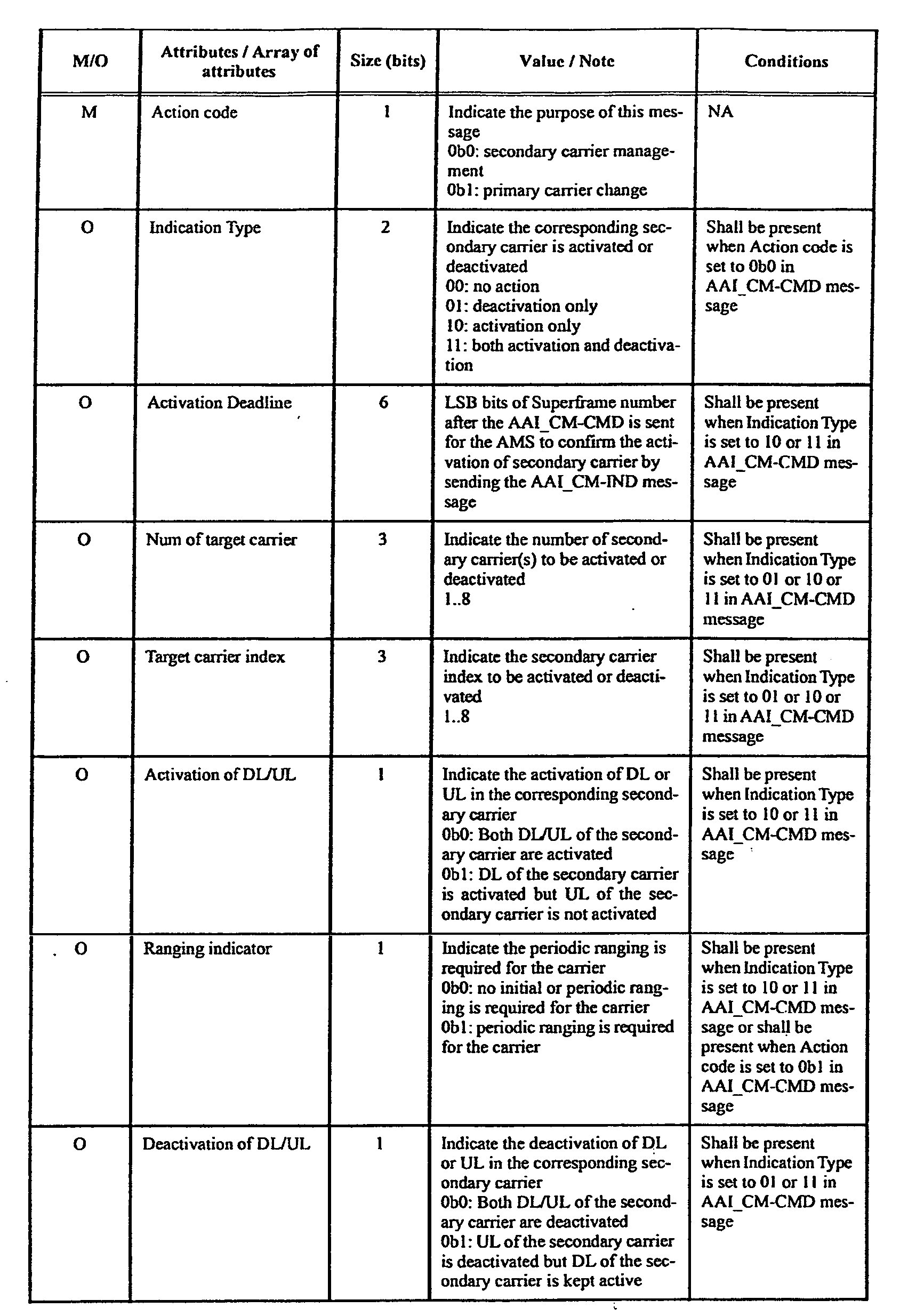
- the base station may instruct the terminal to activate / deactivate the allocated carriers allocated to the terminal according to the determination based on the QoS request, through the carrier management command (AAI_CM-CMD) message.
- the format of the carrier management command message may be as shown in Table 1 below.
- an AAI_CM-CMD message may include an action code, an indication type, an activation limit, a number of target carriers, a target carrier index, a ranging indicator, an uplink indicator field, .
- Table 1 illustrates the parameters related to the activation / deactivation of the secondary carrier. If the message is used for primary carrier change, the other parameters (for example, the physical index of the primary carrier to be changed, An operation time indicating on a super frame basis, and a field indicating the next state of the previous primary carrier, etc.).
- FIG. 4 shows an example of a secondary carrier activation procedure according to an embodiment of the present invention.
- the base station uses three carriers C_0 to C_2 as available carriers, of which the C_0 carrier is set as the primary carrier of the terminal and the remaining carriers are set as the allocated secondary carriers (i.e., AAI_MC-REQ / RSP Message exchange has been completed).
- the mobile station can exchange data with the base station via the primary carrier C_0 (S401).
- the base station may transmit a scan response (AAI_SCN-RSP) message as needed to instruct the terminal to scan the allocated secondary carriers (S402).
- AI_SCN-RSP scan response
- the MS scans for C_1 and C_2 carriers (S403 and S404), and reports the result to the BS (S405).
- the base station and the UE may exchange AAI CMM-CMD messages to instruct the UE to activate the C_1 carrier in order to satisfy QoS or for other reasons while exchanging traffic (S406).
- the UE can perform the superframe header update (S408) or the periodic ranging (S409) of the target carrier (C_1) according to the parameter setting value of the AAI_CM-CMD message or as needed.
- the mobile station transmits an AAI_CM-IND message to the base station to notify the base station thereof (S410).
- the BS allocates the CQICH to the MS (S411), and the MS can report the CQI to the BS (S412).
- the terminal and the base station can exchange data through the primary carrier C_0 and the newly activated secondary carrier C_1, respectively (S413 and S414).
- the activation / deactivation of the secondary carrier is defined to be triggered according to the base station's judgment. That is, other allocated secondary carriers other than the primary carrier of the UE may be activated / deactivated only by the AAI_CM-CMD message determined by the base station.
- a terminal supporting a multicarrier can directly request a base station to activate a carrier.
- a terminal supporting a multicarrier can notify the base station through a predetermined medium access control message of the number of secondary carriers that can be supported when considering its battery mode (power mode) or power mode .
- the battery mode of the terminal according to the present embodiment is divided into three modes: 1) always on mode, 2) power saving mode, and 3) maximum power saving mode. It is also assumed that the terminal monitors the control channels of all activated carriers.
- FIG. 5 shows an example of a procedure in which a mobile terminal requests a base station to activate a carrier according to an embodiment of the present invention.
- step S307 of FIG. 3 it is assumed that the process after step S307 of FIG. 3 has been performed after the UE acquires the allocated carrier information from the base station.
- a terminal requests a base station to activate an allocated secondary carrier of an appropriate number (all or some of the allocated carriers) in consideration of its power mode (hereinafter referred to as a “carrier management request (AAI_CM-REQ)" message for convenience) (S501).
- the mobile station may send a message requesting the base station to activate the requested number of allocated carriers.
- the UE can request the base station through the same request message to activate only the number of carriers suitable for its power mode.
- the BS may transmit an AAI_CM-CMD message to the UE to activate the number of carriers requested by the UE among the allocated carriers of the UE (S502).
- the mobile station can activate the secondary carrier indicated by the AAI_CM-CMD message and transmit the AAI_CM-IND message to report the carrier activation state to the base station at a point indicated by the activation limit field in the AAI_CM-CMD message (S503) .
- the parameters of the carrier management request message transmitted from the UE to the BS in step S501 may include the following values.
- Type or Action code It is a field indicating the type of the requested carrier management procedure and is preferably set to a value indicating the activation of the secondary carrier.
- This parameter means the minimum value of the secondary carrier (that is, the carrier to be activated) from which the base station can indicate activation among the allocated carriers of the terminal . In other words, it means that the terminal requests the base station to always activate the secondary carrier by the value Nmin of this parameter.
- the UE may change the value of this parameter by retransmitting the AAI_CM-REQ message.
- This parameter specifies the number of the secondary carrier (that is, the carrier to be activated) that the base station can instruct activation according to the power mode status of the allocated carriers of the terminal, .
- the secondary carrier exceeding the value (Nmax) of this parameter is not supported.
- the UE may change the value of this parameter by retransmitting the AAI_CM-REQ message.
- Table 2 shows an example of a form in which the minimum number of active carriers field is included in the AAI_CM-REQ message according to an embodiment of the present invention.
- the Minimum Number of Carriers (Nmin) field may have a value between 1 and the number of allocated carriers (M) of the UE. If the corresponding field is set to 1, it indicates that the terminal requests the base station to always activate only the primary carrier. If the corresponding field is set to M, it indicates that the terminal requests the base station to always activate all allocated carriers.
- the number of carriers of the value Nmin of the least active carrier field is always activated. If necessary, the number of (Nmin + 1) (M) can instruct the terminal whether to activate the AAI_CM-CMD message according to its own decision.
- Table 3 shows an example of a mode in which the maximum number of active carriers field is included in the AAI_CM-REQ message according to an embodiment of the present invention.
- the Maximum Number of Carriers (Nmax) field may have a value between 1 and the number of allocated carriers (M) of the UE.
- M the number of allocated carriers
- the base station that has received the AAI_CM-REQ message having the configuration as shown in Table 3 can allocate only the number of carriers equal to the value (Nmax) of the maximum number of active carriers field to the active carrier of the UE. That is, the base station can indicate to the terminal whether to activate / deactivate the terminal for carriers ranging from one to the number of allocated carriers (M) through the AAI_CM-CMD message.
- Table 4 shows an example of a form in which the maximum number of active carriers field and the minimum number of active carriers field are included in the AAI_CM-REQ message according to an embodiment of the present invention.
- the AAI_CM-REQ message together with the minimum number of active carriers field described above with reference to Table 2 and the maximum number of active carriers field described above with reference to Table 3 can be included.
- the description of each field is similar to that described in Table 2 and Table 3, so that redundant description will be omitted for simplicity of description.
- the base station When the base station receives the AAI_CM-REQ message having the configuration as shown in Table 4, the BS always activates the allocated carriers corresponding to the minimum number of active carriers field value, but does not exceed the maximum number of active carriers field, It is possible to determine whether or not to activate the remaining secondary carriers.
- a method for requesting activation of a carrier from a base station in such a manner that the terminal informs the base station of its power mode or the battery level itself.
- a terminal supporting a multicarrier can report its power mode to the base station periodically or whenever a mode is changed.
- the base station may determine whether to activate the allocated carrier according to the power mode of the reported terminal. This may be used in conjunction with a message or an extension header (EH) to report a general battery level to the base station.
- EH extension header
- the battery mode of the terminal according to the present embodiment is divided into three modes: 1) always on mode, 2) power saving mode, and 3) maximum power saving mode. It is also assumed that the terminal monitors the control channels of all activated carriers.
- FIG. 6 shows an example of a procedure for a mobile station to request a base station to activate a carrier according to an embodiment of the present invention.
- step S307 in FIG. 3 it is assumed that the process after step S307 in FIG. 3 is completed after the UE acquires the allocated carrier information from the BS.
- the terminal transmits information on its power mode to the base station (S601).
- the power mode information may include various types of information such as an extended header (EH), a signaling header, a MAC management message or a feedback channel Lt; / RTI > to the base station.
- EH extended header
- Lt MAC management message
- Lt feedback channel
- RTI > feedback channel
- the BS receiving the power mode information of the MS may indicate the carrier information to be activated to the MS in consideration of the power mode through the AAI_CM-CMD message in step S602.
- the base station may not be able to activate all the allocated carriers that the terminal can support, To further reduce the signaling overhead that may occur. That is, the base station can indicate through the AAI_CM-CMD message that all or some of the allocated carriers that can be supported by the corresponding terminal can be activated for the terminal reporting that the power mode is "always on mode". In addition, the base station may reallocate the feedback channel so that the terminal may perform feedback (e.g., CQI) reporting more frequently. In addition, the base station may indicate via the AAI_CM-CMD message that the terminal no longer needs to report the battery level or power mode, or may no longer expect battery level reporting from the terminal.
- the base station may indicate via the AAI_CM-CMD message that the terminal no longer needs to report the battery level or power mode, or may no longer expect battery level reporting from the terminal.
- the active carrier of the terminal can be determined considering the power mode in order to more efficiently support the power saving of the terminal.
- the UE can transmit the AAI_CM-IND message to activate the secondary carrier indicated by the AAI_CM-CMD message and report the carrier activation state to the base station at the time point indicated by the activation limit field in the AAI_CM-CMD message (S603) .
- a signaling header for reporting a battery level of the terminal to a base station is a value indicating a signaling header for battery level reporting, a flow identifier field set to a value indicating a signaling header (i.e., 0001) Set type field.
- a length field indicating the length of the signaling header a battery status (AMS battery status) field indicating whether the power cord is connected, a battery level indication field indicating whether detailed information on the battery level is included, and the like . If the battery level indication field is set to 1, the AMS Battery Level field indicating the battery level of the terminal in units of a predetermined percentage may be further included in the present signaling header.
- a method for requesting activation of a carrier from a base station by a method for a terminal to inform its base station of its preferred carrier management mode.
- a terminal supporting a multicarrier can report its preferred carrier management mode among the predetermined one or more carrier management modes periodically or whenever the mode is changed. This is typically used with a report message or signaling header informing the base station of the battery level, or may be reported to the base station via the AAI_CM-REQ message described above.
- At least some of the allocated carriers can be activated / deactivated depending on the load status of the service or base station.
- the terminal can request the base station the number of preferred maximum / minimum active carriers.
- the above-described classification of the carrier management mode is exemplary, and the carrier management mode may be configured with fewer modes or more.
- Table 6 shows an example of a form of a carrier management request message for the UE to inform the base station of the carrier management mode according to another embodiment of the present invention.
- a carrier management mode (Carrier management mode) field is additionally included in the Carrier Management Request (AAI_CM-REQ) message according to the present embodiment to indicate a carrier management mode requested by the terminal to the base station. If the corresponding field is set to 0b10, the maximum number of active carriers field and the minimum number of active carriers field may be further included in the present message.
- Table 7 shows an example of a carrier management mode report message for informing the base station of the carrier management mode according to another embodiment of the present invention.
- the carrier management mode report message includes a carrier management mode field as a message newly defined in the present invention to report only the carrier management mode, And can indicate the carrier management mode. If the corresponding field is set to 0b10, the maximum number of active carriers field and the minimum number of active carriers field may be further included in the present message.
- FBS terminal and a base station
- MBS base station
- the terminal may operate as a transmitter in an uplink and as a receiver in a downlink.
- the base station can operate as a receiver in an uplink and operate as a transmitter in a downlink. That is, the terminal and the base station may include a transmitter and a receiver for transmission of information or data.
- the transmitter and receiver may comprise a processor, module, part and / or means, etc., for performing embodiments of the present invention.
- the transmitter and receiver may include a module (means) for encrypting the message, a module for interpreting the encrypted message, an antenna for transmitting and receiving the message, and the like. An example of such a transmitting end and a receiving end will be described with reference to FIG.
- FIG. 7 is a block diagram showing an example of a structure of a transmitting end and a receiving end, according to another embodiment of the present invention.
- each of the transmitting end and the receiving end includes antennas 5 and 10, processors 20 and 30, transmission modules (Tx modules 40 and 50), reception modules (Rx modules 60 and 70), and memories 80 and 90 .
- Each component can perform a function corresponding to each other. Each component will be described in more detail below.
- the antennas 5 and 10 transmit the signals generated by the transmission modules 40 and 50 to the outside or receive radio signals from the outside and transmit the signals to the reception modules 60 and 70. If a multi-antenna (MIMO) function is supported, more than two may be provided.
- MIMO multi-antenna
- the antenna, the transmitting module and the receiving module can together form a wireless communication (RF) module.
- RF wireless communication
- the processors 20 and 30 typically control the overall operation of the mobile terminal as a whole. For example, a controller function, a service characteristic, and a MAC (Medium Access Control) frame variable control function, a handover function, an authentication and encryption function, and the like for performing the above- . More specifically, the processors 20 and 30 may perform overall control for performing the handover procedure shown in FIGS.
- a controller function For example, a controller function, a service characteristic, and a MAC (Medium Access Control) frame variable control function, a handover function, an authentication and encryption function, and the like for performing the above- . More specifically, the processors 20 and 30 may perform overall control for performing the handover procedure shown in FIGS.
- MAC Medium Access Control
- the processor of the mobile terminal can acquire information on the available carriers of the base station through a multicarrier-related message (for example, AAI_MC-ADV, AAI_Global-config) and transmits an AAI_MC-REQ / RSP message exchanged with the base station To obtain allocated carrier information.
- the processor of the mobile terminal can determine an instruction regarding the carrier management through the AAI_CM-CMD message and notify the base station of the fulfillment of the corresponding instruction through the AAI_CM-IND message.
- the transmission of the AAI_CM-IND message is preferably performed before or at the time indicated by the Activation Deadline field included in the AAI_CM-CMD message.
- the processor of the UE can control the base station to request the base station to activate its allocated carrier by notifying the base station of its state (e.g., power level) through various methods.
- the processor of the terminal may perform an overall control operation of the operation procedure described in the above embodiments.
- the transmission modules 40 and 50 may perform predetermined coding and modulation on the data to be transmitted to the outside and transmit the data to the antenna 10 after being scheduled from the processors 20 and 30.
- the receiving modules 60 and 70 decode and demodulate the radio signals received from the outside through the antennas 5 and 10 to restore them in the form of original data and transmit them to the processors 20 and 30 .
- the memories 80 and 90 may store programs for processing and controlling the processors 20 and 30, and may perform functions for temporary storage of input / output data.
- the memories 80 and 90 may be a flash memory type, a hard disk type, a multimedia card micro type, a card type memory (for example, SD or XD memory A static random access memory (SRAM), a read-only memory (ROM), an electrically erasable programmable read-only memory (EEPROM), a programmable read-only memory (PROM) Magnetic disk, magnetic disk, magnetic disk, or optical disk.
- SRAM static random access memory
- ROM read-only memory
- EEPROM electrically erasable programmable read-only memory
- PROM programmable read-only memory
- the base station includes a controller function for performing the above-described embodiments of the present invention, orthogonal frequency division multiple access (OFDMA) packet scheduling, time division duplex (TDD) packet scheduling and channel multiplexing , MAC frame variable control function according to service characteristics and propagation environment, high speed traffic real time control function, handover function, authentication and encryption function, packet modulation / demodulation function for data transmission, high speed packet channel coding function and real time modem control function Etc. may be performed through at least one of the modules described above, or may include additional means, modules, or portions for performing such functions.
- OFDMA orthogonal frequency division multiple access
- TDD time division duplex
- Etc real time modem control function
Landscapes
- Engineering & Computer Science (AREA)
- Signal Processing (AREA)
- Computer Networks & Wireless Communication (AREA)
- Mobile Radio Communication Systems (AREA)
Abstract
Description
표 1
| Syntax | Size (bit) | Notes |
| Carrier Management Request message { | ||
| Management Message type = xxx | 8 | Carrier Management Request Message |
| Carrier Management Request type | 2 | 0b00: secondary carrier management |
| 0b01: primary carrier change | ||
| 0b10: carrier switching | ||
| 0b11: reserved | ||
| If (message type == 00){ | ||
| Minimum Number of carriers | TBD | 단말이 제어채널을 모니터링 할 수 있는 최소 캐리어의 수를 나타낸다. |
| } | ||
| If (message type == 01){ | ||
| … | TBD | 프라이머리 캐리어 변경이 단말에 의해 트리거(요청)되는 경우 필요한 파라미터가 정의될 수 있음 |
| } | ||
| If (message type == 10){ | ||
| … | TBD | 캐리어 스위칭이 단말에 의해 트리거(요청)되는 경우 필요한 파라미터가 정의될 수 있음 |
| } | ||
| } |
| Syntax | Size (bit) | Notes |
| Carrier Management Request message { | ||
| Management Message type = xxx | 8 | Carrier Management Request Message |
| Carrier Management Request type | 2 | 0b00: secondary carrier management |
| 0b01: primary carrier change | ||
| 0b10: carrier switching | ||
| 0b11: reserved | ||
| If (message type == 00){ | ||
| Maximum Number of carriers | TBD | 단말이 제어채널을 모니터링 할 수 있는 최대 캐리어의 수를 나타낸다. |
| } | ||
| If (message type == 01){ | ||
| … | TBD | 프라이머리 캐리어 변경이 단말에 의해 트리거(요청)되는 경우 필요한 파라미터가 정의될 수 있음 |
| } | ||
| If (message type == 10){ | ||
| … | TBD | 캐리어 스위칭이 단말에 의해 트리거(요청)되는 경우 필요한 파라미터가 정의될 수 있음 |
| } | ||
| } |
| Syntax | Size (bit) | Notes |
| Carrier Management Request message { | ||
| Management Message type = xxx | 8 | Carrier Management Request Message |
| Carrier Management Request type | 2 | 0b00: secondary carrier management |
| 0b01: primary carrier change | ||
| 0b10: carrier switching | ||
| 0b11: reserved | ||
| If (message type == 00){ | ||
| Maximum Number of carriers | TBD | 단말이 제어채널을 모니터링 할 수 있는 최대 캐리어의 수를 나타낸다. |
| Minimum Number of carriers | TBD | 단말이 제어채널을 모니터링 할 수 있는 최소 캐리어의 수를 나타낸다. |
| } | ||
| If (message type == 01){ | ||
| … | TBD | 프라이머리 캐리어 변경이 단말에 의해 트리거(요청)되는 경우 필요한 파라미터가 정의될 수 있음 |
| } | ||
| If (message type == 10){ | ||
| … | TBD | 캐리어 스위칭이 단말에 의해 트리거(요청)되는 경우 필요한 파라미터가 정의될 수 있음 |
| } | ||
| } |
표 5

| Syntax | Size (bit) | Notes |
| Carrier Management Request message { | ||
| Management Message type = xxx | 8 | Carrier Management Request Message |
| Carrier Management Request type | 2 | 0b00: secondary carrier management |
| 0b01: primary carrier change | ||
| 0b10: carrier switching | ||
| 0b11: reserved | ||
| If (message type == 00){ | Secondary carrier management | |
| Carrier management mode | 2 | 0b00: Static Mode |
| 0b01: Dynamic Mode | ||
| 0b10: Interactive Mode | ||
| 0b11: reserved | ||
| If (Carrier management mode == 10){ | Interactive Mode 인 경우 | |
| Maximum Number of carriers | TBD | 단말이 제어채널을 모니터링 할 수 있는 최대 캐리어의 수를 나타낸다. |
| Minimum Number of carriers | TBD | 단말이 제어채널을 모니터링 할 수 있는 최소 캐리어의 수를 나타낸다. |
| } | ||
| } | ||
| If (message type == 01){ | ||
| … | TBD | 프라이머리 캐리어 변경이 단말에 의해 트리거(요청)되는 경우 필요한 파라미터가 정의될 수 있음 |
| } | ||
| If (message type == 10){ | ||
| … | TBD | 캐리어 스위칭이 단말에 의해 트리거(요청)되는 경우 필요한 파라미터가 정의될 수 있음 |
| } | ||
| } |
| Syntax | Size (bit) | Notes |
| Carrier Management Mode Report { | ||
| Carrier management mode | 2 | 0b00: Static Mode |
| 0b01: Dynamic Mode | ||
| 0b10: Interactive Mode | ||
| 0b11: reserved | ||
| If (Carrier management mode == 10){ | Interactive Mode인 경우 | |
| Maximum Number of carriers | TBD | 단말이 제어채널을 모니터링 할 수 있는 최대 캐리어의 수를 나타낸다. |
| Minimum Number of carriers | TBD | 단말이 제어채널을 모니터링 할 수 있는 최소 캐리어의 수를 나타낸다. |
| } | ||
| } |
Claims (18)
- 멀티 캐리어를 지원하는 광대역 무선 접속 시스템에서 단말이 캐리어 관리를 수행하는 방법에 있어서,기지국으로부터 제 1 캐리어를 통하여 할당된 적어도 하나의 제 2 캐리어에 대한 활성화를 요청하는 활성화 요청 정보를 상기 기지국으로 전송하는 단계;상기 적어도 하나의 제 2 캐리어 중 적어도 하나의 대상 캐리어에 대한 활성화를 지시하는 활성화 지시 정보를 포함하는 제 1 메시지를 상기 기지국으로부터 수신하는 단계; 및상기 활성화에 따른 상기 적어도 하나의 대상 캐리어의 준비 여부를 상기 기지국에 알리기 위한 제 2 메시지를 상기 기지국으로 전송하는 단계를 포함하되,상기 활성화 요청 정보는 상기 단말의 전력상태에 따라 결정되는 것을 특징으로 하는 캐리어 관리 방법.
- 제 1항에 있어서,상기 활성화 요청 정보는,상기 적어도 하나의 제 2 캐리어 중 상기 단말이 활성화를 요청하는 최대 개수 및 최소 개수 중 적어도 하나를 포함하는, 캐리어 관리 방법.
- 제 1항에 있어서,상기 단말은 상기 전력상태에 따라 복수의 서로 다른 전력 모드 중 어느 하나로 동작하고,상기 활성화 요청 정보는,상기 전력 모드의 종류를 지시하는 것을 특징으로 하는 캐리어 관리 방법.
- 제 1항에 있어서,상기 활성화 요청 정보는,상기 단말의 전원 연결 여부 및 배터리 레벨 정보 중 적어도 하나를 포함하는, 캐리어 관리 방법.
- 제 1항에 있어서,상기 활성화 요청 정보는,소정의 매체접속제어 관리(MAC management) 메시지, 확장 헤더 또는 시그널링 헤더 중 어느 하나를 통하여 상기 기지국으로 전송되며,상기 제 1 메시지는 캐리어 관리 명령(AAI_CM-CMD) 메시지이고,상기 제 2 메시지는 캐리어 관리 지시(AAI_CM-IND) 메시지이며,상기 제 2 캐리어는 멀티 캐리어 응답(AAI_MC-RSP) 메시지를 통해 상기 단말에 할당되는 것을 특징으로 하는 캐리어 관리 방법.
- 제 1항에 있어서,상기 제 1 캐리어는 프라이머리 캐리어(primary carrier)이고,상기 제 2 캐리어는 상기 기지국으로부터 상기 단말에 할당된 세컨더리 캐리어(assigned secondary carrier)인 것을 특징으로 하는 캐리어 관리 방법.
- 멀티 캐리어를 지원하는 광대역 무선 접속 시스템에서 기지국이 단말의 캐리어를 관리하는 방법에 있어서,제 1 캐리어를 통하여 단말에 할당한 적어도 하나의 제 2 캐리어에 대한 활성화를 요청하는 활성화 요청 정보를 상기 단말로부터 수신하는 단계;상기 활성화 요청 정보를 이용하여 상기 적어도 하나의 제 2 캐리어 중 활성화될 적어도 하나의 대상 캐리어를 결정하는 단계; 및상기 적어도 하나의 대상 캐리어에 대한 활성화를 지시하는 활성화 지시 정보를 포함하는 제 1 메시지를 단말로 전송하는 단계를 포함하되,상기 활성화 요청 정보는 상기 단말의 전력상태에 따라 결정되는 것을 특징으로 하는 캐리어 관리 방법.
- 제 7항에 있어서,상기 활성화 요청 정보는,상기 적어도 하나의 제 2 캐리어 중 상기 단말이 활성화를 요청하는 최대 개수 및 최소 개수 중 적어도 하나를 포함하는, 캐리어 관리 방법.
- 제 7항에 있어서,상기 단말은 상기 전력상태에 따라 복수의 서로 다른 전력 모드 중 어느 하나로 동작하고,상기 활성화 요청 정보는,상기 전력 모드의 종류를 지시하는 것을 특징으로 하는 캐리어 관리 방법.
- 제 7항에 있어서,상기 활성화 요청 정보는,상기 단말의 전원 연결 여부 및 배터리 레벨 정보 중 적어도 하나를 포함하는, 캐리어 관리 방법.
- 제 7항에 있어서,상기 활성화 요청 정보는,소정의 매체접속제어 관리(MAC management) 메시지, 확장 헤더 또는 시그널링 헤더 중 어느 하나를 통하여 상기 기지국으로 전송되며,상기 제 1 메시지는 캐리어 관리 명령(AAI_CM-CMD) 메시지이고,상기 제 2 메시지는 캐리어 관리 지시(AAI_CM-IND) 메시지이며,상기 제 2 캐리어는 멀티 캐리어 응답(AAI_MC-RSP) 메시지를 통해 상기 단말에 할당되는 것을 특징으로 하는 캐리어 관리 방법.
- 제 7항에 있어서,상기 제 1 캐리어는 프라이머리 캐리어(primary carrier)이고,상기 제 2 캐리어는 상기 기지국으로부터 상기 단말에 할당된 세컨더리 캐리어(assigned secondary carrier)인 것을 특징으로 하는 캐리어 관리 방법.
- 광대역 무선 접속 시스템에서 멀티 캐리어 동작(multi-carrier operation)을 지원하는 이동 단말기에 있어서,프로세서; 및상기 프로세서의 제어에 따라 외부와 무선 신호를 송수신하기 위한 무선통신(RF) 모듈을 포함하되,상기 프로세서는,기지국으로부터 제 1 캐리어를 통하여 할당된 적어도 하나의 제 2 캐리어에 대한 활성화를 요청하는 활성화 요청 정보를 자신의 전력 상태에 따라 생성하여 상기 기지국으로 전송되도록 하고, 상기 적어도 하나의 제 2 캐리어 중 적어도 하나의 대상 캐리어에 대한 활성화를 지시하는 활성화 지시 정보를 상기 기지국으로부터 수신되는 제 1 메시지를 통하여 획득하도록 제어하는 것을 특징으로 하는 이동 단말기.
- 제 13항에 있어서,상기 프로세서는,상기 활성화에 따른 상기 적어도 하나의 대상 캐리어의 준비 여부를 상기 기지국에 알리기 위한 제 2 메시지가 상기 기지국으로 전송되도록 제어하는 것을 특징으로 하는 이동 단말기.
- 제 14항에 있어서,상기 활성화 요청 정보는,상기 적어도 하나의 제 2 캐리어 중 상기 단말이 활성화를 요청하는 최대/최소 개수, 상기 단말의 전원 연결 여부 및 배터리 레벨 정보 중 적어도 하나를 포함하는, 이동 단말기.
- 제 14항에 있어서,상기 프로세서는,상기 전력상태에 따라 복수의 서로 다른 전력 모드 중 어느 하나로 동작하도록 제어하고,상기 활성화 요청 정보는,상기 전력 모드의 종류를 지시하는 것을 특징으로 하는 이동 단말기.
- 제 14항에 있어서,상기 활성화 요청 정보는,소정의 매체접속제어 관리(MAC management) 메시지, 확장 헤더 또는 시그널링 헤더 중 어느 하나를 통하여 상기 기지국으로 전송되며,상기 제 1 메시지는 캐리어 관리 명령(AAI_CM-CMD) 메시지이고,상기 제 2 메시지는 캐리어 관리 지시(AAI_CM-IND) 메시지이며,상기 제 2 캐리어는 멀티 캐리어 응답(AAI_MC-RSP) 메시지를 통해 할당되는 것을 특징으로 하는 이동 단말기.
- 제 14항에 있어서,상기 제 1 캐리어는 프라이머리 캐리어(primary carrier)이고,상기 제 2 캐리어는 할당 세컨더리 캐리어(assigned secondary carrier)인 것을 특징으로 하는 이동 단말기.
Priority Applications (1)
| Application Number | Priority Date | Filing Date | Title |
|---|---|---|---|
| US13/377,813 US8917643B2 (en) | 2009-06-12 | 2010-06-14 | Method for efficiently managing carriers in broadband wireless access system |
Applications Claiming Priority (4)
| Application Number | Priority Date | Filing Date | Title |
|---|---|---|---|
| US18638409P | 2009-06-12 | 2009-06-12 | |
| US61/186,384 | 2009-06-12 | ||
| KR1020100055858A KR101706945B1 (ko) | 2009-06-12 | 2010-06-14 | 광대역 무선 접속시스템에서 효율적인 캐리어 관리 방법 |
| KR10-2010-0055858 | 2010-06-14 |
Publications (4)
| Publication Number | Publication Date |
|---|---|
| WO2010143925A2 WO2010143925A2 (ko) | 2010-12-16 |
| WO2010143925A3 WO2010143925A3 (ko) | 2011-03-03 |
| WO2010143925A9 WO2010143925A9 (ko) | 2011-04-21 |
| WO2010143925A4 true WO2010143925A4 (ko) | 2011-08-18 |
Family
ID=43309395
Family Applications (1)
| Application Number | Title | Priority Date | Filing Date |
|---|---|---|---|
| PCT/KR2010/003807 Ceased WO2010143925A2 (ko) | 2009-06-12 | 2010-06-14 | 광대역 무선 접속시스템에서 효율적인 캐리어 관리 방법 |
Country Status (2)
| Country | Link |
|---|---|
| US (1) | US8917643B2 (ko) |
| WO (1) | WO2010143925A2 (ko) |
Families Citing this family (15)
| Publication number | Priority date | Publication date | Assignee | Title |
|---|---|---|---|---|
| WO2006105010A1 (en) | 2005-03-25 | 2006-10-05 | Neocific, Inc. | Methods and apparatus for cellular broadcasting and communication system |
| CN101091390B (zh) | 2005-06-09 | 2011-01-12 | 桥扬科技有限公司 | 用于高功率效率的广播和通信系统的方法和设备 |
| CN102461238B (zh) * | 2009-06-19 | 2015-05-13 | 诺基亚公司 | 用于管理载波测量的方法和装置 |
| US8265625B2 (en) * | 2009-08-20 | 2012-09-11 | Acer Incorporated | Systems and methods for network entry management |
| WO2012050838A1 (en) | 2010-09-28 | 2012-04-19 | Neocific, Inc. | Methods and apparatus for flexible use of frequency bands |
| WO2012044227A1 (en) * | 2010-10-01 | 2012-04-05 | Telefonaktiebolaget L M Ericsson (Publ) | Methods providing aided signal synchronization and related network nodes and devices |
| WO2012079197A1 (en) * | 2010-12-16 | 2012-06-21 | Nokia Siemens Networks Oy | Common control deactivation in carrier aggregation |
| WO2012115414A2 (en) | 2011-02-21 | 2012-08-30 | Samsung Electronics Co., Ltd. | Method and apparatus for saving power of user equipment in wireless communication system |
| JP6125437B2 (ja) | 2011-02-21 | 2017-05-10 | サムスン エレクトロニクス カンパニー リミテッド | 端末送信電力量を效率的に報告する方法及び装置 |
| KR101995293B1 (ko) | 2011-02-21 | 2019-07-02 | 삼성전자 주식회사 | 반송파 집적 기술을 사용하는 시분할 무선통신시스템에서 부차반송파의 활성화 또는 비활성화 방법 및 장치 |
| KR20140024900A (ko) * | 2011-05-26 | 2014-03-03 | 엘지전자 주식회사 | 무선 통신 시스템에서 클라이언트 협력을 위한 후보 협력 장치 리스트의 유효성 확인 방법 및 장치 |
| US9369905B2 (en) * | 2012-05-18 | 2016-06-14 | Qualcomm Incorporated | Battery power reporting for UE relays |
| JP5950785B2 (ja) * | 2012-10-05 | 2016-07-13 | 株式会社Nttドコモ | 無線基地局及び移動局 |
| US9414384B2 (en) * | 2013-09-17 | 2016-08-09 | Telefonaktiebolaget Lm Ericsson (Publ) | State-driven secondary cell activation and deactivation |
| US9775154B2 (en) * | 2015-10-15 | 2017-09-26 | Alcatel-Lucent Usa Inc. | Dynamic selection of band combinations for carrier aggregation |
Family Cites Families (5)
| Publication number | Priority date | Publication date | Assignee | Title |
|---|---|---|---|---|
| US7957351B2 (en) | 2005-04-04 | 2011-06-07 | Qualcomm Incorporated | Method and apparatus for management of multi-carrier communications in a wireless communication system |
| CN100574178C (zh) * | 2005-07-04 | 2009-12-23 | 上海原动力通信科技有限公司 | 实现多载波高速下行分组接入业务的设备、系统及方法 |
| CN100407802C (zh) * | 2005-08-28 | 2008-07-30 | 华为技术有限公司 | 一种多载波ev-do的反向链路管理方法及接入终端 |
| US20090093255A1 (en) * | 2007-10-05 | 2009-04-09 | Qualcomm Incorporated | Adjusting multi-carrier allocation in wireless networks |
| US8711785B2 (en) * | 2008-03-25 | 2014-04-29 | Qualcomm Incorporated | Fast carrier allocation in multi-carrier systems |
-
2010
- 2010-06-14 US US13/377,813 patent/US8917643B2/en active Active
- 2010-06-14 WO PCT/KR2010/003807 patent/WO2010143925A2/ko not_active Ceased
Also Published As
| Publication number | Publication date |
|---|---|
| WO2010143925A9 (ko) | 2011-04-21 |
| WO2010143925A3 (ko) | 2011-03-03 |
| US8917643B2 (en) | 2014-12-23 |
| US20120230265A1 (en) | 2012-09-13 |
| WO2010143925A2 (ko) | 2010-12-16 |
Similar Documents
| Publication | Publication Date | Title |
|---|---|---|
| WO2010143925A4 (ko) | 광대역 무선 접속시스템에서 효율적인 캐리어 관리 방법 | |
| WO2010143924A2 (en) | Method of managing carriers in a broadband wireless access system | |
| WO2018128468A1 (en) | Method and apparatus for detecting signals of a downlink control channel in a wireless communication system | |
| WO2011102686A2 (en) | Method for managing carrier aggregation sets,and related devices | |
| WO2011129598A2 (ko) | 광대역 무선 접속 시스템에서 효율적인 세컨더리 캐리어 정보 갱신 방법 | |
| WO2017183926A1 (en) | Method for connecting to a base station with flexible bandwidth | |
| WO2010077116A2 (ko) | 광대역 지원을 위한 다중 캐리어 결합 상황에서의 효과적인 제어정보 전송 방법 | |
| WO2012108621A1 (ko) | 무선 접속 시스템에서 단말 간 협력적 통신을 수행하기 위한 방법 및 장치 | |
| WO2019147061A1 (ko) | 무선 통신 시스템에서 신호를 송수신하기 위한 방법 및 이를 위한 장치 | |
| WO2010047545A2 (ko) | 광대역 지원을 위한 다중 캐리어 결합 상황에서 효과적인 초기 접속 방식 | |
| WO2010117232A2 (ko) | 다중반송파 지원 광대역 무선 통신 시스템에서의 반송파 관리 절차 수행 방법 및 장치 | |
| WO2016163829A1 (ko) | 다수의 요소 반송파를 이용하는 무선 통신 시스템에서 서빙셀의 활성화/비활성화 지시 방법 및 장치 | |
| WO2019066438A1 (ko) | 무선 통신 시스템에서 부분적인 주파수 대역을 제어하는 방법 및 장치 | |
| WO2010101424A2 (ko) | 멀티캐리어 성능 협상방법 및 장치 | |
| WO2011004989A2 (ko) | 공유 무선 자원을 이용한 기지국의 상향링크 수신 방법 및 단말기의 상향링크 송신 방법 | |
| WO2021075669A1 (ko) | Nr v2x에서 사이드링크 그랜트를 기반으로 mac pdu를 전송하는 방법 및 장치 | |
| WO2022030991A1 (ko) | 무선 통신 시스템에서 무선 신호 송수신 방법 및 장치 | |
| WO2017204595A1 (ko) | Nr 시스템을 위한 제어 채널 및 데이터 채널 송수신 방법 및 장치 | |
| WO2016126027A1 (en) | Method for deactivating scells upon a tat expiry for pucch cell in a carrier aggregation system and a device therefor | |
| WO2011162572A2 (ko) | 다중 무선 접속 기술을 지원하는 무선 통신 시스템에서의 단말 간 협력 통신 | |
| WO2019117688A1 (ko) | 무선 통신 시스템에서 상향링크 제어 정보 전송 방법 및 상기 방법을 이용하는 장치 | |
| WO2016114581A1 (en) | Method for configuring an activated scell with pucch resource in a carrier aggregation system and a device therefor | |
| WO2012078000A2 (ko) | 무선통신 시스템에서 단말 및 기지국 간 접속 방법 및 그 장치 | |
| WO2018147568A1 (ko) | 무선 셀룰라 통신 시스템에서 랜덤 억세스를 수행하는 방법 및 장치 | |
| WO2011136618A2 (ko) | 멀티 캐리어 시스템에서 e-mbs 단말을 위한 페이징 방법 및 장치 |
Legal Events
| Date | Code | Title | Description |
|---|---|---|---|
| 121 | Ep: the epo has been informed by wipo that ep was designated in this application |
Ref document number: 10786408 Country of ref document: EP Kind code of ref document: A2 |
|
| NENP | Non-entry into the national phase in: |
Ref country code: DE |
|
| WWE | Wipo information: entry into national phase |
Ref document number: 65/KOLNP/2012 Country of ref document: IN |
|
| WWE | Wipo information: entry into national phase |
Ref document number: 13377813 Country of ref document: US |
|
| 122 | Ep: pct application non-entry in european phase |
Ref document number: 10786408 Country of ref document: EP Kind code of ref document: A2 |