WO2010146628A1 - Insertion light source - Google Patents
Insertion light source Download PDFInfo
- Publication number
- WO2010146628A1 WO2010146628A1 PCT/JP2009/002774 JP2009002774W WO2010146628A1 WO 2010146628 A1 WO2010146628 A1 WO 2010146628A1 JP 2009002774 W JP2009002774 W JP 2009002774W WO 2010146628 A1 WO2010146628 A1 WO 2010146628A1
- Authority
- WO
- WIPO (PCT)
- Prior art keywords
- light source
- magnet row
- insertion light
- magnet
- magnetic field
- Prior art date
- Legal status (The legal status is an assumption and is not a legal conclusion. Google has not performed a legal analysis and makes no representation as to the accuracy of the status listed.)
- Ceased
Links
Images







Classifications
-
- H—ELECTRICITY
- H05—ELECTRIC TECHNIQUES NOT OTHERWISE PROVIDED FOR
- H05H—PLASMA TECHNIQUE; PRODUCTION OF ACCELERATED ELECTRICALLY-CHARGED PARTICLES OR OF NEUTRONS; PRODUCTION OR ACCELERATION OF NEUTRAL MOLECULAR OR ATOMIC BEAMS
- H05H7/00—Details of devices of the types covered by groups H05H9/00, H05H11/00, H05H13/00
- H05H7/04—Magnet systems, e.g. undulators, wigglers; Energisation thereof
Definitions
- the present invention relates to an insertion light source that is inserted into a linear portion of an electron accelerator or an electron storage ring to generate high-luminance radiated light, and more particularly to an insertion light source that can be applied to an undulator and a free electron laser.
- An insertion light source composed of a permanent magnet or a permanent magnet and a magnetic material (iron or iron-cobalt alloy) is inserted in a form in which a vacuum chamber is sandwiched in a linear portion of an electron synchrotron accelerator, or in a form in which an electron trajectory is sandwiched in the chamber, It is useful as a device that generates radiated light stronger than the radiated light obtained from a conventional deflection magnet.
- FIG. 9 shows a conceptual diagram of the synchrotron accelerator and the insertion light source 31 introduced therein.
- the insertion light source 31 generates a sinusoidal periodic magnetic field in a vertical plane in the gap between the magnet rows.
- the insertion light source 31 that generates a periodic magnetic field is a hullback type (FIGS. 3A and 3B) composed of only the cuboid permanent magnet 22, a cuboid permanent magnet 22, and a cuboid magnetic material 26 of magnetic poles.
- a hybrid type Fig. 3C).
- Reference numeral 1 denotes an electron orbit. There are wiggler mode and undulator mode depending on the degree of meandering. Reference numeral 5 represents the amplitude of the electron orbit.
- the radiated light generated from each meander point is superimposed, and the luminance (photons / sec / mm 2 / mrad 2 /0.1% BW) is higher than that of the radiated light 35 from the deflection electromagnet 36 shown in FIG. Radiation light 10 to 1000 times larger can be obtained.
- reference numeral 30 indicates the emitted light from the insertion light source
- reference numeral 1-1 indicates the electron trajectory incident from the injector.
- Non-Patent Documents 1 to 3 Other characteristics of undulator mode synchrotron radiation include high directivity, quasi-monochromaticity that emits only basic energy (and its harmonics) due to interference effects, and high-coherence characteristics similar to lasers. Note that the insertion light source is disclosed in, for example, Non-Patent Documents 1 to 3.
- the basic energy of the light emitted from the insertion light source is expressed by the following formula using a practical unit.
- parameter K in the formula (1) is defined by the following formula.
- ⁇ 1 is the fundamental energy of the emitted radiation
- E is the kinetic energy of the charged particles passing through the insertion light source (equal to the electron storage energy of the synchrotron radiation synchrotron)
- ⁇ u is the period length of the magnetic field period
- B0 is the magnetic field intensity received by the electrons and is a function of the magnet array gap value (gap), and can be approximated by the following equation.
- D and C are constants that vary depending on the material and shape of the magnet, and x is a gap (gap value between magnet rows; unit mm).
- ⁇ Whether the insertion light source is in wiggler mode or undulator mode is classified according to the K value defined in equation (2).
- the gap is widened, the B0 and K values become smaller, the amplitude 5 of the electron orbit 1 becomes smaller, and the photon energy becomes smaller. If the gap is narrowed, the B0 and K values increase, the amplitude 5 of the electron orbit 1 increases, and the photon energy increases.
- the insertion light source loses the properties of undulator radiation such as high brightness and quasi-monochromaticity.
- K is sufficiently larger than 1
- the wiggler mode is set and the luminance decreases by about 1 to 3 digits, and the components on the higher photon energy side than the basic energy increase, and the thermal load on the optical system and the measurement system increases remarkably. This thermal load becomes a serious problem in a third generation light source with a small electron emittance, and sometimes destroys an optical system and a measurement system.
- Non-Patent Document 2 discloses a technique that uses two sets of upper and lower sets of four magnet rows instead of the upper and lower sets of two magnet rows of the normal undulator shown in FIGS. 3A to 3C. Thereby, horizontal and vertical magnetic field dispersion is generated, and the electron trajectory is vibrated in the horizontal and vertical directions, so that horizontal linearly polarized light, circular deflection, vertical linear deflection, and the like can be generated. At the same time, higher-order light emission on the optical axis is suppressed, and the thermal load on the optical system is reduced.
- Non-Patent Document 3 discloses a technique that uses a total of six magnet rows in three pairs, upper and lower. As a result, the electron trajectory, which is a simple horizontal sine wave vibration of a normal insertion light source, is changed to a complex electron trajectory having a vibration component in the vertical direction, and polarization control or thermal load reduction is possible.
- the K value that greatly affects the luminance, quasi-monochromaticity, and the like cannot be made constant. This is because in the prior art, the basic energy is swept by changing the K value, that is, changing the gap of the magnet array. However, if the interval between the magnets constituting the magnet array is simply increased in order to change the period length ⁇ u of the magnetic field period, the magnetic field distribution deviates greatly from the sine wave, so that it does not function as an insertion electrode.
- An object of the present invention is to provide an insertion light source capable of obtaining high-luminance, quasi-monochromatic undulator radiation even during energy sweeping.
- an insertion light source having a permanent magnet or a first magnet row and a second magnet row provided with a permanent magnet and a magnetic pole material
- the first magnet row and the first light source An insertion light source further comprising a mechanism for changing a magnetic field period length of the magnetic field formed by the two magnet arrays, wherein the basic energy of the emitted light is swept by changing the magnetic field period length.
- the insertion light source for generating radiated light by meandering an electron beam with a periodic magnetic field having a sine waveform further includes a magnetic field period length changing means for changing the period length of the magnetic field period while maintaining the periodic magnetic field of the sine wave.
- the insertion light source is characterized by this.
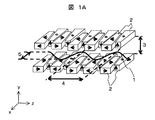
- FIG. 1A It is a perspective view which shows the example (The insertion light source comprised by a rectangular parallelepiped magnet, Fullblock Type) of the conventional insertion light source. It is a perspective view which shows the state which extended the magnet row
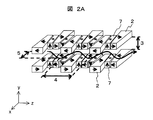
- FIG. 2B It is a schematic diagram (small magnetic field period) of the magnetic field period change in the insertion light source shown in FIG. 2B. It is a schematic diagram (large magnetic field period) of a magnetic field period change with the insertion light source shown to FIG. 2B. It is a schematic diagram (magnetic field period small) of the magnetic field period change in the other insertion light source (insertion light source consisting of an asymmetric trapezoidal column) according to the present embodiment. It is a schematic diagram (large magnetic field period) of the magnetic field period change with the other insertion light source (insertion light source which consists of an asymmetric trapezoid pillar) which concerns on a present Example. It is a schematic diagram for demonstrating the operation mechanism of the insertion light source which concerns on a present Example.
- This embodiment is characterized in that the radiant light energy that is normally swept by controlling the K value is characterized by sweeping the radiant light energy by changing the period length ( ⁇ u) of the magnetic field instead of fixing the K value. To do.
- the conventional undulators can be swept by changing the K value by manipulating the gap in both the basic and improved types.
- the insertion light source of the present embodiment realizes that energy can be swept while the K value is fixed by operating the gap and simultaneously changing the magnetic field period and the electron orbit period.
- the simplest mechanism for changing the magnetic field cycle is to open and close the distance between the normal cuboid magnet and the magnetic pole. However, if the distance between the magnets and the magnetic pole is increased too much, magnetic field leakage occurs and the magnetic field distribution becomes a sine wave. It seems that it is not the optimal method because it deviates greatly from.
- the inventor uses a magnet row / magnetic pole row in which trapezoidal or parallelogram-shaped magnets / magnetic pole materials are arranged instead of a normal rectangular parallelepiped, and changes the arrangement of magnets and magnetic poles in the magnet row / magnetic pole row.
- the insertion light source of the present embodiment by fixing the K value near 1, characteristics of undulator radiation such as high luminance and quasi-monochromaticity can be maintained in an ideal state even when the energy is swept.
- the quasi-monochromaticity since the quasi-monochromaticity is maintained, the heat load on the optical system / measurement system due to higher-order light does not increase significantly due to the energy sweep.
- FIG. 1A, 1B, 2A, and 2B show an example of an insertion light source according to the present embodiment.
- the arrow written in the magnet column indicates the magnetization direction.
- the x, y, and z axes are defined as shown in the lower left of FIGS. 1A and 1B, and this definition is used except for the plan view.
- FIG. 1A, FIG. 1B, FIG. 2A, and FIG. 2B only two magnetic field cycles are shown, but an actual insertion light source is configured with about 20 to 200 cycles.
- the magnet / magnetic pole material is a rectangular parallelepiped, and the magnetic field cycle cannot be changed.
- a magnetic pole array in which the trapezoidal column magnet 2 and the trapezoidal column magnetic pole material 6 are arranged as shown in FIGS. 1A and 1B, or the trapezoidal column magnet 2 and the parallelogram column as shown in FIGS. 2A and 2B.
- a magnetic pole array in which magnets 7 or parallelogram pole magnetic pole materials 8 are arranged is used. It is also possible to use a rhombus column in which the length of each side of the quadrilateral is equal.
- Both the trapezoidal column and the parallelogram column are arranged so that the trapezoidal surface or parallelogram surface thereof is parallel to the xz plane (electron trajectory surface), and the trapezoidal surface is an isosceles trapezoid for left and right objects.
- the dimensions of all trapezoidal column magnets are the same in the same insertion light source, and the dimensions of parallelogram column magnets and magnetic pole materials are also the same.
- the angle of the hypotenuse of the parallelogram is equal to the angle of the trapezoid hypotenuse of the trapezoidal column to the parallel knitting of the trapezoidal column. Arranged parallel to the hypotenuse.
- the trapezoidal columnar magnet has a trapezoidal surface that is not an isosceles trapezoid, and this mechanism can be realized by using a general trapezoid with a right-left ratio.
- a trapezoidal column magnetic field leakage when changing the period length can be reduced.
- the magnetic field around the magnet is highly symmetric, and when sweeping the energy of the radiated light, the deterioration of the sine waveform of the magnetic field period can be prevented or reduced. Therefore, an isosceles trapezoid trapezoidal column is suitable.
- the electron orbit period 4 ( ⁇ u) synchronized with the magnetic field period can be changed by shifting the arrangement of the array and the magnetic pole array in the x direction. At this time, if there is a gap between the magnet arrays (or between the magnet and the magnetic pole material), the magnetic field leaks and the magnetic field distribution deviates from the sine wave, so that the entire magnet array / magnetic pole array is expanded and contracted in the z direction.
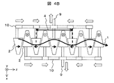
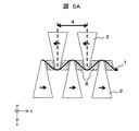
- FIG. 4A, 4B, FIG. 5A, and FIG. 5B conceptually show the lower magnet array arrangement and the electron trajectory of FIG. 1A and FIG. 2B, respectively, and the axis direction is shown in the lower left. .
- the magnet array and magnetic pole array move so that the electron trajectory is always in the center of the magnet array.
- the entire magnetic pole array is moved to simultaneously move the gap 3 in FIGS. 1A and 1B and FIGS. 2A and 2B.
- the K value that is regarded as important in this embodiment is a value that physically represents the relationship between the electron orbit period 4 and the electron orbit amplitude 5 in FIGS. 1A, 1B, 2A, and 2B. Keeping the K value constant near 1 means that the relationship between the electron orbit period 4 and the electron orbit amplitude 5 is ideally maintained for undulator radiation.
- the K value near 1 means a range of 0.9 to 1.1, and more preferably a range of 0.99 to 1.01.
- FIG. 4A The operation mechanism of the insertion light source composed of the trapezoidal column magnet of FIG. 1A will be described.
- two support rods (z-axis drive mechanism) 10 (or a plate-like shape) in which each trapezoidal column magnet 2 is alternately placed in parallel with the x-axis in a symmetrical position.
- the x-axis (x-direction) drive mechanism 9 is used to move the support bars (z-axis drive mechanism) 10 in the direction of reducing the distance between them, and to increase the support period (z-axis drive).
- the mechanism) 10 is moved in a direction that increases the distance between them.
- FIG. 4A is a schematic diagram when the magnetic field period 4 is small
- FIG. 4B is a schematic diagram when the magnetic field period 4 is large.
- the support rod 10 is fixed to a single rod or plate, and a mechanism (y-axis drive mechanism) 11 that moves the entire magnet array in the y-axis direction using this mechanism can be realized.
- FIG. 4A, 4B, and 7 illustrate the insertion light source including only the trapezoidal column magnet of FIG. 1A.
- the insertion light source including the trapezoidal column magnet 2 and the trapezoidal column magnetic pole material 6 as illustrated in FIG. Can be achieved.
- the parallelogram column pole material or the parallelogram column magnet is moved in the x direction.
- the drive mechanism of the trapezoidal column magnet 2 is the same as that shown in FIGS. 4A and 4B, and the drive of the parallelogram column is added independently from the drive mechanism of the trapezoidal column magnet from the top and bottom (y direction). A way to do this is considered.
- the electron orbit period 4 is limited to 2 to 4 times the long side of the trapezoidal column magnet 2. If the margin between magnets is not taken into consideration at this time, it is desirable that the ratio of the short side to the long side of the isosceles trapezoidal trapezoidal trapezoid is 1: 2 from the viewpoint of preventing magnetic field leakage. Actually, a margin of about several millimeters is made between the magnets, and the ratio of the long side to the single side changes accordingly.
- variable range of the orbital period becomes the widest after all in the trapezoidal column magnet having a ratio of the short side to the long side of 1: 2 and the trapezoidal short side.
- a parallelogram pillar magnet / magnetic pole material having parallel sides of the same length, it is variable between 2 to 4 times the short side.
- FIG. 8A and 8B show graphs as an example of the effects of the present embodiment.
- FIG. 8A shows the spectrum of the undulator, and compares the results of changing the energy from 10.1 keV to 5.1 keV.
- the K value is changed from 1 (10.1 keV) to 2 (5.1 keV) in order to change the energy.
- a rare earth sintered magnet for example, a samarium cobalt (SmCo) magnet or a neodymium (NdFeB) magnet is desirable. This is because these magnets have high magnetic properties and can secure the air gap magnetic field strength even if the cycle length is shortened, and a large number of cycle lengths can be obtained with a straight portion having a certain length. Moreover, even if the gap length is large, it is easy to ensure the magnetic field strength.
- SmCo samarium cobalt
- NdFeB neodymium
- the present embodiment by providing a mechanism for changing the period length of the magnetic field period, it is possible to provide an insertion light source capable of obtaining high-luminance, quasi-monochromatic undulator radiation even during energy sweeping. .
- the insertion light source which can reduce the magnetic field leakage at the time of changing period length can be provided by making the shape of the permanent magnet used for the magnet row
- the shape of the permanent magnet an isosceles trapezoid, the magnetic field around the magnet is symmetric, there is little disturbance of the magnetic field, and when sweeping the energy of the emitted light, the deterioration of the sine waveform of the magnetic field cycle is prevented or reduced. can do.
- an electron synchrotron accelerator suitable for diffraction, spectroscopy, and various structural analyzes can be provided.
- Electron orbit 1-1 ... Electron orbit from an injector, 2 ... Trapezoidal column magnet, 3 ... Gap value (gap), 4 ... Electron orbit period, 5 ... Electron orbit amplitude, 6 ... Trapezoidal column pole material, 7 ... Parallelogram-shaped column magnets, 8 ... Parallelogram-shaped column pole materials, 9 ... x-direction drive mechanism, 10 ... z-direction drive mechanism, 11 ... y-direction drive mechanism, 22 ... rectangular parallelepiped magnet, 26 ... rectangular parallelepiped pole material, 30 ... Insertion light source radiation, 31... Insertion light source, 35... Deflection magnet radiation, 36.
Landscapes
- Physics & Mathematics (AREA)
- Optics & Photonics (AREA)
- Engineering & Computer Science (AREA)
- Plasma & Fusion (AREA)
- Spectroscopy & Molecular Physics (AREA)
- Particle Accelerators (AREA)
Abstract
Description
本発明は、電子加速器や電子蓄積リングの直線部に挿入して輝度の高い放射光を発生する挿入光源、特にアンジュレータおよび自由電子レーザーに適用できる挿入光源に関するものである。 The present invention relates to an insertion light source that is inserted into a linear portion of an electron accelerator or an electron storage ring to generate high-luminance radiated light, and more particularly to an insertion light source that can be applied to an undulator and a free electron laser.
永久磁石または永久磁石と磁性材(鉄や鉄コバルト合金)で構成される挿入光源は、電子シンクロトロン加速器の直線部分に真空チャンバーを挟む形、またはチャンバー内に電子軌道を挟む形で挿入され、従来の偏向磁石から得られる放射光よりも強力な放射光を発生する装置として有用である。 An insertion light source composed of a permanent magnet or a permanent magnet and a magnetic material (iron or iron-cobalt alloy) is inserted in a form in which a vacuum chamber is sandwiched in a linear portion of an electron synchrotron accelerator, or in a form in which an electron trajectory is sandwiched in the chamber, It is useful as a device that generates radiated light stronger than the radiated light obtained from a conventional deflection magnet.
図9にシンクロトロン加速器とそこに導入された挿入光源31の概念図を示す。挿入光源31は、磁石列間の空隙中垂直面内にサイン波状の周期磁場を発生する。周期磁場を発生する挿入光源31は、図3A~図3Cに示すように、直方体永久磁石22のみで構成されるハルバック型(図3A、図3B)と直方体永久磁石22と磁極の直方体磁性材26とで構成されるハイブリッド型(図3C)がある。
FIG. 9 shows a conceptual diagram of the synchrotron accelerator and the
図3Aに示すように、電子が挿入光源中を走行するとき、周期磁場により磁場に垂直な水平面内でサイン波状周期運動を行い、各蛇行点から放射光を生じる。符号1は電子軌道を示す。蛇行の程度により、ウィグラーモードとアンジュレータモードがある。符号5は電子軌道の振幅を示す。
As shown in FIG. 3A, when electrons travel through the insertion light source, a periodic magnetic field causes a sine wave-like periodic motion in a horizontal plane perpendicular to the magnetic field, and radiated light is generated from each meander point.
ウィグラーモードでは各蛇行点から発生する放射光が重畳され、図9に示す偏向電磁石36からの放射光35より輝度(photons/sec/mm2/mrad2/0.1%B.W.)が10~1000倍大きな放射光が得られる。
In the wiggler mode, the radiated light generated from each meander point is superimposed, and the luminance (photons / sec / mm 2 / mrad 2 /0.1% BW) is higher than that of the
アンジュレータモードでは各蛇行運動から発生する放射光は干渉し、基本エネルギーとその高次光では、ウィグラーより更に輝度が10~1000倍程度大きな光が得られる。図9において、符号30は挿入光源からの放射光を、符号1-1は入射器から入射した電子軌道を示す。
In the undulator mode, the radiated light generated from each meandering motion interferes, and with the basic energy and its higher order light, light that is about 10 to 1000 times brighter than the wiggler is obtained. In FIG. 9,
その他アンジュレータモード放射光の特徴として、高い指向性、干渉効果により基本エネルギー(とその倍波)だけが放出される準単色性、高いコヒーレンス性というレーザーに準じた特性が挙げられる。なお、挿入光源に関しては、例えば非特許文献1~3に開示されている。
Other characteristics of undulator mode synchrotron radiation include high directivity, quasi-monochromaticity that emits only basic energy (and its harmonics) due to interference effects, and high-coherence characteristics similar to lasers. Note that the insertion light source is disclosed in, for example, Non-Patent
挿入光源からの放射光の基本エネルギーは実用単位を用いて、以下の式で表される。 The basic energy of the light emitted from the insertion light source is expressed by the following formula using a practical unit.

また、式(1)のパラメーターKは次の式で定義される。 Further, the parameter K in the formula (1) is defined by the following formula.

式(1)、式(2)で、ε1は放射される放射光の基本エネルギー、Eは挿入光源内を通過する荷電粒子の運動エネルギー(放射光シンクロトロン加速器の電子蓄積エネルギーに等しい)、λuは磁場周期の周期長、B0は電子が受ける磁場強度であり磁石列間隙値(ギャップ)の関数であるが、次のような式で近似可能である。 In equations (1) and (2), ε1 is the fundamental energy of the emitted radiation, E is the kinetic energy of the charged particles passing through the insertion light source (equal to the electron storage energy of the synchrotron radiation synchrotron), λu Is the period length of the magnetic field period, and B0 is the magnetic field intensity received by the electrons and is a function of the magnet array gap value (gap), and can be approximated by the following equation.

D、Cは定数で磁石の材質、形状によって変わり、xはギャップ(磁石列間間隙値;単位mm)である。 D and C are constants that vary depending on the material and shape of the magnet, and x is a gap (gap value between magnet rows; unit mm).
挿入光源がウィグラーモードかアンジュレータモードになるかは、式(2)で定義したK値で分類される。K=1前後かそれ以下の場合はアンジュレータになり、K>>1になるとウィグラーモードになる。アンジュレータ放射はK=1付近で輝度が最大になる。 ∙ Whether the insertion light source is in wiggler mode or undulator mode is classified according to the K value defined in equation (2). When K = 1 or less, the undulator is selected, and when K >> 1, the wiggler mode is set. The undulator radiation has a maximum brightness around K = 1.
準単色光のアンジュレータ放射ではエネルギーを掃引する場合は、通常式(1)のK値を掃引して基本エネルギーの掃引を行う。K値の操作は式(2)、式(3)から解るようにB0値の操作で行われるが、具体的には式(3)のxを変える、つまり図3A、図3Bに示した上下磁石列間の間隙値(ギャップ)3を操作して、ギャップに逆比例するB0の値を操作する。 In the case of quasi-monochromatic undulator radiation, when the energy is swept, the basic energy is swept by sweeping the K value of equation (1). The operation of the K value is performed by the operation of the B0 value as understood from the equations (2) and (3). Specifically, x in the equation (3) is changed, that is, the up and down shown in FIGS. 3A and 3B. The gap value (gap) 3 between the magnet arrays is manipulated to manipulate the value of B0 that is inversely proportional to the gap.
ギャップを広げればB0とK値は小さくなり、電子軌道1の振幅5は小さくなり光子エネルギーは小さくなる。ギャップを狭めればB0とK値は大きくなり、電子軌道1の振幅5は大きくなり光子エネルギーは大きくなる。
If the gap is widened, the B0 and K values become smaller, the
しかし、K値を1より大きくすると、挿入光源は高輝度、準単色性といったアンジュレータ放射光の性質を失う。Kが1より十分大きくなるとウィグラーモードになり輝度が1~3桁程落ちる他、基本エネルギーより高光子エネルギー側の成分が増え、光学系と計測系の熱負荷が著しく増す。この熱負荷は電子エミッタンスの小さい第3世代光源では深刻な問題になり、時に光学系・計測系を破壊する。 However, if the K value is larger than 1, the insertion light source loses the properties of undulator radiation such as high brightness and quasi-monochromaticity. When K is sufficiently larger than 1, the wiggler mode is set and the luminance decreases by about 1 to 3 digits, and the components on the higher photon energy side than the basic energy increase, and the thermal load on the optical system and the measurement system increases remarkably. This thermal load becomes a serious problem in a third generation light source with a small electron emittance, and sometimes destroys an optical system and a measurement system.
非特許文献2には、図3A~図3Cに示した通常のアンジュレータの上下一組2本の磁石列に代えて、上下2組計4本の磁石列を用いる技術が開示されている。これにより、水平と垂直の磁場分散を発生させ、電子軌道を水平と垂直方向に振動させることで水平の直線偏光、円偏向、垂直の直線偏向等を発生可能にする。同時に光軸上の高次光放射が抑制され光学系に対する熱負荷が軽減される。
Non-Patent
非特許文献3には、上下の3組、計6本の磁石列を用いる技術が開示されている。これにより、通常の挿入光源の単純な水平面内サイン波振動である電子軌道を、垂直方向にも振動成分を持つ複雑な電子軌道に変え、偏光制御、或いは熱負荷軽減が可能である。
Non-Patent
しかしながら、上記従来技術では、輝度や準単色性等に大きな影響を及ぼすK値を一定にすることができない。これは、上記従来技術では、基本エネルギーの掃引をK値の変化、すなわち磁石列のギャップの変更で行なっていたためである。しかしながら、磁場周期の周期長λuを変えるために、単純に磁石列を構成する各磁石の間隔を広げたのでは磁場分布がサイン波から大きく外れるため挿入電極として機能しなくなる。 However, in the above-described conventional technology, the K value that greatly affects the luminance, quasi-monochromaticity, and the like cannot be made constant. This is because in the prior art, the basic energy is swept by changing the K value, that is, changing the gap of the magnet array. However, if the interval between the magnets constituting the magnet array is simply increased in order to change the period length λu of the magnetic field period, the magnetic field distribution deviates greatly from the sine wave, so that it does not function as an insertion electrode.
本発明の目的は、エネルギー掃引の際にも高輝度、準単色性のアンジュレータ放射光を得ることが可能な挿入光源を提供することにある。 An object of the present invention is to provide an insertion light source capable of obtaining high-luminance, quasi-monochromatic undulator radiation even during energy sweeping.
上記目的を達成するための一形態として、永久磁石、或いは永久磁石と磁極材を備えた第1の磁石列と第2の磁石列とを有する挿入光源において、前記第1の磁石列と前記第2の磁石列により形成される磁場の磁場周期長を可変とする機構を更に有し、前記磁場周期長の変更により放射光の基本エネルギーの掃引が行われるものであることを特徴とする挿入光源とする。 As an embodiment for achieving the above object, in an insertion light source having a permanent magnet or a first magnet row and a second magnet row provided with a permanent magnet and a magnetic pole material, the first magnet row and the first light source An insertion light source further comprising a mechanism for changing a magnetic field period length of the magnetic field formed by the two magnet arrays, wherein the basic energy of the emitted light is swept by changing the magnetic field period length. And
また、サイン波形を有する周期磁場により電子線を蛇行させて放射光を発生させる挿入光源において、サイン波の周期磁場を保持しつつ、前記磁場周期の周期長を変える磁場周期長変更手段を更に有することを特徴とする挿入光源とする。 The insertion light source for generating radiated light by meandering an electron beam with a periodic magnetic field having a sine waveform further includes a magnetic field period length changing means for changing the period length of the magnetic field period while maintaining the periodic magnetic field of the sine wave. The insertion light source is characterized by this.
エネルギー掃引の際にも高輝度、準単色性のアンジュレータ放射光を得ることが可能な挿入光源を提供することができる。 It is possible to provide an insertion light source capable of obtaining high-luminance, quasi-monochromatic undulator radiation even during energy sweeping.
本実施の形態は、通常K値を制御して掃引する放射光エネルギーを、K値を固定としその代わりに磁場の周期長(λu)の変化で放射光エネルギーを掃引する事を最大の特徴とする。 This embodiment is characterized in that the radiant light energy that is normally swept by controlling the K value is characterized by sweeping the radiant light energy by changing the period length (λu) of the magnetic field instead of fixing the K value. To do.
上述のように、従来のアンジュレータは基本形も改良型もギャップを操作し、K値を変化させる事でエネルギー掃引を可能としている。これに対して本実施の形態の挿入光源はギャップを操作すると同時に磁場周期・電子軌道周期を変化させる事でK値は固定したままでエネルギー掃引を可能にする事を実現する。 As described above, the conventional undulators can be swept by changing the K value by manipulating the gap in both the basic and improved types. On the other hand, the insertion light source of the present embodiment realizes that energy can be swept while the K value is fixed by operating the gap and simultaneously changing the magnetic field period and the electron orbit period.
磁場周期の変更機構としては、最も単純には通常の直方体磁石・磁極間の距離の開閉が考えるが、磁石間・磁極間距離をあまり拡げると、磁場漏れが発生するとともに、磁場分布がサイン波から大きく外れるため最適方法とは思われない。 The simplest mechanism for changing the magnetic field cycle is to open and close the distance between the normal cuboid magnet and the magnetic pole. However, if the distance between the magnets and the magnetic pole is increased too much, magnetic field leakage occurs and the magnetic field distribution becomes a sine wave. It seems that it is not the optimal method because it deviates greatly from.
そこで発明者は、通常の直方体の代わりに台形柱若しくは平行四辺形柱の磁石・磁極材を並べた磁石列・磁極列を用い、磁石列・磁極列内で磁石と磁極の配置を変えることで、磁石間・磁極間の距離を一定に保ち、磁場漏れを防ぐとともにサイン波を維持しつつ磁場周期・電子軌道周期の変更を行うことを考案した。
エネルギー掃引時に、K値を1前後或いはそれ以外の値に固定するには、λuの変化の他にB0の操作も必要であり、その値は式(2)を変形した次の関係を満たすように変更する。
Therefore, the inventor uses a magnet row / magnetic pole row in which trapezoidal or parallelogram-shaped magnets / magnetic pole materials are arranged instead of a normal rectangular parallelepiped, and changes the arrangement of magnets and magnetic poles in the magnet row / magnetic pole row. We have devised to keep the distance between magnets and magnetic poles constant, to prevent magnetic field leakage and to change the magnetic field period and electron orbital period while maintaining the sine wave.
In order to fix the K value to around 1 or other values during the energy sweep, it is necessary to operate B0 in addition to the change in λu, and the value satisfies the following relationship obtained by modifying equation (2): Change to

本実施の形態の挿入光源では、K値を1付近に固定することにより、高輝度、準単色性といったアンジュレータ放射光の特徴がエネルギーを掃引しても理想的な状態に保たれる。また、準単色性が保たれるため、高次光による光学系・計測系に対する熱負荷も、エネルギー掃引によって著しく増える事はない。 In the insertion light source of the present embodiment, by fixing the K value near 1, characteristics of undulator radiation such as high luminance and quasi-monochromaticity can be maintained in an ideal state even when the energy is swept. In addition, since the quasi-monochromaticity is maintained, the heat load on the optical system / measurement system due to higher-order light does not increase significantly due to the energy sweep.
以下、実施例により説明する。 Hereinafter, description will be made by way of examples.
実施例を、図1A~図8を用いて説明する。図1A、図1B、図2A、図2Bに本実施例に係る挿入光源の一例を示す。これらの図および以下の図で、磁石柱内に書かれた矢印は磁化方向を示す。また、x、y、z軸を図1A、図1Bの左下に示したように定義し、平面図以外はこの定義を用いる。図1A、図1B、図2A、図2Bでは磁場周期が2周期分しか示されていないが、実際の挿入光源は20~200周期程度で構成される。図3A~図3Cに示した通常の挿入光源では磁石・磁極材は直方体であり、磁場周期を変更する事は出来ない。 Examples will be described with reference to FIGS. 1A to 8. FIG. 1A, 1B, 2A, and 2B show an example of an insertion light source according to the present embodiment. In these figures and the following figures, the arrow written in the magnet column indicates the magnetization direction. The x, y, and z axes are defined as shown in the lower left of FIGS. 1A and 1B, and this definition is used except for the plan view. In FIG. 1A, FIG. 1B, FIG. 2A, and FIG. 2B, only two magnetic field cycles are shown, but an actual insertion light source is configured with about 20 to 200 cycles. In the normal insertion light source shown in FIGS. 3A to 3C, the magnet / magnetic pole material is a rectangular parallelepiped, and the magnetic field cycle cannot be changed.
本実施例では、図1A、図1Bに示すように台形柱磁石2と台形柱磁極材6を並べた磁極列、または図2A、図2Bに示すように台形柱磁石2と、平行四辺形柱磁石7または平行四辺形柱磁極材8を並べた磁極列を用いる。四辺形の各辺の長さが等しい菱形柱を用いることもできる。永久磁石と磁極材とを組み合わせることにより、永久磁石の磁力劣化を低減することができる。
In this embodiment, a magnetic pole array in which the
台形柱も平行四辺形柱もその台形面または平行四辺形面をxz面(電子軌道面)と平行になるように配置され、台形面は左右対象の等脚台形になっている。図1A、図1B、図2A、図2Bに示したように、同一の挿入光源では全ての台形柱磁石の寸法は同じであり、平行四辺形柱磁石・磁極材の寸法も同じである。 Both the trapezoidal column and the parallelogram column are arranged so that the trapezoidal surface or parallelogram surface thereof is parallel to the xz plane (electron trajectory surface), and the trapezoidal surface is an isosceles trapezoid for left and right objects. As shown in FIG. 1A, FIG. 1B, FIG. 2A, and FIG. 2B, the dimensions of all trapezoidal column magnets are the same in the same insertion light source, and the dimensions of parallelogram column magnets and magnetic pole materials are also the same.
平行四辺形柱磁石・磁極材を用いる場合は、平行四辺形の斜辺の平行辺に対する角度は、台形柱の台形の斜辺の平行編に対する角度と等しく、平行四辺形柱はその斜辺を台形柱の斜辺と平行になるように配置される。 When a parallelogram magnet or magnetic pole material is used, the angle of the hypotenuse of the parallelogram is equal to the angle of the trapezoid hypotenuse of the trapezoidal column to the parallel knitting of the trapezoidal column. Arranged parallel to the hypotenuse.
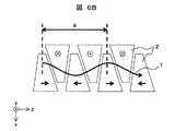
なお、図6A、図6Bに示すように、台形柱磁石の台形面は等脚台形でなく、一般の左右比対称の台形を用いてもこの機構は実現出来る。台形柱とすることにより、周期長を変える際の磁場漏洩を低減することができる。さらに、等脚台形を用いることにより、磁石周囲の磁場の対称性が高く、放射光のエネルギーを掃引する際、磁場周期のサイン波形の劣化を防止、或いは低減することができる。よって、等脚台形の台形柱が好適である。 Note that, as shown in FIGS. 6A and 6B, the trapezoidal columnar magnet has a trapezoidal surface that is not an isosceles trapezoid, and this mechanism can be realized by using a general trapezoid with a right-left ratio. By using a trapezoidal column, magnetic field leakage when changing the period length can be reduced. Furthermore, by using the isosceles trapezoid, the magnetic field around the magnet is highly symmetric, and when sweeping the energy of the radiated light, the deterioration of the sine waveform of the magnetic field period can be prevented or reduced. Therefore, an isosceles trapezoid trapezoidal column is suitable.
図4A、図4Bに示すように、台形の上底と下底とを交互に入れ替えた入れ子構造に配置された台形柱、或いは図5A、図5Bのような台形柱と平行四辺形柱の磁石列・磁極列配置をx方向にずらす事により、磁場周期に同期する電子軌道周期4(λu)の変更を可能にする。このとき、磁石列間(または磁石と磁極材間)に隙間が出来ると磁場が漏れ、磁場分布がサイン波から外れるため、磁石列・磁極列全体をz方向にも伸縮させる。 As shown in FIGS. 4A and 4B, trapezoidal columns arranged in a nested structure in which trapezoidal upper and lower bases are alternately replaced, or magnets of trapezoidal columns and parallelogram columns as in FIGS. 5A and 5B The electron orbit period 4 (λu) synchronized with the magnetic field period can be changed by shifting the arrangement of the array and the magnetic pole array in the x direction. At this time, if there is a gap between the magnet arrays (or between the magnet and the magnetic pole material), the magnetic field leaks and the magnetic field distribution deviates from the sine wave, so that the entire magnet array / magnetic pole array is expanded and contracted in the z direction.
図4A、図4Bと図5A、図5Bはそれぞれ図1Aと図2Bの、下側の磁石列配置と電子軌道を概念図的に示したものであり、左下に軸の方向が示されている。電子軌道は常に磁石列の中央に来るように磁石列・磁極列は動く。先に述べたように、K=1の関係を満たすためには、式(4)を満たすようにλuに同期してB0も変化する必要があり、通常のアンジュレータと同様y方向に磁石列・磁極列全体を動かして図1A、図1Bと図2A、図2Bのギャップ3も同時に動かす。
4A, 4B, FIG. 5A, and FIG. 5B conceptually show the lower magnet array arrangement and the electron trajectory of FIG. 1A and FIG. 2B, respectively, and the axis direction is shown in the lower left. . The magnet array and magnetic pole array move so that the electron trajectory is always in the center of the magnet array. As described above, in order to satisfy the relationship of K = 1, it is necessary to change B0 in synchronization with λu so as to satisfy the equation (4). The entire magnetic pole array is moved to simultaneously move the
本実施例で重要視しているK値は物理的には図1A、図1Bと図2A、図2Bの、電子軌道周期4と電子軌道振幅5の関係を表す値である。K値を1付近で一定に保つという事は電子軌道周期4と電子軌道振幅5の関係をアンジュレータ放射にとって理想的に保つことを意味する。なお、K値が1付近とは0.9~1.1の範囲をいい、より好ましくは0.99~1.01の範囲をいう。
The K value that is regarded as important in this embodiment is a value that physically represents the relationship between the
図1Aの台形柱の磁石からなる挿入光源について、動作機構を説明する。第一に図4Aに示したように各台形柱磁石2を互い違いにx軸に対して平行に対称位置に置かれた2本の支持棒(z軸駆動機構)10(または板状でもよい)に接続する。磁場周期4を小さくするにはx軸(x方向)駆動機構9を使って、支持棒(z軸駆動機構)10の互いの距離を縮める方向に動かし、大きくするには支持棒(z軸駆動機構)10の互いの距離を拡げる方向に動かす。
The operation mechanism of the insertion light source composed of the trapezoidal column magnet of FIG. 1A will be described. First, as shown in FIG. 4A, two support rods (z-axis drive mechanism) 10 (or a plate-like shape) in which each
この操作を単純に行うと、向かい合った台形柱磁石同士が干渉するので、x方向駆動に同期してz方向にも台形柱磁石2を動かす。このとき磁石列中心から離れた台形柱磁石2ほど大きく動かす必要があるが、支持棒(z軸駆動機構)10に釣り竿や指示棒等に用いられる伸縮機構を応用したものを用いる事で実現出来る。図4Aは磁場周期4が小さいとき、図4Bは磁場周期4が大きい時の模式図である。
If this operation is simply performed, the trapezoidal columnar magnets facing each other interfere with each other, so the trapezoidal
K=1を保つにはx、z方向に加え、y方向(ギャップ)も同期して動かす必要があるが、これは図7に示すように上述のx軸駆動機構9とz軸駆動機構(支持棒)10を一本の棒或いは板に固定し、この機構を用いて磁石列全体をy軸方向に動かす機構(y軸駆動機構)11で実現可能になる。
In order to keep K = 1, it is necessary to move the y direction (gap) in addition to the x and z directions in synchronism with each other, as shown in FIG. The
図4A、図4Bや図7では図1Aの台形柱磁石のみからなる挿入光源について例示したが、図1Bのような台形柱磁石2と台形柱磁極材6からなる挿入光源についても同じ機構で目的を達成出来る。
4A, 4B, and 7 illustrate the insertion light source including only the trapezoidal column magnet of FIG. 1A. However, the insertion light source including the
図5A、図5Bに示した台形柱磁石2と平行四辺形柱磁石7または平行四辺形柱磁極材8からなる挿入光源では平行四辺形柱磁極材または平行四辺形柱磁石についてはx方向に動かす必要はないが、z方向には動くような機構を付け加える必要がある。このときは、台形柱磁石2の駆動機構は図4A、図4Bと同様のものを用い、平行四辺形柱部の駆動は上下(y方向)から台形柱磁石の駆動機構とは独立して付加する方法が考えられる。
5A and 5B, in the insertion light source composed of the
図4A、図4Bから分かるように、台形柱磁石または台形柱磁極からなる挿入光源の場合、電子軌道周期4は台形柱磁石2の長辺の2倍から4倍に限られる。このとき、磁石同士のマージンを考えなければ、磁場漏れ防止の観点から台形柱切り口の等脚台形は短辺と長辺の比が1:2であることが望ましい。実際には磁石間に数mm程度のマージンを作るので、その分だけ長辺と単辺の比は変わってくる。
4A and 4B, in the case of an insertion light source composed of a trapezoidal column magnet or a trapezoidal column magnetic pole, the
台形柱磁石と平行四辺形柱磁石からなる挿入光源の場合も、結局最も軌道周期の可変範囲が広くなるのは短辺と長辺の比が1:2の台形柱磁石と台形の短辺と同じ長さの平行辺を持つ平行四辺形柱磁石・磁極材の場合で、短辺の2倍から4倍の間で可変になる。 Even in the case of an insertion light source composed of a trapezoidal column magnet and a parallelogram column magnet, the variable range of the orbital period becomes the widest after all in the trapezoidal column magnet having a ratio of the short side to the long side of 1: 2 and the trapezoidal short side. In the case of a parallelogram pillar magnet / magnetic pole material having parallel sides of the same length, it is variable between 2 to 4 times the short side.
式(1)で、例えばE=8の施設の場合、式(2)でK=1として計算すると、λu=2.6~5.2cmで16keV~7.8keVを、λu=5.2~10.4cmで7.8keV~3.9keVの基本エネルギーの発振が可能になる。これを実現するためには例えば、長辺と短辺の長さが1.6cmと4.2cmであるような台形柱磁石、同じく長辺と単辺の長さが4.2cmと9.4cmであるような台形柱磁石を左右にそれぞれ5mmのマージンをとって図1A、図1Bあるいは図6A、図6Bのように配置すればよい。また、例えば、E=3の施設の場合、λu=6~12cmが0.5~1.0keVに相当する。 For example, in the case of a facility with E = 8 in equation (1), if K = 1 is calculated in equation (2), 16 keV to 7.8 keV at λu = 2.6 to 5.2 cm, and λu = 5.2 to It is possible to oscillate a basic energy of 7.8 keV to 3.9 keV at 10.4 cm. In order to realize this, for example, a trapezoidal column magnet having long and short sides of 1.6 cm and 4.2 cm, and long and single sides of 4.2 cm and 9.4 cm are also used. Such trapezoidal columnar magnets may be arranged as shown in FIGS. 1A and 1B or FIGS. 6A and 6B with a margin of 5 mm on each side. For example, in the case of a facility with E = 3, λu = 6 to 12 cm corresponds to 0.5 to 1.0 keV.
図8A、図8Bに本実施例の効果の一例となるグラフを示す。図8Aはアンジュレータのスペクトルを計算したものであり、エネルギーを10.1keVから5.1keVに変化させた結果を比較している。この従来型アンジュレータではエネルギーを変化させるため、K値を1(10.1keV)から2(5.1keV)に変化させるが、K=1に比べK=2では多くの高次光成分が発生しているのが分かる。これら高次光成分はミラー分光器等の光学系に照射されると、多くの熱を発生し最悪の場合それらを破壊する。 8A and 8B show graphs as an example of the effects of the present embodiment. FIG. 8A shows the spectrum of the undulator, and compares the results of changing the energy from 10.1 keV to 5.1 keV. In this conventional undulator, the K value is changed from 1 (10.1 keV) to 2 (5.1 keV) in order to change the energy. However, many higher-order light components are generated at K = 2 compared to K = 1. I understand. When these higher-order light components are applied to an optical system such as a mirror spectroscope, they generate a lot of heat and destroy them in the worst case.
それに対し、図8Bの本実施例のアンジュレータの場合、エネルギーを16keVから7.8keVに変化させてもK=1の条件を維持出来るため、高次光の発生がどちらのエネルギーでも少ない事が分かる。以上よって、準単色性が保たれ、熱負荷を軽減出来る本実施例の効果が確認出来る。 On the other hand, in the case of the undulator of this embodiment shown in FIG. 8B, the condition of K = 1 can be maintained even when the energy is changed from 16 keV to 7.8 keV. As described above, it is possible to confirm the effect of this embodiment that can maintain the quasi-monochromaticity and reduce the heat load.
挿入光源に用いる永久磁石としては希土類焼結磁石、例えば、サマリウムコバルト(SmCo)磁石や ネオジウム(NdFeB)磁石が望ましい。これらの磁石は磁気特性が高く、周期長が短くなっても空隙磁場強度を確保できるためであり、一定の長さの直線部で周期長を多く取れる。また、空隙長が大きくても、磁場強度を確保しやすい。 As the permanent magnet used for the insertion light source, a rare earth sintered magnet, for example, a samarium cobalt (SmCo) magnet or a neodymium (NdFeB) magnet is desirable. This is because these magnets have high magnetic properties and can secure the air gap magnetic field strength even if the cycle length is shortened, and a large number of cycle lengths can be obtained with a straight portion having a certain length. Moreover, even if the gap length is large, it is easy to ensure the magnetic field strength.
本実施例によれば、磁場周期の周期長を変える機構を設けることにより、エネルギー掃引の際にも高輝度、準単色性のアンジュレータ放射光を得ることが可能な挿入光源を提供することができる。また、周期磁場を形成するための磁石列に用いる永久磁石の形状を台形柱とすることにより、周期長を変える際の磁場漏洩を低減することが可能な挿入光源を提供することができる。また、永久磁石の形状を等脚台形とすることにより、磁石周囲の磁場が対称で、磁場の乱れが少なく、放射光のエネルギーを掃引する際、磁場周期のサイン波形の劣化を防止、或いは低減することができる。 According to the present embodiment, by providing a mechanism for changing the period length of the magnetic field period, it is possible to provide an insertion light source capable of obtaining high-luminance, quasi-monochromatic undulator radiation even during energy sweeping. . Moreover, the insertion light source which can reduce the magnetic field leakage at the time of changing period length can be provided by making the shape of the permanent magnet used for the magnet row | line | column for forming a periodic magnetic field into a trapezoid pillar. In addition, by making the shape of the permanent magnet an isosceles trapezoid, the magnetic field around the magnet is symmetric, there is little disturbance of the magnetic field, and when sweeping the energy of the emitted light, the deterioration of the sine waveform of the magnetic field cycle is prevented or reduced. can do.
また、磁石列として永久磁石と磁極材とを組み合わせた構成にすることにより、永久磁石の磁力劣化を低減することができる。また、本実施例の挿入光源を用いることにより、回折や分光、各種構造解析に好適な電子シンクロトロン加速器を提供することができる。 Also, by using a configuration in which the permanent magnet and the magnetic pole material are combined as the magnet row, it is possible to reduce the deterioration of the magnetic force of the permanent magnet. Further, by using the insertion light source of this embodiment, an electron synchrotron accelerator suitable for diffraction, spectroscopy, and various structural analyzes can be provided.
1…電子軌道、1-1…入射器からの電子軌道、2…台形柱磁石、3…間隙値(ギャップ)、4…電子軌道周期、5…電子軌道振幅、6…台形柱磁極材、7…平行四辺形柱磁石、8…平行四辺形柱磁極材、9…x方向駆動機構、10…z方向駆動機構、11…y方向駆動機構、22…直方体磁石、26…直方体磁極材、30…挿入光源放射光、31…挿入光源、35…偏向磁石放射光、36…偏向磁石。
DESCRIPTION OF
Claims (14)
前記第1の磁石列と前記第2の磁石列により形成される磁場の磁場周期長を可変とする機構を更に有し、前記磁場周期長の変更により放射光の基本エネルギーの掃引が行われるものであることを特徴とする挿入光源。 In an insertion light source having a permanent magnet, or a first magnet row and a second magnet row provided with a permanent magnet and a magnetic pole material,
A mechanism for changing a magnetic field period length of the magnetic field formed by the first magnet array and the second magnet array, and sweeping of the fundamental energy of the emitted light by changing the magnetic field period length; An insertion light source characterized by
前記磁場周期長と、前記第1の磁石列及び前記第2の磁石列の間隙とを同時に変更する事によって、
K=0.934λuB0、
ここで、λuは磁場周期の周期長(cm)、B0は電子が受ける磁場強度、
で表されるKの値が一定に保たれたまま、前記基本エネルギーの掃引が行われるものであることを特徴とする挿入光源。 In the insertion light source according to claim 1,
By simultaneously changing the magnetic field period length and the gap between the first magnet row and the second magnet row,
K = 0.934λuB0,
Here, λu is the period length (cm) of the magnetic field cycle, B0 is the magnetic field intensity received by the electrons,
The insertion light source is characterized in that the basic energy is swept while the value of K represented by is kept constant.
前記エネルギーの掃引の際、K=1付近で固定されていることを特徴とする挿入光源。 The insertion light source according to claim 2,
An insertion light source characterized by being fixed in the vicinity of K = 1 when the energy is swept.
前記K=1付近で固定とは、0.9~1.1の範囲での変動を含むことを特徴とする挿入光源。 The insertion light source according to claim 3,
An insertion light source characterized in that “fixed near K = 1” includes fluctuations in the range of 0.9 to 1.1.
前記第1の磁石列及び第2の磁石列は、台形柱の永久磁石の上底と下底とを交互に入れ替えた組み合わせ、または台形柱の永久磁石の上底と台形柱の磁極材の下底とを交互に入れ替えた組み合わせで構成されることを特徴とする挿入光源。 The insertion light source according to any one of claims 1 to 4,
The first magnet row and the second magnet row may be a combination in which the upper and lower bases of the trapezoidal column permanent magnets are alternately replaced, or the upper and lower trapezoidal column permanent magnets and the bottom of the magnetic pole material of the trapezoidal column. An insertion light source comprising a combination of alternating bottoms.
前記第1の磁石列及び第2の磁石列は、台形柱の永久磁石と平行四辺形柱の永久磁石とを交互に配置した組み合わせ、または台形柱の永久磁石と平行四辺形柱の磁極材とを交互に配置した組み合わせで構成されることを特徴とする挿入光源。 The insertion light source according to any one of claims 1 to 4,
The first magnet row and the second magnet row are a combination in which a trapezoidal column permanent magnet and a parallelogram column permanent magnet are alternately arranged, or a trapezoidal column permanent magnet and a parallelogram column magnetic pole material. An insertion light source characterized in that it is composed of a combination of alternating arrangements.
サイン波の周期磁場を保持しつつ、前記磁場周期の周期長を変える磁場周期長変更手段を更に有することを特徴とする挿入光源。 In an insertion light source that generates radiated light by meandering an electron beam with a periodic magnetic field having a sine waveform,
An insertion light source, further comprising magnetic field cycle length changing means for changing a cycle length of the magnetic field cycle while maintaining a periodic magnetic field of a sine wave.
前記磁場周期長変更手段は、
前記周期磁場を形成するための第1の磁石列及び第2の磁石列を構成する複数の永久磁石を、前記第1の磁石列及び前記第2の磁石列の長手方向にそれぞれ移動させる機構と、
前記第1の磁石列及び前記第2の磁石列を構成する複数の前記永久磁石を、前記第1の磁石列及び前記第2の磁石列の短辺方向に互いに平行にそれぞれ移動させる機構と、
前記第1の磁石列及び前記第2の磁石列の間隙の距離を変更させる機構と、を有することを特徴とする挿入光源。 The insertion light source according to claim 7,
The magnetic field cycle length changing means includes
A mechanism for moving a plurality of permanent magnets constituting the first magnet row and the second magnet row for forming the periodic magnetic field in the longitudinal direction of the first magnet row and the second magnet row, respectively; ,
A mechanism for moving the plurality of permanent magnets constituting the first magnet row and the second magnet row in parallel with each other in the short side direction of the first magnet row and the second magnet row;
An insertion light source comprising: a mechanism for changing a distance between the first magnet row and the second magnet row.
前記第1の磁石列及び前記第2の磁石列を構成する複数の永久磁石の形状は、台形柱であることを特徴とする挿入光源。 The insertion light source according to claim 8,
The insertion light source, wherein the plurality of permanent magnets constituting the first magnet row and the second magnet row are trapezoidal columns.
前記第1の磁石列及び前記第2の磁石列を構成する複数の永久磁石の形状は、台形柱と平行四辺形柱を含むことを特徴とする挿入光源。 The insertion light source according to claim 8,
The insertion light source, wherein the shapes of the plurality of permanent magnets constituting the first magnet row and the second magnet row include a trapezoidal column and a parallelogram column.
前記磁場周期長変更手段は、
前記周期磁場を形成するための第1の磁石列及び第2の磁石列を構成する複数の永久磁石と磁極材を、前記第1の磁石列及び前記第2の磁石列の長手方向にそれぞれ移動させる機構と、
前記第1の磁石列及び前記第2の磁石列を構成する複数の前記永久磁石と磁極材を、前記第1の磁石列及び前記第2の磁石列の短辺方向に互いに平行にそれぞれ移動させる機構と、
前記第1の磁石列及び前記第2の磁石列の間隙の距離を変更させる機構と、を有することを特徴とする挿入光源。 The insertion light source according to claim 8,
The magnetic field cycle length changing means includes
A plurality of permanent magnets and magnetic pole members constituting the first magnet row and the second magnet row for forming the periodic magnetic field are moved in the longitudinal direction of the first magnet row and the second magnet row, respectively. A mechanism to
The plurality of permanent magnets and magnetic pole material constituting the first magnet row and the second magnet row are respectively moved parallel to each other in the short side direction of the first magnet row and the second magnet row. Mechanism,
An insertion light source comprising: a mechanism for changing a distance between the first magnet row and the second magnet row.
前記第1の磁石列及び前記第2の磁石列を構成する複数の永久磁石の形状は、台形柱であることを特徴とする挿入光源。 The insertion light source according to claim 8,
The insertion light source, wherein the plurality of permanent magnets constituting the first magnet row and the second magnet row are trapezoidal columns.
前記第1の磁石列及び前記第2の磁石列を構成する複数の永久磁石の形状は、台形柱であり、磁極材の形状は平行四辺形柱であることを特徴とする挿入光源。 The insertion light source according to claim 8,
The insertion light source, wherein the plurality of permanent magnets constituting the first magnet row and the second magnet row are trapezoidal pillars, and the magnetic pole member is a parallelogram pillar.
前記台形柱は、等脚台形柱であることを特徴とする挿入光源。 The insertion light source according to any one of claims 9, 10, 12, and 13.
The insertion light source, wherein the trapezoidal column is an isosceles trapezoidal column.
Priority Applications (2)
| Application Number | Priority Date | Filing Date | Title |
|---|---|---|---|
| PCT/JP2009/002774 WO2010146628A1 (en) | 2009-06-18 | 2009-06-18 | Insertion light source |
| JP2011519298A JP5427235B2 (en) | 2009-06-18 | 2009-06-18 | Insertion light source |
Applications Claiming Priority (1)
| Application Number | Priority Date | Filing Date | Title |
|---|---|---|---|
| PCT/JP2009/002774 WO2010146628A1 (en) | 2009-06-18 | 2009-06-18 | Insertion light source |
Publications (1)
| Publication Number | Publication Date |
|---|---|
| WO2010146628A1 true WO2010146628A1 (en) | 2010-12-23 |
Family
ID=43355972
Family Applications (1)
| Application Number | Title | Priority Date | Filing Date |
|---|---|---|---|
| PCT/JP2009/002774 Ceased WO2010146628A1 (en) | 2009-06-18 | 2009-06-18 | Insertion light source |
Country Status (2)
| Country | Link |
|---|---|
| JP (1) | JP5427235B2 (en) |
| WO (1) | WO2010146628A1 (en) |
Cited By (2)
| Publication number | Priority date | Publication date | Assignee | Title |
|---|---|---|---|---|
| CN113602297A (en) * | 2021-08-20 | 2021-11-05 | 福建师范大学 | High-speed permanent magnet track of high stability and magnetic suspension system |
| CN116154608A (en) * | 2023-02-17 | 2023-05-23 | 中国科学院上海高等研究院 | Double-period undulator |
Citations (7)
| Publication number | Priority date | Publication date | Assignee | Title |
|---|---|---|---|---|
| US5019863A (en) * | 1987-09-30 | 1991-05-28 | Amoco Corporation | Wedged-pole hybrid undulator |
| JPH063499A (en) * | 1991-04-17 | 1994-01-11 | Sumitomo Electric Ind Ltd | Wiggler |
| JPH06275399A (en) * | 1993-03-18 | 1994-09-30 | Ishikawajima Harima Heavy Ind Co Ltd | Undulator |
| JPH0757899A (en) * | 1993-08-18 | 1995-03-03 | Mitsubishi Electric Corp | Multiple bending electromagnet device |
| JPH10125500A (en) * | 1996-10-23 | 1998-05-15 | Mitsubishi Heavy Ind Ltd | Periodic magnetic field generating device |
| JPH10162997A (en) * | 1996-11-29 | 1998-06-19 | Mitsubishi Heavy Ind Ltd | Inductive brake radiation apparatus |
| JPH10261845A (en) * | 1997-03-18 | 1998-09-29 | Kawasaki Heavy Ind Ltd | Free electron laser device |
Family Cites Families (3)
| Publication number | Priority date | Publication date | Assignee | Title |
|---|---|---|---|---|
| JP2847323B2 (en) * | 1990-11-30 | 1999-01-20 | 信越化学工業株式会社 | Magnetic field adjustment method for magnetic circuit for insertion light source |
| JPH0810279B2 (en) * | 1992-04-28 | 1996-01-31 | 日本原子力研究所 | Magnetic field generator for insertion light source to obtain synchrotron radiation with circular polarization and vertical linear polarization characteristics |
| JP3995358B2 (en) * | 1999-01-14 | 2007-10-24 | 日立金属株式会社 | Insertion type polarization generator |
-
2009
- 2009-06-18 JP JP2011519298A patent/JP5427235B2/en not_active Expired - Fee Related
- 2009-06-18 WO PCT/JP2009/002774 patent/WO2010146628A1/en not_active Ceased
Patent Citations (7)
| Publication number | Priority date | Publication date | Assignee | Title |
|---|---|---|---|---|
| US5019863A (en) * | 1987-09-30 | 1991-05-28 | Amoco Corporation | Wedged-pole hybrid undulator |
| JPH063499A (en) * | 1991-04-17 | 1994-01-11 | Sumitomo Electric Ind Ltd | Wiggler |
| JPH06275399A (en) * | 1993-03-18 | 1994-09-30 | Ishikawajima Harima Heavy Ind Co Ltd | Undulator |
| JPH0757899A (en) * | 1993-08-18 | 1995-03-03 | Mitsubishi Electric Corp | Multiple bending electromagnet device |
| JPH10125500A (en) * | 1996-10-23 | 1998-05-15 | Mitsubishi Heavy Ind Ltd | Periodic magnetic field generating device |
| JPH10162997A (en) * | 1996-11-29 | 1998-06-19 | Mitsubishi Heavy Ind Ltd | Inductive brake radiation apparatus |
| JPH10261845A (en) * | 1997-03-18 | 1998-09-29 | Kawasaki Heavy Ind Ltd | Free electron laser device |
Cited By (2)
| Publication number | Priority date | Publication date | Assignee | Title |
|---|---|---|---|---|
| CN113602297A (en) * | 2021-08-20 | 2021-11-05 | 福建师范大学 | High-speed permanent magnet track of high stability and magnetic suspension system |
| CN116154608A (en) * | 2023-02-17 | 2023-05-23 | 中国科学院上海高等研究院 | Double-period undulator |
Also Published As
| Publication number | Publication date |
|---|---|
| JP5427235B2 (en) | 2014-02-26 |
| JPWO2010146628A1 (en) | 2012-11-29 |
Similar Documents
| Publication | Publication Date | Title |
|---|---|---|
| US5383049A (en) | Elliptically polarizing adjustable phase insertion device | |
| Li et al. | Single-shot MeV transmission electron microscopy with picosecond temporal resolution | |
| CN104409129B (en) | Undulator | |
| JP5649058B2 (en) | Undulator magnet array and undulator | |
| JP5427235B2 (en) | Insertion light source | |
| JPH0793200B2 (en) | Multipolar wiggler | |
| JP6393929B1 (en) | Magnet for undulator, undulator and synchrotron radiation generator | |
| Shenoy et al. | Variable-period undulators as synchrotron radiation sources | |
| WO2023160581A1 (en) | Mango wiggler | |
| Shirasawa et al. | Development of multi‐polarization‐mode undulator | |
| JP6090896B2 (en) | Insertion light source | |
| JPH0992498A (en) | Magnetic circuit for insertion light source device | |
| Schlueter | Wiggler and undulator insertion devices | |
| JP2001023800A (en) | Variable polarization insertion light source | |
| Mak et al. | Compact undulator line for a high-brilliance soft-X-ray free-electron laser at MAX IV | |
| US12354792B2 (en) | Magnet structure with improved performance, inverter, and associated method | |
| Li et al. | Longitudinal compression of a macrorelativistic electron beam | |
| Kim et al. | Design of the miniaturized free electron laser module as an efficient source of the THz waves | |
| Brunelle et al. | Application of an emittance adapter to increase photon flux density on a synchrotron radiation beam line | |
| JP2971179B2 (en) | Wiggler magnet | |
| Tatchyn | Permanent Magnet Edge-Field Quadrupoles As Compact Focusing Elements For Single-Pass Particle Accelerators | |
| WO2015155853A1 (en) | Six-row type undulator and control method therefor | |
| Lee et al. | Conceptual design of superconducting transverse gradient undulator for PAL-XFEL beamline | |
| JPH0756840B2 (en) | Synchrotron radiation generator | |
| Shiltsev | Electron Multi-Beams (Electron Grids, Electron Lattices and Electron Grates): New Elements for Accelerators |
Legal Events
| Date | Code | Title | Description |
|---|---|---|---|
| 121 | Ep: the epo has been informed by wipo that ep was designated in this application |
Ref document number: 09846122 Country of ref document: EP Kind code of ref document: A1 |
|
| WWE | Wipo information: entry into national phase |
Ref document number: 2011519298 Country of ref document: JP |
|
| NENP | Non-entry into the national phase |
Ref country code: DE |
|
| 122 | Ep: pct application non-entry in european phase |
Ref document number: 09846122 Country of ref document: EP Kind code of ref document: A1 |