WO2010146668A1 - 焼却炉 - Google Patents
焼却炉 Download PDFInfo
- Publication number
- WO2010146668A1 WO2010146668A1 PCT/JP2009/060999 JP2009060999W WO2010146668A1 WO 2010146668 A1 WO2010146668 A1 WO 2010146668A1 JP 2009060999 W JP2009060999 W JP 2009060999W WO 2010146668 A1 WO2010146668 A1 WO 2010146668A1
- Authority
- WO
- WIPO (PCT)
- Prior art keywords
- exhaust
- mixed gas
- fresh air
- main body
- discharge part
- Prior art date
- Legal status (The legal status is an assumption and is not a legal conclusion. Google has not performed a legal analysis and makes no representation as to the accuracy of the status listed.)
- Ceased
Links
Images




Classifications
-
- F—MECHANICAL ENGINEERING; LIGHTING; HEATING; WEAPONS; BLASTING
- F23—COMBUSTION APPARATUS; COMBUSTION PROCESSES
- F23G—CREMATION FURNACES; CONSUMING WASTE PRODUCTS BY COMBUSTION
- F23G5/00—Incineration of waste; Incinerator constructions; Details, accessories or control therefor
- F23G5/08—Incineration of waste; Incinerator constructions; Details, accessories or control therefor having supplementary heating
- F23G5/14—Incineration of waste; Incinerator constructions; Details, accessories or control therefor having supplementary heating including secondary combustion
- F23G5/16—Incineration of waste; Incinerator constructions; Details, accessories or control therefor having supplementary heating including secondary combustion in a separate combustion chamber
-
- F—MECHANICAL ENGINEERING; LIGHTING; HEATING; WEAPONS; BLASTING
- F23—COMBUSTION APPARATUS; COMBUSTION PROCESSES
- F23G—CREMATION FURNACES; CONSUMING WASTE PRODUCTS BY COMBUSTION
- F23G2900/00—Special features of, or arrangements for incinerators
- F23G2900/00001—Exhaust gas recirculation
Definitions
- the present invention relates to an incinerator that incinerates garbage discharged from homes, companies, hospitals, factories, and the like.
- the fresh air is supplied to the incinerator to increase the oxygen concentration in the furnace (for example, Patent Document 1), and further, the fresh air is heated and then supplied to control the temperature in the furnace. It has been proposed to maintain a high temperature (for example, Patent Document 2) and to recirculate the combustion gas to maintain the temperature in the furnace at a high temperature (for example, Patent Document 3).
- JP 2000-171013 A Japanese Patent No. 36005087 Japanese Patent Laid-Open No. 2002-022128
- Patent Document 1 when fresh air is supplied to the incinerator in order to increase the oxygen concentration in the furnace, the temperature in the incinerator is lowered, and there is a limit to increasing the combustion efficiency.
- Patent Document 2 discloses a technique that does not lower the temperature in the incinerator by heating fresh air in a heat exchanger before supply, but heating by the heat exchanger is disclosed. In this case, there is a limit to the temperature rise of the fresh air, so there is still room for improvement before the waste is completely burned.
- Patent Document 3 when the combustion gas is recirculated, the temperature in the furnace can be maintained at a high temperature, but the oxygen concentration in the incinerator is lowered. Therefore, it is necessary to replenish oxygen in the furnace during combustion, but there is a problem that the temperature in the incinerator is lowered by replenishing oxygen.
- the present invention has been made in view of such circumstances, and an object of the present invention is to provide an incinerator having high combustion efficiency and extremely low amount of soot and ash generated by incomplete combustion.
- the present invention provides a furnace main body having an incinerator input portion, an exhaust gas combustion cylinder having at least a portion located inside the furnace main body, and an exhaust gas continuous to the exhaust gas combustion cylinder.
- an incinerator provided with a pipe and a mixed gas feeding device that is provided in the middle of the exhaust pipe and that can mix exhaust gas and fresh air to generate a mixed gas and send it to the furnace body (Invention 1).
- Exhaust gas that has been heated in the exhaust gas combustion cylinder to a high temperature flows into the mixed gas feeding device through the exhaust pipe, and is mixed with fresh air in the device. Part of the generated mixed gas is sent from the apparatus to the furnace body, and the remaining mixed gas is discharged through an exhaust pipe.
- the mixed gas fed into the furnace body from the mixed gas feeding device is at a high temperature
- the combustion temperature in the furnace body rises in a short time by feeding the mixed gas
- the inside of the furnace body is maintained at a high temperature.
- high-temperature oxygen is supplied into the furnace body.
- the incinerator burns with high combustion efficiency in the furnace body, and the exhaust gas generated by combustion further burns in the exhaust gas combustion cylinder, so the amount of soot and ash generated by incomplete combustion is extremely high. Less.
- the mixed gas feeding device is connected to a main body portion having a fresh air intake portion, an exhaust introduction portion, an exhaust discharge portion and a mixed gas discharge portion, and the mixed gas discharge portion.
- the opening area of the exhaust discharge part is preferably smaller than the opening area of the exhaust introduction part (Invention 3).
- the fresh air taken in from the fresh air taking-in part and the exhaust gas taken in from the exhaust introduction part are mixed in the said mixed gas feeding apparatus main-body part, and mixed gas is produced
- the produced mixed gas is fed into the furnace body through the mixed gas feed pipe.
- the said invention (invention 2) since the opening area of an exhaust discharge part is smaller than the opening area of a mixed gas discharge part, the quantity of the mixed gas sent into a furnace main body becomes larger than the quantity of the mixed gas to exhaust. That is, since the high-temperature mixed gas fed into the furnace body increases, the internal temperature of the furnace body can be increased, and the incinerated material can be burned with higher combustion efficiency.
- the opening area of an exhaust discharge part is smaller than the opening area of an exhaust introduction part, the quantity of the mixed gas exhausted is suppressed and the mixed gas sent into a furnace main body as a result Can be more.
- the exhaust discharge part is provided with an exhaust amount adjusting plate having a hole formed therein, so that the opening of the exhaust discharge part is larger than the opening area of the mixed gas discharge part. It is preferable to reduce the area (Invention 4). Moreover, in the said invention (invention 2 and 3), the diameter of the said exhaust pipe connected to the said exhaust discharge part and the diameter of the said mixed gas inlet pipe connected to the said mixed gas discharge part are substantially the same. In some cases, an exhaust amount adjusting plate having a hole is provided at a connection portion of the exhaust pipe or an opening portion of the exhaust pipe in the exhaust discharge portion, and thus an opening area of the mixed gas discharge portion. It is preferable that the opening area of the exhaust discharge part is made smaller (Invention 5).
- the diameter of the exhaust pipe connected to the exhaust introduction section is also set to the exhaust pipe connected to the exhaust discharge section and the mixed gas feed connected to the mixed gas discharge section. It may be substantially the same as the diameter of the inlet pipe (Invention 6).
- the opening area of the exhaust discharge part can be easily made smaller than the opening area of the mixed gas discharge part simply by providing an exhaust amount adjusting plate having holes formed therein. Moreover, the area ratio of both can be easily changed by changing the magnitude
- the opening area of the exhaust discharge part is preferably 40 to 60% of the opening area of the mixed gas discharge part (Invention 7), in particular 45 to 55%, It is preferably around 50%.
- the mixed gas feeding device includes a fresh air feeding device forcibly feeding fresh air connected to the fresh air taking-in portion of the main body. Is preferable (Invention 8).
- invention 8 by providing the fresh air feeding device, a desired amount of fresh air can be mixed with the exhaust gas in the main body. Moreover, since fresh air is forcibly sent, fresh air is easily mixed with exhaust gas compared to the case of natural intake, and fresh air is stably contained in the mixed gas sent to the furnace body. It becomes like this. As a result, since the oxygen concentration in the mixed gas increases, the incinerated product can be burned with higher combustion efficiency.
- the fresh air intake portion and the mixed gas discharge portion face each other, and the fresh air intake portion and the exhaust discharge portion face each other.
- An intake portion, the exhaust introduction portion, the exhaust discharge portion, and the mixed gas discharge portion are formed, and fresh air taken in from the fresh air intake portion and exhaust gas taken in from the exhaust introduction portion are It is preferable that the fresh air intake part and the exhaust introduction part are formed so as to intersect (invention 9).
- the fresh air taken in from the fresh air take-in section tries to secure the flow path in the direction of the mixed gas discharge section
- the exhaust gas taken in from the exhaust introduction section tries to secure the flow path in the direction of the exhaust discharge section.
- the main body portion has a plurality of gas flow paths formed in a direction from the fresh air intake portion toward the mixed gas discharge portion, and from the exhaust introduction portion to the exhaust discharge portion. It is preferable that a plurality of partition members are provided in the inside so that a plurality of gas flow paths are formed in the direction to go (Invention 10).
- the mixed gas inlet pipe is connected to an opening provided at a lower side of the furnace body, and the opening is shaped to be longer in the horizontal direction than in the vertical direction. It is preferable (Invention 11).
- the mixed gas containing high-temperature oxygen can be sent to the furnace main body so as to spread from the lower part of the side surface of the furnace main body to a wide range of the furnace main body. Incineration can be burned.
- a main body having an exhaust introduction port and an exhaust discharge port, a fresh air supply unit capable of supplying fresh air into the main body, and a flame ejected from the exhaust gas combustion cylinder Is preferably provided with a secondary combustion device having a flame radiating portion capable of radiating the inside of the main body portion (Invention 12).
- the exhaust gas combustion cylinder extends in a vertical direction from the furnace body, and the exhaust pipe has one end continuous to the exhaust gas combustion cylinder and the other end of the exhaust combustion cylinder.
- a first exhaust pipe having at least two U-shaped bent portions connected to the exhaust inlet of the secondary combustion apparatus main body, and one end connected to the exhaust outlet of the secondary combustion apparatus main body
- a second exhaust pipe whose other end is connected to the exhaust introduction part of the mixed gas feeding apparatus main body, and a third exhaust pipe connected to the exhaust discharge part of the mixed gas feeding apparatus main body.
- the exhaust gas combustion cylinder has a double pipe structure (Invention 14).
- the incinerated material can be burned with high combustion efficiency, and generation of soot and ash can be suppressed.
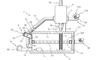
- FIG. 1 is a side sectional view of an incinerator according to an embodiment of the present invention
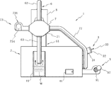
- FIG. 2 is a side view of the opposite side of the incinerator
- FIG. 3 is a rear sectional view of the incinerator
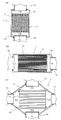
- FIG. ) Is a side sectional view of a mixed gas feeding device in the incinerator
- FIG. 4B is a plan sectional view of the device
- FIG. 4C is a front sectional view of the device
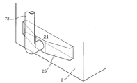
- FIG. FIG. 6 is a perspective view of a connecting portion between the mixed gas inlet pipe and the furnace body in the apparatus
- FIG. 7 is a cross-sectional view of an exhaust gas combustion cylinder in the incinerator
- FIG. 8 is in the incinerator.
- FIG. 9 is a perspective view of a heat storage section provided in the secondary combustion apparatus.
- the incinerator 1 is provided from the inside of the furnace main body 2, the incineration object charging unit 3 and the fire type charging unit 4 provided on the side wall of the furnace main body 2, and upward from the inside of the furnace main body 2.
- An exhaust gas combustion cylinder 5, an exhaust pipe 6 continuous to the exhaust gas combustion cylinder 5, a mixed gas feeding device 7 and a secondary combustion device 8 provided in the middle of the exhaust pipe 6, and the interior of the furnace body 2 are provided with a fresh air feeding device 9 and a fresh air supply device 23, and a water tank 10 provided at the end of the exhaust pipe 6.
- the furnace body 2 in the present embodiment has a substantially rectangular parallelepiped shape, but the present invention is not limited to such a shape.
- the inner wall 21 of the furnace body 2 is preferably made of a material having excellent heat resistance, such as brick and mortar, and the outer surface 22 of the furnace body 2 is pasted with a material having excellent corrosion resistance, such as a stainless steel plate. It is preferable.
- the incinerator throwing unit 3 includes a cylindrical body 31 fitted on the side wall of the furnace body 2, an outer lid 32 provided in the outer opening of the cylindrical body 31 so as to be openable and lockable, and a cylindrical body 31. And an inner lid 35 provided in the inner opening so as to be freely opened and closed. Inside the outer lid 32, a pushing plate 34 is provided for pushing the incinerated material into the furnace body 2, and the pushing plate 34 can be slid through the outer lid 32.
- the portion 33 is fixed.
- the inner lid 35 can be rotated about a shaft 36 as a rotation axis.
- By operating an operating rod 37 fixed to the inner lid 35 and rotating the inner lid 35 The inner opening of the body 31 can be opened and closed.
- the operation rod 37 is fixed with a weight 38 for easy operation.
- the fire type charging unit 4 is provided at the lower part of the side wall of the furnace body 2, and the fire type charging unit 4 is provided with a lid 41 that can be opened and closed and locked.
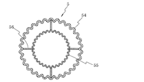
- the exhaust gas combustion cylinder 5 has a double pipe structure having an outer cylinder 54 and an inner cylinder 55, and the inner cylinder 55 extends along the outer cylinder 54 and the inner cylinder 55. It is fixed to the outer cylinder 54 by two plate-like fixing members 56.
- the inner cylinder 55 is heated by the combustion heat in the furnace body 2 at the time of combustion, so that the exhaust gas combustion cylinder can be maintained at a higher temperature. it can.
- Concavities and convexities are formed on the outer and inner surfaces of the outer cylinder 54 and the inner cylinder 55. By forming such irregularities, the contact area with the internal space of the furnace body 2 and the contact area with the exhaust gas are increased, so that the combustion heat in the furnace body 2 is efficiently transmitted to the exhaust gas, and the exhaust gas is transmitted. It can be burned effectively.
- the lower end portion of the exhaust gas combustion cylinder 5 is set to a predetermined height from the inner bottom surface of the furnace body 2.
- the diameter of the exhaust gas combustion cylinder 5 is about 20 cm
- the lower end portion of the exhaust gas combustion cylinder 5 The height is preferably about 10 to 20 cm, and more preferably about 15 cm.
- a combustion cylinder protection cylinder 51 surrounding the exhaust gas combustion cylinder 5 is provided around the exhaust gas combustion cylinder 5 outside the furnace body 2.
- the combustion cylinder protection cylinder 51 is erected on the furnace body 2, and the upper portion of the combustion cylinder protection cylinder 51 is reduced in diameter upward, and is in contact with the exhaust gas combustion cylinder 5 at the upper end.
- the inner wall 53 of the combustion cylinder protection cylinder 51 is preferably made of a material having excellent heat insulation and heat resistance.
- a support member 52 that connects the combustion cylinder protection cylinder 51 and the exhaust gas combustion cylinder 5 and supports the exhaust gas combustion cylinder 5 is provided inside the combustion cylinder protection cylinder 51.
- the exhaust pipe 6 continuing to the exhaust gas combustion cylinder 5 has a base end connected to the distal end of the exhaust gas combustion cylinder 5, and is located above and secondary to the exhaust gas combustion cylinder 5.
- a third exhaust pipe 63 having an open end.
- the lower part of the third exhaust pipe 63 is located on the inner upper part of the bottomed cylindrical water tank 10 having a diameter larger than the diameter of the third exhaust pipe 63.
- the end of the exhaust pipe 63 faces the water surface of the water stored in the water tank 10.
- a secondary combustion device 8 is provided between the exhaust gas combustion cylinder 5 and the mixed gas feeding device 7.
- the first exhaust pipe 61 connecting the exhaust gas combustion cylinder 5 and the secondary combustion apparatus 8 is bent in a U shape as described above, thereby suppressing the momentum of the flame ejected from the exhaust gas combustion cylinder 5, Heat can be easily retained in the secondary combustion device 8, and efficient combustion of exhaust gas by the secondary combustion device 8 can be promoted.
- the secondary combustion apparatus 8 includes a main body 81, a fresh air supply pipe 82 provided in the main body 81, and fresh air connected to the fresh air supply pipe 82. It is comprised from the sending-in apparatus 9a.
- the main body 81 of the secondary combustion apparatus 8 in the present embodiment is cylindrical, has an exhaust introduction port 811 to which the first exhaust pipe 61 is connected at the lower end central portion, and the second upper end central portion.
- the exhaust pipe 62 is connected to an exhaust outlet.
- the fresh air supply pipe 82 is installed in the main body 81 of the secondary combustion apparatus 8 along the movement direction of the exhaust gas.
- the fresh air supply pipe 82 has a cylindrical shape in which a plurality of holes 821 are formed.
- a lower end portion of the fresh air supply pipe 82 is connected to a fresh air feeding device 9 a provided outside the main body portion 81.
- the fresh air feeding device 9a has the same configuration as the fresh air feeding device 9 described later.
- a heat storage unit 83 is provided on the exhaust inlet 811, and a flame radiating unit 84 is provided on the heat storage unit 83.
- the heat storage unit 83 is configured by stacking a plurality of channel members 831 in a grid pattern and fixing the channel members 831 to each other.
- Each channel member 831 has a U-shaped cross section, and is stacked with the opening portion facing the exhaust inlet 811 so as not to block the inflow of exhaust gas into the main body 81.
- the heat storage part 83 in this embodiment is comprised with the channel material 831 of 4x2 steps
- the flame radiating portion 84 provided on the heat storage portion 83 has a cylindrical shape with a closed upper end, and a plurality of holes 841 are formed in the side wall.
- the flame radiating portion 84 is fixed to the main body 81 of the secondary combustion device 8 by a support rod 85.
- fresh air is fed into the fresh air supply pipe 82 from the fresh air feeding device 9 a, and the main body portion of the secondary combustion device 8 is inserted into the fresh air supply pipe 82 from the plurality of holes 821.
- Fresh air can be ejected into 81.
- the fresh air is entirely blown against the exhaust gas moving in the main body 81 of the secondary combustion device 8, thereby combusting combustible exhaust gas generated in the furnace main body 2, It becomes possible to make the exhaust gas cleaner.
- the heat storage unit 83 provided in the main body 81 of the secondary combustion apparatus 8 is heated to a high temperature by the flame ejected from the exhaust gas combustion cylinder 5 and stored. Therefore, even when the flame ejected from the exhaust gas combustion cylinder 5 becomes small and the temperature in the main body 81 of the secondary combustion device 8 is likely to be lowered, the main body of the secondary combustion device 8 by the heat storage action of the heat storage unit 83.
- the inside of the part 81 can be maintained at a high temperature, and the combustion efficiency of the exhaust gas in the secondary combustion device 8 can be improved.
- the flame radiating portion 84 Since the upper end of the flame radiating portion 84 provided in the main body 81 of the secondary combustion device 8 is closed, the flame ejected from the exhaust gas combustion cylinder 5 passes through the heat accumulating portion 83 to cause secondary combustion. While blocking the passage through the main body 81 of the apparatus 8 as it is, the flame is radiated into the main body 81 of the secondary combustion apparatus 8 from the hole 841 formed in the side wall of the flame radiating section 84. In this way, the flame radiating unit 84 can heat the inside of the main body 81 of the secondary combustion device 8 to a high temperature and promote the highly efficient combustion of the exhaust gas by the secondary combustion device 8.
- the mixed gas feeding device 7 includes a main body portion 71, a mixed gas feeding pipe 72 and a fresh air feeding device 73 connected to the main body portion 71, and the main body portion 71 is fresh.
- An air intake unit 711, an exhaust introduction unit 712, an exhaust discharge unit 713, and a mixed gas discharge unit 714 are provided.
- the upper portion of the main body portion 71 is an exhaust introduction portion 712
- the lower portion of the main body portion 71 is an exhaust discharge portion 713
- one side portion of the main body portion 71 is a fresh air intake portion. 711
- the other side portion of the main body portion 71 is a mixed gas discharge portion 714.
- the second exhaust pipe 62 is connected to the exhaust introduction part 712 of the main body 71, and the third exhaust pipe 63 is connected to the exhaust discharge part 713. Further, a fresh air inlet device 73 is connected to the fresh air intake section 711, and one end of a mixed gas inlet pipe 72 is connected to the mixed gas discharge section 714.
- the diameters of the second exhaust pipe 62, the third exhaust pipe 63, and the mixed gas inlet pipe 72 are substantially the same. Therefore, since the 2nd exhaust pipe 62, the 3rd exhaust pipe 63, and the mixed gas inflow pipe 72 can use the pipe member of the same diameter, the manufacturing cost of this incinerator 1 can be reduced. .
- the other end of the mixed gas inlet pipe 72 is connected to the lower part of the side surface of the furnace body 2.
- the lower part of the side surface of the furnace body 2 in the present embodiment has a rectangular opening 24 that is longer in the horizontal direction than in the vertical direction, and one end of the mixed gas inlet pipe 72 is connected to the connection member 25. Connected to the opening 24.
- the connecting member 25 has an octahedral shape in which the connection surface with the mixed gas inlet pipe 72 and the connection surface with the opening 24 face each other (however, the connection surface with the opening 24 is And a shape in which the rectangular cross section gradually increases horizontally from the connection surface with the mixed gas inlet pipe 72 toward the connection surface with the opening 24. It has become.
- a mixed gas containing high-temperature oxygen can be fed into the furnace body 2 so as to spread from the lower side of the side surface of the furnace body 2 to a wide range of the furnace body 2, and as a result, higher combustion is achieved.
- the incinerated object can be burned with efficiency.
- the air intake unit 731 of the fresh air input device 73 connected to the fresh air intake unit 711 of the mixed gas input device 7 adjusts the air intake amount of the turbine 732 driven by the motor 734 and the turbine 732. And an adjustment lid 733 that can be operated, and by driving a turbine 732, fresh air can be introduced into the mixed gas feeding device 7.
- a plurality of partition members 75 are provided at a predetermined interval inside the main body 71.
- the partition member 75 is a plate-shaped member formed in the side view waveform.
- adjacent partition members 75 are connected by welding a U-shaped connecting member 76, and the connection by the connecting member 76 is repeated.
- the some partition member 75 is arranged in parallel by the horizontal direction.
- the partition members 75 located at both ends come into contact with the inner side wall 715 of the main body 71, so that the plurality of partition members 75 arranged in parallel are fixed in the main body 71.
- the present invention is not limited to this, and the number of the partition members 75 shown in FIG. 4 may be increased or decreased, and the partition members 75 are juxtaposed by penetrating the rod-like connecting members through the partition members 75. May be.
- the plurality of partition members 75 are provided in the main body 71 at predetermined intervals, so that a plurality of gas flow paths are formed in the direction from the fresh air intake portion 711 toward the mixed gas discharge portion 714.
- a plurality of gas flow paths are formed in a direction from the exhaust introduction part 712 toward the exhaust discharge part 713, and fresh air taken in from the fresh air intake part 711 and exhaust gas taken in from the exhaust introduction part 712 are Crossing in the gas flow path, mixed gas is generated.
- an exhaust amount adjusting plate 74 is provided at the opening of the third exhaust pipe 63 in the exhaust discharge portion 713 of the gas delivery device 7.
- the displacement adjustment plate 74 has a circular plate shape, and a plurality of holes 741 are formed.
- the displacement adjustment plate 74 is not limited to a circular plate shape, and may be a rectangular plate shape or a square plate shape. Further, the number of holes 741 formed in the exhaust amount adjustment plate 74 may be one.
- the hole 741 formed in the exhaust amount adjusting plate 74 is configured such that the opening area of the exhaust discharge part 713 is 40 to 60%, particularly 45 to 55%, more preferably around 50% of the opening area of the mixed gas discharge part 714. It is preferable to form, and thereby the combustion efficiency in the incinerator 1 can be further increased.
- the opening area of the exhaust discharge portion 713 is 40 to 60% of the opening area of the exhaust introduction portion 712, in particular 45 to 55%, and even around 50%.
- the combustion efficiency in the incinerator 1 can be further increased.
- exhaust discharge part 713 of the main body 71 in the mixed gas feeding device 7 is a part of the main body 71 closer to the third exhaust pipe 63 than the partition member 75 (part where the mixed gas is generated).
- the exhaust amount adjustment plate 74 may not be provided in the opening of the third exhaust pipe 63, and may be provided in any position between the partition member 75 and the third exhaust pipe 63. Further, it may be provided inside the third exhaust pipe 63.
- the “opening area of the exhaust discharge section 713” refers to the opening area (total area of the holes 741) of the portion where the exhaust amount adjustment plate 74 is provided.
- the opening area of the part to which the exhaust pipe 63 is connected is assumed to be. That is, in the present invention, the exhaust amount adjustment plate 74 is not necessarily provided, and in order to make the opening area of the exhaust discharge part 713 smaller than the opening area of the mixed gas discharge part 714 (and the exhaust introduction part 712), for example,
- the diameter of the third exhaust pipe 63 may be smaller than the mixed gas inlet pipe 72 (and the second exhaust pipe 62).
- the “opening area of the mixed gas discharge part 714” means that unless another member (a member such as the exhaust amount adjusting plate 74) is provided between the partition member 75 and the mixed gas inlet pipe 72.
- the opening area of the part to which the mixed gas inlet pipe 72 is connected shall be said.
- the “opening area of the exhaust introduction part 712” is determined unless any other member (a member such as the exhaust amount adjustment plate 74) is provided between the partition member 75 and the second exhaust pipe 62. The opening area of the portion where the second exhaust pipe 62 is connected is assumed.
- the fresh air feeding device 9 includes a turbine 91 driven by a motor 93 and an air intake of the turbine 91 in the same manner as the air intake unit 731 of the fresh air feeding device 73 provided in the mixed gas feeding device 7.
- An adjustment lid 92 capable of adjusting the amount is provided, and fresh air can be introduced into the furnace body 2 by driving the turbine 91.
- the fresh air fed from the fresh air feeding device 9 can compensate for oxygen that is not sufficient in the mixed gas fed from the mixed gas feeding device 7.
- the ratio adjustment between the flow rate of the mixed gas fed from the mixed gas feed device 7 and the flow rate of the fresh air sent from the fresh air feed device 9 is provided in the air intake portion 731 of the mixed gas feed device 7.
- the adjustment lid 733 and the adjustment lid 92 provided in the fresh air feeding device 9 can adjust the air intake amounts of the turbine 732 and the turbine 91, respectively.
- the fresh air supply device 23 is connected to a fresh air supply pipe 231 provided inside the furnace body 2 and a fresh air supply pipe 231, and is connected to the outside of the furnace body 2. It comprises a fresh air feeding device 9b provided.
- the fresh air feeding device 9 b has the same configuration as the fresh air feeding device 9.
- the fresh air supply pipe 231 has an annular shape in plan view as a whole, has a rectangular cross section as the pipe itself, and is attached to the middle stage of the inner peripheral wall of the furnace body 2.
- a plurality of holes 232 are formed in the side wall of the fresh air supply pipe 231 on the inner side of the furnace body 2.
- fresh air is supplied from the fresh air supply device 9 b into the fresh air supply tube 231, and the plurality of holes 232 of the fresh air supply tube 231 are directed inward of the furnace body 2. Since fresh air can be ejected, air is evenly supplied into the furnace body 2 and effectively supplements oxygen that is not sufficient with the air fed from the mixed gas feeding device 7 and the fresh air feeding device 9. be able to.
- the outer lid 32 is closed and locked.
- the operation rod 37 of the incinerator throwing portion 3 is pulled forward (left side in FIG. 1) to open the inner lid 35 and the gripping portion 33 is pushed toward the outer lid 32 to push the pushing plate 34 of the furnace body 2.
- the grip portion 33 is pulled back, and the operation rod 37 is pushed down (to the right side in FIG. 1) to close the inner lid 35.
- the operation of charging the incinerated material is repeated.
- the kind of the incinerated material is not particularly limited, but the one containing moisture can prevent the fire from being generated instantaneously and generating smoke.
- Examples of the incinerator containing moisture include raw garbage, used medical or infant diapers, wet wood, and the like.
- the incineration object to which the fire of the fire type has burned out is continuously burned by oxygen supplied from the fresh air feeding device 9 and the mixed gas feeding device 7.
- the exhaust gas combustion cylinder 5 is heated to a high temperature by the combustion heat of the incinerated material.
- the exhaust gas generated by the combustion of the incinerated material rises in the exhaust gas combustion cylinder 5 by the updraft.
- the air supplied from the fresh air feeding device 9 and the mixed gas feeding device 7 is also the updraft.
- the exhaust gas combustion cylinder 5 is raised.
- the exhaust gas combustion cylinder 5 is heated to a high temperature, the exhaust gas rising in the exhaust gas combustion cylinder 5 is burned in the presence of air (oxygen).
- Exhaust gas that has been heated in the exhaust gas combustion cylinder 5 to a high temperature flows into the secondary combustion device 8 from the first exhaust pipe 61 and undergoes secondary combustion. Thereby, the combustible exhaust gas generated in the furnace body 2 is combusted, and the exhaust gas becomes cleaner.
- the secondary combustion exhaust gas flows from the second exhaust pipe 62 into the main body 71 of the mixed gas feeding device 7, and from the exhaust introduction portion 712 to the exhaust discharge portion 713 (from top to bottom in FIG. 4A). Try to secure the flow path in the direction of.
- fresh air that has flowed from the air intake portion 731 of the fresh air inlet device 73 into the main body portion 71 of the mixed gas inlet device 7 flows from the fresh air inlet portion 711 toward the mixed gas discharge portion 714 (FIG. 4B). ) To secure the flow path in the direction from left to right).
- the exhaust gas flowing into the main body 71 and the fresh air intersect along the gap between the partition members 75, and a mixed gas is generated inside the main body 71.
- the partition member 75 and forming a plurality of narrow flow paths the exhaust gas and the fresh air do not diffuse when intersecting, and are mixed substantially uniformly inside the main body 71.
- the mixed gas produced by mixing very hot exhaust gas and fresh air contains oxygen and has a high temperature.
- the generated mixed gas is discharged from the exhaust discharge unit 713 and the mixed gas discharge unit 714.
- the exhaust amount adjusting plate 74 is provided at the opening of the exhaust discharge unit 713, thereby making the opening area of the exhaust discharge unit 713 smaller than the opening area of the mixed gas discharge unit 714. Therefore, the amount of the mixed gas discharged from the exhaust discharge unit 713 is suppressed.
- the amount of the mixed gas discharged from the mixed gas discharge unit 714 and fed into the furnace body 2 through the mixed gas feed pipe 72 increases.
- the mixed gas contains oxygen and has a high temperature as described above, the combustion temperature in the furnace body 2 rises in a short time and the combustion efficiency is dramatically improved by feeding the mixed gas.
- it usually takes about 6 hours to reach 800 ° C. in an ordinary incinerator using wood as an incinerator and using oil as fuel. Can reach about 800 ° C. in about 20 to 30 minutes without using fuel.
- the incinerated material burns in the furnace body 2 with high combustion efficiency, and the exhaust gas generated by the combustion burns in the exhaust gas combustion cylinder 5 and also burns in the secondary combustion device 8.
- the amount of soot and ash generated by incomplete combustion is extremely small. Further, since the exhaust gas circulates through the mixed gas feeding device and is reburned, cleaner exhaust gas is discharged.
- the third exhaust pipe 63 faces the water surface of the water tank 10, even if ash is present in the exhaust gas discharged from the third exhaust pipe 63, the ash is in the water. Captured and prevented from spreading into the atmosphere. In this way, clean exhaust gas is discharged into the atmosphere.
- the terminal part of the 3rd exhaust pipe 63 may be provided with the normal form, without facing the water surface of the water of the water tank 10, and is discharged
- the exhaust gas may be showered with water to prevent ash in the exhaust gas from diffusing into the atmosphere.
- the combustion efficiency is high, the discharged gas is clean and can prevent damage caused by soot and ash, and the structure is simple, the manufacturing cost is low, and the compactness can be achieved (for example, installation) area it is possible to 2m 2 below.) Therefore, it can be utilized by installing company, hospital, easily in a factory or the like.
- the incinerator according to the present invention is useful for incinerating paper scraps, garbage, used diapers, wood, etc. discharged from homes, companies, hospitals, factories and the like.
- Inner cylinder 56 Fixed member 6 ... Exhaust pipe 61 ... 1st exhaust Pipe 62 ... Second exhaust pipe 63 ... Third exhaust pipe 7 ... Mixed gas feeding device 71 ... Main body part 711 ... Fresh air intake part 712 ... Exhaust gas introduction part 713 ... Exhaust gas discharge part 714 ... Mixed gas discharge part 715 ... Inner side wall 72 ... Mixed gas inlet pipe 73 ... Fresh air inlet device 731 ... Air inlet 732 ... Turbine 733 ... Adjustment lid 734 ... Motor 74 ... Exhaust amount adjustment plate 741 ... Hole 75 ... Partitioning member 76 ... Connecting member 8 Secondary combustion system 81 ... main body portion 811 ... exhaust gas introduction port 82 ...
- fresh air supply fresh air supply pipe
- Hole 83 Heat storage part 831 ... Channel material 84 ... Flame radiation part 841 ... Hole 85 . Support rods 9, 9a, 9b ... Fresh air feeding device 91 ... Turbine 92 ... Adjustment lid 93 ... Motor 10 ... Water tank
Landscapes
- Engineering & Computer Science (AREA)
- Mechanical Engineering (AREA)
- General Engineering & Computer Science (AREA)
- Incineration Of Waste (AREA)
Abstract
【課題】 燃焼効率が高く、不完全燃焼により発生する煤煙、および灰の量が極めて少ない焼却炉を提供する。 【解決手段】 被焼却物投入部3を有する炉本体2に対し、少なくとも前記炉本体2の内部に位置する部分を有する排気ガス燃焼筒5を設け、その排気ガス燃焼筒5には、途中に混合ガス送入装置7を有する排気管6を連結する。その混合ガス送入装置7は、排気ガスおよびフレッシュエアを混合して混合ガスを生成し、炉本体2に送り入れる。
Description
本発明は、家庭、企業、病院、工場等から排出されるゴミなどを焼却処理する焼却炉に関するものである。
従来より、家庭、企業、病院、工場等から排出される紙屑、生ゴミ、使用済みおむつ、木材などを焼却するために、種々の焼却炉が提案されている。しかしながら、いずれの焼却炉においても、簡易な構造でゴミを完全燃焼させることができず、不完全燃焼により煤煙が発生するという問題や、焼却後に残った灰を如何にして処分するかという問題があった。
焼却炉の燃焼効率が高まれば煤煙や灰を極力少なくすることができる。燃焼効率を高める手段としては、フレッシュエアを焼却炉に供給して炉内の酸素濃度を上げること(例えば特許文献1)、さらにそのフレッシュエアを加熱してから供給することにより炉内の温度を高温に維持すること(例えば特許文献2)、燃焼ガスを再循環させて炉内の温度を高温に維持すること(例えば特許文献3)などが提案されている。
しかしながら、特許文献1において開示されたように、炉内の酸素濃度を上げるためにフレッシュエアを焼却炉に供給すると、焼却炉内の温度が下がるため、燃焼効率を高めるには限界があった。その問題点を解決するべく、特許文献2においては、供給前に熱交換器にてフレッシュエアを加熱して焼却炉内の温度を下げない技術が開示されているが、当該熱交換器によって加熱した場合、フレッシュエアの温度上昇には限界があるため、ゴミを完全燃焼させるまでにはまだ改善の余地がある。
また、特許文献3において開示されたように、燃焼ガスを再循環させると炉内の温度を高温に維持することができるが、焼却炉内の酸素濃度が下がってしまう。そのため、燃焼に際して炉内に酸素を補給してやる必要があるが、酸素を補給することにより焼却炉内の温度が低下してしまう問題がある。
本発明は、このような実情に鑑みてなされたものであり、燃焼効率が高く、不完全燃焼により発生する煤煙、および灰の量が極めて少ない焼却炉を提供することを目的とする。
上記目的を達成するために、本発明は、被焼却物投入部を有する炉本体と、少なくとも前記炉本体の内部に位置する部分を有する排気ガス燃焼筒と、前記排気ガス燃焼筒に連続する排気管と、前記排気管の途中に設けられた、排気ガスおよびフレッシュエアを混合して混合ガスを生成し前記炉本体に送り入れることのできる混合ガス送入装置とを備えた焼却炉を提供する(発明1)。
上記発明(発明1)においては、被焼却物投入部から炉本体内に投入された被焼却物が燃焼すると、被焼却物の燃焼熱によって排気ガス燃焼筒が高温に加熱される。被焼却物の燃焼によって発生した排気ガスは、上昇気流によって排気ガス燃焼筒内を上昇し、同様に、混合ガス送入装置から供給された混合ガスも上昇気流によって排気ガス燃焼筒内を上昇する。ここで、排気ガス燃焼筒は高温に加熱されているため、排気ガス燃焼筒内を上昇する排気ガスは、酸素を含んでいる混合ガスの存在下で燃焼することになる。
排気ガス燃焼筒で燃焼して高温になった排気ガスは、排気管を通じて混合ガス送入装置に流入し、当該装置内でフレッシュエアと混合される。生成された混合ガスの一部は当該装置から炉本体に送り込まれ、残りの混合ガスは排気管を通じて排出される。
混合ガス送入装置から炉本体に送り込まれた混合ガスは高温であるため、かかる混合ガスの送入によって、炉本体内の燃焼温度は短時間で上昇し、炉本体内は高温に維持される。同時に、混合ガスにはフレッシュエアが混合されているため、高温の酸素が炉本体内に補給されることになる。その結果、被焼却物は炉本体内において高い燃焼効率で燃焼するとともに、燃焼で発生した排気ガスは排気ガス燃焼筒内でさらに燃焼するため、不完全燃焼により発生する煤煙や灰の量は極めて少なくなる。
上記発明(発明1)において、前記混合ガス送入装置は、フレッシュエア取込部、排気導入部、排気排出部および混合ガス排出部とを有する本体部と、前記混合ガス排出部に接続されて前記混合ガスを前記炉本体に送り入れる混合ガス送入管とを備えており、前記混合ガス排出部の開口面積よりも前記排気排出部の開口面積が小さいことが好ましく(発明2)、さらに、前記排気導入部の開口面積よりも前記排気排出部の開口面積が小さいことが好ましい(発明3)。
上記発明(発明1)においては、フレッシュエア取込部から取り込まれたフレッシュエアと排気導入部から取り込まれた排気ガスとが、前記混合ガス送入装置本体部内において混合され、混合ガスが生成される。生成された混合ガスは混合ガス送入管を通じて炉本体に送り込まれる。上記発明(発明2)によれば、混合ガス排出部の開口面積よりも排気排出部の開口面積が小さいことにより、排気する混合ガスの量よりも炉本体へ送り込む混合ガスの量が多くなる。すなわち、炉本体に送り込む高温の混合ガスが増えることとなるため、炉本体の内部温度をより高温にすることができ、さらに高い燃焼効率で被焼却物を燃焼させることができる。さらに、上記発明(発明3)によれば、排気導入部の開口面積よりも排気排出部の開口面積が小さいことにより、排気する混合ガスの量を抑制し、結果的に炉本体に送り込む混合ガスの量をより多くすることができる。
上記発明(発明2,3)においては、前記排気排出部に、孔が形成された排気量調整板が設けられており、もって、前記混合ガス排出部の開口面積よりも前記排気排出部の開口面積を小さくしていることが好ましい(発明4)。また、上記発明(発明2,3)において、前記排気排出部に接続される前記排気管の口径と前記混合ガス排出部に接続される前記混合ガス送入管の口径とが実質的に同じである場合においては、前記排気排出部における前記排気管の接続部または前記排気管の開口部に、孔が形成された排気量調整板が設けられており、もって、前記混合ガス排出部の開口面積よりも前記排気排出部の開口面積を小さくしていることが好ましい(発明5)。さらに、上記発明(発明5)において、前記排気導入部に接続される前記排気管の口径も、前記排気排出部に接続される前記排気管および前記混合ガス排出部に接続される前記混合ガス送入管の口径と実質的に同じであってもよい(発明6)。
上記発明(発明4,5)によれば、孔が形成された排気量調整板を設けるだけで、排気排出部の開口面積を混合ガス排出部の開口面積よりも簡単に小さくすることができる。また、排気量調整板に形成する孔の大きさや数を変更すること(排気量調整板を交換すること)で、両者の面積比を容易に変更することができる。さらに、上記発明(発明5,6)によれば、排気管および混合ガス送入管は同じ径の管部材を使用することができるため、焼却炉の製造コストを低減することができる。
上記発明(発明2~6)において、前記排気排出部の開口面積は、前記混合ガス排出部の開口面積の40~60%であることが好ましく(発明7)、特に45~55%、さらには50%前後であることが好ましい。
上記発明(発明2~7)において、前記混合ガス送入装置は、前記本体部の前記フレッシュエア取込部に接続された、フレッシュエアを強制的に送り込むフレッシュエア送入装置を備えているのが好ましい(発明8)。
上記発明(発明8)によれば、フレッシュエア送入装置を備えることにより、本体部において、所望の量のフレッシュエアを排気ガスと混合することができる。また、フレッシュエアが強制的に送り込まれることから、自然吸気の場合と比較して、フレッシュエアが排気ガスと容易に混合し、炉本体に送り込まれる混合ガス中に安定してフレッシュエアが含まれるようになる。その結果、混合ガス中の酸素濃度が上がるため、さらに高い燃焼効率で被焼却物を燃焼させることができる。
上記発明(発明8)において、前記本体部においては、前記フレッシュエア取込部と前記混合ガス排出部とが正対し、前記排気導入部と前記排気排出部とが正対するように、前記フレッシュエア取込部、前記排気導入部、前記排気排出部および前記混合ガス排出部が形成され、かつ、前記フレッシュエア取込部から取り込まれたフレッシュエアと前記排気導入部から取り込まれた排気ガスとが交差するように、前記フレッシュエア取込部と前記排気導入部とが形成されていることが好ましい(発明9)。
上記発明(発明9)によれば、フレッシュエア取込部から取り込まれたフレッシュエアが混合ガス排出部方向に、排気導入部から取り込まれた排気ガスが排気排出部方向に流路を確保しようとし、フレッシュエアと排気ガスとが本体部内で交差する結果、フレッシュエアと排気ガスとを略均一に混合することができる。
上記発明(発明9)において、前記本体部は、前記フレッシュエア取込部から前記混合ガス排出部に向かう方向に複数のガス流路が形成され、かつ、前記排気導入部から前記排気排出部に向かう方向に複数のガス流路が形成されるように、複数の仕切部材を内部に備えていることが好ましい(発明10)。
上記発明(発明10)によれば、フレッシュエアと排気ガスとが交差する際に、両者が混合されずに拡散してしまうことを仕切部材の存在により防ぐことができるため、より均質な混合ガスを生成することができる。
上記発明(発明2~10)において、前記混合ガス送入管は、前記炉本体の側面下部に設けられた開口部に接続されており、前記開口部は、縦方向よりも横方向に長い形状となっていることが好ましい(発明11)。
上記発明(発明11)によれば、高温の酸素が含まれる混合ガスを、炉本体側面下部から炉本体の広い範囲に行き渡らせるように炉本体に送り込むことができるため、より高い燃焼効率で被焼却物を燃焼させることができる。
上記発明(発明1~11)において、排気導入口および排気排出口を有する本体部、前記本体部内にフレッシュエアを供給することのできるフレッシュエア供給部、ならびに前記排気ガス燃焼筒から噴き出してくる炎を前記本体部内に放射することのできる火炎放射部を有する二次燃焼装置を備えていることが好ましい(発明12)。
前記二次燃焼装置を備えた場合には、前記排気ガス燃焼筒は、前記炉本体から鉛直方向に延びており、前記排気管は、一端が前記排気ガス燃焼筒に連続し、他端が前記二次燃焼装置本体部の排気導入口に接続され、U字状に屈曲している部分を少なくとも2つ有する第1の排気管と、一端が前記二次燃焼装置本体部の排気排出口に接続され、他端が前記混合ガス送入装置本体部の排気導入部に接続された第2の排気管と、前記混合ガス送入装置本体部の排気排出部に接続された第3の排気管とを備えたものとするのが好ましい(発明13)。
上記発明(発明1~13)において、前記排気ガス燃焼筒は、二重管構造となっていることが好ましい(発明14)。
上記発明(発明14)によれば、排気ガス燃焼筒内をより高温に維持することができるため、排気ガスを排気ガス燃焼筒内で燃焼する際の燃焼効率が高まることになる。
以上説明したように、本発明の焼却炉によれば、高い燃焼効率で被焼却物を燃焼させることができ、煤煙および灰の発生を抑制することができる。
以下、本発明の実施形態を図面に基づいて説明する。
図1は本発明の一実施形態に係る焼却炉の側面一部断面図、図2は同焼却炉の反対側の側面図、図3は同焼却炉の背面一部断面図、図4(a)は同焼却炉における混合ガス送入装置の側面断面図、図4(b)は同装置の平面断面図、図4(c)は同装置の正面断面図、図5は同装置における排気量調整板の斜視図、図6は同装置における混合ガス送入管と炉本体との接続部分の斜視図、図7は同焼却炉における排気ガス燃焼筒の断面図、図8は同焼却炉における二次燃焼装置の断面図、図9は同装置に設けられた蓄熱部の斜視図である。
図1は本発明の一実施形態に係る焼却炉の側面一部断面図、図2は同焼却炉の反対側の側面図、図3は同焼却炉の背面一部断面図、図4(a)は同焼却炉における混合ガス送入装置の側面断面図、図4(b)は同装置の平面断面図、図4(c)は同装置の正面断面図、図5は同装置における排気量調整板の斜視図、図6は同装置における混合ガス送入管と炉本体との接続部分の斜視図、図7は同焼却炉における排気ガス燃焼筒の断面図、図8は同焼却炉における二次燃焼装置の断面図、図9は同装置に設けられた蓄熱部の斜視図である。
本実施形態による焼却炉1は、炉本体2と、炉本体2の側壁に設けられた被焼却物投入部3および火種投入部4と、炉本体2の内部から外部上方に向かって設けられた排気ガス燃焼筒5と、排気ガス燃焼筒5に連続している排気管6と、排気管6の途中に設けられた混合ガス送入装置7および二次燃焼装置8と、炉本体2の内部に連通しているフレッシュエア送入装置9およびフレッシュエア供給装置23と、排気管6の末端部に設けられた水槽10とを備えている。
本実施形態における炉本体2は、略直方体の形状を有するが、本発明はかかる形状に限定されるものではない。炉本体2の内壁21は、耐熱性に優れた材料、例えばレンガおよびモルタル等から構成するのが好ましく、炉本体2の外面22には、耐腐食性に優れた材料、例えばステンレス鋼板等を張り付けるのが好ましい。
被焼却物投入部3は、炉本体2の側壁に嵌設された筒体31と、筒体31の外側開口部に開閉自在かつロック可能に設けられた外側蓋体32と、筒体31の内側開口部に開閉自在に設けられた内側蓋体35とを備えている。外側蓋体32の内側には、投入した被焼却物を炉本体2内に押し込むための押込板34が設けられており、押込板34には、外側蓋体32を貫通し摺動し得る把持部33が固着している。内側蓋体35は、軸36を回動軸として回動し得るようになっており、内側蓋体35に固着された操作杆37を操作して内側蓋体35を回動させることにより、筒体31の内側開口部を開閉することができる。なお、操作杆37には、操作を楽に行うための錘38が固定されている。
火種投入部4は、炉本体2の側壁下部に設けられおり、この火種投入部4には蓋体41が開閉自在かつロック可能に設けられている。
図7に示すように、排気ガス燃焼筒5は外筒54および内筒55を有する二重管構造となっており、内筒55は、外筒54および内筒55に沿って延在する4つの板状の固定部材56により外筒54に固定されている。このような二重管構造とすることにより、燃焼時には外筒54のみならず内筒55も炉本体2内の燃焼熱により高温になるため、排気ガス燃焼筒内をより高温に維持することができる。
外筒54および内筒55の外面および内面には凹凸が形成されている。このような凹凸を形成することにより、炉本体2の内部空間との接触面積および排気ガスとの接触面積が増加するため、炉本体2内の燃焼熱を排気ガスに効率良く伝え、排気ガスを効果的に燃焼させることができる。
排気ガス燃焼筒5の下端部は、炉本体2の内部底面から所定の高さに設定されており、例えば、排気ガス燃焼筒5の直径が20cm程度のときには、排気ガス燃焼筒5の下端部の高さは、10~20cm程度であるのが好ましく、特に15cm程度であるのが好ましい。
炉本体2の外部における排気ガス燃焼筒5の周囲には、排気ガス燃焼筒5を囲繞する燃焼筒保護筒51が設けられている。燃焼筒保護筒51は炉本体2上に立設しており、燃焼筒保護筒51の上部は上方に向かって縮径しており、上端において排気ガス燃焼筒5に接している。燃焼筒保護筒51の内壁53は、断熱性および耐熱性に優れた材料から構成するのが好ましい。燃焼筒保護筒51の内部には、燃焼筒保護筒51と排気ガス燃焼筒5とを連結し、排気ガス燃焼筒5を支持する支持部材52が設けられている。
図3に示すように、排気ガス燃焼筒5に連続している排気管6は、基端部が排気ガス燃焼筒5の先端部に接続しており、排気ガス燃焼筒5の上方および二次燃焼装置8の下方においてU字状に屈曲し、先端部が二次燃焼装置8の下部に接続している第1の排気管61と、基端部が二次燃焼装置8の上部に接続しており、先端部が混合ガス送入装置7の上部に接続している略コの字状の第2の排気管62と、基端部が混合ガス送入装置7の下部に接続しており、先端部が開口している第3の排気管63とからなる。
図2に示すように、第3の排気管63の下部は、第3の排気管63の直径よりも大きい直径を有する有底円筒状の水槽10の内側上部に位置しており、第3の排気管63の末端部は、水槽10に入れられた水の水面に対向している。
排気ガス燃焼筒5と混合ガス送入装置7との間には二次燃焼装置8が設けられている。排気ガス燃焼筒5と二次燃焼装置8をつなぐ第1の排気管61は、前述のようにU字状に屈曲しており、それにより排気ガス燃焼筒5から噴き出す炎の勢いを抑えて、熱を二次燃焼装置8内に滞留しやすくし、二次燃焼装置8による排気ガスの効率良い燃焼を促すことができる。
図3および図8に示すように、二次燃焼装置8は、本体部81と、本体部81の中に設けられたフレッシュエア供給管82と、フレッシュエア供給管82に接続しているフレッシュエア送入装置9aとから構成される。
本実施形態における二次燃焼装置8の本体部81は円筒状となっており、その下端中央部に第1の排気管61が接続される排気導入口811を有し、上端中央部に第2の排気管62が接続される排気排出口を有する。
フレッシュエア供給管82は、二次燃焼装置8の本体部81内において排気ガスの移動方向に沿って設置されており、本実施形態では複数の孔821が形成された円筒状となっている。このフレッシュエア供給管82の下端部は、本体部81の外部に設けられたフレッシュエア送入装置9aに接続されている。フレッシュエア送入装置9aは、後述するフレッシュエア送入装置9と同様の構成を有する。
二次燃焼装置8の本体部81中、排気導入口811の上には蓄熱部83が設けられており、蓄熱部83の上には火炎放射部84が設けられている。図9に示すように、蓄熱部83は、複数のチャンネル材831を井桁状に積み、それぞれのチャンネル材831を互いに固定することにより構成されている。各チャンネル材831は断面コの字の形状を有し、排気ガスの本体部81内への流入を遮らないように、それぞれ開口部を排気導入口811側にして積まれている。なお、本実施形態における蓄熱部83は、4本×2段のチャンネル材831で構成されているが、本発明はこれに限定されるものではない。
蓄熱部83の上に設けられた火炎放射部84は、図9に示すように、上端が閉塞された円筒状の形状を有し、その側壁には複数の孔841が形成されている。この火炎放射部84は、支持杆85によって二次燃焼装置8の本体部81に固定されている。
上記二次燃焼装置8によれば、フレッシュエア送入装置9aからフレッシュエア供給管82内にフレッシュエアを送入し、フレッシュエア供給管82の複数の孔821から二次燃焼装置8の本体部81内にフレッシュエアを噴出することができる。そのフレッシュエアは、二次燃焼装置8の本体部81内を移動している排気ガスに対して全体的に吹き付けられ、これにより、炉本体2内で発生した燃焼可能な排気ガスを燃焼させ、排気ガスをよりクリーンなものにすることが可能となる。
二次燃焼装置8の本体部81内に設けられた蓄熱部83は、排気ガス燃焼筒5から噴き出してくる炎によって高温に加熱され、蓄熱される。したがって、排気ガス燃焼筒5から噴き出してくる炎が小さくなり、二次燃焼装置8の本体部81内の温度が低くなりそうなときでも、蓄熱部83の蓄熱作用により二次燃焼装置8の本体部81内を高温に維持し、二次燃焼装置8における排気ガスの燃焼効率を向上させることができる。
二次燃焼装置8の本体部81内に設けられた火炎放射部84は、その上端が閉塞されているため、排気ガス燃焼筒5から噴き出してきた炎が蓄熱部83をすり抜けて、二次燃焼装置8の本体部81内をそのまま通過することを遮るとともに、その炎を火炎放射部84の側壁に形成された孔841から二次燃焼装置8の本体部81内に放射する。このようにして、火炎放射部84は、二次燃焼装置8の本体部81内を高温にし、二次燃焼装置8による排気ガスの高効率な燃焼を促すことができる。
混合ガス送入装置7は、図4に示すように、本体部71と、本体部71に接続された混合ガス送入管72およびフレッシュエア送入装置73とから構成され、本体部71はフレッシュエア取込部711、排気導入部712、排気排出部713および混合ガス排出部714を備えている。本実施形態においては、本体部71の上部が排気導入部712となっており、本体部71の下部が排気排出部713となっており、本体部71の一方の側部がフレッシュエア取込部711となっており、本体部71の他方の側部が混合ガス排出部714となっている。
本体部71の排気導入部712には第2の排気管62が、排気排出部713には第3の排気管63が接続している。さらに、フレッシュエア取込部711にはフレッシュエア送入装置73が、混合ガス排出部714には混合ガス送入管72の一端が接続している。
本実施形態では、第2の排気管62、第3の排気管63および混合ガス送入管72の各口径は、実質的に同じとなっている。これにより、第2の排気管62、第3の排気管63および混合ガス送入管72は同じ径の管部材を使用することができるため、本焼却炉1の製造コストを低減することができる。
図1に示すように、混合ガス送入管72の他端は炉本体2の側面下部に接続している。本実施形態における炉本体2の側面下部は、図6に示すように、縦方向よりも横方向に長い矩形の開口部24を有し、混合ガス送入管72の一端が接続部材25を介して当該開口部24に接続している。
接続部材25は、図6に示すように、混合ガス送入管72との接続面と開口部24との接続面とが正対している八面体形状(ただし、開口部24との接続面は仮想面であり、実際は開口している)を有しており、混合ガス送入管72との接続面から開口部24との接続面に向かって、矩形の断面が横長に漸次大きくなる形状となっている。
上記のような構造により、高温の酸素が含まれる混合ガスを、炉本体2の側面下部から炉本体2の広い範囲に行き渡らせるように炉本体2に送り込むことができ、その結果、より高い燃焼効率で被焼却物を燃焼させることができる。
混合ガス送入装置7のフレッシュエア取込部711に接続しているフレッシュエア送入装置73のエア取入部731は、モータ734によって駆動されるタービン732と、タービン732のエア取入量を調節することのできる調節蓋733とを備えており、タービン732を駆動することによって、フレッシュエアを混合ガス送入装置7に導入することができるようになっている。
上記混合ガス送入装置7においては、本体部71の内部に、複数の仕切部材75が所定の間隔で設けられている。本実施形態においては、図4(a)に示すように、仕切部材75は側面視波形に形成された板状の部材である。また、図4(a)および図4(b)に示すように、隣り合った仕切部材75は、U字状の連結部材76が溶接されることにより連結され、この連結部材76による連結を繰り返すことにより、複数の仕切部材75が横方向に並設されている。さらに、両端に位置する仕切部材75が本体部71の内部側壁715に接触することにより、並設された複数の仕切部材75が本体部71内に固定されている。なお、本発明はこれに限定されるものではなく、図4に示す仕切部材75の数は増減してもよいし、棒状の連結部材を仕切部材75に貫通させることによって仕切部材75を並設してもよい。
上記のように本体部71の内部に、複数の仕切部材75が所定の間隔で設けられることで、フレッシュエア取込部711から混合ガス排出部714に向かう方向に複数のガス流路が形成され、かつ、排気導入部712から排気排出部713に向かう方向に複数のガス流路が形成され、フレッシュエア取込部711から取り込まれたフレッシュエアと排気導入部712から取り込まれた排気ガスとが当該ガス流路において交差し、混合ガスが生成される。
本実施形態では、混合ガス排出部714および排気導入部712の開口面積よりも排気排出部713の開口面積を小さくするために、図4(a)および図4(c)に示すように、混合ガス送入装置7の排気排出部713において、第3の排気管63の開口部には排気量調整板74が設けられている。本実施形態においては、図5に示すように、排気量調整板74は円形板状であり、複数の孔741が形成されている。なお、排気量調整板74は円形板状に限定されるものではなく、長方形板状や正方形板状でも構わない。また、排気量調整板74に形成される孔741は一つでも構わない。
排気量調整板74に形成される孔741は、排気排出部713の開口面積が混合ガス排出部714の開口面積の40~60%、特に45~55%、さらには50%前後となるように形成することが好ましく、これにより、本焼却炉1における燃焼効率をより高めることができる。
併せて、排気量調整板74に形成される孔741は、排気排出部713の開口面積が排気導入部712の開口面積の40~60%、特に45~55%、さらには50%前後となるように形成することが好ましく、これにより、本焼却炉1における燃焼効率をさらに高めることができる。
ここで、混合ガス送入装置7における本体部71の「排気排出部713」とは、本体部71において仕切部材75(混合ガスが生成される部分)よりも第3の排気管63側の部分全体をいうものとする。排気量調整板74は、第3の排気管63の開口部に設けられなくてもよく、仕切部材75と第3の排気管63との間のいずれかの位置に設けられてもよいし、さらには第3の排気管63の内部に設けられてもよい。
「排気排出部713の開口面積」は、排気量調整板74が設けられている部分の開口面積(孔741の合計面積)をいい、排気量調整板74が設けられない場合には、第3の排気管63が接続されている部分の開口面積をいうものとする。すなわち、本発明では必ずしも排気量調整板74が設けられる必要はなく、混合ガス排出部714(および排気導入部712)の開口面積よりも排気排出部713の開口面積を小さくするために、例えば、第3の排気管63の口径を混合ガス送入管72(および第2の排気管62)よりも小さくしてもよい。
一方、「混合ガス排出部714の開口面積」は、仕切部材75と混合ガス送入管72との間に、特に他の部材(排気量調整板74のような部材)が設けられない限り、混合ガス送入管72が接続されている部分の開口面積をいうものとする。同様に、「排気導入部712の開口面積」は、仕切部材75と第2の排気管62との間に、特に他の部材(排気量調整板74のような部材)が設けられない限り、第2の排気管62が接続されている部分の開口面積をいうものとする。
フレッシュエア送入装置9は、上記混合ガス送入装置7に備えられたフレッシュエア送入装置73のエア取入部731と同様に、モータ93によって駆動されるタービン91と、タービン91のエア取入量を調節することのできる調節蓋92とを備えており、タービン91を駆動することによって、フレッシュエアを炉本体2の中に導入することができるようになっている。
このフレッシュエア送入装置9から送入されたフレッシュエアは、混合ガス送入装置7から送入される混合ガス中に含まれる酸素では足りない酸素を補うことができる。混合ガス送入装置7から送入される混合ガスの流量とフレッシュエア送入装置9から送入されるフレッシュエアの流量との比率調整は、混合ガス送入装置7のエア取入部731に設けられた調節蓋733およびフレッシュエア送入装置9に設けられた調節蓋92によってタービン732およびタービン91のエア取入量をそれぞれ調節することによって行うことができる。
一方、フレッシュエア供給装置23は、図1および図3に示すように、炉本体2の内部に設けられたフレッシュエア供給管231と、フレッシュエア供給管231に接続され、炉本体2の外部に設けられたフレッシュエア送入装置9bとから構成される。フレッシュエア送入装置9bは、フレッシュエア送入装置9と同様の構成を有する。
フレッシュエア供給管231は、全体として平面視環状、管自体として断面矩形となっており、炉本体2の内周壁の中段に取り付けられている。このフレッシュエア供給管231の炉本体2内方側の側壁には、複数の孔232が形成されている。
上記フレッシュエア供給装置23によれば、フレッシュエア送入装置9bからフレッシュエア供給管231内にフレッシュエアを送入し、フレッシュエア供給管231の複数の孔232から炉本体2の内方に向かってフレッシュエアを噴出することができるため、炉本体2内にまんべんなくエアを供給し、混合ガス送入装置7およびフレッシュエア送入装置9から送入されるエアでは足りない酸素を効果的に補うことができる。
以上説明した焼却炉1を用いて焼却処理を行うには、まず、火種投入部4から、火種となり得るもの、例えば木や紙等を炉本体2内に投入し、その火種に火を点ける。着火したことを確認したら、火種投入部4の蓋体41を閉めてロックし、フレッシュエア送入装置9のタービン91および混合ガス送入装置7のタービン732を駆動させて、炉本体2内にエア(酸素)を強制的に送入する。
次いで、被焼却物投入部3の外側蓋体32を開け、筒体31の外側開口部から被焼却物を筒体31内に投入した後、外側蓋体32を閉めてロックする。そして、被焼却物投入部3の操作杆37を手前(図1中左側)に引いて内側蓋体35を開けるとともに、把持部33を外側蓋体32側に押して押込板34を炉本体2の内方に移動させることにより、筒体31内に留まっている被焼却物を炉本体2の中に押し込む。その後、把持部33を引き戻すとともに、操作杆37を(図1中右側に)押し倒して内側蓋体35を閉める。被焼却物の量に応じて、かかる被焼却物の投入動作を繰り返し行う。
被焼却物の種類としては特に限定されるものではないが、水分を含んでいるものの方が、瞬時に火がまわって煙が発生することを防止することができる。水分を含んでいる被焼却物としては、例えば、生ゴミ、使用済みの医療用または幼児用おむつ、湿った木材等が挙げられる。
火種の火が燃え移った被焼却物は、フレッシュエア送入装置9および混合ガス送入装置7から供給される酸素によって継続的に燃焼する。被焼却物の燃焼が進行すると、被焼却物の燃焼熱によって排気ガス燃焼筒5が高温に加熱される。
被焼却物の燃焼によって発生した排気ガスは、上昇気流によって排気ガス燃焼筒5内を上昇し、同様に、フレッシュエア送入装置9および混合ガス送入装置7から供給されたエアも、上昇気流によって排気ガス燃焼筒5内を上昇する。ここで、排気ガス燃焼筒5は高温に加熱されているため、排気ガス燃焼筒5内を上昇する排気ガスは、エア(酸素)の存在下で燃焼することとなる。
排気ガス燃焼筒5で燃焼して高温になった排気ガスは、第1の排気管61から二次燃焼装置8に流入し、二次燃焼する。これにより、炉本体2内で発生した燃焼可能な排気ガスを燃焼させ、排気ガスはよりクリーンなものとなる。
二次燃焼した排気ガスは、第2の排気管62から混合ガス送入装置7の本体部71内に流入し、排気導入部712から排気排出部713方向(図4(a)における上から下の方向)にその流路を確保しようとする。
一方、フレッシュエア送入装置73のエア取入部731から混合ガス送入装置7の本体部71内に流入したフレッシュエアは、フレッシュエア取込部711から混合ガス排出部714方向(図4(b)における左から右の方向)にその流路を確保しようとする。
本体部71に流入した排気ガスとフレッシュエアとは仕切部材75の間隙に沿って交差し、本体部71の内部で混合ガスが生成される。仕切部材75を設けて幅の狭い複数の流路を形成したことにより、排気ガスとフレッシュエアとは交差する際に拡散することがなく、本体部71の内部で略均一に混合される。非常に高温の排気ガスとフレッシュエアとが混合して生成された混合ガスは、酸素を含み、かつ、高温のものとなる。
生成された混合ガスは排気排出部713および混合ガス排出部714から排出される。ここで、本実施形態においては、排気排出部713の開口部に排気量調整板74を設けたことにより、排気排出部713の開口面積を混合ガス排出部714の開口面積よりも小さくしているため、排気排出部713から排出される混合ガスの量が抑えられる。一方、混合ガス排出部714から排出され、混合ガス送入管72を通じて炉本体2に送入される混合ガスの量が増えることなる。
混合ガスは、前述の通り、酸素を含み、かつ、高温のものであるため、かかる混合ガスの送入によって、炉本体2内の燃焼温度は短時間で上昇し、燃焼効率も飛躍的に向上する。具体的には、被焼却物として木片を選択し、燃料として油を使用した通常の焼却炉において、800℃に到達するのに通常6時間程度要するのに対し、本実施形態による焼却炉1においては、燃料を使用することなく、20~30分程度で約800℃に到達し得る。
上記のように、被焼却物は炉本体2内において高い燃焼効率で燃焼するとともに、燃焼で発生した排気ガスは排気ガス燃焼筒5内で燃焼し、さらに二次燃焼装置8内でも燃焼するため、不完全燃焼により発生する煤煙、および灰の量は極めて少ない。さらに、排気ガスが混合ガス送入装置を経て循環し、再燃焼するため、よりクリーンな排気ガスが排出される。
なお、第3の排気管63は、水槽10の水の水面に対向しているため、仮に第3の排気管63から排出された排気ガス中に灰が存在したとしても、その灰は水に捕獲され、大気中に拡散することが防止される。このようにして、大気中には、清浄な排気ガスが排出される。
また、第3の排気管63の末端部は、水槽10の水の水面に対向することなく通常の形態で設けられてもよく、さらに別の形態として、第3の排気管63から排出される排気ガスに対して水のシャワーをかけ、排気ガス中の灰の大気中への拡散を防止してもよい。
上記焼却炉1においては、燃焼効率が高く、排出されるガスは清浄であって煤煙や灰による害を防止でき、そのうえ構造が簡単で製造コストも安価であり、なおかつコンパクトにできる(例えば、設置面積を2m2以下にすることができる。)ため、企業、病院、工場等で簡易に設置して利用することができる。
以上説明した実施形態は、本発明の理解を容易にするために記載されたものであって、本発明を限定するために記載されたものではない。したがって、上記実施形態に開示された各要素は、本発明の技術的範囲に属する全ての設計変更や均等物をも含む趣旨である。
本発明に係る焼却炉は、家庭、企業、病院、工場等から排出される紙屑、生ゴミ、使用済みおむつ、木材などを焼却するために有用である。
1…焼却炉
2…炉本体
21…内壁
22…外面
23…フレッシュエア供給装置
231…フレッシュエア供給部(フレッシュエア供給管)
232…孔
24…開口部
25…接続部材
3…被焼却物投入部
31…筒体
32…外側蓋体
33…把持部
34…押込板
35…内側蓋体
36…軸
37…操作杆
38…錘
4…火種投入部
41…蓋体
5…排気ガス燃焼筒
51…燃焼筒保護筒
52…支持部材
53…内壁
54…外筒
55…内筒
56…固定部材
6…排気管
61…第1の排気管
62…第2の排気管
63…第3の排気管
7…混合ガス送入装置
71…本体部
711…フレッシュエア取込部
712…排気導入部
713…排気排出部
714…混合ガス排出部
715…内部側壁
72…混合ガス送入管
73…フレッシュエア送入装置
731…エア取入部
732…タービン
733…調節蓋
734…モータ
74…排気量調整板
741…孔
75…仕切部材
76…連結部材
8…二次燃焼装置
81…本体部
811…排気導入口
82…フレッシュエア供給部(フレッシュエア供給管)
821…孔
83…蓄熱部
831…チャンネル材
84…火炎放射部
841…孔
85…支持杆
9、9a、9b…フレッシュエア送入装置
91…タービン
92…調節蓋
93…モータ
10…水槽
2…炉本体
21…内壁
22…外面
23…フレッシュエア供給装置
231…フレッシュエア供給部(フレッシュエア供給管)
232…孔
24…開口部
25…接続部材
3…被焼却物投入部
31…筒体
32…外側蓋体
33…把持部
34…押込板
35…内側蓋体
36…軸
37…操作杆
38…錘
4…火種投入部
41…蓋体
5…排気ガス燃焼筒
51…燃焼筒保護筒
52…支持部材
53…内壁
54…外筒
55…内筒
56…固定部材
6…排気管
61…第1の排気管
62…第2の排気管
63…第3の排気管
7…混合ガス送入装置
71…本体部
711…フレッシュエア取込部
712…排気導入部
713…排気排出部
714…混合ガス排出部
715…内部側壁
72…混合ガス送入管
73…フレッシュエア送入装置
731…エア取入部
732…タービン
733…調節蓋
734…モータ
74…排気量調整板
741…孔
75…仕切部材
76…連結部材
8…二次燃焼装置
81…本体部
811…排気導入口
82…フレッシュエア供給部(フレッシュエア供給管)
821…孔
83…蓄熱部
831…チャンネル材
84…火炎放射部
841…孔
85…支持杆
9、9a、9b…フレッシュエア送入装置
91…タービン
92…調節蓋
93…モータ
10…水槽
Claims (14)
- 被焼却物投入部を有する炉本体と、
少なくとも前記炉本体の内部に位置する部分を有する排気ガス燃焼筒と、
前記排気ガス燃焼筒に連続する排気管と、
前記排気管の途中に設けられた、排気ガスおよびフレッシュエアを混合して混合ガスを生成し前記炉本体に送り入れることのできる混合ガス送入装置と、
を備えたことを特徴とする焼却炉。 - 前記混合ガス送入装置は、
フレッシュエア取込部、排気導入部、排気排出部および混合ガス排出部を有する本体部と、
前記混合ガス排出部に接続されて前記混合ガスを前記炉本体に送り入れる混合ガス送入管とを備えており、
前記混合ガス排出部の開口面積よりも前記排気排出部の開口面積が小さいことを特徴とする請求項1に記載の焼却炉。 - さらに、前記排気導入部の開口面積よりも前記排気排出部の開口面積が小さいことを特徴とする請求項2に記載の焼却炉。
- 前記排気排出部に、孔が形成された排気量調整板が設けられており、
もって、前記混合ガス排出部の開口面積よりも前記排気排出部の開口面積を小さくしていることを特徴とする請求項2または3に記載の焼却炉。 - 前記排気排出部に接続される前記排気管の口径と前記混合ガス排出部に接続される前記混合ガス送入管の口径とが実質的に同じである場合において、
前記排気排出部における前記排気管の接続部または前記排気管の開口部に、孔が形成された排気量調整板が設けられており、
もって、前記混合ガス排出部の開口面積よりも前記排気排出部の開口面積を小さくしていることを特徴とする請求項2または3に記載の焼却炉。 - さらに、前記排気導入部に接続される前記排気管の口径も、前記排気排出部に接続される前記排気管および前記混合ガス排出部に接続される前記混合ガス送入管の口径と実質的に同じである請求項5に記載の焼却炉。
- 前記排気排出部の開口面積は、前記混合ガス排出部の開口面積の40~60%であることを特徴とする請求項2から6のいずれかに記載の焼却炉。
- 前記混合ガス送入装置は、前記本体部の前記フレッシュエア取込部に接続された、フレッシュエアを強制的に送り込むフレッシュエア送入装置を備えたことを特徴とする請求項2から7のいずれかに記載の焼却炉。
- 前記本体部においては、前記フレッシュエア取込部と前記混合ガス排出部とが正対し、前記排気導入部と前記排気排出部とが正対するように、前記フレッシュエア取込部、前記排気導入部、前記排気排出部および前記混合ガス排出部が形成され、
かつ、前記フレッシュエア取込部から取り込まれたフレッシュエアと前記排気導入部から取り込まれた排気ガスとが交差するように、前記フレッシュエア取込部と前記排気導入部とが形成されたことを特徴とする請求項8に記載の焼却炉 - 前記本体部は、前記フレッシュエア取込部から前記混合ガス排出部に向かう方向に複数のガス流路が形成され、かつ、前記排気導入部から前記排気排出部に向かう方向に複数のガス流路が形成されるように、複数の仕切部材を内部に備えたことを特徴とする請求項9に記載の焼却炉。
- 前記混合ガス送入管は、前記炉本体の側面下部に設けられた開口部に接続されており、
前記開口部は、縦方向よりも横方向に長い形状となっていることを特徴とする請求項2から10のいずれかに記載の焼却炉。 - 排気導入口および排気排出口を有する本体部、前記本体部内にフレッシュエアを供給することのできるフレッシュエア供給部、ならびに前記排気ガス燃焼筒から噴き出してくる炎を前記本体部内に放射することのできる火炎放射部を有する二次燃焼装置を備えたことを特徴とする請求項1から11のいずれかに記載の焼却炉。
- 前記排気ガス燃焼筒は、前記炉本体から鉛直方向に延びており、
前記排気管は、一端が前記排気ガス燃焼筒に連続し、他端が前記二次燃焼装置本体部の排気導入口に接続され、U字状に屈曲している部分を少なくとも2つ有する第1の排気管と、
一端が前記二次燃焼装置本体部の排気排出口に接続され、他端が前記混合ガス送入装置本体部の排気導入部に接続された第2の排気管と、
前記混合ガス送入装置本体部の排気排出部に接続された第3の排気管と、
を備えたことを特徴とする請求項12に記載の焼却炉。 - 前記排気ガス燃焼筒は、二重管構造となっていることを特徴とする請求項1から13のいずれかに記載の焼却炉。
Priority Applications (1)
| Application Number | Priority Date | Filing Date | Title |
|---|---|---|---|
| PCT/JP2009/060999 WO2010146668A1 (ja) | 2009-06-17 | 2009-06-17 | 焼却炉 |
Applications Claiming Priority (1)
| Application Number | Priority Date | Filing Date | Title |
|---|---|---|---|
| PCT/JP2009/060999 WO2010146668A1 (ja) | 2009-06-17 | 2009-06-17 | 焼却炉 |
Publications (1)
| Publication Number | Publication Date |
|---|---|
| WO2010146668A1 true WO2010146668A1 (ja) | 2010-12-23 |
Family
ID=43356006
Family Applications (1)
| Application Number | Title | Priority Date | Filing Date |
|---|---|---|---|
| PCT/JP2009/060999 Ceased WO2010146668A1 (ja) | 2009-06-17 | 2009-06-17 | 焼却炉 |
Country Status (1)
| Country | Link |
|---|---|
| WO (1) | WO2010146668A1 (ja) |
Cited By (1)
| Publication number | Priority date | Publication date | Assignee | Title |
|---|---|---|---|---|
| CN115143478A (zh) * | 2020-07-03 | 2022-10-04 | 山东兴鲁生物科技有限公司 | 一种尾气处理方法 |
Citations (5)
| Publication number | Priority date | Publication date | Assignee | Title |
|---|---|---|---|---|
| JPH0766313A (ja) * | 1993-08-27 | 1995-03-10 | Murata Mfg Co Ltd | 複合電子部品 |
| JPH0949626A (ja) * | 1995-08-07 | 1997-02-18 | Seiwa Kogyo Kk | 塩素系ガスを発生する高分子系廃棄物の焼却処理方法並びに焼却炉 |
| JPH10196918A (ja) * | 1997-01-13 | 1998-07-31 | Yoshiyasu Nishizaki | 焼却炉 |
| JP2002022128A (ja) * | 2000-07-10 | 2002-01-23 | Fumio Maejima | 排ガス再循環、半乾留・負圧燃焼方式による発ガン物質無排出焼却炉 |
| JP2003014215A (ja) * | 2001-04-06 | 2003-01-15 | Murata Mfg Co Ltd | 焼却炉 |
-
2009
- 2009-06-17 WO PCT/JP2009/060999 patent/WO2010146668A1/ja not_active Ceased
Patent Citations (5)
| Publication number | Priority date | Publication date | Assignee | Title |
|---|---|---|---|---|
| JPH0766313A (ja) * | 1993-08-27 | 1995-03-10 | Murata Mfg Co Ltd | 複合電子部品 |
| JPH0949626A (ja) * | 1995-08-07 | 1997-02-18 | Seiwa Kogyo Kk | 塩素系ガスを発生する高分子系廃棄物の焼却処理方法並びに焼却炉 |
| JPH10196918A (ja) * | 1997-01-13 | 1998-07-31 | Yoshiyasu Nishizaki | 焼却炉 |
| JP2002022128A (ja) * | 2000-07-10 | 2002-01-23 | Fumio Maejima | 排ガス再循環、半乾留・負圧燃焼方式による発ガン物質無排出焼却炉 |
| JP2003014215A (ja) * | 2001-04-06 | 2003-01-15 | Murata Mfg Co Ltd | 焼却炉 |
Cited By (2)
| Publication number | Priority date | Publication date | Assignee | Title |
|---|---|---|---|---|
| CN115143478A (zh) * | 2020-07-03 | 2022-10-04 | 山东兴鲁生物科技有限公司 | 一种尾气处理方法 |
| CN115143478B (zh) * | 2020-07-03 | 2024-04-19 | 山东兴鲁生物科技有限公司 | 一种尾气处理方法 |
Similar Documents
| Publication | Publication Date | Title |
|---|---|---|
| EP0977965B1 (en) | Solid fuel burner for a heating apparatus | |
| CN201875725U (zh) | 生活、医疗垃圾衍生燃料rdf气化燃烧炉 | |
| WO2017048314A1 (en) | Improved pellet stove | |
| KR101163195B1 (ko) | 기화식 펠렛 버너 | |
| KR101306785B1 (ko) | 펠렛 히터 | |
| CN105579775B (zh) | 燃烧装置 | |
| JP3700947B1 (ja) | 可燃性廃棄物の焼却方法及び焼却炉 | |
| WO2010146668A1 (ja) | 焼却炉 | |
| RU2419050C1 (ru) | Теплогенератор, работающий на соломе | |
| JP2005321141A (ja) | 焼却炉 | |
| CA2816293C (en) | Burner with unidirectional secondary air | |
| CN102022737B (zh) | 生物质气化气混粉燃烧器 | |
| JP2004347271A (ja) | 燃焼装置及び方法 | |
| CN106196176B (zh) | 秸秆打捆半气化燃烧锅炉 | |
| JP3605087B2 (ja) | 焼却炉 | |
| KR20150125288A (ko) | 펠릿 겸용 수평식 화목 가스화 보일러 | |
| KR20010087126A (ko) | 연소용 가스를 생성하도록 폐기물을 태우고 승화시켜 그연소로부터 발생된 열을 사용하는 소각 장치 및 소각 방법 | |
| KR101324723B1 (ko) | 화목보일러용 연소실 | |
| KR102934563B1 (ko) | 수산소 가수분해챔버를 사용하는 로타리킬른 | |
| CN221504987U (zh) | 一种侧置式生物质捆包直燃锅炉 | |
| CN215909057U (zh) | 一种垃圾焚烧锅炉炉体 | |
| KR101218135B1 (ko) | 버너용 연소장치 | |
| CN113522924B (zh) | 生活垃圾处理装置用炉头层及生活垃圾处理装置 | |
| RU2515568C1 (ru) | Котел | |
| CN102022823A (zh) | 一种锅炉 |
Legal Events
| Date | Code | Title | Description |
|---|---|---|---|
| 121 | Ep: the epo has been informed by wipo that ep was designated in this application |
Ref document number: 09846161 Country of ref document: EP Kind code of ref document: A1 |
|
| NENP | Non-entry into the national phase |
Ref country code: DE |
|
| 122 | Ep: pct application non-entry in european phase |
Ref document number: 09846161 Country of ref document: EP Kind code of ref document: A1 |
|
| NENP | Non-entry into the national phase |
Ref country code: JP |