WO2010146686A1 - Dispositif d'affichage vidéo et procédé de reproduction audio associé - Google Patents
Dispositif d'affichage vidéo et procédé de reproduction audio associé Download PDFInfo
- Publication number
- WO2010146686A1 WO2010146686A1 PCT/JP2009/061094 JP2009061094W WO2010146686A1 WO 2010146686 A1 WO2010146686 A1 WO 2010146686A1 JP 2009061094 W JP2009061094 W JP 2009061094W WO 2010146686 A1 WO2010146686 A1 WO 2010146686A1
- Authority
- WO
- WIPO (PCT)
- Prior art keywords
- audio
- video
- speaker
- built
- audio signal
- Prior art date
- Legal status (The legal status is an assumption and is not a legal conclusion. Google has not performed a legal analysis and makes no representation as to the accuracy of the status listed.)
- Ceased
Links
Images


Classifications
-
- H—ELECTRICITY
- H04—ELECTRIC COMMUNICATION TECHNIQUE
- H04N—PICTORIAL COMMUNICATION, e.g. TELEVISION
- H04N5/00—Details of television systems
- H04N5/44—Receiver circuitry for the reception of television signals according to analogue transmission standards
- H04N5/60—Receiver circuitry for the reception of television signals according to analogue transmission standards for the sound signals
- H04N5/607—Receiver circuitry for the reception of television signals according to analogue transmission standards for the sound signals for more than one sound signal, e.g. stereo, multilanguages
-
- H—ELECTRICITY
- H04—ELECTRIC COMMUNICATION TECHNIQUE
- H04N—PICTORIAL COMMUNICATION, e.g. TELEVISION
- H04N21/00—Selective content distribution, e.g. interactive television or video on demand [VOD]
- H04N21/40—Client devices specifically adapted for the reception of or interaction with content, e.g. set-top-box [STB]; Operations thereof
- H04N21/45—Management operations performed by the client for facilitating the reception of or the interaction with the content or administrating data related to the end-user or to the client device itself, e.g. learning user preferences for recommending movies, resolving scheduling conflicts
- H04N21/462—Content or additional data management e.g. creating a master electronic programme guide from data received from the Internet and a Head-end or controlling the complexity of a video stream by scaling the resolution or bit-rate based on the client capabilities
- H04N21/4622—Retrieving content or additional data from different sources, e.g. from a broadcast channel and the Internet
-
- H—ELECTRICITY
- H04—ELECTRIC COMMUNICATION TECHNIQUE
- H04N—PICTORIAL COMMUNICATION, e.g. TELEVISION
- H04N21/00—Selective content distribution, e.g. interactive television or video on demand [VOD]
- H04N21/80—Generation or processing of content or additional data by content creator independently of the distribution process; Content per se
- H04N21/81—Monomedia components thereof
- H04N21/8106—Monomedia components thereof involving special audio data, e.g. different tracks for different languages
Definitions
- the present invention relates to a video display device including an audio output terminal, a built-in speaker, and a plurality of audio input terminals, and an audio reproduction method thereof.
- a video display device having an audio output terminal for outputting an audio signal to the outside, a built-in speaker that reproduces audio according to the audio signal, and a plurality of audio input terminals to which the audio signal is input from the outside It is used for the purpose of reproducing an audio signal corresponding to the video by an internal speaker or an external speaker connected to the audio output terminal while reproducing the video according to the video signal input from the video input terminal.
- Patent Document 1 discloses a television in which the sound of the built-in speaker is turned off when headphones are connected to the sound output terminal, and the sound output of the built-in speakers is turned on when headphones are removed from the sound output terminal. A receiver is described.
- the audio signal supply source (audio input terminal) and audio to be supplied to the built-in speaker to the user using an operation switch, a remote controller or a unique menu image provided on the exterior surface of the video display device It is necessary to select the supply source (audio input terminal) of the audio signal output from the output terminal, and to set whether to mute the sound of the built-in speaker.
- the supply source (audio input terminal) of the audio signal output from the output terminal it is necessary to select which video input terminal to display a video signal input from among a plurality of video input terminals. It becomes complicated.
- Patent Document 2 A configuration example for controlling on / off of the built-in speaker while reducing the setting operation by the user is described in Patent Document 2, for example.
- Patent Literature 2 when the mute switch is operated, the audio output corresponding to the video signal from the built-in speaker is stopped, and the audio signal output from the playback device that reproduces the audio data recorded on the recording medium is incorporated.
- a television receiver that plays back with a speaker is described.
- the television receiver described in Patent Document 2 proposes a configuration limited to applications such as video games, and the built-in speaker and the audio output terminal have different audio depending on the user's application. It cannot supply a signal.
- the video display device of the present invention is a video display device including an audio output terminal, a built-in speaker, and a plurality of audio input terminals, A video / audio control circuit for switching an audio signal input destination from the plurality of audio input terminals and turning on / off an audio signal supplied to the built-in speaker;
- a processing device that turns on the sound output of the built-in speaker when outputting a sound signal different from the sound signal from the sound output terminal;
- the audio reproduction method of the present invention is an audio reproduction method for a video display device including an audio output terminal, a built-in speaker, and a plurality of audio input terminals, When outputting the same audio signal as the audio signal supplied to the internal speaker from the audio output terminal, turn off the audio output of the internal speaker, When an audio signal different from the audio signal supplied to the internal speaker is output from the audio output terminal, the audio output of the internal speaker is turned on.
- FIG. 1 is a block diagram illustrating a configuration example of a video display system.
- FIG. 2 is a block diagram showing a configuration example of the video display device of the present invention.
- FIG. 3 is a block diagram illustrating a configuration example of a processing apparatus included in the video display apparatus illustrated in FIG.
- FIG. 4 is a flowchart showing the processing procedure of the audio reproduction method of the present invention.
- FIG. 5 is a flowchart showing the processing procedure of the audio reproduction method of the present invention.
- FIG. 1 is a block diagram showing a configuration example of a video display system
- FIG. 2 is a block diagram showing a configuration example of a video display device of the present invention.
- a video display system includes a video display device 1 that reproduces video and audio, and a video signal and audio signal based on video data and audio data stored in a recording medium, a memory, or the like.
- 1 includes a plurality of video / audio generators 2 supplied to 1 and an audio output device 3 that reproduces audio in accordance with an audio signal output from the video display device 1.
- FIG. 1 shows an example in which two video / audio generators 2 and one audio output device 3 are connected to the video display device 1.
- the video display device 1 is a projector or a direct-view display device having an audio output terminal, a built-in speaker, a plurality of audio input terminals, and a video input terminal.
- the video / audio generation device 2 is a device that outputs a video signal and an audio signal, such as a playback device such as a DVD player or an HDD media player, a TV tuner, a personal computer, or the like.
- the video / audio generation device 2 may be a device that outputs only audio signals, such as a CD player or a memory player.
- the audio output device 3 is an external speaker that reproduces audio according to an input audio signal, a projector stand, a TV stand, or the like that includes an audio input terminal and a built-in speaker.
- the video display device 1 of the present invention includes a display panel 11 that displays video according to a video signal, a built-in speaker 12 that plays back audio according to the audio signal, and a first to which the video signal is input.
- a video / audio control circuit 18 for switching the supply destination of the input video signal and audio signal and turning on / off the audio signal supplied to the built-in speaker, and a processing device for controlling the operation of the entire video display device 1. 19.
- first video input terminal 13 and second video input terminal 14 includes two sets of video input terminals (first video input terminal 13 and second video input terminal 14) and audio input terminals (first audio input terminal 15 and second audio input terminal).
- an input terminal 16 a first video / audio generator 2 1 and the first video input terminal 13 and a first audio input terminal 15 is connected
- a second video / audio generator 2 Paragraph 2 shows an example in which two video input terminals 14 and a second audio input terminal 16 are connected.
- the video display apparatus 1 shown in FIG. 2 includes a single audio output terminal 17, any of the first video / audio generator 2 first or second video / audio generator 2 2 input from the speech signal An example in which either one can be output from the audio output terminal 17 is shown.
- the number of audio output terminals 17 is not necessarily one, and the video display device 1 may include a plurality of audio output terminals 17.
- the video display device 1 shown in FIG. 2 can be set by the user using an operation switch (not shown) provided on the exterior surface, a remote controller, or a unique menu image.
- an operation switch not shown
- a video signal supply source (the first video input terminal 13 or the second video input terminal 14) to be supplied to the display panel 11 is selected.
- the supply source first audio input terminal 15 or second audio input terminal 16 of the audio signal supplied to the built-in speaker 12 and the audio output terminal 17 is selected.
- the video display device 1 of the present invention turns off the sound output of the built-in speaker 12 and supplies the audio signal supplied to the built-in speaker 12.
- the audio output of the built-in speaker 12 is turned on.
- FIG. 3 is a block diagram showing an example of the configuration of the processing device provided in the video display device shown in FIG.
- the processing device 19 includes a CPU 41 that executes processing according to a program, a main storage device 42 that temporarily holds data necessary for processing by the CPU 41, data to be processed by the CPU 41, and post-processing
- a CPU 41, a main storage device 42, a secondary storage device 43, a recording medium 44, an input IF unit 45, and a communication control unit 46 are connected by a bus 47. is there.
- the CPU 41 executes the processing of the present invention described below by controlling the video / audio control circuit 18 according to the program recorded on the recording medium 44.
- the recording medium 44 may be a magnetic disk, a semiconductor memory, an optical disk, or other recording medium.
- the secondary storage device 43 is not necessarily provided in the processing device 19 and may be a device independent of the processing device 19.
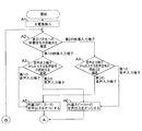
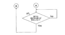
- 4 and 5 are flowcharts showing the processing procedure of the audio reproduction method of the present invention.
- the video display device 1 the first video / audio generator 2 1 via the first video input terminal 13 and a first audio input terminal 15 is connected
- the image display system second video / audio generator 2 S is connected via a second video input terminal 14 and a second audio input terminal 16 as an example, the audio reproducing method of the present invention
- Configuration of the video display system is not intended to be limited to the configuration shown in FIG. 2, for example, the first video / audio generator 2 first or second video / audio generator 2 2 of either the speech signal It may be replaced with a sound reproducing device that outputs only the sound.
- step A1 when the video display device 1 is activated by the user turning on the main power supply (step A1), the processing device 19 is set by the user using the operation switch, the remote controller, or the menu image.
- step A2 The supply source of the video signal supplied to the display panel 11 is confirmed (step A2).
- step A2 it is confirmed which of the first video input terminal 13 and the second video input terminal 14 is set to supply the video signal input from which video input terminal to the display panel 11.
- the processing device 19 proceeds to the processing of step A 3 and uses the operation switch, the remote controller, or the menu image.
- the supply source of the audio signal output from the audio output terminal 17 set by the user is confirmed.
- the processing device 19 When the audio signal output from the audio output terminal 17 is an audio signal input from the first audio input terminal 15 corresponding to the video signal input from the first video input terminal 13, the processing device 19 It is determined that the audio signal output from the audio output terminal 17 and the audio signal supplied to the built-in speaker 12 are the same. Then, by controlling the video / audio control circuit 18, the audio signal input from the first audio input terminal 15 is supplied to the audio output terminal 17, and the audio output of the built-in speaker 12 is turned off (muted) (Ste A5). At this time, the processing device 19 may use a background art process that turns off the sound output of the built-in speaker 12 by detecting the connection of the sound output device 3 to the sound output terminal 17.
- step A3 the audio signal output from the audio output terminal 17 is an audio signal input from the second audio input terminal 16 corresponding to the video signal input from the second video input terminal 14.
- the processing device 19 determines that the audio signal output from the audio output terminal 17 is different from the audio signal supplied to the built-in speaker 12. Then, by controlling the video / audio control circuit 18, the audio signal input from the second audio input terminal 16 is supplied to the audio output terminal 17, and the audio output of the built-in speaker 12 is turned on (step A6). .
- step A5 or step A6 the processing device 19 checks whether or not the user has switched the setting of the video input terminal or the audio input terminal (step A7 in FIG. 5). When the setting switching of the video input terminal or the audio input terminal occurs, the processing device 19 repeats the processing from step A2. If the setting switching of the video input terminal or the audio input terminal has not occurred, the process of step A7 is repeated.
- the processing device 19 proceeds to the processing in step A4, and the operation switch, remote The source of the audio signal output from the audio output terminal set by the user using the controller or menu image is confirmed.
- the processing device 19 determines that the audio signal output from the output terminal 17 is different from the audio signal supplied to the built-in speaker 12. Then, by controlling the video / audio control circuit 18, the audio signal input from the first audio input terminal 15 is supplied to the audio output terminal 17, and the audio output of the built-in speaker 12 is turned on (step A6). .
- step A4 the audio signal output from the audio output terminal 17 is an audio signal input from the second audio input terminal 16 corresponding to the video signal input from the second video input terminal 14.
- the processing device 19 determines that the audio signal output from the audio output terminal 17 and the audio signal supplied to the built-in speaker 12 are the same. Then, by controlling the video / audio control circuit 18, the audio signal input from the second audio input terminal 16 is supplied to the audio output terminal 17, and the audio output of the built-in speaker 12 is turned off (muted) (Ste A5).
- the processing device 19 may use background art processing for turning off the sound output of the built-in speaker 12 by detecting the connection of the sound output device 3 to the sound output terminal 17.
- step A5 or step A6 the processing device 19 checks whether or not the user has switched the setting of the video input terminal or the audio input terminal (step A7 in FIG. 5). When the setting switching of the video input terminal or the audio input terminal occurs, the processing device 19 repeats the processing from step A2. If the setting switching of the video input terminal or the audio input terminal has not occurred, the process of step A7 is repeated.
- the video display device 1 includes two video input terminals and two audio input terminals corresponding to the video display terminal 1 is shown, but even in a configuration including three or more video input terminals and audio input terminals,
- the video signals supplied to the display panel 11 and the corresponding audio signals are classified into other video signals and their audio signals, and the audio signals output from the audio output terminal 17 correspond to the video signals supplied to the display panel 11. If it is determined whether or not, the same processing as described above can be executed.
- the audio signal output from the audio output terminal 17 and the audio signal supplied to the built-in speaker 12 are the same depending on whether or not the audio signal corresponds to the video signal supplied to the display panel 11.
- the present invention can determine whether or not the audio signal output from the audio output terminal 17 shown in FIG. 2 and the audio signal supplied to the built-in speaker 12 are the same. Any determination method may be used.
- the waveform of the audio signal output from the audio output terminal 17 and the waveform of the audio signal supplied to the built-in speaker 12 may be compared to determine whether or not they match. Further, by monitoring the output destination of each audio signal input to the video / audio control circuit 18, it may be determined whether or not the audio signal supplied to the audio output terminal 17 and the built-in speaker 12 is the same. .
- the same audio signal as that supplied to the built-in speaker 12 is output from the audio output terminal 17.
- the sound output of the built-in speaker 12 is turned off and a sound signal different from the sound signal supplied to the built-in speaker 12 is output from the sound output terminal 17, the sound output of the built-in speaker 12 is turned on.
- Different audio signals can be supplied to the terminal 17 depending on the use of the user.
- the user sets only the supply source (video input terminal) of the video signal to be displayed on the display panel 11 and the supply source (audio input terminal) of the audio signal output from the audio output terminal 17 for the video display device 1. Therefore, the setting operation by the user is reduced.
Landscapes
- Engineering & Computer Science (AREA)
- Multimedia (AREA)
- Signal Processing (AREA)
- Databases & Information Systems (AREA)
- Television Receiver Circuits (AREA)
- Details Of Audible-Bandwidth Transducers (AREA)
Abstract
L'invention concerne un dispositif d'affichage vidéo comprenant un terminal de sortie audio, un haut-parleur intégré et une pluralité de terminaux d'entrée audio. La sortie audio du haut-parleur intégré est fermée lorsqu'un signal audio identique au signal audio fourni au haut-parleur intégré est sorti d'un terminal de sortie audio. La sortie audio du haut-parleur intégré est ouverte lorsqu'un signal audio différent du signal audio fourni au haut-parleur intégré est sorti du terminal de sortie audio.
Priority Applications (2)
| Application Number | Priority Date | Filing Date | Title |
|---|---|---|---|
| PCT/JP2009/061094 WO2010146686A1 (fr) | 2009-06-18 | 2009-06-18 | Dispositif d'affichage vidéo et procédé de reproduction audio associé |
| JP2011519364A JP5115775B2 (ja) | 2009-06-18 | 2009-06-18 | 映像表示装置及びその音声再生方法 |
Applications Claiming Priority (1)
| Application Number | Priority Date | Filing Date | Title |
|---|---|---|---|
| PCT/JP2009/061094 WO2010146686A1 (fr) | 2009-06-18 | 2009-06-18 | Dispositif d'affichage vidéo et procédé de reproduction audio associé |
Publications (1)
| Publication Number | Publication Date |
|---|---|
| WO2010146686A1 true WO2010146686A1 (fr) | 2010-12-23 |
Family
ID=43356024
Family Applications (1)
| Application Number | Title | Priority Date | Filing Date |
|---|---|---|---|
| PCT/JP2009/061094 Ceased WO2010146686A1 (fr) | 2009-06-18 | 2009-06-18 | Dispositif d'affichage vidéo et procédé de reproduction audio associé |
Country Status (2)
| Country | Link |
|---|---|
| JP (1) | JP5115775B2 (fr) |
| WO (1) | WO2010146686A1 (fr) |
Citations (5)
| Publication number | Priority date | Publication date | Assignee | Title |
|---|---|---|---|---|
| JP2003125299A (ja) * | 2001-10-12 | 2003-04-25 | Funai Electric Co Ltd | テレビジョン受信装置 |
| JP2005333551A (ja) * | 2004-05-21 | 2005-12-02 | Canon Inc | Tv受信機 |
| WO2007052625A1 (fr) * | 2005-10-31 | 2007-05-10 | Matsushita Electric Industrial Co., Ltd. | Système audiovisuel |
| JP2007522716A (ja) * | 2004-01-23 | 2007-08-09 | トムソン ライセンシング | 選択可能な音声出力構成 |
| JP2007295383A (ja) * | 2006-04-26 | 2007-11-08 | Funai Electric Co Ltd | 音声出力装置 |
-
2009
- 2009-06-18 WO PCT/JP2009/061094 patent/WO2010146686A1/fr not_active Ceased
- 2009-06-18 JP JP2011519364A patent/JP5115775B2/ja not_active Expired - Fee Related
Patent Citations (5)
| Publication number | Priority date | Publication date | Assignee | Title |
|---|---|---|---|---|
| JP2003125299A (ja) * | 2001-10-12 | 2003-04-25 | Funai Electric Co Ltd | テレビジョン受信装置 |
| JP2007522716A (ja) * | 2004-01-23 | 2007-08-09 | トムソン ライセンシング | 選択可能な音声出力構成 |
| JP2005333551A (ja) * | 2004-05-21 | 2005-12-02 | Canon Inc | Tv受信機 |
| WO2007052625A1 (fr) * | 2005-10-31 | 2007-05-10 | Matsushita Electric Industrial Co., Ltd. | Système audiovisuel |
| JP2007295383A (ja) * | 2006-04-26 | 2007-11-08 | Funai Electric Co Ltd | 音声出力装置 |
Also Published As
| Publication number | Publication date |
|---|---|
| JPWO2010146686A1 (ja) | 2012-11-29 |
| JP5115775B2 (ja) | 2013-01-09 |
Similar Documents
| Publication | Publication Date | Title |
|---|---|---|
| JP5527963B2 (ja) | 音声出力装置 | |
| WO2007040053A1 (fr) | Dispositif de sortie sonore vidéo et contrôleur de haut-parleur externe | |
| WO2007052637A1 (fr) | Appareil de reproduction sonore et systeme audiovisuel | |
| JP5428779B2 (ja) | 放送受信装置 | |
| CN101458942A (zh) | 音视频装置及控制方法 | |
| CN102598703B (zh) | 用于控制用于内容项的回放的装置的设置的方法和设备 | |
| JP5115775B2 (ja) | 映像表示装置及びその音声再生方法 | |
| JP5262526B2 (ja) | 映像音声再生システム、av増幅装置およびプログラム | |
| JP2005175570A (ja) | 映像音声出力装置 | |
| JP4635549B2 (ja) | 情報処理装置および方法 | |
| JP2009130706A (ja) | 音声出力制御システム | |
| JP5375509B2 (ja) | コンテンツ送受信装置およびそのプログラム | |
| JP5625456B2 (ja) | コンテンツ送受信システム、コンテンツ送信装置およびコンテンツ受信装置 | |
| JP2010098549A (ja) | 入力割当装置及びそのプログラム | |
| JP2008271353A (ja) | 音響再生装置 | |
| JP5085664B2 (ja) | 映像・音声処理装置および映像・音声処理方法 | |
| JP5347308B2 (ja) | コンテンツ受信装置及びコンテンツ再生装置 | |
| WO2009144788A1 (fr) | Unité d'affichage vidéo avec fonction de sortie audio intégrée et procédé d'exécution d'une commande de volume sur celle-ci | |
| JP2015144485A (ja) | コンテンツ再生装置、およびコンテンツ再生装置の動作方法 | |
| JP5387312B2 (ja) | コンテンツ送受信システム、及び、通信システム | |
| JP2012147113A (ja) | コンテンツ再生装置、およびコンテンツ再生装置の動作方法 | |
| CN100508051C (zh) | 便携式光盘读取装置的音频信号输入输出控制装置及方法 | |
| JP2007110430A (ja) | 音声処理装置およびそれを備えた表示装置 | |
| JP2009081757A (ja) | 電子機器 | |
| JP5516656B2 (ja) | コンテンツ受信装置及びコンテンツ再生装置 |
Legal Events
| Date | Code | Title | Description |
|---|---|---|---|
| 121 | Ep: the epo has been informed by wipo that ep was designated in this application |
Ref document number: 09846179 Country of ref document: EP Kind code of ref document: A1 |
|
| WWE | Wipo information: entry into national phase |
Ref document number: 2011519364 Country of ref document: JP |
|
| NENP | Non-entry into the national phase |
Ref country code: DE |
|
| 122 | Ep: pct application non-entry in european phase |
Ref document number: 09846179 Country of ref document: EP Kind code of ref document: A1 |