WO2010146826A1 - Filtre d'onde acoustique de surface de type en échelle, et duplexeur utilisant ce filtre - Google Patents
Filtre d'onde acoustique de surface de type en échelle, et duplexeur utilisant ce filtre Download PDFInfo
- Publication number
- WO2010146826A1 WO2010146826A1 PCT/JP2010/003948 JP2010003948W WO2010146826A1 WO 2010146826 A1 WO2010146826 A1 WO 2010146826A1 JP 2010003948 W JP2010003948 W JP 2010003948W WO 2010146826 A1 WO2010146826 A1 WO 2010146826A1
- Authority
- WO
- WIPO (PCT)
- Prior art keywords
- acoustic wave
- wave resonator
- series
- parallel
- piezoelectric substrate
- Prior art date
- Legal status (The legal status is an assumption and is not a legal conclusion. Google has not performed a legal analysis and makes no representation as to the accuracy of the status listed.)
- Ceased
Links
Images








Classifications
-
- H—ELECTRICITY
- H03—ELECTRONIC CIRCUITRY
- H03H—IMPEDANCE NETWORKS, e.g. RESONANT CIRCUITS; RESONATORS
- H03H9/00—Networks comprising electromechanical or electro-acoustic elements; Electromechanical resonators
- H03H9/46—Filters
- H03H9/64—Filters using surface acoustic waves
- H03H9/6423—Means for obtaining a particular transfer characteristic
- H03H9/6433—Coupled resonator filters
- H03H9/6483—Ladder SAW filters
-
- H—ELECTRICITY
- H03—ELECTRONIC CIRCUITRY
- H03H—IMPEDANCE NETWORKS, e.g. RESONANT CIRCUITS; RESONATORS
- H03H9/00—Networks comprising electromechanical or electro-acoustic elements; Electromechanical resonators
- H03H9/02—Details
- H03H9/02535—Details of surface acoustic wave devices
- H03H9/02818—Means for compensation or elimination of undesirable effects
- H03H9/02834—Means for compensation or elimination of undesirable effects of temperature influence
-
- H—ELECTRICITY
- H03—ELECTRONIC CIRCUITRY
- H03H—IMPEDANCE NETWORKS, e.g. RESONANT CIRCUITS; RESONATORS
- H03H9/00—Networks comprising electromechanical or electro-acoustic elements; Electromechanical resonators
- H03H9/70—Multiple-port networks for connecting several sources or loads, working on different frequencies or frequency bands, to a common load or source
- H03H9/72—Networks using surface acoustic waves
- H03H9/725—Duplexers
-
- H—ELECTRICITY
- H03—ELECTRONIC CIRCUITRY
- H03H—IMPEDANCE NETWORKS, e.g. RESONANT CIRCUITS; RESONATORS
- H03H9/00—Networks comprising electromechanical or electro-acoustic elements; Electromechanical resonators
- H03H9/02—Details
- H03H9/02535—Details of surface acoustic wave devices
- H03H9/02818—Means for compensation or elimination of undesirable effects
- H03H9/02944—Means for compensation or elimination of undesirable effects of ohmic loss
Definitions
- the present invention relates to a ladder-type elastic wave filter and a duplexer using the same.
- the conventional ladder type acoustic wave filter 100 includes a piezoelectric substrate 101, a series acoustic wave resonator 102 a formed on the piezoelectric substrate 101, and a series acoustic wave resonator 102 a on the piezoelectric substrate 101.
- the film thickness Ha of the dielectric film 103a is formed such that the frequency temperature coefficient of the series acoustic wave resonator 102a is zero.
- the film thickness Hb of the dielectric film 103b is thinner than the film thickness Ha, and is formed so that the frequency temperature coefficient of the parallel acoustic wave resonator 102b becomes zero.
- Patent Document 1 is known as prior art document information related to the invention of this application.
- the conventional ladder-type acoustic wave filter has a problem that resistance loss increases at high temperatures and the pass characteristics deteriorate.
- an object of the present invention is to improve the passage characteristics at high temperatures.
- the ladder-type acoustic wave filter of the present invention is formed on a piezoelectric substrate, a first series acoustic wave resonator formed on the piezoelectric substrate and connected in series between the input terminal and the output terminal, and the piezoelectric substrate.
- a parallel acoustic wave resonator connected in parallel between the series acoustic wave resonator and the ground terminal, and a dielectric film formed on the piezoelectric substrate so as to cover the first series acoustic wave resonator. .
- the piezoelectric substrate is formed using a material having a negative temperature coefficient
- the dielectric film is formed using a material having a positive temperature coefficient
- the film thickness of the dielectric film is the first series elasticity.
- the wave resonator is formed thicker than the film thickness at which the frequency temperature coefficient is zero.
- the pass band of the series acoustic wave resonator moves to the high frequency side as the temperature rises.
- the ladder-type acoustic wave filter of the present invention is formed on a piezoelectric substrate, a series acoustic wave resonator formed on the piezoelectric substrate and connected in series between the input terminal and the output terminal, and the piezoelectric substrate.
- a first parallel acoustic wave resonator connected in parallel between the series acoustic wave resonator and the ground terminal, and a dielectric formed on the piezoelectric substrate so as to cover the first parallel acoustic wave resonator With a membrane.
- the piezoelectric substrate is formed using a material having a negative temperature coefficient
- the dielectric film is formed using a material having a positive temperature coefficient
- the film thickness of the dielectric film is the first parallel elasticity.
- the wave resonator is formed thinner than the film thickness at which the frequency temperature coefficient is zero.
- the passband of the parallel acoustic wave resonator moves to the low frequency side as the temperature rises.
- FIG. 1 is a block diagram of a duplexer according to the first embodiment.
- FIG. 2 is a diagram for explaining pass characteristics of the duplexer in the first embodiment.
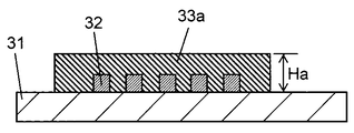
- FIG. 3A is a diagram illustrating a dielectric film that covers the acoustic wave resonator.
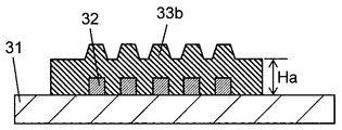
- FIG. 3B is a diagram illustrating a dielectric film that covers the acoustic wave resonator.
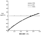
- FIG. 4 is a diagram showing the relationship between the film thickness of the dielectric film covering the acoustic wave resonator and the frequency temperature characteristic.
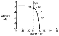
- FIG. 5A is a diagram for explaining the transmission characteristics of the transmission filter in the first embodiment.
- FIG. 5B is a diagram for explaining the transmission characteristics of the transmission filter in the first embodiment.
- FIG. 5A is a diagram for explaining the transmission characteristics of the transmission filter in the first embodiment.
- FIG. 5C is a diagram illustrating the transmission characteristics of the transmission filter in the first embodiment.
- FIG. 6 is a diagram for explaining the transmission characteristics of the transmission filter in the first embodiment.
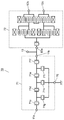
- FIG. 7 is a block diagram of the duplexer according to the second embodiment.
- FIG. 8A is a diagram for explaining the transmission characteristics of the transmission filter in the second embodiment.
- FIG. 8B is a diagram for explaining the transmission characteristics of the transmission filter in the second embodiment.
- FIG. 8C is a diagram for explaining the transmission characteristics of the transmission filter in the second embodiment.
- FIG. 9 is a block diagram of a duplexer in the third embodiment.
- FIG. 10 is a diagram for explaining a dielectric film covering a conventional acoustic wave resonator.
- FIG. 1 is a block diagram of a duplexer 10 for Band 2 of the W-CDMA standard in the first embodiment.
- the duplexer 10 includes a transmission filter 11 that passes signals in the Band2 transmission band (1.85 GHz to 1.91 GHz), a reception filter 12 that passes signals in the Band2 reception band (1.93 GHz to 1.99 GHz), and An antenna terminal 13 connected to the output terminal 11 b of the transmission filter 11 and the input terminal 12 a of the reception filter 12 is provided.
- the transmission filter 11 includes four series acoustic wave resonators 11c, 11d, 11e, and 11f that are formed on a piezoelectric substrate (not shown) and connected in series between the input terminal 11a and the output terminal 11b. ing.
- the series acoustic wave resonator 11e having the largest capacity is referred to as a first series acoustic wave resonator, and the others are referred to as second series acoustic wave resonators.
- the transmission filter 11 includes three parallel elastic wave resonators 11g, 11h, and 11i connected in parallel between the series elastic wave resonators 11c to 11f and the ground terminal 11j.
- FIG. 2 is a graph of the frequency (GHz) on the horizontal axis and the pass characteristic (dB) on the vertical axis, and shows the transmission characteristic 21 of the transmission filter 11 and the reception characteristic 22 of the reception filter 12.
- the transmission filter 11 needs to pass the signal in the transmission band with low loss and sufficiently suppress the signal in the reception band. Further, the reception filter 12 needs to pass the signal in the reception band with a low loss and sufficiently suppress the signal in the transmission band.
- the Band 2 transmission band (1.85 GHz to 1.91 GHz) and the reception band (1.93 GHz to 1.99 GHz) of the W-CDMA standard are described.
- the problem is that the interval (cross band) of the frequency band is as narrow as 20 MHz. Therefore, it is necessary to ensure attenuation in the reception band by making the right shoulder R2 of the transmission characteristic 21 sufficiently steep.
- the steepness of R2 (the difference between the frequency at which the pass characteristic is ⁇ 3 dB and the frequency at which the pass characteristic first becomes the attenuation pole) is 15 MHz, which is compared with the steepness 22 MHz of the left shoulder R1 of the transmission band. The steepness is large.
- the characteristic of the right shoulder R2 of the transmission characteristic 21 is important.
- the pass characteristic on the low frequency side (1.85 GHz) of the transmission band is 1.9 dB
- the pass characteristic on the high frequency side (1.91 GHz) of the transmission band is 2.4 dB. Yes. This is because the steepness of the right shoulder R2 of the transmission band is made larger than the steepness of the left shoulder R1.
- the pass characteristic of the right shoulder R2 of the transmission characteristic 21 is a bottleneck of the pass characteristic of the entire transmission band.
- the transmission characteristic 21 of the transmission filter 11 depends on the temperature.
- the transmission filter 11 includes series acoustic wave resonators 11c, 11d, 11e, and 11f and parallel acoustic wave resonators 11g, 11h, and 11i, and a metal such as aluminum or copper is respectively formed on the piezoelectric substrate. It has a comb electrode as a main component. For this reason, as the temperature rises, the resistivity of the comb electrode increases and the loss of the transmission characteristic 21 increases. Therefore, in the design of the transmission filter 11, it is necessary that the loss on the high frequency side (1.91 GHz) of the transmission characteristics satisfies the design specification at the upper limit temperature of the temperature range in which the operation is guaranteed.
- the transmission filter 11 sets the frequency temperature characteristics of the series elastic wave resonators 11c, 11d, 11e, and 11f to be positive so that the right shoulder R2 of the transmission band is increased in frequency as the temperature rises. To increase the loss due to the resistance loss of the comb electrode.
- the right shoulder R2 moves to the low frequency side, but the resistance loss of the comb electrode decreases, so that the increase of the loss on the high frequency side (1.91 GHz) of the transmission band is suppressed.
- the film thickness of the dielectric film formed on the piezoelectric substrate included in the transmission filter 11 so as to cover the series elastic wave resonators 11c, 11d, 11e, and 11f is adjusted. A method is mentioned.
- FIGS. 3A and 3B are diagrams illustrating a dielectric film covering the acoustic wave resonator.
- a series acoustic wave resonator 32 is formed on a piezoelectric substrate 31 using lithium tantalate or lithium niobate.
- a dielectric film 33 a is formed on the piezoelectric substrate 31 so as to cover the series elastic wave resonator 32.
- the film thickness of the dielectric film 33a is Ha.
- the dielectric film 33a may be a dielectric film 33b having a convex shape on the upper surface. By providing a convex shape such as the dielectric film 33b, an effect of suppressing unnecessary spurious such as Rayleigh mode spurious can be obtained.
- the piezoelectric substrate 31 using lithium tantalate, lithium niobate, or the like generally has a negative temperature characteristic in frequency temperature characteristics. Therefore, by forming a dielectric film having a positive temperature characteristic such as silicon dioxide with a predetermined film thickness, the frequency temperature characteristic of the elastic wave excited by the series elastic wave resonator 32 can be adjusted.
- FIG. 4 shows a standardized film thickness (H / ⁇ ) obtained by dividing the film thickness H of silicon dioxide, which is a dielectric film, by a wavelength ⁇ when a lithium niobate is used as the piezoelectric substrate 31, and a series acoustic wave resonator.
- 32 shows the frequency-temperature characteristic (TCF) (ppm / ° C.) of the elastic wave excited by 32.
- TCF frequency-temperature characteristic
- the case (5YX) is indicated by a broken line, and the case where the cut angle of the rotating Y plate of the piezoelectric substrate is 15 ° (15YX) is indicated by a dotted line.
- the normalized film thickness (H / ⁇ ) of silicon dioxide is about 0.4, the frequency temperature characteristic becomes almost zero.
- the film thickness of the dielectric film such as silicon dioxide is adjusted in accordance with the temperature characteristic of the piezoelectric substrate 31 so that the frequency temperature characteristic becomes almost zero.
- the film thickness of the dielectric film such as silicon dioxide covering the series elastic wave resonator is made thicker than the film thickness at which the frequency temperature characteristic becomes zero. Therefore, the frequency temperature characteristic is positive.
- the film thickness of the dielectric film covering the series elastic wave resonators 11c to 11f is formed to be thicker than the film thickness at which the frequency temperature characteristics of the series elastic wave resonators 11c to 11f are zero.
- FIG. 5A shows a transmission characteristic 51 of the conventional transmission filter at normal temperature (25 ° C.) and a transmission characteristic 52 of the conventional transmission filter at high temperature (85 ° C.).
- the conventional transmission characteristic 52 at a high temperature has a greater loss than the conventional transmission characteristic 51 at a normal temperature because the resistance loss of the comb electrode increases.
- the pass characteristic on the high frequency side of the transmission band is 2.4 dB (point 51a) at room temperature and deteriorates to 2.8 dB (point 52a) at high temperature.
- FIG. 5B shows a transmission characteristic 53 at normal temperature (25 ° C.) and a transmission characteristic 54 at high temperature (85 ° C.) of the transmission filter 11 according to the first embodiment.
- the transmission characteristic 54 at high temperature has a greater loss than the transmission characteristic 53 at normal temperature because the resistance loss of the comb-tooth electrode increases.
- the series elastic wave resonators 11c, 11d, 11e, and 11f that determine the characteristics on the high frequency side of the transmission characteristic, that is, the first series elastic wave resonator and the second series elastic wave resonator have positive frequency temperature characteristics. is there.
- the thickness of the dielectric film covering the first series acoustic wave resonator and the second series acoustic wave resonator is formed to be greater than the thickness at which the frequency-temperature characteristic is 0.
- the frequency temperature characteristic of the resonator is positive.
- the transmission characteristic 54 at a high temperature is shifted to a higher frequency side than the transmission characteristic 53 at a normal temperature.
- the pass characteristic on the high frequency side of the transmission band is 2.4 dB (point 53a) at room temperature, and 2.6 dB (point 54a) at high temperature.
- the transmission filter 11 according to the first embodiment has improved pass characteristics at high temperatures as compared with the conventional transmission filter.
- series elastic wave resonators 11c to 11f are connected in series, but the number of series elastic wave resonators is not particularly limited. For example, the same effect can be obtained even if the first series acoustic wave resonator is used alone. Further, the number of the first and second series acoustic wave resonators is not particularly limited to the above example.
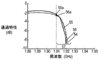
- FIG. 5C shows a dielectric film covering the series elastic wave resonator 11e (first series elastic wave resonator) having the largest capacitance among the series elastic wave resonators 11c, 11d, 11e, and 11f included in the transmission filter 11. Only the film thickness shows a transmission characteristic 55 at room temperature (25 ° C.) and a transmission characteristic 56 at high temperature (85 ° C.) when the film is formed thicker than the film thickness at which the frequency temperature characteristic becomes zero.
- the capacitance of the resonator is proportional to the product of the intersection width of the electrode fingers and the number of pairs of electrode fingers in the comb-tooth electrode.
- the transmission characteristic 56 at a high temperature is equivalent to the transmission characteristic 54 in FIG. 5B (shown by a dotted line in FIG. 5C), but the transmission characteristic 56a on the high frequency side of the transmission band is the same, but the stop band 57 The amount of attenuation increases.
- a transmission characteristic 60 in FIG. 6 indicates the transmission characteristic of the transmission filter 11.
- the transmission characteristics 61c, 61d, 61e, and 61f indicate the transmission characteristics of the series acoustic wave resonators 11c, 11d, 11e, and 11f included in the transmission filter 11, respectively.
- the film thickness of the dielectric film covering the series elastic wave resonator 11 e (first series elastic wave resonator) having the largest capacity is larger than the film thickness at which the frequency temperature characteristic becomes zero. It is made thicker.
- the anti-resonance frequency 62e of the series elastic wave resonator 11e moves to the high frequency side, and the other series elastic wave resonators 11c, 11d, 11f (first).
- the anti-resonance frequencies 62c, 62d and 62f of the second series elastic wave resonator) do not move.
- the slope of the attenuation characteristic on the high frequency side of the transmission filter 11 greatly depends on the series acoustic wave resonator 11e having the largest capacitance. Therefore, the entire transmission characteristic 60 composed of these transmission characteristics 61c, 61d, 61e, and 61f moves to the high frequency side only as the temperature rises, and the attenuation amount of the stop band is maintained.
- the series acoustic wave resonator 11e has the largest capacity among the series acoustic wave resonators 11c, 11d, 11e, and 11f included in the transmission filter 11.
- the present invention is not limited to this, and the other series elastic wave resonators have the largest capacitance, and only the film thickness of the dielectric film covering the series elastic wave resonators is larger than the film thickness at which the frequency temperature characteristic becomes zero. Further, it may be formed thicker. Further, a plurality of series elastic wave resonators (first series elastic wave resonators) having the largest capacity may be provided.
- the capacity of the acoustic wave resonator can be adjusted by, for example, the electrode finger crossing width of the comb electrode, the number of electrode fingers, or the like.
- the duplexer using the transmission filter 11 according to the first embodiment, it is possible to secure a cross-band attenuation characteristic and a duplexer that suppresses deterioration of the transmission characteristic at a high temperature.
- the transmission filter 11 may be a surface acoustic wave propagating on the surface of the piezoelectric substrate 31 or a boundary elastic wave propagating on a boundary surface of a medium having a different wave propagation speed.
- FIG. 7 shows a duplexer 70 for Band 2. Like the duplexer 10 in FIG. 1, a ladder type transmission filter 71 and a DMS type reception filter 72 are connected to the antenna terminal 13. Yes.
- the frequency temperature characteristic of the parallel acoustic wave resonators 71g, 71h, 71i of the transmission filter 71 is deliberately made negative.
- the parallel acoustic wave resonator 71i having the smallest capacity is referred to as a first parallel acoustic wave resonator, and the others are referred to as second parallel acoustic wave resonators.
- the frequency temperature characteristics of the parallel acoustic wave resonators 71g, 71h, 71i can be made negative, and the transmission characteristics of the left shoulder of the transmission characteristics at high temperatures can be improved.
- FIG. 8A shows a conventional transmission characteristic 81 at normal temperature (25 ° C.) and a conventional transmission characteristic 82 at high temperature (85 ° C.).
- the conventional transmission characteristic 82 at a high temperature has an increased loss compared to the conventional transmission characteristic 81 at a normal temperature because the resistance loss increases.
- the pass characteristic on the low frequency side of the transmission band is 1.9 dB (point 81a) at room temperature and deteriorates to 2.3 dB (point 82a) at high temperature.
- FIG. 8B shows a transmission characteristic 83 of the transmission filter 71 according to the second embodiment at normal temperature (25 ° C.) and a transmission characteristic 84 at high temperature (85 ° C.). Similar to FIG. 8A, the transmission characteristic 84 at high temperature has a greater loss than the transmission characteristic 83 at normal temperature because the resistance loss increases. However, the parallel elastic wave resonators 71g, 71h, 71i that determine the low frequency side transmission characteristics have a negative frequency temperature characteristic. That is, since the film thicknesses of the dielectric films covering the first parallel elastic wave resonator and the second parallel elastic wave resonator are each made thinner than the film thickness at which the frequency temperature characteristic becomes 0, the parallel elastic wave The frequency temperature characteristic of the resonator is negative.
- the transmission filter 71 according to the second embodiment has improved pass characteristics on the low frequency side at a high temperature as compared with the conventional transmission filter.
- three parallel acoustic wave resonators 71g to 71i are connected in parallel, but the number of parallel acoustic wave resonators is not particularly limited. For example, the same effect can be obtained even if only the first parallel acoustic wave resonator is used.
- the number of first and second parallel acoustic wave resonators is not particularly limited to the above example.
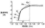
- FIG. 8C shows the film thickness of the dielectric film covering the parallel acoustic wave resonator 71i (first parallel acoustic wave resonator) having the smallest capacitance among the parallel acoustic wave resonators 71g, 71h, 71i included in the transmission filter 71.
- FIG. Only shows a transmission characteristic 85 at normal temperature (25 ° C.) and a transmission characteristic 86 at high temperature (85 ° C.) when the film is formed thinner than the film thickness at which the frequency temperature characteristic becomes zero.
- the transmission characteristic 86 at high temperature is equivalent to the transmission characteristic 84 on the low frequency side of the transmission band compared to the transmission characteristic 84 of FIG. 8B (shown by a dotted line in FIG. 8C), but the stop band.
- the amount of attenuation 87 has increased.
- the resonance frequency of the parallel elastic wave resonator 71i that has the greatest influence on the left shoulder of the transmission characteristics moves to the low frequency side, and the resonance frequencies of the other parallel elastic wave resonators 71g and 71h. This is because does not move.
- the parallel acoustic wave resonator 71i closest to the antenna terminal 13 has the smallest capacity. It was described as a resonator. However, the present invention is not limited to this, and the capacity of the resonant frequency of the other parallel acoustic wave resonators is the smallest, and the film thickness of the dielectric film covering the parallel acoustic wave resonators is a film whose frequency temperature characteristic is zero. You may form thinner than thickness.
- the capacity of the acoustic wave resonator can be adjusted by, for example, the electrode finger crossing width of the comb electrode, the number of electrode fingers, or the like.
- the duplexer using the transmission filter 71 according to the second embodiment, it is possible to secure the attenuation characteristic on the lower frequency side than the transmission band and to suppress the deterioration of the transmission characteristic at a high temperature. Can do.
- the thickness of the dielectric covering the series elastic wave resonators 71c, 71d, 71e, 71f of the transmission filter 71 is made thicker than the thickness at which the frequency-temperature characteristic is zero. May be.
- the transmission filter 71 according to the second embodiment may be a surface acoustic wave propagating on the surface of the piezoelectric substrate or a boundary acoustic wave propagating on the boundary surface of a medium having a different wave propagation speed.
- the duplexer 90 shown in FIG. 9 has a configuration in which a ladder-type transmission filter 91 and a ladder-type reception filter 92 are connected to the antenna terminal 13.
- the frequency temperature characteristic of the parallel acoustic wave resonators 91g, 91h, and 91i can be made negative, and the left shoulder passage characteristics of the reception characteristics at high temperatures can be improved.
- the thickness of the dielectric film covering the parallel acoustic wave resonator having the smallest capacitance may be formed thinner than the thickness at which the frequency temperature characteristic becomes zero. Good. Accordingly, it is possible to improve the left shoulder passage characteristic of the reception characteristic at a high temperature while maintaining the cross band attenuation characteristic.
- the frequency temperature is deliberately set.
- the characteristic may be positive.
- the frequency temperature characteristics of the series elastic wave resonators 92c, 92d, 92e, and 92f can be made positive, and the right shoulder passage characteristics of the reception characteristics at high temperatures can be improved.
- reception filter 92 may be a surface acoustic wave propagating on the surface of the piezoelectric substrate, or a boundary acoustic wave propagating on a boundary surface of a medium having a different wave propagation speed.
- the elastic wave filter according to the present invention and the duplexer using the elastic wave filter can improve the pass characteristic at a high temperature while ensuring the attenuation characteristic on the lower side than the pass band, and can be used for various electronic devices.
Landscapes
- Physics & Mathematics (AREA)
- Acoustics & Sound (AREA)
- Surface Acoustic Wave Elements And Circuit Networks Thereof (AREA)
- Piezo-Electric Or Mechanical Vibrators, Or Delay Or Filter Circuits (AREA)
Abstract
Priority Applications (3)
| Application Number | Priority Date | Filing Date | Title |
|---|---|---|---|
| US13/378,129 US9041486B2 (en) | 2009-06-18 | 2010-06-15 | Ladder type surface acoustic wave filter and duplexer using same |
| JP2011519547A JPWO2010146826A1 (ja) | 2009-06-18 | 2010-06-15 | ラダー型弾性波フィルタ及びこれを用いたデュプレクサ |
| CN201080026908.XA CN102460967B (zh) | 2009-06-18 | 2010-06-15 | 阶梯型弹性波滤波器及使用其的双工器 |
Applications Claiming Priority (2)
| Application Number | Priority Date | Filing Date | Title |
|---|---|---|---|
| JP2009144897 | 2009-06-18 | ||
| JP2009-144897 | 2009-06-18 |
Publications (1)
| Publication Number | Publication Date |
|---|---|
| WO2010146826A1 true WO2010146826A1 (fr) | 2010-12-23 |
Family
ID=43356159
Family Applications (1)
| Application Number | Title | Priority Date | Filing Date |
|---|---|---|---|
| PCT/JP2010/003948 Ceased WO2010146826A1 (fr) | 2009-06-18 | 2010-06-15 | Filtre d'onde acoustique de surface de type en échelle, et duplexeur utilisant ce filtre |
Country Status (4)
| Country | Link |
|---|---|
| US (1) | US9041486B2 (fr) |
| JP (1) | JPWO2010146826A1 (fr) |
| CN (2) | CN102460967B (fr) |
| WO (1) | WO2010146826A1 (fr) |
Cited By (4)
| Publication number | Priority date | Publication date | Assignee | Title |
|---|---|---|---|---|
| WO2012176455A1 (fr) * | 2011-06-23 | 2012-12-27 | パナソニック株式会社 | Filtre de type itératif à onde élastique et duplexeur d'antenne utilisant celui-ci |
| WO2013080461A1 (fr) * | 2011-11-30 | 2013-06-06 | パナソニック株式会社 | Filtre d'onde élastique de type échelle et duplexeur d'antenne utilisant celui-ci |
| CN106664072A (zh) * | 2014-07-31 | 2017-05-10 | 天工滤波方案日本有限公司 | 声波滤波器和使用其的双工器 |
| CN113474996A (zh) * | 2019-02-26 | 2021-10-01 | 京瓷株式会社 | 滤波器和多滤波器 |
Families Citing this family (14)
| Publication number | Priority date | Publication date | Assignee | Title |
|---|---|---|---|---|
| CN102422534B (zh) * | 2009-05-14 | 2015-02-04 | 天工松下滤波方案日本有限公司 | 天线共用器 |
| JP5796604B2 (ja) * | 2013-06-13 | 2015-10-21 | 株式会社村田製作所 | 分波装置 |
| DE102015106191A1 (de) * | 2015-04-22 | 2016-10-27 | Epcos Ag | Elektroakustisches Bauelement mit verbesserter Akustik |
| CN105490660B (zh) * | 2015-12-15 | 2018-07-10 | 北京中科飞鸿科技有限公司 | 减小大宽带低损耗梯形声表滤波器带内波动的方法 |
| DE102018102891A1 (de) * | 2017-02-13 | 2018-08-16 | Murata Manufacturing Co., Ltd. | Multiplexierer, Übertragungsvorrichtung und Empfangsvorrichtung |
| JP6913619B2 (ja) * | 2017-12-12 | 2021-08-04 | 株式会社村田製作所 | マルチプレクサ、高周波フロントエンド回路及び通信装置 |
| US20230336154A1 (en) * | 2020-06-26 | 2023-10-19 | Kyocera Corporation | Elastic wave device and communication device |
| WO2022039210A1 (fr) * | 2020-08-19 | 2022-02-24 | 株式会社村田製作所 | Dispositif à ondes élastiques |
| CN112511131B (zh) * | 2021-02-05 | 2021-05-25 | 成都频岢微电子有限公司 | 一种具有高隔离度和高通频带低频侧高陡峭度的双工器 |
| US12640703B2 (en) | 2021-07-30 | 2026-05-26 | Skyworks Solutions, Inc. | Acoustic wave device with dielectric layer for reduced transverse leakage |
| US12506464B2 (en) | 2021-12-06 | 2025-12-23 | Skyworks Solutions, Inc. | Multi-band surface acoustic wave filters |
| CN114531129A (zh) * | 2022-02-22 | 2022-05-24 | 重庆邮电大学 | 一种双模声耦合表面波滤波器 |
| US12648470B2 (en) | 2022-03-30 | 2026-06-02 | Skyworks Solutions, Inc. | Package with integrated device die at least disposed within carrier |
| CN116032246B (zh) * | 2023-03-27 | 2023-10-31 | 成都频岢微电子有限公司 | 一种双工器 |
Citations (4)
| Publication number | Priority date | Publication date | Assignee | Title |
|---|---|---|---|---|
| JP2000196409A (ja) * | 1998-12-28 | 2000-07-14 | Kyocera Corp | 弾性表面波フィルタ |
| JP2002330054A (ja) * | 2001-04-26 | 2002-11-15 | Murata Mfg Co Ltd | 弾性表面波装置、通信装置 |
| WO2005076473A1 (fr) * | 2004-02-06 | 2005-08-18 | Matsushita Electric Industrial Co., Ltd. | Filtres a ondes acoustiques de surface et unite commune d’antenne l’utilisant |
| WO2005088835A1 (fr) * | 2004-03-12 | 2005-09-22 | Murata Manufacturing Co., Ltd. | Demultiplexeur et filtre a ondes acoustiques de surface |
Family Cites Families (10)
| Publication number | Priority date | Publication date | Assignee | Title |
|---|---|---|---|---|
| JP3293578B2 (ja) * | 1998-12-24 | 2002-06-17 | 日本電気株式会社 | 弾性表面波素子 |
| JP3435640B2 (ja) | 2000-05-22 | 2003-08-11 | 株式会社村田製作所 | 縦結合共振子型弾性表面波フィルタ |
| US6420820B1 (en) * | 2000-08-31 | 2002-07-16 | Agilent Technologies, Inc. | Acoustic wave resonator and method of operating the same to maintain resonance when subjected to temperature variations |
| JP3826816B2 (ja) * | 2001-08-29 | 2006-09-27 | 株式会社村田製作所 | 弾性表面波装置 |
| JP3945363B2 (ja) * | 2001-10-12 | 2007-07-18 | 株式会社村田製作所 | 弾性表面波装置 |
| JP3889351B2 (ja) * | 2002-12-11 | 2007-03-07 | Tdk株式会社 | デュプレクサ |
| CN101128977A (zh) * | 2005-02-28 | 2008-02-20 | 松下电器产业株式会社 | 压电滤波器以及使用该压电滤波器的双工器和通信装置 |
| JP4917396B2 (ja) | 2006-09-25 | 2012-04-18 | 太陽誘電株式会社 | フィルタおよび分波器 |
| JP4943137B2 (ja) * | 2006-12-25 | 2012-05-30 | 京セラ株式会社 | 分波器および通信装置 |
| CN104702239B (zh) * | 2011-06-23 | 2017-09-22 | 天工滤波方案日本有限公司 | 梯型弹性波滤波器及使用该弹性波滤波器的天线双工器 |
-
2010
- 2010-06-15 WO PCT/JP2010/003948 patent/WO2010146826A1/fr not_active Ceased
- 2010-06-15 CN CN201080026908.XA patent/CN102460967B/zh active Active
- 2010-06-15 CN CN201410789454.1A patent/CN104485918B/zh active Active
- 2010-06-15 US US13/378,129 patent/US9041486B2/en active Active
- 2010-06-15 JP JP2011519547A patent/JPWO2010146826A1/ja not_active Withdrawn
Patent Citations (4)
| Publication number | Priority date | Publication date | Assignee | Title |
|---|---|---|---|---|
| JP2000196409A (ja) * | 1998-12-28 | 2000-07-14 | Kyocera Corp | 弾性表面波フィルタ |
| JP2002330054A (ja) * | 2001-04-26 | 2002-11-15 | Murata Mfg Co Ltd | 弾性表面波装置、通信装置 |
| WO2005076473A1 (fr) * | 2004-02-06 | 2005-08-18 | Matsushita Electric Industrial Co., Ltd. | Filtres a ondes acoustiques de surface et unite commune d’antenne l’utilisant |
| WO2005088835A1 (fr) * | 2004-03-12 | 2005-09-22 | Murata Manufacturing Co., Ltd. | Demultiplexeur et filtre a ondes acoustiques de surface |
Cited By (16)
| Publication number | Priority date | Publication date | Assignee | Title |
|---|---|---|---|---|
| CN104702239B (zh) * | 2011-06-23 | 2017-09-22 | 天工滤波方案日本有限公司 | 梯型弹性波滤波器及使用该弹性波滤波器的天线双工器 |
| US9203376B2 (en) | 2011-06-23 | 2015-12-01 | Skyworks Panasonic Filter Solutions Japan Co., Ltd. | Ladder-type surface acoustic wave filter and duplexer including the same |
| JP5182459B2 (ja) * | 2011-06-23 | 2013-04-17 | パナソニック株式会社 | ラダー型弾性波フィルタ及びこれを用いたアンテナ共用器 |
| US9819329B2 (en) | 2011-06-23 | 2017-11-14 | Skyworks Filter Solutions Japan Co., Ltd. | Ladder-type surface acoustic wave filter including series and parallel resonators |
| CN103004085B (zh) * | 2011-06-23 | 2015-04-15 | 天工松下滤波方案日本有限公司 | 梯型弹性波滤波器及使用该弹性波滤波器的天线双工器 |
| WO2012176455A1 (fr) * | 2011-06-23 | 2012-12-27 | パナソニック株式会社 | Filtre de type itératif à onde élastique et duplexeur d'antenne utilisant celui-ci |
| CN103004085A (zh) * | 2011-06-23 | 2013-03-27 | 松下电器产业株式会社 | 梯型弹性波滤波器及使用该弹性波滤波器的天线双工器 |
| CN104702239A (zh) * | 2011-06-23 | 2015-06-10 | 天工松下滤波方案日本有限公司 | 梯型弹性波滤波器及使用该弹性波滤波器的天线双工器 |
| JP2017153132A (ja) * | 2011-11-30 | 2017-08-31 | スカイワークスフィルターソリューションズジャパン株式会社 | ラダー型弾性波フィルタと、これを用いたアンテナ共用器 |
| US9467117B2 (en) | 2011-11-30 | 2016-10-11 | Skyworks Filter Solutions Japan Co., Ltd. | Ladder-type elastic wave filter and antenna duplexer using same |
| JPWO2013080461A1 (ja) * | 2011-11-30 | 2015-04-27 | スカイワークス・パナソニック フィルターソリューションズ ジャパン株式会社 | ラダー型弾性波フィルタと、これを用いたアンテナ共用器 |
| WO2013080461A1 (fr) * | 2011-11-30 | 2013-06-06 | パナソニック株式会社 | Filtre d'onde élastique de type échelle et duplexeur d'antenne utilisant celui-ci |
| US10044340B2 (en) | 2011-11-30 | 2018-08-07 | Skyworks Filter Solutions Japan Co., Ltd. | Ladder-type elastic wave filter having series and parallel resonators |
| CN106664072A (zh) * | 2014-07-31 | 2017-05-10 | 天工滤波方案日本有限公司 | 声波滤波器和使用其的双工器 |
| JP2017526254A (ja) * | 2014-07-31 | 2017-09-07 | スカイワークスフィルターソリューションズジャパン株式会社 | 弾性波フィルタとこれを使用するデュプレクサ |
| CN113474996A (zh) * | 2019-02-26 | 2021-10-01 | 京瓷株式会社 | 滤波器和多滤波器 |
Also Published As
| Publication number | Publication date |
|---|---|
| US20120086521A1 (en) | 2012-04-12 |
| JPWO2010146826A1 (ja) | 2012-11-29 |
| CN104485918A (zh) | 2015-04-01 |
| US9041486B2 (en) | 2015-05-26 |
| CN104485918B (zh) | 2018-01-05 |
| CN102460967B (zh) | 2015-01-21 |
| HK1206154A1 (en) | 2015-12-31 |
| CN102460967A (zh) | 2012-05-16 |
Similar Documents
| Publication | Publication Date | Title |
|---|---|---|
| JPWO2010146826A1 (ja) | ラダー型弾性波フィルタ及びこれを用いたデュプレクサ | |
| KR100900874B1 (ko) | 필터 및 분파기 | |
| JP4943787B2 (ja) | 弾性波デバイス、共振器およびフィルタ | |
| US10361678B2 (en) | Acoustic wave resonator, filter, and duplexer | |
| JP5182459B2 (ja) | ラダー型弾性波フィルタ及びこれを用いたアンテナ共用器 | |
| JP6483073B2 (ja) | 弾性波共振器、フィルタおよびデュプレクサ | |
| US10270425B2 (en) | Acoustic wave resonator, filter, and multiplexer | |
| KR102215432B1 (ko) | 탄성파 장치, 멀티플렉서, 고주파 프론트 엔드 회로 및 통신 장치 | |
| KR20190092557A (ko) | 탄성파 장치, 고주파 프론트 엔드 회로 및 통신 장치 | |
| JP5810113B2 (ja) | 弾性波共振器とこれを用いた弾性波フィルタおよびアンテナ共用器 | |
| JP2019068309A (ja) | 弾性波デバイス、フィルタおよびマルチプレクサ | |
| JP2014207540A (ja) | アンテナ共用器およびこれを用いた電子機器 | |
| JP2014135624A (ja) | 弾性波素子 | |
| JP6977890B2 (ja) | 弾性波装置、弾性波フィルタ及び複合フィルタ装置 | |
| US20110204994A1 (en) | Boundary acoustic wave device and communication equipment | |
| HK1206154B (en) | Ladder type acoustic wave filter and duplexer using same | |
| JP2006157557A (ja) | 弾性表面波装置 | |
| HK1207482B (en) | Ladder-type elastic wave filter and antenna duplexer using same |
Legal Events
| Date | Code | Title | Description |
|---|---|---|---|
| WWE | Wipo information: entry into national phase |
Ref document number: 201080026908.X Country of ref document: CN |
|
| 121 | Ep: the epo has been informed by wipo that ep was designated in this application |
Ref document number: 10789208 Country of ref document: EP Kind code of ref document: A1 |
|
| WWE | Wipo information: entry into national phase |
Ref document number: 2011519547 Country of ref document: JP |
|
| WWE | Wipo information: entry into national phase |
Ref document number: 13378129 Country of ref document: US |
|
| NENP | Non-entry into the national phase |
Ref country code: DE |
|
| 122 | Ep: pct application non-entry in european phase |
Ref document number: 10789208 Country of ref document: EP Kind code of ref document: A1 |