WO2010146868A1 - Liquide de travail et dispositif l'utilisant - Google Patents
Liquide de travail et dispositif l'utilisant Download PDFInfo
- Publication number
- WO2010146868A1 WO2010146868A1 PCT/JP2010/004057 JP2010004057W WO2010146868A1 WO 2010146868 A1 WO2010146868 A1 WO 2010146868A1 JP 2010004057 W JP2010004057 W JP 2010004057W WO 2010146868 A1 WO2010146868 A1 WO 2010146868A1
- Authority
- WO
- WIPO (PCT)
- Prior art keywords
- liquid
- working fluid
- less
- contained
- amount
- Prior art date
- Legal status (The legal status is an assumption and is not a legal conclusion. Google has not performed a legal analysis and makes no representation as to the accuracy of the status listed.)
- Ceased
Links
Images




Classifications
-
- F—MECHANICAL ENGINEERING; LIGHTING; HEATING; WEAPONS; BLASTING
- F16—ENGINEERING ELEMENTS AND UNITS; GENERAL MEASURES FOR PRODUCING AND MAINTAINING EFFECTIVE FUNCTIONING OF MACHINES OR INSTALLATIONS; THERMAL INSULATION IN GENERAL
- F16F—SPRINGS; SHOCK-ABSORBERS; MEANS FOR DAMPING VIBRATION
- F16F9/00—Springs, vibration-dampers, shock-absorbers, or similarly-constructed movement-dampers using a fluid or the equivalent as damping medium
- F16F9/006—Springs, vibration-dampers, shock-absorbers, or similarly-constructed movement-dampers using a fluid or the equivalent as damping medium characterised by the nature of the damping medium, e.g. biodegradable
-
- C—CHEMISTRY; METALLURGY
- C10—PETROLEUM, GAS OR COKE INDUSTRIES; TECHNICAL GASES CONTAINING CARBON MONOXIDE; FUELS; LUBRICANTS; PEAT
- C10M—LUBRICATING COMPOSITIONS; USE OF CHEMICAL SUBSTANCES EITHER ALONE OR AS LUBRICATING INGREDIENTS IN A LUBRICATING COMPOSITION
- C10M111/00—Lubrication compositions characterised by the base-material being a mixture of two or more compounds covered by more than one of the main groups C10M101/00 - C10M109/00, each of these compounds being essential
- C10M111/02—Lubrication compositions characterised by the base-material being a mixture of two or more compounds covered by more than one of the main groups C10M101/00 - C10M109/00, each of these compounds being essential at least one of them being a non-macromolecular organic compound
-
- C—CHEMISTRY; METALLURGY
- C10—PETROLEUM, GAS OR COKE INDUSTRIES; TECHNICAL GASES CONTAINING CARBON MONOXIDE; FUELS; LUBRICANTS; PEAT
- C10M—LUBRICATING COMPOSITIONS; USE OF CHEMICAL SUBSTANCES EITHER ALONE OR AS LUBRICATING INGREDIENTS IN A LUBRICATING COMPOSITION
- C10M111/00—Lubrication compositions characterised by the base-material being a mixture of two or more compounds covered by more than one of the main groups C10M101/00 - C10M109/00, each of these compounds being essential
- C10M111/04—Lubrication compositions characterised by the base-material being a mixture of two or more compounds covered by more than one of the main groups C10M101/00 - C10M109/00, each of these compounds being essential at least one of them being a macromolecular organic compound
-
- F—MECHANICAL ENGINEERING; LIGHTING; HEATING; WEAPONS; BLASTING
- F16—ENGINEERING ELEMENTS AND UNITS; GENERAL MEASURES FOR PRODUCING AND MAINTAINING EFFECTIVE FUNCTIONING OF MACHINES OR INSTALLATIONS; THERMAL INSULATION IN GENERAL
- F16F—SPRINGS; SHOCK-ABSORBERS; MEANS FOR DAMPING VIBRATION
- F16F9/00—Springs, vibration-dampers, shock-absorbers, or similarly-constructed movement-dampers using a fluid or the equivalent as damping medium
- F16F9/32—Details
- F16F9/34—Special valve constructions; Shape or construction of throttling passages
-
- F—MECHANICAL ENGINEERING; LIGHTING; HEATING; WEAPONS; BLASTING
- F16—ENGINEERING ELEMENTS AND UNITS; GENERAL MEASURES FOR PRODUCING AND MAINTAINING EFFECTIVE FUNCTIONING OF MACHINES OR INSTALLATIONS; THERMAL INSULATION IN GENERAL
- F16H—GEARING
- F16H41/00—Rotary fluid gearing of the hydrokinetic type
- F16H41/32—Selection of working fluids
-
- C—CHEMISTRY; METALLURGY
- C10—PETROLEUM, GAS OR COKE INDUSTRIES; TECHNICAL GASES CONTAINING CARBON MONOXIDE; FUELS; LUBRICANTS; PEAT
- C10M—LUBRICATING COMPOSITIONS; USE OF CHEMICAL SUBSTANCES EITHER ALONE OR AS LUBRICATING INGREDIENTS IN A LUBRICATING COMPOSITION
- C10M2207/00—Organic non-macromolecular hydrocarbon compounds containing hydrogen, carbon and oxygen as ingredients in lubricant compositions
- C10M2207/02—Hydroxy compounds
- C10M2207/0203—Hydroxy compounds used as base material
-
- C—CHEMISTRY; METALLURGY
- C10—PETROLEUM, GAS OR COKE INDUSTRIES; TECHNICAL GASES CONTAINING CARBON MONOXIDE; FUELS; LUBRICANTS; PEAT
- C10M—LUBRICATING COMPOSITIONS; USE OF CHEMICAL SUBSTANCES EITHER ALONE OR AS LUBRICATING INGREDIENTS IN A LUBRICATING COMPOSITION
- C10M2207/00—Organic non-macromolecular hydrocarbon compounds containing hydrogen, carbon and oxygen as ingredients in lubricant compositions
- C10M2207/02—Hydroxy compounds
- C10M2207/021—Hydroxy compounds having hydroxy groups bound to acyclic or cycloaliphatic carbon atoms
- C10M2207/022—Hydroxy compounds having hydroxy groups bound to acyclic or cycloaliphatic carbon atoms containing at least two hydroxy groups
- C10M2207/0225—Hydroxy compounds having hydroxy groups bound to acyclic or cycloaliphatic carbon atoms containing at least two hydroxy groups used as base material
-
- C—CHEMISTRY; METALLURGY
- C10—PETROLEUM, GAS OR COKE INDUSTRIES; TECHNICAL GASES CONTAINING CARBON MONOXIDE; FUELS; LUBRICANTS; PEAT
- C10M—LUBRICATING COMPOSITIONS; USE OF CHEMICAL SUBSTANCES EITHER ALONE OR AS LUBRICATING INGREDIENTS IN A LUBRICATING COMPOSITION
- C10M2207/00—Organic non-macromolecular hydrocarbon compounds containing hydrogen, carbon and oxygen as ingredients in lubricant compositions
- C10M2207/10—Carboxylix acids; Neutral salts thereof
- C10M2207/103—Carboxylix acids; Neutral salts thereof used as base material
-
- C—CHEMISTRY; METALLURGY
- C10—PETROLEUM, GAS OR COKE INDUSTRIES; TECHNICAL GASES CONTAINING CARBON MONOXIDE; FUELS; LUBRICANTS; PEAT
- C10M—LUBRICATING COMPOSITIONS; USE OF CHEMICAL SUBSTANCES EITHER ALONE OR AS LUBRICATING INGREDIENTS IN A LUBRICATING COMPOSITION
- C10M2211/00—Organic non-macromolecular compounds containing halogen as ingredients in lubricant compositions
- C10M2211/04—Organic non-macromolecular compounds containing halogen as ingredients in lubricant compositions containing carbon, hydrogen, halogen, and oxygen
- C10M2211/042—Alcohols; Ethers; Aldehydes; Ketones
- C10M2211/0425—Alcohols; Ethers; Aldehydes; Ketones used as base material
-
- C—CHEMISTRY; METALLURGY
- C10—PETROLEUM, GAS OR COKE INDUSTRIES; TECHNICAL GASES CONTAINING CARBON MONOXIDE; FUELS; LUBRICANTS; PEAT
- C10M—LUBRICATING COMPOSITIONS; USE OF CHEMICAL SUBSTANCES EITHER ALONE OR AS LUBRICATING INGREDIENTS IN A LUBRICATING COMPOSITION
- C10M2213/00—Organic macromolecular compounds containing halogen as ingredients in lubricant compositions
- C10M2213/003—Organic macromolecular compounds containing halogen as ingredients in lubricant compositions used as base material
-
- C—CHEMISTRY; METALLURGY
- C10—PETROLEUM, GAS OR COKE INDUSTRIES; TECHNICAL GASES CONTAINING CARBON MONOXIDE; FUELS; LUBRICANTS; PEAT
- C10M—LUBRICATING COMPOSITIONS; USE OF CHEMICAL SUBSTANCES EITHER ALONE OR AS LUBRICATING INGREDIENTS IN A LUBRICATING COMPOSITION
- C10M2229/00—Organic macromolecular compounds containing atoms of elements not provided for in groups C10M2205/00, C10M2209/00, C10M2213/00, C10M2217/00, C10M2221/00 or C10M2225/00 as ingredients in lubricant compositions
- C10M2229/02—Unspecified siloxanes; Silicones
- C10M2229/025—Unspecified siloxanes; Silicones used as base material
-
- C—CHEMISTRY; METALLURGY
- C10—PETROLEUM, GAS OR COKE INDUSTRIES; TECHNICAL GASES CONTAINING CARBON MONOXIDE; FUELS; LUBRICANTS; PEAT
- C10N—INDEXING SCHEME ASSOCIATED WITH SUBCLASS C10M RELATING TO LUBRICATING COMPOSITIONS
- C10N2030/00—Specified physical or chemical properties which is improved by the additive characterising the lubricating composition, e.g. multifunctional additives
- C10N2030/18—Anti-foaming property
-
- C—CHEMISTRY; METALLURGY
- C10—PETROLEUM, GAS OR COKE INDUSTRIES; TECHNICAL GASES CONTAINING CARBON MONOXIDE; FUELS; LUBRICANTS; PEAT
- C10N—INDEXING SCHEME ASSOCIATED WITH SUBCLASS C10M RELATING TO LUBRICATING COMPOSITIONS
- C10N2040/00—Specified use or application for which the lubricating composition is intended
- C10N2040/08—Hydraulic fluids, e.g. brake-fluids
Definitions
- the present invention relates to a working fluid used by being sealed in a liquid seal space in the apparatus.
- JP 60-34541 A JP-A-5-64897
- the present invention has been made in view of the above-described circumstances, and an object thereof is to provide a working fluid capable of suppressing the magnitude of a shock wave generated when cavitation collapses.
- the working fluid according to the present invention is a working fluid used by being sealed in a liquid-sealed space in the apparatus, and contains a first liquid and a second liquid that are insoluble in each other.
- the second liquid contains less weight than the first liquid and has a higher vapor pressure at the same temperature than the main component of the first liquid.
- the surface tension of the second liquid is smaller than the surface tension of the first liquid.
- the working fluid sealed in the liquid seal space contains the first liquid and the second liquid that are insoluble in each other, and the second liquid contains less weight than the first liquid. Therefore, in the present invention, when the working fluid flows in the liquid-sealed space, the innumerable second liquids that have become granular are dispersed in the first liquid in an independent state. For example, when the liquid sealing space expands or when the working fluid flows at high speed in the liquid sealing space and the liquid pressure in the liquid sealing space decreases, the vapor pressure is higher than the main component of the first liquid. Cavitation occurs preferentially with two liquids.
- shock waves generated from the individual second liquids dispersed in the first liquid interfere with each other and cancel their energy. Therefore, as described above, the shock wave generated in the second liquid is suppressed to be small, and the magnitude of the shock wave generated in the entire working fluid in the liquid seal space when cavitation collapses is further suppressed. Thereafter, when the flow of the working fluid in the liquid seal space is continued, the second liquid is more finely dispersed in the first liquid and evenly distributed over the entire area. For this reason, the above-described effects are effectively achieved.
- the working fluid of the second liquid which has a higher vapor pressure than the main component of the first liquid and easily generates cavitation, is less in weight than the first liquid. Therefore, the physical property of the first liquid is suppressed from being inhibited by the second liquid, and the physical property of the first liquid can be exhibited as the performance of the working fluid.
- the second liquid since the surface tension of the second liquid is smaller than the surface tension of the first liquid, the second liquid can be surely made into fine particles in the first liquid and dispersed independently of each other. For this reason, the above-described effects are more effectively achieved.
- the first liquid may contain at least one of ethylene glycol and propylene glycol.
- the second liquid may contain at least one of silicone oil, mineral oil, fluorine oil, and higher alcohol. Further, the first liquid may be contained in an amount of 50.1 wt% or more and 99.9 wt% or less, and the second liquid may be contained in an amount of 0.1 wt% or more and 49.9 wt% or less.
- the physical property of the first liquid is reliably inhibited from being inhibited by the second liquid, and the physical property of the first liquid can be more reliably exhibited as the performance of the working fluid.
- the working fluid according to the present invention can suppress the magnitude of a shock wave generated when cavitation collapses.
- FIG. 1 It is sectional drawing of the principal part of the test apparatus used for the verification test of this invention. It is an expanded sectional view of the testing apparatus shown in FIG. It is a graph which shows the relationship between the number of cavitations and vibration acceleration. It is a graph which shows the relationship between the number of cavitations and vibration acceleration. It is a graph which shows the relationship between the number of cavitations and vibration acceleration. It is a graph which shows the relationship between the number of cavitations and vibration acceleration. It is a graph which shows the relationship between the number of cavitations and vibration acceleration. It is a graph which shows the relationship between the number of cavitations and vibration acceleration.
- the working fluid according to the present embodiment is used by being enclosed in a liquid seal space in the apparatus.
- the working fluid which concerns on this embodiment has the effect
- transmitting energy such as a kinetic energy and a thermal energy within an apparatus
- the performance required for the device is exhibited based on the above-described action of the working fluid.
- This working fluid is, for example, sealed in an ink pressurization mechanism or various hydraulic devices of an ink jet printer, and flows through the device to transmit kinetic energy, a cooling device for cooling a liquid crystal panel unit in a liquid crystal projector, or other cooling Enclosed in a heat medium (for example, a refrigerant) that flows inside the device and flows inside the device enclosed in a device or a heating device, and in a vibration isolator (for example, an engine mount or suspension of an automobile), flows inside the device and is input. It is suitably used as a sealing liquid that absorbs and attenuates vibrations.
- a heat medium for example, a refrigerant
- a vibration isolator for example, an engine mount or suspension of an automobile
- the working fluid is enclosed in the liquid sealing space configured by a liquid chamber formed by, for example, a cylinder or a sealed container, and a flow path formed by a pipe, a tube, or the like.
- the working fluid contains a first liquid and a second liquid that are insoluble in each other.
- the second liquid contains less weight than the first liquid and has a higher vapor pressure than the main component of the first liquid at the same temperature. Further, the surface tension of the second liquid is smaller than that of the first liquid. Furthermore, the second liquid has a lower polarity than the first liquid. Furthermore, the second liquid has a higher molecular weight than the first liquid.
- the second liquid has a vapor pressure higher than that of the main component of the first liquid and a surface tension lower than that of the first liquid at at least one point in the temperature range of ⁇ 30 ° C. or higher and 100 ° C. or lower. Further, for example, the second liquid has a vapor pressure that is twice or more the vapor pressure of the main component of the first liquid.
- the first liquid as described above preferably contains at least one of ethylene glycol and propylene glycol, for example.
- the second liquid include at least one of silicone oil, mineral oil, fluorine oil, and higher alcohol.
- the second liquid may contain at least one of, for example, silicone oil, mineral oil, fluorine oil, higher alcohol, aromatic compound, and phenols.
- the higher alcohol refers to an alcohol that is liquid at normal temperature (eg, 5 ° C. to 35 ° C.) and atmospheric pressure, and has 6 or more carbon atoms.
- the working fluid contains 50.1 wt% or more and 99.9 wt% or less of the first liquid, and contains 0.1 wt% or more and 49.9 wt% or less of the second liquid.
- the working fluid contains 80 wt% or more and 99.9 wt% or less of the first liquid, and contains 0.1 wt% or more and 20 wt% or less of the second liquid.
- the working fluid sealed in the liquid seal space contains the first liquid and the second liquid that are insoluble in each other, and the second liquid is the first liquid. Contains less weight than liquid. Therefore, when the working fluid flows in the liquid-sealed space, the innumerable second liquids that are granular are dispersed in the first liquid in an independent state. For example, when the liquid sealing space expands or when the working fluid flows at high speed in the liquid sealing space and the liquid pressure in the liquid sealing space decreases, the vapor pressure is higher than the main component of the first liquid. Cavitation occurs preferentially with two liquids.
- this embodiment can suppress the shock wave generated due to the cavitation collapse in the first liquid.
- the second liquid is dispersed in the first liquid as described above, the bubbles generated in the second liquid can be prevented from growing greatly. Therefore, in this embodiment, an increase in the contraction speed of bubbles during condensation is suppressed, and a shock wave generated due to cavitation collapse in the second liquid can be suppressed to a small value.
- this embodiment can suppress the magnitude
- the present embodiment can suppress the shock wave generated in the second liquid as described above, and can further suppress the magnitude of the shock wave generated in the entire working fluid in the liquid seal space when the cavitation collapses. Thereafter, when the flow of the working fluid in the liquid seal space is continued, the second liquid is more finely dispersed in the first liquid and evenly distributed over the entire area, and the above-described effects are effectively achieved. .
- the working fluid of the second liquid that has a higher vapor pressure than the main component of the first liquid and is likely to generate cavitation contains less weight than the first liquid. Therefore, the physical property of the first liquid is suppressed from being inhibited by the second liquid, and the physical property of the first liquid can be exhibited as the performance of the working fluid.
- the second liquid can be surely made into fine particles in the first liquid and dispersed independently of each other. For this reason, the above-described effects are more effectively achieved.
- the first liquid contains at least one of ethylene glycol and propylene glycol
- the second liquid contains at least one of silicone oil, mineral oil, fluorine oil, and higher alcohol.
- the first liquid contains 50.1 wt% or more and 99.9 wt% or less
- the second liquid contains 0.1 wt% or more and 49.9 wt% or less. Therefore, this embodiment can suppress reliably that the physical property of a 1st liquid is inhibited by the 2nd liquid, and can exhibit the physical property of a 1st liquid more reliably as a performance of a working fluid.
- the working fluid is not limited to two types of liquids and may contain three or more types of liquids.
- the surface tension of the 2nd liquid was made smaller than the 1st liquid, it is not restricted to this.
- the first liquid may be composed of a plurality of compatible components (liquids).
- the vapor pressure of the first liquid may be higher than the vapor pressure of the second liquid.
- the first liquid is compatible ethylene glycol (vapor pressure at normal temperature 13.4 Pa, content ratio 96%, main component) and water (vapor pressure 3173 Pa at normal temperature, content ratio 4%, subcomponent)
- the vapor pressure of the first liquid (mixed solution) is 400 Pa
- the vapor pressure of the second liquid is higher than the vapor pressure (13.4 Pa) of the main component of the first liquid. Even if it is lower than the vapor pressure (400 Pa) of one liquid, the effect of suppressing the occurrence of cavitation can be obtained.
- the first liquid may contain water alone, ethylene glycol alone, propylene glycol alone, or at least two of these.
- the second liquid may contain silicone oil alone, mineral oil alone, fluorine oil alone, higher alcohol alone, or at least two of these.
- the test apparatus 1 includes a measurement tube portion 3 in which a restriction passage 2 extending in the direction of the axis O is formed, and from one end opening portion 3 a of the measurement tube portion 3 to the other end opening portion 3 b.
- Supply means 4 for supplying the working fluid to the inside of the measuring cylinder part 3 so that the working fluid flows toward the measuring cylinder part, and the measuring cylinder part according to the amount of the working fluid supplied to the inside of the measuring cylinder part 3 by the supplying means 4 3 and the discharge part 5 from which the working fluid is discharged from the other end opening 3b.
- the one end opening 3a side along the axis O direction is the upstream side
- the other end opening 3b side is the downstream side.
- the working fluid is caused to flow from the upstream side toward the downstream side (in the direction of the arrow in FIG. 1).
- the supply means 4 is arranged on the upstream side and coaxially with respect to the measurement cylinder part 3, communicates with the inside of the measurement cylinder part 3 and is filled with a working fluid, and within the cylinder 4 a from the upstream side to the downstream side And a piston 4b for supplying the working fluid filled in the cylinder 4a to the inside of the measuring cylinder portion 3.
- the measurement tube portion 3 is arranged coaxially inside the outer tube portion 6 and the outer tube portion 6 with the inner diameter being constant regardless of the position in the axis O direction, and the outer peripheral surface is the outer tube.
- an inner cylinder portion 7 connected to the inner peripheral surface of the portion 6 over the entire circumference.
- the restriction passage 2 having a circular shape in a cross-sectional view extending so as to penetrate the inner cylinder portion 7 along the axis O direction is formed coaxially with the axis O.
- the restriction passage 2 includes a first passage 8 having a constant diameter regardless of the position in the direction of the axis O, and a second passage 9 connected to the downstream side of the first passage 8 and gradually increasing in diameter from the upstream side toward the downstream side. And is composed of.
- the upstream side hydraulic pressure sensor 10 and the downstream side hydraulic pressure sensor 11 that measure the hydraulic pressure are respectively connected to the restriction passage 2 from the upstream side and the downstream side from the downstream side. It is provided above.
- the cylinder 4a is provided with a displacement sensor (not shown) that measures the amount of displacement along the axis O direction of the piston 4b.
- a fluid storage unit (not shown) disposed on the downstream side of the discharge unit 5 is provided with a temperature measurement sensor that measures the temperature of the working fluid filled in the test apparatus 1.
- An acceleration sensor (not shown) that measures the vibration acceleration correlated with the magnitude of the shock wave generated at the time of cavitation collapse as a voltage value is provided on the outer peripheral surface of the measurement tube portion 3 with an interval in the direction of the axis O.
- One is provided.
- Two of these four acceleration sensors are provided at positions corresponding to the second passage 9 on the outer peripheral surface of the measurement tube portion 3, and the remaining two are measured tube portions on the outer peripheral surface of the measurement tube portion 3.
- 3 is provided at a position corresponding to a portion connected to the second passage 9 from the downstream side.
- the inner diameter L1 of the outer tube portion 6 is 43 mm
- the diameter L2 of the first passage 8 is 5.5 mm
- the diameter L3 of the downstream end of the second passage 9 is 20 mm
- the first passage 8 The length L4 along the axis O direction is 60 mm
- the length L5 along the axis O direction of the second passage 9 is 40 mm
- the length L6 along the direction is set to 60 mm
- the length L7 along the axis O direction between the downstream end of the restriction passage 2 and the downstream hydraulic pressure sensor 11 is set to 25 mm.
- HFE-7300 Novec (registered trademark) HFE-7300 (manufactured by Sumitomo 3M Co., Ltd.) (hereinafter referred to as HFE-7300), which is a fluorine oil, was adopted.
- HFE-7200 Novec (registered trademark) HFE-7200 (manufactured by Sumitomo 3M Co., Ltd.) (hereinafter referred to as HFE-7200), which is a fluorine oil, was employed.
- HFE-7200 a silicone oil having a kinematic viscosity of 1 cSt (hereinafter referred to as HFE-7200).
- silicone oil 2cSt silicone oil having a kinematic viscosity of 2 cSt
- the vapor pressure of each liquid at 25 ° C. is 7 Pa for ethylene glycol, 6000 Pa for HFE-7300, 16000 Pa for HFE-7200, 679.9 Pa for silicone oil 1cSt, and 14.7 Pa for silicone oil 2cSt.
- Example 1 In each of the first to fourth verification tests, in Example 1, the content ratio of the second liquid was 0.25% by weight, and in Example 2, the content ratio of the second liquid was 0.50% by weight. In Example 3, the content ratio of the second liquid is 1% by weight. In Example 4, the content ratio of the second liquid is 2% by weight. In Example 5, the content ratio of the second liquid is 4% by weight. Then, the content ratio of the second liquid is 8% by weight.
- one end of the measurement cylinder part 3 is supplied by the supply means 4 with each working fluid filled in the measurement cylinder part 3. It was made to flow toward the other end opening 3b from the opening 3a, and the vibration acceleration was measured as a voltage value (V) by the acceleration sensor.
- the measured value measured by the downstream hydraulic pressure sensor 11 is used as the downstream hydraulic pressure Pd, and measured by the temperature measuring sensor as the liquid temperature t for calculating the vapor pressure Pv and the density ⁇ . Measured values are used.
- the vapor pressure and density of the first liquid at the liquid temperature t are used as the vapor pressure Pv and the density ⁇ . That is, the cavitation number in Examples 1 to 6 is the cavitation number when the working fluid is composed of the first liquid alone.
- the flow velocity V was calculated based on the displacement amount of the piston 4b measured by the displacement sensor.
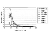
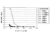
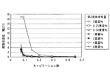
- FIGS. 3 to 6 are graphs showing the relationship between the number of cavitations and vibration acceleration, respectively.
- the horizontal axis of the graph is the cavitation number (dimensionalless amount), and the vertical axis is the vibration acceleration (V).
- the results of the first to fourth verification tests are shown in the order of FIGS.
- the value of the vibration acceleration in each graph is the maximum value among the vibration accelerations measured by the four acceleration sensors.
- Examples 1 to 6 had a tendency for vibration acceleration to be lower than that of the conventional example. Therefore, the working fluid containing the second liquid whose vapor pressure is higher than the main component of the first liquid at the same temperature and less in weight than the first liquid can suppress the magnitude of the shock wave generated at the time of cavitation collapse. confirmed. Further, from the comparison between FIG. 3 and FIG. 4 and the comparison between FIG. 5 and FIG. 6, when the main component of the second liquid is the same, the difference between the vapor pressure of the first liquid and the vapor pressure of the second liquid is large. Thus, it was confirmed that the above-described effects were more effectively achieved.
- a fifth verification test was performed using a working fluid having a different type from any of the working fluids used in the first to fourth verification tests described above.
- the fifth verification test will be described only with respect to differences from the first verification test.
- water was used as the first liquid
- the vapor pressures at 25 ° C. of both liquids are 3173 Pa for water and 280000 Pa for HFE-7100.
- FIG. 7 is a graph showing the relationship between the number of cavitations and vibration acceleration.
- the horizontal axis of the graph is the number of cavitations (dimensionalless amount), and the vertical axis is vibration acceleration (V).
- the value of the vibration acceleration in the graph is the maximum value among the vibration accelerations measured by the four acceleration sensors. From this result, it was confirmed that Examples 1 to 6 had a tendency for vibration acceleration to be lower than that of the conventional example, and it was confirmed that the magnitude of the shock wave generated at the time of cavitation collapse was suppressed.
- the working fluid according to the present invention can suppress the magnitude of a shock wave generated when cavitation collapses.
Landscapes
- Chemical & Material Sciences (AREA)
- Engineering & Computer Science (AREA)
- General Engineering & Computer Science (AREA)
- Mechanical Engineering (AREA)
- Chemical Kinetics & Catalysis (AREA)
- General Chemical & Material Sciences (AREA)
- Oil, Petroleum & Natural Gas (AREA)
- Organic Chemistry (AREA)
- Fluid-Damping Devices (AREA)
- Lubricants (AREA)
- Fluid-Pressure Circuits (AREA)
Abstract
Priority Applications (4)
| Application Number | Priority Date | Filing Date | Title |
|---|---|---|---|
| US13/378,619 US20120126167A1 (en) | 2009-06-17 | 2010-06-17 | Working liquid and device utilizing same |
| EP10789247.3A EP2447345A4 (fr) | 2009-06-17 | 2010-06-17 | Liquide de travail et dispositif l'utilisant |
| JP2011519573A JPWO2010146868A1 (ja) | 2009-06-17 | 2010-06-17 | 作動液およびそれを用いた装置 |
| CN201080036374.9A CN102459532B (zh) | 2009-06-17 | 2010-06-17 | 工作液和使用该工作液的装置 |
Applications Claiming Priority (2)
| Application Number | Priority Date | Filing Date | Title |
|---|---|---|---|
| JP2009144620 | 2009-06-17 | ||
| JP2009-144620 | 2009-06-17 |
Publications (1)
| Publication Number | Publication Date |
|---|---|
| WO2010146868A1 true WO2010146868A1 (fr) | 2010-12-23 |
Family
ID=43356198
Family Applications (1)
| Application Number | Title | Priority Date | Filing Date |
|---|---|---|---|
| PCT/JP2010/004057 Ceased WO2010146868A1 (fr) | 2009-06-17 | 2010-06-17 | Liquide de travail et dispositif l'utilisant |
Country Status (5)
| Country | Link |
|---|---|
| US (1) | US20120126167A1 (fr) |
| EP (1) | EP2447345A4 (fr) |
| JP (1) | JPWO2010146868A1 (fr) |
| CN (1) | CN102459532B (fr) |
| WO (1) | WO2010146868A1 (fr) |
Cited By (2)
| Publication number | Priority date | Publication date | Assignee | Title |
|---|---|---|---|---|
| JP2013227380A (ja) * | 2012-04-24 | 2013-11-07 | Cci Corp | 作動液 |
| JP2022191575A (ja) * | 2021-06-16 | 2022-12-28 | 国立研究開発法人産業技術総合研究所 | 摺動面間の低摩擦構造及びその付与方法 |
Families Citing this family (1)
| Publication number | Priority date | Publication date | Assignee | Title |
|---|---|---|---|---|
| WO2020003012A1 (fr) * | 2018-06-28 | 2020-01-02 | Measurement Specialties, Inc. | Dispositif de détection de pression résistant au vide |
Citations (9)
| Publication number | Priority date | Publication date | Assignee | Title |
|---|---|---|---|---|
| US2751355A (en) * | 1953-06-10 | 1956-06-19 | Studebaker Packard Corp | Transmission fluid |
| JPS4934167B1 (fr) * | 1969-12-16 | 1974-09-12 | ||
| JPS6034541A (ja) | 1983-08-04 | 1985-02-22 | Bridgestone Corp | 弾性ブツシユ |
| JPH0564897A (ja) | 1991-09-09 | 1993-03-19 | Toppan Printing Co Ltd | インクジエツトプリンタのインク加圧機構 |
| JPH09111277A (ja) * | 1995-10-19 | 1997-04-28 | Idemitsu Kosan Co Ltd | 油圧作動油組成物 |
| CN1367231A (zh) * | 2002-03-04 | 2002-09-04 | 赵洪 | 一种水-乙二醇难燃液压液及其制备方法 |
| CN101294116A (zh) * | 2008-06-25 | 2008-10-29 | 邵将 | 独立液压离合器系统用传动液 |
| JP2009036257A (ja) * | 2007-07-31 | 2009-02-19 | Kayaba Ind Co Ltd | 緩衝器 |
| JP2009144620A (ja) | 2007-12-14 | 2009-07-02 | Kawamoto Pump Mfg Co Ltd | 自動給水配管ユニット |
Family Cites Families (6)
| Publication number | Priority date | Publication date | Assignee | Title |
|---|---|---|---|---|
| US3039969A (en) * | 1958-08-29 | 1962-06-19 | Houghton & Co E F | Hydraulic fluid emulsion |
| US3378494A (en) * | 1964-08-07 | 1968-04-16 | Shell Oil Co | Water-in-oil emulsion fluids |
| US5925268A (en) * | 1996-06-06 | 1999-07-20 | Engauge Inc. | Laser welding apparatus employing a tilting mechanism and seam follower |
| US6452121B1 (en) * | 1998-02-11 | 2002-09-17 | Everett Ogden | Three-axis gravity switch having a hemispherical chamber |
| US7435327B2 (en) * | 2004-12-16 | 2008-10-14 | Chevron U.S.A. Inc. | Hydraulic oil with excellent air release and low foaming tendency |
| CN101896733B (zh) * | 2007-12-12 | 2013-12-18 | 株式会社普利司通 | 防振装置 |
-
2010
- 2010-06-17 WO PCT/JP2010/004057 patent/WO2010146868A1/fr not_active Ceased
- 2010-06-17 US US13/378,619 patent/US20120126167A1/en not_active Abandoned
- 2010-06-17 CN CN201080036374.9A patent/CN102459532B/zh not_active Expired - Fee Related
- 2010-06-17 EP EP10789247.3A patent/EP2447345A4/fr not_active Withdrawn
- 2010-06-17 JP JP2011519573A patent/JPWO2010146868A1/ja active Pending
Patent Citations (9)
| Publication number | Priority date | Publication date | Assignee | Title |
|---|---|---|---|---|
| US2751355A (en) * | 1953-06-10 | 1956-06-19 | Studebaker Packard Corp | Transmission fluid |
| JPS4934167B1 (fr) * | 1969-12-16 | 1974-09-12 | ||
| JPS6034541A (ja) | 1983-08-04 | 1985-02-22 | Bridgestone Corp | 弾性ブツシユ |
| JPH0564897A (ja) | 1991-09-09 | 1993-03-19 | Toppan Printing Co Ltd | インクジエツトプリンタのインク加圧機構 |
| JPH09111277A (ja) * | 1995-10-19 | 1997-04-28 | Idemitsu Kosan Co Ltd | 油圧作動油組成物 |
| CN1367231A (zh) * | 2002-03-04 | 2002-09-04 | 赵洪 | 一种水-乙二醇难燃液压液及其制备方法 |
| JP2009036257A (ja) * | 2007-07-31 | 2009-02-19 | Kayaba Ind Co Ltd | 緩衝器 |
| JP2009144620A (ja) | 2007-12-14 | 2009-07-02 | Kawamoto Pump Mfg Co Ltd | 自動給水配管ユニット |
| CN101294116A (zh) * | 2008-06-25 | 2008-10-29 | 邵将 | 独立液压离合器系统用传动液 |
Non-Patent Citations (1)
| Title |
|---|
| See also references of EP2447345A4 * |
Cited By (3)
| Publication number | Priority date | Publication date | Assignee | Title |
|---|---|---|---|---|
| JP2013227380A (ja) * | 2012-04-24 | 2013-11-07 | Cci Corp | 作動液 |
| JP2022191575A (ja) * | 2021-06-16 | 2022-12-28 | 国立研究開発法人産業技術総合研究所 | 摺動面間の低摩擦構造及びその付与方法 |
| JP7744666B2 (ja) | 2021-06-16 | 2025-09-26 | 国立研究開発法人産業技術総合研究所 | 摺動面間の低摩擦構造及びその付与方法 |
Also Published As
| Publication number | Publication date |
|---|---|
| US20120126167A1 (en) | 2012-05-24 |
| JPWO2010146868A1 (ja) | 2012-11-29 |
| CN102459532A (zh) | 2012-05-16 |
| EP2447345A4 (fr) | 2015-09-02 |
| EP2447345A1 (fr) | 2012-05-02 |
| CN102459532B (zh) | 2016-06-08 |
Similar Documents
| Publication | Publication Date | Title |
|---|---|---|
| JP5747045B2 (ja) | 減衰及び慣性油圧装置 | |
| US2535080A (en) | Mounting | |
| JP5452484B2 (ja) | 防振装置 | |
| WO2016147698A1 (fr) | Dispositif d'amortissement de vibrations | |
| WO2010146868A1 (fr) | Liquide de travail et dispositif l'utilisant | |
| JP5150644B2 (ja) | 防振装置 | |
| US9566856B2 (en) | Fluid-filled vibration damping device | |
| KR20090129170A (ko) | 에어 댐핑 엔진 마운트 | |
| JP2014196808A (ja) | 流体封入式防振装置 | |
| US8573061B2 (en) | Pressure indicator | |
| CN205654980U (zh) | 一种基于液压缓冲的减震管卡 | |
| JP5346697B2 (ja) | 防振装置 | |
| CN117366374A (zh) | 一种颗粒阻尼管路吸振器 | |
| CN108644305A (zh) | 一种储液罐减震装置 | |
| JP2008082382A (ja) | 振動伝達抑制装置 | |
| CN211450035U (zh) | 一种高温管道防护装置 | |
| CN112283280A (zh) | 一种应用于快堆钠管系的液压阻尼器 | |
| JP2006258150A (ja) | 弾性受圧粒体を管路に封入した圧力波動減衰装置及び弾性受圧粒体 | |
| JP2012013163A (ja) | 作動流体および防振装置 | |
| JP6106563B2 (ja) | 流体封入式防振装置 | |
| CN118728887A (zh) | 一种可提高阻尼性能的减震结构 | |
| KR101086757B1 (ko) | 진동 방진 장치 | |
| JP6312500B2 (ja) | 防振装置用液体組成物及び液体封入式防振装置 | |
| JP5759360B2 (ja) | 液体封入式防振装置 | |
| JP2021173327A (ja) | 脈動減衰装置 |
Legal Events
| Date | Code | Title | Description |
|---|---|---|---|
| WWE | Wipo information: entry into national phase |
Ref document number: 201080036374.9 Country of ref document: CN |
|
| 121 | Ep: the epo has been informed by wipo that ep was designated in this application |
Ref document number: 10789247 Country of ref document: EP Kind code of ref document: A1 |
|
| WWE | Wipo information: entry into national phase |
Ref document number: 2011519573 Country of ref document: JP |
|
| NENP | Non-entry into the national phase |
Ref country code: DE |
|
| WWE | Wipo information: entry into national phase |
Ref document number: 10368/DELNP/2011 Country of ref document: IN |
|
| REEP | Request for entry into the european phase |
Ref document number: 2010789247 Country of ref document: EP |
|
| WWE | Wipo information: entry into national phase |
Ref document number: 2010789247 Country of ref document: EP |
|
| WWE | Wipo information: entry into national phase |
Ref document number: 13378619 Country of ref document: US |