WO2010146879A1 - 端末装置および再送制御方法 - Google Patents
端末装置および再送制御方法 Download PDFInfo
- Publication number
- WO2010146879A1 WO2010146879A1 PCT/JP2010/004099 JP2010004099W WO2010146879A1 WO 2010146879 A1 WO2010146879 A1 WO 2010146879A1 JP 2010004099 W JP2010004099 W JP 2010004099W WO 2010146879 A1 WO2010146879 A1 WO 2010146879A1
- Authority
- WO
- WIPO (PCT)
- Prior art keywords
- downlink
- unit
- unit band
- terminal
- response signal
- Prior art date
- Legal status (The legal status is an assumption and is not a legal conclusion. Google has not performed a legal analysis and makes no representation as to the accuracy of the status listed.)
- Ceased
Links
Images





Classifications
-
- H—ELECTRICITY
- H04—ELECTRIC COMMUNICATION TECHNIQUE
- H04W—WIRELESS COMMUNICATION NETWORKS
- H04W72/00—Local resource management
- H04W72/20—Control channels or signalling for resource management
- H04W72/23—Control channels or signalling for resource management in the downlink direction of a wireless link, i.e. towards a terminal
-
- H—ELECTRICITY
- H04—ELECTRIC COMMUNICATION TECHNIQUE
- H04L—TRANSMISSION OF DIGITAL INFORMATION, e.g. TELEGRAPHIC COMMUNICATION
- H04L1/00—Arrangements for detecting or preventing errors in the information received
- H04L1/12—Arrangements for detecting or preventing errors in the information received by using return channel
- H04L1/16—Arrangements for detecting or preventing errors in the information received by using return channel in which the return channel carries supervisory signals, e.g. repetition request signals
- H04L1/1607—Details of the supervisory signal
- H04L1/1621—Group acknowledgement, i.e. the acknowledgement message defining a range of identifiers, e.g. of sequence numbers
-
- H—ELECTRICITY
- H04—ELECTRIC COMMUNICATION TECHNIQUE
- H04L—TRANSMISSION OF DIGITAL INFORMATION, e.g. TELEGRAPHIC COMMUNICATION
- H04L1/00—Arrangements for detecting or preventing errors in the information received
- H04L1/12—Arrangements for detecting or preventing errors in the information received by using return channel
- H04L1/16—Arrangements for detecting or preventing errors in the information received by using return channel in which the return channel carries supervisory signals, e.g. repetition request signals
- H04L1/18—Automatic repetition systems, e.g. Van Duuren systems
-
- H—ELECTRICITY
- H04—ELECTRIC COMMUNICATION TECHNIQUE
- H04L—TRANSMISSION OF DIGITAL INFORMATION, e.g. TELEGRAPHIC COMMUNICATION
- H04L1/00—Arrangements for detecting or preventing errors in the information received
- H04L1/12—Arrangements for detecting or preventing errors in the information received by using return channel
- H04L1/16—Arrangements for detecting or preventing errors in the information received by using return channel in which the return channel carries supervisory signals, e.g. repetition request signals
- H04L1/18—Automatic repetition systems, e.g. Van Duuren systems
- H04L1/1829—Arrangements specially adapted for the receiver end
- H04L1/1861—Physical mapping arrangements
-
- H—ELECTRICITY
- H04—ELECTRIC COMMUNICATION TECHNIQUE
- H04L—TRANSMISSION OF DIGITAL INFORMATION, e.g. TELEGRAPHIC COMMUNICATION
- H04L1/00—Arrangements for detecting or preventing errors in the information received
- H04L1/12—Arrangements for detecting or preventing errors in the information received by using return channel
- H04L1/16—Arrangements for detecting or preventing errors in the information received by using return channel in which the return channel carries supervisory signals, e.g. repetition request signals
- H04L1/18—Automatic repetition systems, e.g. Van Duuren systems
- H04L1/1829—Arrangements specially adapted for the receiver end
- H04L1/1864—ARQ related signaling
-
- H—ELECTRICITY
- H04—ELECTRIC COMMUNICATION TECHNIQUE
- H04L—TRANSMISSION OF DIGITAL INFORMATION, e.g. TELEGRAPHIC COMMUNICATION
- H04L5/00—Arrangements affording multiple use of the transmission path
- H04L5/0001—Arrangements for dividing the transmission path
- H04L5/0003—Two-dimensional division
- H04L5/0005—Time-frequency
- H04L5/0007—Time-frequency the frequencies being orthogonal, e.g. OFDM(A) or DMT
- H04L5/001—Time-frequency the frequencies being orthogonal, e.g. OFDM(A) or DMT the frequencies being arranged in component carriers
-
- H—ELECTRICITY
- H04—ELECTRIC COMMUNICATION TECHNIQUE
- H04L—TRANSMISSION OF DIGITAL INFORMATION, e.g. TELEGRAPHIC COMMUNICATION
- H04L5/00—Arrangements affording multiple use of the transmission path
- H04L5/003—Arrangements for allocating sub-channels of the transmission path
- H04L5/0048—Allocation of pilot signals, i.e. of signals known to the receiver
-
- H—ELECTRICITY
- H04—ELECTRIC COMMUNICATION TECHNIQUE
- H04L—TRANSMISSION OF DIGITAL INFORMATION, e.g. TELEGRAPHIC COMMUNICATION
- H04L5/00—Arrangements affording multiple use of the transmission path
- H04L5/003—Arrangements for allocating sub-channels of the transmission path
- H04L5/0053—Allocation of signalling, i.e. of overhead other than pilot signals
-
- H—ELECTRICITY
- H04—ELECTRIC COMMUNICATION TECHNIQUE
- H04L—TRANSMISSION OF DIGITAL INFORMATION, e.g. TELEGRAPHIC COMMUNICATION
- H04L5/00—Arrangements affording multiple use of the transmission path
- H04L5/003—Arrangements for allocating sub-channels of the transmission path
- H04L5/0053—Allocation of signalling, i.e. of overhead other than pilot signals
- H04L5/0055—Physical resource allocation for ACK/NACK
-
- H—ELECTRICITY
- H04—ELECTRIC COMMUNICATION TECHNIQUE
- H04W—WIRELESS COMMUNICATION NETWORKS
- H04W72/00—Local resource management
- H04W72/04—Wireless resource allocation
- H04W72/044—Wireless resource allocation based on the type of the allocated resource
- H04W72/0453—Resources in frequency domain, e.g. a carrier in FDMA
-
- H—ELECTRICITY
- H04—ELECTRIC COMMUNICATION TECHNIQUE
- H04W—WIRELESS COMMUNICATION NETWORKS
- H04W72/00—Local resource management
- H04W72/20—Control channels or signalling for resource management
- H04W72/21—Control channels or signalling for resource management in the uplink direction of a wireless link, i.e. towards the network
-
- H—ELECTRICITY
- H04—ELECTRIC COMMUNICATION TECHNIQUE
- H04W—WIRELESS COMMUNICATION NETWORKS
- H04W74/00—Wireless channel access
- H04W74/002—Transmission of channel access control information
- H04W74/004—Transmission of channel access control information in the uplink, i.e. towards network
-
- H—ELECTRICITY
- H04—ELECTRIC COMMUNICATION TECHNIQUE
- H04W—WIRELESS COMMUNICATION NETWORKS
- H04W76/00—Connection management
- H04W76/20—Manipulation of established connections
- H04W76/28—Discontinuous transmission [DTX]; Discontinuous reception [DRX]
-
- H—ELECTRICITY
- H04—ELECTRIC COMMUNICATION TECHNIQUE
- H04J—MULTIPLEX COMMUNICATION
- H04J13/00—Code division multiplex systems
- H04J13/0007—Code type
- H04J13/0055—ZCZ [zero correlation zone]
- H04J13/0059—CAZAC [constant-amplitude and zero auto-correlation]
- H04J13/0062—Zadoff-Chu
-
- H—ELECTRICITY
- H04—ELECTRIC COMMUNICATION TECHNIQUE
- H04W—WIRELESS COMMUNICATION NETWORKS
- H04W28/00—Network traffic management; Network resource management
- H04W28/02—Traffic management, e.g. flow control or congestion control
- H04W28/04—Error control
-
- H—ELECTRICITY
- H04—ELECTRIC COMMUNICATION TECHNIQUE
- H04W—WIRELESS COMMUNICATION NETWORKS
- H04W84/00—Network topologies
- H04W84/02—Hierarchically pre-organised networks, e.g. paging networks, cellular networks, WLAN [Wireless Local Area Network] or WLL [Wireless Local Loop]
- H04W84/04—Large scale networks; Deep hierarchical networks
- H04W84/042—Public Land Mobile systems, e.g. cellular systems
-
- H—ELECTRICITY
- H04—ELECTRIC COMMUNICATION TECHNIQUE
- H04W—WIRELESS COMMUNICATION NETWORKS
- H04W88/00—Devices specially adapted for wireless communication networks, e.g. terminals, base stations or access point devices
- H04W88/08—Access point devices
Definitions
- the present invention relates to a terminal device and a retransmission control method.
- OFDMA Orthogonal Frequency Division Multiple Access
- SCH Synchronization Channel
- BCH Broadcast Channel
- the terminal first secures synchronization with the base station by capturing the SCH. Thereafter, the terminal acquires parameters (eg, frequency bandwidth) unique to the base station by reading the BCH information (see Non-Patent Documents 1, 2, and 3).
- the terminal establishes communication with the base station by making a connection request to the base station after the acquisition of the parameters unique to the base station is completed.
- the base station transmits control information via a PDCCH (Physical ⁇ Downlink Control CHannel) as necessary to a terminal with which communication has been established.
- PDCCH Physical ⁇ Downlink Control CHannel
- the terminal performs “blind determination” for each of the plurality of control information included in the received PDCCH signal. That is, the control information includes a CRC (Cyclic Redundancy Check) part, and this CRC part is masked by the terminal ID of the transmission target terminal in the base station. Therefore, the terminal cannot determine whether or not the received control information is control information destined for the own device until the CRC part of the received control information is demasked with the terminal ID of the own device. In this blind determination, if the CRC calculation is OK as a result of demasking, it is determined that the control information is addressed to the own device.
- CRC Cyclic Redundancy Check
- ARQ Automatic Repeat Request
- the terminal feeds back a response signal indicating an error detection result of downlink data to the base station.
- An uplink control channel such as PUCCH (Physical Uplink Control Channel) is used for feedback of this response signal (that is, ACK / NACK signal).
- PUCCH Physical Uplink Control Channel
- the control information transmitted from the base station includes resource allocation information including resource information allocated to the terminal by the base station.
- the PDCCH is used for transmitting the control information.
- This PDCCH is composed of one or a plurality of L1 / L2 CCHs (L1 / L2 Control Channel).
- Each L1 / L2CCH is composed of one or a plurality of CCEs (Control Channel Element). That is, CCE is a basic unit for mapping control information to PDCCH.
- one L1 / L2CCH is composed of a plurality of CCEs, a plurality of continuous CCEs are allocated to the L1 / L2CCH.
- the base station allocates L1 / L2 CCH to the resource allocation target terminal according to the number of CCEs required for reporting control information to the resource allocation target terminal. Then, the base station maps the physical resource corresponding to the CCE of this L1 / L2CCH and transmits control information.
- each CCE is associated with the PUCCH configuration resource on a one-to-one basis. Therefore, the terminal that has received the L1 / L2CCH specifies a PUCCH configuration resource corresponding to the CCE that configures the L1 / L2CCH, and transmits a response signal to the base station using this resource.
- the terminal may select one of a plurality of PUCCH configuration resources corresponding to the plurality of CCEs (for example, PUCCH corresponding to the CCE having the smallest Index). The response signal is transmitted to the base station using the configuration resource.
- downlink communication resources are efficiently used.
- a plurality of response signals transmitted from a plurality of terminals include a ZAC (Zero Auto-correlation) sequence having a Zero Auto-correlation characteristic on the time axis, a Walsh sequence, and a DFT ( Discrete Fourier Transform) sequence and code-multiplexed in PUCCH.
- ZAC Zero Auto-correlation
- W 1 , W 2 , W 3 represents a Walsh sequence with a sequence length of 4
- (F 0 , F 1 , F 2 ) represents a DFT sequence with a sequence length of 3.
- an ACK or NACK response signal is first-order spread to a frequency component corresponding to one SC-FDMA symbol by a ZAC sequence (sequence length 12) on the frequency axis.
- the response signal after the first spreading and the ZAC sequence as the reference signal are associated with the Walsh sequence (sequence length 4: W 0 to W 3 ) and the DFT sequence (sequence length 3: F 0 to F 3 ), respectively.
- the second-order spread signal is converted into a signal having a sequence length of 12 on the time axis by IFFT (Inverse Fast Fourier Transform).
- IFFT Inverse Fast Fourier Transform
- the orthogonal code sequence is a set of a Walsh sequence and a DFT sequence.
- the orthogonal code sequence may be referred to as a block-wise spreading code sequence. Therefore, the base station can separate these response signals that have been code-multiplexed by using conventional despreading and correlation processing (see Non-Patent Document 4).
- each terminal blindly determines the downlink allocation control signal addressed to itself in each subframe, reception of the downlink allocation control signal is not always successful on the terminal side.
- a terminal fails to receive a downlink assignment control signal addressed to itself in a certain downlink unit band, the terminal cannot even know whether downlink data addressed to itself exists in the downlink unit band. Therefore, if reception of a downlink assignment control signal in a certain downlink unit band fails, the terminal does not generate a response signal for downlink data in the downlink unit band.
- This error case is defined as DTX (DTX (Discontinuous transmission) of ACK / NACK signals) of the response signal in the sense that the response signal is not transmitted on the terminal side.
- LTE-A system 3GPP LTE-advanced system
- LTE system 3GPP LTE system
- the LTE- The band for the A system is divided into “unit bands” of 20 MHz or less, which is the support bandwidth of the LTE system. That is, the “unit band” is a band having a maximum width of 20 MHz, and is defined as a basic unit of the communication band. Furthermore, the “unit band” (hereinafter referred to as “downlink unit band”) in the downlink is a band delimited by downlink frequency band information in the BCH broadcast from the base station, or the downlink control channel (PDCCH) is a frequency.
- the “unit band” hereinafter referred to as “downlink unit band” in the downlink is a band delimited by downlink frequency band information in the BCH broadcast from the base station, or the downlink control channel (PDCCH) is a frequency.
- the “unit band” in the uplink is a band delimited by uplink frequency band information in the BCH broadcast from the base station, or a PUSCH (Physical-Uplink) near the center. It may be defined as a basic unit of a communication band of 20 MHz or less including a Shared (CHAnel) region and including PUCCH for LTE at both ends.
- the “unit band” may be expressed as “Component Carrier (s)” in English in 3GPP LTE-Advanced.
- the LTE-A system supports communication using a band obtained by bundling several unit bands, so-called Carrier Aggregation.
- Carrier Aggregation In general, an uplink throughput request and a downlink throughput request are different from each other. Therefore, in the LTE-A system, an arbitrary LTE-A system compatible terminal (hereinafter referred to as “LTE-A terminal”) is set.
- LTE-A terminal an arbitrary LTE-A system compatible terminal
- Carrier-aggregation the so-called Asymmetric carrier-aggregation, in which the number of unit bands to be transmitted differs between upstream and downstream, is also being studied. Furthermore, the case where the number of unit bands is asymmetric between upstream and downstream and the frequency bandwidth of each unit band is different is also supported.
- FIG. 2 is a diagram for explaining an asymmetric carrier aggregation applied to individual terminals and its control sequence.
- FIG. 2 shows an example in which the uplink and downlink bandwidths and the number of unit bands of the base station are symmetric.
- terminal 1 is configured to perform carrier aggregation using two downlink unit bands and one uplink unit band on the left side. In spite of the setting that uses the same two downlink unit bands as those of the terminal 1, the setting that uses the right uplink unit band is performed in the uplink communication.
- Terminal 1 When attention is paid to the terminal 1, signals are transmitted and received between the LTE-A base station and the LTE-A terminal constituting the LTE-A system according to the sequence diagram shown in FIG. 2A.
- Terminal 1 synchronizes with the left downlink unit band at the start of communication with the base station, and sends information on the uplink unit band paired with the left downlink unit band to SIB2 Read from a notification signal called (System Information Block Type 2).
- SIB2 System Information Block Type 2
- the terminal 1 starts communication with the base station, for example, by transmitting a connection request to the base station.
- the base station instructs the terminal to add a downlink unit band.
- the number of uplink unit bands does not increase, and asymmetric carrier aggregation is started in terminal 1, which is an individual terminal.
- a terminal may receive a plurality of downlink data in a plurality of downlink unit bands at a time.
- Channel Selection also referred to as Multiplexing
- Channel-Selection not only symbols used for response signals but also resources for mapping response signals are changed according to the pattern of error detection results for a plurality of downlink data. That is, as shown in FIG. 3, the Channel selection is based on whether the response signal for the plurality of downlink data received in the plurality of downlink unit bands is ACK or NACK, respectively (ie, Constellation point). This is a technique for changing not only the resources used for transmission of response signals but also non-patent documents 5 and 6.
- a unit band group (which may be expressed as “Component carrier set” in English) composed of downlink unit bands 1 and 2 and uplink unit band 1 is set for terminal 1.
- downlink resource allocation information is transmitted from the base station to the terminal 1 via the PDCCH of each of the downlink unit bands 1 and 2, downlink data is transmitted using resources corresponding to the downlink resource allocation information.
- a response signal is mapped to a PUCCH resource included in the PUCCH region 1, and a first phase point (for example, a phase point such as (1,0)) is used as a phase point of the response signal.
- a first phase point for example, a phase point such as (1,0)
- the response signal is mapped to the PUCCH resource included in PUCCH region 2, and A first phase point is used. That is, when there are two downlink unit bands, there are four patterns of error detection results, and therefore, these four patterns can be represented by a combination of two resources and two types of phase points.
- the base station side secures a plurality of PUCCH resources for any terminal. I have to leave.
- the downlink unit band 1 and the uplink unit band 1 in FIG. 3 are associated with each other to form a band pair, and the downlink unit band 2 and the uplink unit band 2 are associated with each other to form a band pair. Therefore, it suffices if a PUCCH corresponding to the downlink unit band 2 is prepared only for the uplink unit band 2.
- the downlink unit band 2 and the uplink unit band 1 are associated with the unit band unique to the LTE-A terminal. Therefore, it is necessary to secure the PUCCH resource for the response signal for the downlink unit band 2 even in the uplink unit band 1. That is, the uplink control channel (PUCCH) of the uplink unit band 1 needs to be provided with an additional region (PUCCH region 2) in addition to the basic region (PUCCH region 1).
- An object of the present invention is to avoid degradation of response signal transmission characteristics and to perform uplink control when ARQ is applied in communication using an uplink unit band and a plurality of downlink unit bands associated with the uplink unit band. To provide a terminal device and a retransmission control method capable of minimizing an increase in channel overhead.
- the terminal apparatus communicates with a base station using a unit band group including a plurality of downlink unit bands and an uplink unit band, and detects an error detection result of a plurality of downlink data arranged in the plurality of downlink unit bands.
- a terminal device that transmits one bundle response signal on the uplink control channel of the uplink unit band based on the downlink that receives downlink data transmitted on at least one downlink data channel of the plurality of downlink unit bands Based on a reception status pattern determined by an error detection result obtained by the data receiving means, an error detection means for detecting the reception error of the received downlink data, and the error detecting means, the number of the uplink control channel Response control means for transmitting the bundle response signal using either the first area or the second area, and the response control means
- the bundle response signal is transmitted using the resource in the first area, and in the case of a reception situation pattern with a low occurrence probability, the bundle is used using the resource in the second area.
- Send a response signal In the case of a high reception situation pattern, the bundle response signal is transmitted using the resource in the first area, and in the case of a reception situation pattern with a low occurrence probability, the bundle is used using the resource in the second area. Send a response signal.
- the retransmission control method of the present invention includes a downlink data reception step of receiving downlink data transmitted on at least one downlink data channel of a plurality of downlink unit bands included in a unit band group, and the received downlink data Based on an error detection step for detecting a reception error and a reception status pattern determined by an error detection result obtained in the error detection step, the first region and the first region of the uplink control channel in the uplink unit band included in the unit band group A response control step of transmitting a bundle response signal using one of the two regions, and in the response control step, in the case of a reception situation pattern with a high probability of occurrence, the resources of the first region are used. When the bundle response signal is transmitted and the reception status pattern has a low probability of occurrence, the resource of the second area The bundle response signal is transmitted using.
- diffusion method of a response signal and a reference signal Diagram for explaining asymmetric Carrier Car aggregation and its control sequence applied to individual terminals The figure which serves for explanation of ARQ control when Carrier aggregation is applied to the terminal.
- Diagram for explaining operation of base station and terminal Diagram for explaining operation of base station and terminal The figure where it uses for description of operation
- the base station 100 is configured to be able to support both communication using asymmetric carrier aggregation and communication not using carrier aggregation.
- communication that does not depend on Carrier aggregation can be performed between the base station 100 and the terminal 200 depending on resource allocation to the terminal 200 by the base station 100.
- this communication system when communication not based on Carrier aggregation is performed, ARQ is performed as usual, whereas when communication based on Carrier aggregation is performed, Channel Selection is employed in ARQ. That is, this communication system is, for example, an LTE-A system, the base station 100 is, for example, an LTE-A base station, and the terminal 200 is, for example, an LTE-A terminal. Moreover, the terminal which does not have the capability to perform communication by Carrier aggregation is, for example, an LTE terminal.
- an asymmetric carrier aggregation unique to the terminal 200 is configured in advance between the base station 100 and the terminal 200, and information on the downlink unit band and the uplink unit band to be used by the terminal 200 is obtained between the base station 100 and the terminal 200. Shared between. Further, a downlink unit in which a BCH for transmitting information on uplink unit bands constituting a unit band group configured (configured) by the base station 100 for an arbitrary terminal 200 and notified to the terminal 200 in advance is transmitted.
- the band is a “basic unit band” for the terminal 200.
- Information on the basic unit band is “basic unit band information”. Therefore, any terminal 200 can recognize the basic unit band information by reading the BCH information in each downlink unit band.
- FIG. 4 is a block diagram showing a configuration of base station 100 according to Embodiment 1 of the present invention.
- a base station 100 includes a control unit 101, a control information generation unit 102, an encoding unit 103, a modulation unit 104, a broadcast signal generation unit 105, an encoding unit 106, and a data transmission control unit 107.
- 116 sequence control section 117, correlation processing section 118, determination section 119, and retransmission control signal generation section 120.
- the control unit 101 transmits, to the resource allocation target terminal 200, downlink resources for transmitting control information (that is, downlink control information allocation resources) and downlink data included in the control information.
- Assign (assign) downlink resources (that is, downlink data allocation resources).
- This resource allocation is performed in the downlink unit band included in the unit band group set in the resource allocation target terminal 200.
- the downlink control information allocation resource is selected in a resource corresponding to a downlink control channel (PDCCH) in each downlink unit band.
- the downlink data allocation resource is selected in a resource corresponding to a downlink data channel (PDSCH) in each downlink unit band.
- the control unit 101 allocates different resources to each of the resource allocation target terminals 200.
- the downlink control information allocation resource is equivalent to the above-mentioned L1 / L2CCH. That is, the downlink control information allocation resource is composed of one or a plurality of CCEs.
- each CCE in the basic unit band is associated one-to-one with the configuration resource of the uplink control channel region (PUCCH region) in the uplink unit band in the unit band group.
- control unit 101 determines a coding rate used when transmitting control information to the resource allocation target terminal 200. Since the data amount of control information differs according to the coding rate, downlink control information allocation resources having a number of CCEs to which control information of this data amount can be mapped are allocated by the control unit 101.
- control unit 101 generates DAI (Downlink Assignment Indicator) that is information indicating in which downlink unit band the downlink resource is allocated to the resource allocation target terminal 200.
- DAI Downlink Assignment Indicator
- control part 101 outputs the information regarding a downlink data allocation resource, and DAI with respect to the control information generation part 102 with respect to the control information generation part 102.
- FIG. the control unit 101 outputs information on the coding rate to the coding unit 103.
- Control unit 101 also determines the coding rate of transmission data (that is, downlink data) and outputs the coding rate to coding unit 106.
- the control unit 101 outputs information on downlink data allocation resources and downlink control information allocation resources to the mapping unit 109. However, the control unit 101 performs control so that downlink data and downlink control information for the downlink data are mapped to the same downlink unit band.
- control unit 101 determines, for the broadcast signal generation unit 105, the maximum number of PUCCH signals that are code-multiplexed per unit time frequency resource (1 resource block: 1RB (Resource Block)) arranged in each PUCCH region. Output information about numbers (ie, multiplicity information). Further, the control unit 101 outputs a control signal for generating a broadcast channel signal (BCH) to be transmitted to the broadcast signal generation unit 105. Control of the number of PUCCH resources per unit time frequency resource in each PUCCH region will be described in detail later.
- the control information generation unit 102 generates information related to downlink data allocation resources and control information including DAI, and outputs the control information to the encoding unit 103.
- This control information is generated for each downlink unit band.
- the control information includes the terminal ID of the destination terminal in order to distinguish the resource allocation target terminals 200 from each other. For example, CRC bits masked with the terminal ID of the destination terminal are included in the control information.
- This control information may be referred to as “downlink allocation control information”.
- the DAI is included in all control information for the resource allocation target terminal 200.
- the encoding unit 103 encodes the control information according to the encoding rate received from the control unit 101, and outputs the encoded control information to the modulation unit 104.
- Modulation section 104 modulates the encoded control information and outputs the obtained modulated signal to mapping section 109.
- the notification signal generation unit 105 generates a notification signal (BCH) for each downlink unit band according to the information received from the control unit 101 and the control signal, and outputs the notification signal (BCH) to the mapping unit 109.
- BCH notification signal
- Encoding section 106 receives transmission data (that is, downlink data) for each destination terminal 200 and encoding rate information from control section 101 as input, encodes the transmission data, and outputs the encoded transmission data to data transmission control section 107. However, when a plurality of downlink unit bands are allocated to destination terminal 200, the transmission data transmitted in each downlink unit band is encoded, and the encoded transmission data is output to data transmission control section 107. .
- the data transmission control unit 107 holds the encoded transmission data and outputs it to the modulation unit 108 at the time of initial transmission.
- the encoded transmission data is held for each destination terminal 200. Transmission data to one destination terminal 200 is held for each downlink unit band to be transmitted. As a result, not only retransmission control of the entire data transmitted to the destination terminal 200 but also retransmission control for each downlink unit band is possible.
- data transmission control section 107 when data transmission control section 107 receives NACK or DTX for downlink data transmitted in a certain downlink unit band from retransmission control signal generation section 120, data transmission control section 107 outputs retained data corresponding to this downlink unit band to modulation section 108. .
- the data transmission control unit 107 receives an ACK for downlink data transmitted in a certain downlink unit band from the retransmission control signal generation unit 120, the data transmission control unit 107 deletes the retained data corresponding to the downlink unit band.
- Modulation section 108 modulates the encoded transmission data received from data transmission control section 107, and outputs the modulated signal to mapping section 109.
- the mapping unit 109 maps the modulation signal of the control information received from the modulation unit 104 to the resource indicated by the downlink control information allocation resource received from the control unit 101, and outputs it to the IFFT unit 110.
- mapping section 109 maps the modulation signal of the transmission data received from modulation section 108 to the resource indicated by the downlink data allocation resource received from control section 101 and outputs it to IFFT section 110.
- mapping unit 109 maps broadcast information to predetermined time / frequency resources and outputs the information to the IFFT unit 110.
- Control information, transmission data, and broadcast signals mapped to a plurality of subcarriers in a plurality of downlink unit bands by mapping section 109 are converted from frequency domain signals to time domain signals by IFFT section 110, and are then sent to CP adding section 111.
- the wireless transmission unit 112 After the CP is added to the OFDM signal, the wireless transmission unit 112 performs transmission processing such as D / A conversion, amplification and up-conversion, and transmits the signal to the terminal 200 via the antenna.
- the wireless reception unit 113 receives the response signal or the reference signal transmitted from the terminal 200 via the antenna, and performs reception processing such as down-conversion and A / D conversion on the response signal or the reference signal.
- the CP removal unit 114 removes the CP added to the response signal or the reference signal after reception processing.
- the PUCCH extraction unit 115 extracts the uplink control channel signal included in the received signal for each PUCCH region, and distributes the extracted signal.
- the uplink control channel signal may include a response signal and a reference signal transmitted from the terminal 200.
- the despreading unit 116-N, the correlation processing unit 118-N, and the determination unit 119-N process the uplink control channel signal extracted in the PUCCH region N.
- Base station 100 is provided with a processing system of despreading section 116, correlation processing section 118, and determination section 119 corresponding to each of PUCCH regions 1 to N used by base station 100.
- despreading section 116 despreads the signal corresponding to the response signal in the orthogonal code sequence that terminal 200 should use for secondary spreading in each PUCCH region, and performs correlation processing on the signal after despreading To the unit 118. Further, despreading section 116 despreads the signal corresponding to the reference signal in the orthogonal code sequence that terminal 200 should use for spreading the reference signal in each uplink unit band, and the signal after despreading is the correlation processing section. It outputs to 118.
- the sequence control unit 117 generates a ZAC sequence that may be used for spreading the response signal and the reference signal transmitted from the terminal 200.
- sequence control section 117 determines a correlation window in which the signal component from terminal 200 should be included in each of PUCCH regions 1 to N based on code resources (for example, cyclic shift amount) that terminal 200 may use. Identify.
- Sequence control section 117 then outputs information indicating the identified correlation window and the generated ZAC sequence to correlation processing section 118.
- Correlation processing section 118 may use the signal input from despreading section 116 and the first spreading in terminal 200 using the information indicating the correlation window input from sequence control section 117 and the ZAC sequence. A correlation value with the ZAC sequence is obtained and output to the determination unit 119.
- determination section 119 Based on the correlation value input from correlation processing section 118, determination section 119 indicates whether the response signal transmitted from the terminal indicates either ACK or NACK for the data transmitted in each downlink unit band. Or whether it is DTX. That is, if the magnitude of the correlation value input from the correlation processing unit 118 is equal to or smaller than a certain threshold, the determination unit 119 determines that the terminal 200 has not transmitted ACK or NACK using the resource, and the correlation value If the magnitude of is greater than or equal to the threshold, it is further determined by synchronous detection which phase point the response signal indicates. Then, determination section 119 outputs the determination result in each PUCCH region to retransmission control signal generation section 120.
- the retransmission control signal generation unit 120 determines whether or not the data transmitted in each downlink unit band should be retransmitted based on the information input from the determination unit 119, and generates a retransmission control signal based on the determination result.
- retransmission control signal generation section 120 determines in which PUCCH region corresponding to determination sections 119-1 through 11-N the maximum correlation value has been detected.
- an ACK signal or NACK signal for data transmitted in each downlink unit band is individually generated depending on which phase point the response signal transmitted in the PUCCH region in which the maximum correlation value is detected indicates. And output to the data transmission control unit 107.
- retransmission control signal generation section 120 determines that no response signal is transmitted from terminal 200, and transmits all downlink data.
- DTX is generated and output to the data transmission control unit 107.
- FIG. 5 is a block diagram showing a configuration of terminal 200 according to Embodiment 1 of the present invention.
- terminal 200 includes radio reception section 201, CP removal section 202, FFT section 203, extraction section 204, broadcast signal reception section 205, demodulation section 206, decoding section 207, and determination section 208.
- the radio reception unit 201 receives an OFDM signal transmitted from the base station 100 via an antenna, and performs reception processing such as down-conversion and A / D conversion on the received OFDM signal.
- CP removing section 202 removes the CP added to the OFDM signal after reception processing.
- the FFT unit 203 performs FFT on the received OFDM signal and converts it into a frequency domain signal, and outputs the obtained received signal to the extracting unit 204.
- the extraction unit 204 extracts a notification signal from the reception signal received from the FFT unit 203 and outputs the notification signal to the notification signal reception unit 205. Since the resource to which the broadcast signal is mapped is determined in advance, the extraction unit 204 extracts information mapped to the resource. Also, the extracted broadcast signal includes information related to the association between each downlink unit band and the uplink unit band, and information related to the number of PUCCH resources included in each PUCCH region.
- the extraction unit 204 extracts a downlink control channel signal (PDCCH signal) from the received signal received from the FFT unit 203 according to the input coding rate information. That is, since the number of CCEs constituting the downlink control information allocation resource changes according to the coding rate, the extraction unit 204 extracts the downlink control channel signal using the number of CCEs corresponding to the coding rate as an extraction unit. . Further, the downlink control channel signal is extracted for each downlink unit band. The extracted downlink control channel signal is output to demodulation section 206.
- PDCCH signal downlink control channel signal
- the extraction unit 204 extracts downlink data from the received signal based on the information regarding the downlink data allocation resource addressed to the own device received from the determination unit 208 and outputs the downlink data to the demodulation unit 210.
- the broadcast signal receiving unit 205 decodes each broadcast signal included in each downlink unit band, and is notified by information on uplink unit bands that form a pair with each downlink unit band (ie, SIB2 mapped to each downlink unit band). Information on the upstream unit band). Also, the broadcast signal receiving unit 205 recognizes the downlink unit band paired with the uplink unit band included in the unit band group for the own device as the “basic unit band”, and determines the basic unit band information by the determination unit 208 and the control unit. Output to the unit 209.
- the broadcast signal receiving unit 205 is configured to provide information on the number of code multiplexes in each PUCCH region prepared corresponding to each downlink unit band (that is, how many PUCCH resources are defined per unit time frequency resource in each PUCCH region). Information (multiplicity information)) is extracted and output to the control unit 209.
- the demodulating unit 206 demodulates the downlink control channel signal received from the extracting unit 204 and outputs the obtained demodulation result to the decoding unit 207.
- the decoding unit 207 decodes the demodulation result received from the demodulation unit 206 according to the input coding rate information, and outputs the obtained decoding result to the determination unit 208.
- the determination unit 208 identifies the CCE to which the control information addressed to the above-described device is mapped in the downlink control channel of the basic unit band, and outputs the identified CCE identification information to the control unit 209.
- the control unit 209 specifies the PUCCH resource (frequency / code) corresponding to the CCE indicated by the CCE identification information received from the determination unit 208. That is, the control unit 209 specifies a PUCCH resource (that is, “basic PUCCH resource”) in the basic region of the uplink control channel based on the CCE identification information. However, the control unit 209 holds in advance information related to the PUCCH resource (that is, “additional PUCCH resource”) in the additional region for Channel selection, which is notified from the base station 100 to the terminal 200.
- control unit 209 uses which of the basic PUCCH resource and the additional PUCCH resource to transmit the response signal. decide. That is, the control unit 209 determines which one of the basic PUCCH resource and the additional PUCCH resource is used for transmission of the response signal according to an error detection result pattern regarding a plurality of downlink data. Further, the control unit 209 determines which phase point is set in the response signal based on the reception success / failure situation of the downlink data in each downlink unit band input from the CRC unit 212.
- control unit 209 outputs information on the phase point to be set to the response signal generation unit 213, outputs the ZAC sequence corresponding to the PUCCH resource to be used and the cyclic shift amount to the primary spreading unit 215, and the frequency resource. Information is output to IFFT section 217. Also, the control unit 209 outputs an orthogonal code sequence corresponding to the PUCCH resource to be used to the secondary spreading unit 216. Details of control of the PUCCH resource and the phase point by the control unit 209 will be described later.
- Demodulation section 210 demodulates the downlink data received from extraction section 204 and outputs the demodulated downlink data to decoding section 211.
- Decoding section 211 decodes the downlink data received from demodulation section 210, and outputs the decoded downlink data to CRC section 212.
- the response signal generation unit 213 generates a response signal and a reference signal based on the phase point of the response signal instructed from the control unit 209, and outputs the response signal and the reference signal to the modulation unit 214.
- Modulation section 214 modulates the response signal input from response signal generation section 213 and outputs it to primary spreading section 215.
- the primary spreading unit 215 performs first spreading of the response signal and the reference signal based on the ZAC sequence and the cyclic shift amount set by the control unit 209, and the response signal and the reference signal after the first spreading are processed by the secondary spreading unit 216. Output to. That is, primary spreading section 215 performs primary spreading of the response signal and the reference signal in accordance with an instruction from control section 209.
- Secondary spreading section 216 performs second spreading of the response signal and reference signal using the orthogonal code sequence set by control section 209, and outputs the signal after the second spreading to IFFT section 217. That is, the second spreading section 216 performs second spreading on the response signal and reference signal after the first spreading using the orthogonal code sequence corresponding to the PUCCH resource selected by the control section 209, and the spread signal is the IFFT section. To 217.
- CP adding section 218 adds the same signal as the tail part of the signal after IFFT to the head of the signal as CP.
- the wireless transmission unit 219 performs transmission processing such as D / A conversion, amplification, and up-conversion on the input signal. Then, the wireless transmission unit 219 transmits a signal from the antenna to the base station 100.
- FIG. 1 [Operations of base station 100 and terminal 200] The operations of base station 100 and terminal 200 having the above configuration will be described. 6 and 7 are diagrams for explaining operations of the base station 100 and the terminal 200. FIG.
- control section 101 sets the multiplicity of PUCCH signals independently in each PUCCH region.
- PUCCH region 1 that is, a region where a response signal from an LTE terminal and a response signal from an LTE-A terminal coexist
- 18 PUCCH resources # 1 to 18 per unit time frequency resource are included. Is defined.
- the PUCCH region 2 that is, the additional PUCCH region notified to the LTE-A terminal
- 36 PUCCH resources # 1 to 36 are defined per unit time frequency resource.
- a basic PUCCH resource for terminal 200 is included in PUCCH region 1, and an additional PUCCH resource for terminal 200 is included in PUCCH region 2.
- the base station 100 sets the multiplicity per unit time frequency resource independently for each PUCCH region. Specifically, this multiplicity is specified by the number of positions used among positions that can be taken as the cyclic shift amount. More specifically, it is specified by how many positions are used. In FIG. 7, 12 positions can be taken for one series. In PUCCH region 1, sequences corresponding to every other cyclic shift amount (Cyclic shift index) are used, and in PUCCH region 2, cyclic shift sequences corresponding to all twelve cyclic shift amounts are used. Has been. That is, in the PUCCH region 2, every zero position is used. Therefore, in FIG. 7, 18 PUCCH resources are prepared in the PUCCH region 1, while 36 PUCCH resources are prepared in the PUCCH region 2. That is, the PUCCH region 2 has more boxes (that is, PUCCH resources) in which the PUCCH signal can be put than the PUCCH region 1.
- this multiplicity is specified by the number of positions used among positions that can be taken as the cyclic shift amount. More specifically, it is
- the PUCCH resources in the PUCCH region 1 are associated with the CCEs in the basic unit band on a one-to-one basis, and information regarding this association is shared between the base station 100 and the terminal 200 in advance.
- broadcast signal receiving section 205 identifies a downlink unit band in which BCH for broadcasting information related to an uplink unit band constituting a unit band group notified to terminal 200 is transmitted as a basic unit band.
- the determination unit 208 determines whether or not downlink allocation control information addressed to itself is included in the downlink control channel of each downlink unit band, and outputs the downlink allocation control information addressed to itself to the extraction unit 204.
- the extraction unit 204 extracts downlink data from the received signal based on the downlink allocation control information received from the determination unit 208.
- terminal 200 can receive downlink data transmitted from base station 100.
- the BCH that broadcasts information related to the uplink unit band 1 is transmitted in the downlink unit band 1, so the downlink unit band 1 becomes the basic unit band of the terminal 200.
- the downlink allocation control information transmitted in the downlink unit band 1 includes information on resources used for transmission of downlink data (DL data) transmitted in the downlink unit band 1, and is transmitted in the downlink unit band 2.
- the downlink allocation control information to be included includes information on resources used for transmission of downlink data transmitted in the downlink unit band 2.
- the terminal 200 receives the downlink allocation control information transmitted in the downlink unit band 1 and the downlink allocation control information transmitted in the downlink unit band 2, so that the terminal 200 downloads in both the downlink unit band 1 and the downlink unit band 2.
- Line data can be received.
- the terminal cannot receive downlink allocation control information in a certain downlink unit band, terminal 200 cannot receive downlink data in the downlink unit band.
- the terminal 200 can recognize the downlink unit band in which the downlink allocation control information is transmitted by the DAI transmitted in each downlink unit band.
- CRC section 212 performs error detection on downlink data corresponding to downlink allocation control information that has been successfully received, and outputs an error detection result to control section 209.
- control unit 209 performs transmission control of the response signal as follows.
- the control unit 209 indicates that the error detection result for downlink data transmitted in the basic unit band and the error detection result for downlink data transmitted in other than the basic unit band are both “error”.
- the response signal is transmitted using the basic PUCCH resource (that is, the resource of PUCCH region 1).
- the basic PUCCH resource is determined in association with the CCE occupied by the downlink allocation control information transmitted to the terminal 200 in the basic unit band.
- control unit 209 determines that the error detection result regarding the downlink data transmitted in the basic unit band and the error detection result regarding the downlink data transmitted other than the basic unit band are both “error present” (that is, In the case of NACK / NACK), a response signal is transmitted using an additional PUCCH resource (that is, a resource of PUCCH region 2).
- an additional PUCCH resource that is, a resource of PUCCH region 2).
- the information on the additional PUCCH resource is shared between the base station 100 and the terminal 200 in advance as described above.
- response signals corresponding to two error detection result patterns are mapped to the basic PUCCH resource and the additional PUCCH resource, respectively. Therefore, BPSK having two phase points is used.
- the terminal receives a downlink assignment control signal in a part of a plurality of downlink unit bands, the terminal recognizes that downlink data is assigned in other downlink unit bands by the DAI included therein. If downlink data cannot be received due to failure to receive downlink allocation control signals in other downlink unit bands (that is, if DTX occurs in other downlink unit bands), reception of downlink allocation control signals is performed. Are handled in the same manner as in the case of “with error” in the downlink unit band that has failed.
- the base station controls the downlink data coding rate and modulation method so that the assumed downlink data error rate (Target Block Error: Target BLER) is about 0% to 30%. (Operation with an assumed error rate of about 10% is most typical).
- Target Block Error Target BLER
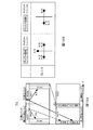
- the possibility that the error detection result for downlink data on the terminal side becomes “no error” is higher than the possibility that “error is present”. That is, as shown in FIG. 6, when there are two downlink unit bands included in a unit band group, the probability that no error is detected in both downlink data transmitted in each downlink unit band is about 81%, The probability that an error will be detected is about 1%.
- the error in the basic region associated with the downlink control channel of the basic unit band is detected.
- a resource is used to transmit a bundle response signal (that is, a response signal in which the resource used and phase point are determined by the operation of Channel Selection), and errors are detected in all
- the resource in the additional region is used.
- the frequency with which the additional area is used can be kept low.
- the multiplicity in the unit time frequency resource included in the additional region is increased in order to minimize the increase in overhead due to the additional region, the frequency with which the bundle response signal is mapped to the additional region is kept small. Therefore, an increase in intersymbol interference is also suppressed. In this way, it is possible to avoid degradation of the response signal transmission characteristics and to minimize an increase in the overhead of the uplink control channel.
- the maximum number of code multiplexes can be increased in order to significantly reduce the number of time frequency resources occupied by the PUCCH region (that is, PUCCH region 2) that is additionally required for the LTE system in the LTE-A system.
- Decrease the probability that the additional PUCCH resource is used that is, use the basic PUCCH resource when all downlink data is “no error”, and add the PUCCH resource when all downlink data is “error”.
- control unit 209 when error is not detected in all of the plurality of downlink data in the unit band group, control unit 209 relates to the uplink unit band in the unit band group.
- a bundle response signal is transmitted using resources in the basic region of the uplink control channel in the uplink unit band, which is associated with the downlink control channel of the basic unit band that is the downlink unit band in which the broadcast channel signal including the information is transmitted.
- a bundle response signal is transmitted using resources in the additional region of the uplink control channel.
- the frequency with which the bundle response signal is mapped to the additional area can be made smaller than that of the basic area. Since the frequency with which the bundle response signal is mapped to the additional region can be kept small, the increase in the multiplicity of the additional region and the increase in overhead due to the additional region can be minimized while preventing an increase in intersymbol interference. Can be suppressed.
- the present invention is not limited to this, and the additional PUCCH resource is defined in association with the CCE occupied by the downlink allocation control information transmitted in other than the basic unit band, similarly to the basic PUCCH resource. (That is, Implicit additional PUCCH resource signaling may be applied). By doing so, the signaling overhead related to the additional PUCCH resource can be reduced.
- a plurality of CCEs other than the basic unit band may be associated with one additional PUCCH resource.
- the number of additional PUCCH resources to be defined in the additional region of the uplink control channel is reduced to the number of CCEs / m, and thus the PUCCH overhead is further reduced.
- the present invention is not limited to this, and part or all of the basic area and the additional area may overlap.
- the base station controls the basic PUCCH resource and the additional PUCCH resource that a certain terminal should recognize in a certain subframe. In this way, the base station 100 prepares the basic area and the additional area in an overlapping manner, whereby the PUCCH overhead in this system is reduced to the same level as in the LTE system.
- sequences that can be separated from each other by different cyclic shift amounts other than the ZAC sequence may be used for the first spreading.
- GCL Generalized Chirp like
- CAZAC Constant Amplitude Zero Auto Correlation
- ZC Zero Auto Correlation
- PN sequence such as M sequence and orthogonal gold code sequence
- time randomly generated by a computer A sequence having a sharp autocorrelation characteristic on the axis may be used for the first spreading.
- any sequence may be used as the orthogonal code sequence as long as the sequences are orthogonal to each other or sequences that can be regarded as being substantially orthogonal to each other.
- a Walsh sequence or a Fourier sequence can be used for quadratic spreading as an orthogonal code sequence.
- the response signal resource (for example, PUCCH resource) is defined by the cyclic shift amount of the ZAC sequence and the sequence number of the orthogonal code sequence.
- Embodiment 2 In the first embodiment, when the terminal generates the response signal, the case where the reception of the downlink data is failed and the case where the reception of the downlink allocation control signal is failed are described as being handled in the same manner.
- Embodiment 2 when a terminal generates a response signal, it is distinguished from a case where reception of downlink data fails and a case where reception of a downlink assignment control signal fails.
- the base station can distinguish whether the terminal has failed to receive the downlink data of each unit band or has failed to receive the downlink assignment control signal. Control becomes possible.
- Embodiment 2 The configuration of the base station and terminal according to Embodiment 2 is the same as that of Embodiment 1, and will be described with reference to FIGS. 4 and 5.
- control section 209 determines basic PUCCH resources and additional PUCCH resources according to reception success / failure patterns of a plurality of downlink allocation control signals and error detection result patterns regarding a plurality of downlink data. Of which is used to transmit the response signal.
- control unit 209 performs response signal transmission control as follows based on the pattern of successful reception of a plurality of downlink assignment control signals and the pattern of error detection results regarding a plurality of downlink data.
- the control unit 209 receives downlink assignment control information in the basic unit band and other downlink unit bands other than the basic unit band, and transmits downlink data transmitted in the basic unit band and downlink transmitted in other than the basic unit band.
- a response signal is transmitted using the basic PUCCH resource.
- the basic PUCCH resource is determined in association with the CCE occupied by the downlink allocation control information transmitted to the terminal 200 in the basic unit band.
- control unit 209 receives downlink allocation control information in the basic unit band and other downlink unit bands, and the downlink data transmitted in the basic unit band is “no error” and transmitted in other than the basic unit band.
- the response signal is transmitted using the basic PUCCH resource.
- control unit 209 receives downlink allocation control information in the basic unit band and other downlink unit bands, and the downlink data transmitted in the basic unit band is “error present” and transmitted in other than the basic unit band.
- the response signal is transmitted using the basic PUCCH resource.
- control unit 209 receives the downlink allocation control information only in one of the basic unit band and other downlink unit bands other than the basic unit band, and the DAI included in the downlink allocation control information includes the basic unit band and the basic unit band.
- the control unit 209 transmits a response signal using the additional PUCCH resource.
- the information regarding the additional PUCCH resource is shared in advance between the base station 100 and the terminal 200 as described above, even if the terminal 200 fails to receive the downlink allocation control information in the basic unit band, The additional PUCCH resources to be used can be definitely grasped.
- response signals corresponding to four patterns of reception success / failure of downlink allocation control information and error detection results are mapped to the basic PUCCH resource and the additional PUCCH resource, respectively. Therefore, QPSK having four phase points is used.
- the base station controls the coding rate and the modulation scheme of the downlink allocation control information so that the assumed error rate of the downlink allocation control information is about 0% to 1%. That is, the probability that the terminal side fails to receive downlink allocation control information, that is, the probability that DTX will occur is very low. That is, as shown in FIG. 8, the probability of occurrence of DTX is about 2% even when all four patterns are combined.
- Embodiment 3 In Embodiments 1 and 2, it is assumed that information (that is, DAI) related to whether or not the base station has transmitted downlink data in a certain downlink unit band to the terminal is included in the downlink allocation control information and transmitted.
- the third embodiment is different from the first and second embodiments in that the base station does not transmit DAI.
- one downlink unit band among the plurality of downlink unit bands set by the base station in the terminal is referred to as “priority downlink unit band (may be referred to as Primary Component carrier or Anchor Carrier)”.
- the priority downlink unit band is set as the downlink unit band used when the terminal 400 establishes the communication shown in FIG. 2A (that is, the downlink unit band used in the Initial Access process before the carrier aggregation communication is performed). May be.
- the priority downlink unit band may be individually notified (Dedicated ⁇ signaling) from the base station 300 to the terminal 400 independently of the Initial Access process.
- This priority downlink unit band is a downlink unit band that is used preferentially when there is only one downlink data from the base station to the terminal (that is, when the base station does not require communication by Carrier aggregation). Yes, it has a higher probability of being used for downlink data transmission than other downlink unit bands (Non-Primary-Component-carrier or Non-Anchor-Carrier).
- the base station 300 is configured to be able to support both communication by asymmetric carrier aggregation and communication not by carrier aggregation.
- communication between the base station 300 and the terminal 400 can also be performed without carrier aggregation depending on resource allocation to the terminal 400 by the base station 300.
- a “priority downlink unit band” set in advance for the terminal 400 is used.
- Channel Selection is adopted in ARQ regardless of whether communication by carrier aggregation is performed. That is, when downlink data is transmitted without using some downlink unit bands among a plurality of downlink unit bands set in advance by the base station 300 for the terminal 400, the terminal 400 side has some The feedback for the downlink unit band that has not been used is set to DTX, and the Channel Selection operation is executed. However, if no downlink allocation control information (and downlink data) can be detected in terminal 400, terminal 400 does not transmit a response signal.
- an asymmetric carrier aggregation unique to the terminal 400 is configured in advance between the base station 300 and the terminal 400, and information on the downlink unit band and the uplink unit band to be used by the terminal 400 is between the base station 300 and the terminal 400. Shared between.
- the base station 300 notifies the terminal 400 of information related to the “priority downlink unit band” in advance.
- control section 301 of base station 300 shown in FIG. 9 transmits downlink resources for transmitting control information to resource allocation target terminal 400 (that is, downlink control information allocation resources). ) And a downlink resource (that is, downlink data allocation resource) for transmitting downlink data included in the control information is assigned (assigned).
- control unit 301 performs communication not based on carrier aggregation to the terminal 400 (that is, when the number of downlink unit bands to which downlink data is allocated to the terminal 400 is only one), “priority downlink” Control to use “unit band”. However, unlike the first and second embodiments, the control unit 301 does not generate DAI information for the resource allocation target terminal 400.
- control part 301 outputs the information regarding a downlink data allocation resource to the control information generation part 302.
- the data transmission control unit 307 holds the encoded transmission data and outputs it to the modulation unit 108 at the time of initial transmission.
- the encoded transmission data is held for each destination terminal 400. Further, transmission data to one destination terminal 400 is held for each downlink unit band to be transmitted. As a result, not only retransmission control of the entire data transmitted to the destination terminal 400 but also retransmission control for each downlink unit band is possible.
- the data transmission control unit 307 receives NACK for downlink data transmitted in a certain downlink unit band or DTX for the downlink unit band from the retransmission control signal generation unit 120, and a past subframe corresponding to the response signal
- the downlink data is actually transmitted in the downlink unit band
- the held data corresponding to the downlink unit band is output to the modulation unit 108.
- the data transmission control unit 307 has received DTX for a certain downlink unit band from the retransmission control signal generation unit 120, but has actually transmitted downlink data in the downlink unit band in the corresponding past subframe. If not, the DTX information is ignored.
- downlink data when downlink data is not received regardless of whether downlink data is actually transmitted from a base station 300 in a certain downlink unit band (in this case, naturally, downlink data is also received). If not, the response signal of the terminal 400 for the downlink unit band is DTX. Therefore, when receiving the DTX, the data transmission control unit 307 needs to perform retransmission control according to whether or not the base station 300 has actually transmitted downlink data.
- the data transmission control unit 307 when the data transmission control unit 307 receives an ACK for downlink data transmitted in a certain downlink unit band from the retransmission control signal generation unit 120, the data transmission control unit 307 deletes the retained data corresponding to the downlink unit band.
- control section 409 of terminal 400 specifies a PUCCH resource (frequency / code) corresponding to the CCE indicated by the CCE identification information received from determination section 208. That is, as in Embodiments 1 and 2, control section 409 specifies PUCCH resources (that is, “basic PUCCH resources”) in the basic region of the uplink control channel based on CCE identification information. However, the control unit 409 holds in advance information regarding the PUCCH resource in the additional region for Channel selection (that is, “additional PUCCH resource”) notified from the base station 300 to the terminal 400.
- PUCCH resource that is, “basic PUCCH resources”
- the control unit 409 selects one of the basic PUCCH resource and the additional PUCCH resource based on the reception success / failure of the downlink allocation control signal in each downlink unit band and the error detection result regarding the downlink data input from the CRC unit 212. Decide whether to use the response signal. That is, as in Embodiments 1 and 2, the control unit 409 performs basic processing according to the “reception status pattern” defined by the reception success / failure of a plurality of downlink assignment control signals and the error detection results regarding a plurality of downlink data. Which of the PUCCH resource and the additional PUCCH resource is used for transmission of the response signal is determined.
- control unit 409 selects a PUCCH resource based on the operation of Channel Selection even when communication not based on Carrier aggregation is applied to downlink data. Further, the control unit 409 determines which phase point is set in the response signal based on the reception status pattern.
- base station 300 and terminal 400 The operation of base station 300 and terminal 400 having the above configuration will be described.
- 11 and 12 are diagrams for explaining the operation of the base station 300 and the terminal 400.
- control section 301 sets the multiplicity of PUCCH signals independently in each PUCCH region (that is, PUCCH region a and PUCCH region b).
- 18 PUCCH resources # 1 to 18 are defined per unit time frequency resource in the PUCCH region a (that is, a region including a PUCCH resource group associated with the CCE of the priority downlink unit band). ing.
- 36 PUCCH resources # 1 to 36 are defined per unit time frequency resource.
- PUCCH resource 1 for terminal 400 is included in PUCCH region a
- PUCCH resource 2 for terminal 400 is included in PUCCH region b.
- the base station 300 sets the multiplicity per unit time frequency resource independently for each PUCCH region as in the first and second embodiments. Further, the PUCCH resources in the PUCCH region a are associated with the CCEs in the priority downlink unit band on a one-to-one basis, and information regarding this association is shared between the base station 300 and the terminal 400 in advance.
- Base station 300 determines whether to transmit downlink data to terminal 400 every time unit called a subframe. Further, when downlink data is transmitted to terminal 400 in a certain subframe, base station 300 also determines how many downlink unit bands are used (allocated). That is, in a certain subframe, when base station 300 allocates two downlink unit bands for transmitting downlink data to terminal 400, base station 300 sets “priority downlink unit” set in terminal 400. Downlink data is transmitted using both downlink unit bands other than “band” and “priority downlink unit band”. On the other hand, when one downlink unit band is allocated in a certain subframe, base station 300 transmits downlink data using only the “priority downlink unit band” set in terminal 400. However, when there is no downlink data to be transmitted from base station 300 to terminal 400 in a certain subframe, base station 300 does not transmit downlink data in any downlink unit band.
- Terminal 400 identifies a priority downlink unit band based on information previously notified from base station 300.
- the notification information regarding this priority downlink unit band is transmitted on the data channel. Therefore, the control unit 409 acquires information regarding the priority downlink unit band from the reception data received via the CRC unit 212.
- the determination unit 208 determines whether or not downlink allocation control information addressed to itself is included in the downlink control channel of each downlink unit band, and outputs the downlink allocation control information addressed to itself to the extraction unit 204.
- the extraction unit 204 extracts downlink data from the received signal based on the downlink allocation control information received from the determination unit 208.
- terminal 400 can receive downlink data transmitted from base station 300.
- the downlink allocation control information transmitted in downlink unit band 1 includes information on resources used for transmission of downlink data (DL data) transmitted in downlink unit band 1.
- the downlink allocation control information transmitted in the downlink unit band 2 includes information on resources used for transmission of downlink data transmitted in the downlink unit band 2.
- the terminal 400 receives the downlink allocation control information transmitted in the downlink unit band 1 and the downlink allocation control information transmitted in the downlink unit band 2, so that the terminal 400 downloads in both the downlink unit band 1 and the downlink unit band 2.
- Line data can be received.
- the terminal 400 cannot receive downlink allocation control information in a certain downlink unit band, terminal 400 cannot receive downlink data in the downlink unit band.
- CRC section 212 performs error detection on downlink data corresponding to downlink allocation control information that has been successfully received, and outputs an error detection result to control section 409.
- control part 409 performs transmission control of a response signal as follows based on the reception success or failure of the downlink allocation control signal in each downlink unit band and the error detection result received from the CRC part 212.
- the control unit 409 has both error detection results related to downlink data transmitted in the priority downlink unit band and error detection results related to downlink data transmitted in other than the priority downlink unit band.
- the response signal is transmitted using PUCCH resource 1 (that is, the resource of PUCCH region a).
- PUCCH resource 1 is determined in association with the CCE occupied by the downlink allocation control information transmitted to terminal 400 in the priority downlink unit band.
- control unit 409 when the error detection result regarding the downlink data transmitted in the priority downlink unit band is “no error” and the downlink allocation control information is not detected in any other than the priority downlink unit band (that is, ACK / DTX), a response signal is transmitted using PUCCH resource 1 (that is, a resource of PUCCH region a).
- PUCCH resource 1 that is, a resource of PUCCH region a.
- the control unit 409 does not detect downlink allocation control information in the priority downlink unit band, and the error detection result regarding downlink data transmitted in other than the priority downlink unit band is “no error”
- a fourth phase point is set for PUCCH resource 2 (that is, the resource of PUCCH region b), and a response signal is transmitted.
- control unit 409 indicates that the error detection result regarding downlink data transmitted in the priority downlink unit band is “error present” and the error detection result regarding downlink data transmitted other than the priority downlink unit band is Even in the case of “no error” (that is, in the case of NACK / ACK), the fourth phase point is set for the PUCCH resource 2 (that is, the resource in the PUCCH region b), and the response signal is transmitted.
- the control unit 409 does not detect downlink allocation control information in the priority downlink unit band, and the error detection result regarding downlink data transmitted in other than the priority downlink unit band is “with error” (that is, In the case of DTX / NACK), the fifth phase point is set for PUCCH resource 2 (that is, the resource of PUCCH region b), and a response signal is transmitted.
- one or a plurality of reception status patterns are associated with each of the three phase points of the PUCCH resource 1 and the two phase points of the PUCCH resource 2. Therefore, three phase points of QPSK phase points are used in PUCCH resource 1, and two phase points of BPSK are used in PUCCH resource 2.
- the proportion of time (ie, the proportion of subframes) at which the base station 300 has to transmit downlink data to the terminal 400 using Carrier aggregation is not large. This is because, when the number of terminals communicating with the base station 300 is sufficiently large, it is difficult for only a part of the terminals to continuously occupy a plurality of downlink unit bands.
- the frequency of detecting downlink allocation control information in downlink unit bands other than the priority downlink unit band is also reduced. That is, terminal 400 has more opportunities to feed back “DTX” to downlink unit bands other than the priority downlink unit band.
- the base station 300 sets the downlink data so that the assumed error rate (Target Block Error Rate: Target BLER) of the downlink data is about 0% to 30%.
- Control coding rate and modulation scheme Therefore, when downlink allocation control information corresponding to downlink data on the terminal 300 side is detected, there is a higher possibility that the response signal for the downlink data is “ACK”.
- the base station controls the coding rate and modulation scheme of downlink allocation control information so that the assumed error rate of downlink allocation control information is about 0% to 1%. Therefore, when base station 300 actually transmits downlink allocation control information, the probability that terminal 400 fails to receive downlink allocation control information is very low.
- the probability of the state that the response signal can take for the priority downlink unit band is:
- the probability of the state that the response signal can take in the downlink unit bands other than the priority downlink unit band is the magnitude relationship represented by the following formula (2).
- the states of the eight response signals recognized on the terminal 400 side excluding DTX / DTX (that is, A / A, A / N, A / D, N / N, N / D, D / A, N / A, D / N) having the highest occurrence probability is A / D (that is, downlink data transmitted in the priority downlink unit band (downlink unit band 1) among the plurality of downlink unit bands 1 and 2).
- No downlink allocation control information corresponding to the downlink data in the downlink unit band (downlink unit band 2) other than the priority downlink unit band is detected (that is, the downlink data in the downlink unit band 2 is not detected). (Not sent)).
- the one with the lowest occurrence probability is D / N (that is, the downlink allocation control information corresponding to the downlink data in the priority downlink unit band (downlink unit band 1) is not detected, and other than the priority downlink unit band The downlink allocation control information in the downlink unit band (downlink unit band 2) is detected, but an error is detected in the corresponding downlink data (pattern candidate).
- the base station 300 transmits downlink data via the downlink unit band 2 only when performing communication using Carrier aggregation, so that the states of “D / A” and “D / N” are, in other words, the base station Although terminal 300 has transmitted downlink data (and corresponding downlink allocation control information) in downlink unit bands 1 and 2, terminal 300 has failed to receive downlink allocation control information corresponding to downlink unit band 1. It is for expressing.
- downlink allocation control information corresponding to downlink data is detected in the priority downlink unit band, no error is detected in the downlink data, and downlink data is supported in downlink unit bands other than the priority downlink unit band. If no downlink allocation control information to be detected is detected, a bundle response signal (that is, used by the operation of Channel Selection) is used using the PUCCH resource 1 in the PUCCH region a associated with the downlink control channel of the priority downlink unit band. The response signal with the determined resource and phase point) is transmitted. In addition, downlink allocation control information corresponding to downlink data is not detected in the priority downlink unit band, and downlink allocation control information corresponding to downlink data is detected in a unit band other than the priority downlink unit band and downlink.
- a bundle response signal is transmitted using the PUCCH resource 2 in the PUCCH region b.
- region b is utilized can be restrained low. Even if the multiplicity of the unit time frequency resource included in the PUCCH region b is increased in order to minimize an increase in overhead due to the PUCCH region b, the frequency with which the bundle response signal is mapped to the PUCCH region b is suppressed. Therefore, an increase in intersymbol interference is also suppressed. In this way, it is possible to avoid degradation of the response signal transmission characteristics and to minimize an increase in the overhead of the uplink control channel.
- the PUCCH region that is, the PUCCH region b
- the PUCCH region a that is secured in association with the control channel (that is, the CCE resource) of the priority downlink unit band.
- the code resulting from the increase in the maximum number of code multiplexes can be reduced by reducing the probability that the PUCCH resource 2 is used even if the maximum code multiplexable number is increased to significantly reduce the number of time-frequency resources occupied by Can reduce the effect of interference. Note that, as described above, reducing the probability that PUCCH resource 2 is used controls channel selection using PUCCH resource 1 in the case of ACK / DTX and PUCCH resource 2 in the case of DTX / NACK. This is realized.
- a state with a relatively high occurrence probability such as ACK / ACK or NACK / DTX is mapped to PUCCH resource 1
- a state with a relatively low occurrence probability such as NACK / ACK or DTX / ACK is mapped to PUCCH resource 2.
- ACK / * is the PUCCH resource 1 (PUCCH region b associated with the priority downlink unit band)
- * / DTX is the PUCCH resource 1
- DTX / * is the PUCCH resource.
- QPSK symbol points are used for PUCCH resource 1
- BPSK symbol points are used for PUCCH resource 2.
- the accuracy of the channel determination state determination when the PUCCH resource 2 is used is unlikely to deteriorate. Therefore, even if the maximum code multiplexing possible number is increased in order to reduce the overhead of the PUCCH region b, the adverse effect on the system is further reduced.
- control section 409 does not detect an error in downlink data transmitted in the priority downlink unit band, and assigns downlink in downlink unit bands other than the priority downlink unit band.
- the bundle response signal that is, the use resource and the phase is determined by the operation of ChannelionSelection
- a bundle response signal is transmitted using the PUCCH resource 2 in the PUCCH region b. To send.
- the frequency with which the bundle response signal is mapped to the PUCCH region b can be made smaller than that of the PUCCH region a. Since the frequency with which the bundle response signal is mapped to the PUCCH region b can be reduced, the increase in the multiplicity of the PUCCH region b can be prevented while increasing the intersymbol interference, thereby increasing the overhead due to the PUCCH region b. Can be minimized.
- the present invention is not limited to this, and the PUCCH resource 2 is defined in association with the CCE occupied by the downlink allocation control information transmitted in a band other than the priority downlink unit band, similarly to the PUCCH resource 1. May be. That is, signaling for Implicit PUCCH resource 2 may be applied. By doing so, the signaling overhead related to the PUCCH resource 2 can be reduced.
- the priority downlink unit A plurality of CCEs (for example, consecutive m CCEs) in downlink unit bands other than the band may be associated with one PUCCH resource 2 in the PUCCH region b. By doing so, the total number of PUCCH resources 2 to be defined in the PUCCH region b of the uplink control channel is reduced to the number of CCEs / m, so that the PUCCH overhead is further reduced.
- the present invention is not limited to this, and part or all of the PUCCH region a and the PUCCH region b may overlap.
- the base station controls the PUCCH resource 1 and the PUCCH resource 2 that a certain terminal should recognize in a certain subframe.
- the base station 300 prepares the PUCCH region a and the PUCCH region b in an overlapping manner, the PUCCH overhead in this system is reduced to the same level as in the LTE system.
- sequences that can be separated from each other by different cyclic shift amounts other than the ZAC sequence may be used for the first spreading.
- GCL Generalized Chirp like
- CAZAC Constant Amplitude Zero Auto Correlation
- ZC Zero Auto Correlation
- PN sequence such as M sequence and orthogonal gold code sequence
- time randomly generated by a computer A sequence having a sharp autocorrelation characteristic on the axis may be used for the first spreading.
- a ZAC sequence can also be expressed as a set of “base sequence” in the sense of a sequence to be subjected to cyclic shift and a cyclic shift amount (Cyclic shift index).
- base sequence in the sense of a sequence to be subjected to cyclic shift and a cyclic shift amount (Cyclic shift index).
- any sequence may be used as the orthogonal code sequence as long as the sequences are orthogonal to each other or sequences that can be regarded as being substantially orthogonal to each other.
- a Walsh sequence or a Fourier sequence can be used for quadratic spreading as an orthogonal code sequence.
- the response signal resource (for example, PUCCH resource) is defined by the cyclic shift amount of the ZAC sequence and the sequence number of the orthogonal code sequence.
- the priority downlink unit band is always used, but the present embodiment is not limited to this. That is, the frequency at which the base station 300 uses the priority downlink unit band when performing communication not based on Carrier-aggregation is sufficiently higher than the frequency at which the base station 300 uses downlink unit bands other than the priority downlink unit band when performing communication not based on Carrier-aggregation. If it is larger, the above formulas (1) and (2) are established, and therefore the effects described in the present embodiment can be obtained.
- the terminal transmits a bundle response signal according to the following response signal transmission rule.
- reception status pattern candidates defined by the reception success / failure of a plurality of downlink assignment control signals and error detection results regarding a plurality of downlink data in the terminal are associated with pairs of PUCCCH resources and phase points. It has been.
- the reception status pattern with the highest probability of occurrence is associated with the resources of the first PUCCH region, while the reception status pattern with the lowest probability of occurrence is the first PUCCH region that is at least partially different from the first PUCCH region.
- 2 is associated with resources in the PUCCH region.
- the resource of the first PUCCH region is a resource associated with the downlink control channel of the basic unit band in the first and second embodiments, and is associated with the downlink control channel of the priority downlink unit band in the third embodiment. Resource.
- the frequency with which the bundle response signal is mapped to the second PUCCH region can be made smaller than that of the first PUCCH region. Since the frequency with which the bundle response signal is mapped to the second PUCCH region can be reduced, the second PUCCH can be increased by increasing the multiplicity of the second PUCCH region while preventing an increase in intersymbol interference. An increase in overhead due to the area can be minimized.
- Embodiments 1 to 3 attention is paid to the fact that the terminal side is unlikely to fail to receive downlink allocation control information and downlink data.
- the base station further Focusing on the fact that the frequency of carrier aggregation communication is low, the resource use probability of the PUCCH region 1 (or a) is increased as much as possible, and the resource usage frequency of 2 (or b) with a good PUCCH amount can be achieved. Only lowered.
- the same effect can be obtained by mapping that suppresses the difference between the resource use probability of the PUCCH region 1 (or a) and the resource use probability of the PUCCH region 2 (or b) to several times.
- Embodiment 3 will be described as an example.
- the resource of the PUCCH region a and the resource of the PUCCH region b Mapping that keeps the difference in frequency of use within several times is also useful. That is, under the condition that the ACK / DTX having the highest probability of occurrence among the reception status patterns is mapped to the resource of the PUCCH region a, the balance of the difference in the usage frequency of the PUCCH region is optimized while considering various factors Thus, the application of mapping other reception status patterns to any of a plurality of PUCCH regions is possible. It is also applicable to the first and second embodiments that it is useful to optimize the usage frequency balance between the PUCCH regions.
- the maximum code multiplexing possible number in the unit time frequency resource is independently determined for the basic region including the basic PUCCH resource and the additional region including the additional PUCCH resource, and The case has been described where the maximum number of codes that can be multiplexed in the basic area is smaller than that in the additional area. That is, the number of boxes (that is, PUCCH resources) in which PUCCH signals can be placed is more prepared in the unit time frequency resource in the additional region than in the unit time frequency resource in the basic region.
- the present invention is not limited to this, and it is sufficient that the maximum number of codes that can be multiplexed in the basic area is substantially smaller than that in the additional area.
- the maximum number of code multiplexes in the assumed basic region is smaller than the maximum number of code multiplexes in the additional region.
- the PUCCH resource in the basic region is associated with the CCE of the basic unit band on a one-to-one basis, and the PUCCH use resource is determined from the CCE number occupied by the “downlink allocation control information received by the terminal”. That is, the PUCCH resource is notified to Implicit.
- the resource number to be used from the base station to the terminal is explicitly notified to the PUCCH resource in the additional area.
- One L1 / L2 CCH may occupy a plurality of CCEs, and one L1 / L2 CCH notifies one downlink data allocation information.
- the maximum code multiplex number in the assumed basic region becomes substantially smaller than the maximum code multiplex number in the additional region for the following reason. . That is, in the additional area, the base station can allocate all PUCCH resources to different terminals, while in the basic area, one downlink data is used even though one L1 / L2 CCH occupies a plurality of CCEs. This is because some of the CCEs are unused. This situation becomes more prominent when the CCE is used not only for transmission of downlink allocation control information but also for transmission of uplink allocation control information for notifying uplink resources to be used for uplink data from the terminal. .
- the PUCCH region associated with the downlink control channel of the priority downlink unit band and the PUCCH region associated with the downlink control channel of the downlink unit band other than the priority downlink unit band are also the basic region and the additional region. Can be handled in the same way.
- asymmetric carrier aggregation has been described.
- the present invention is not limited to this, and can be applied even when symmetric carrier aggregation is set for data transmission.
- a plurality of PUCCH regions are defined in the uplink unit band included in the unit band group of the terminal, and the PUCCH resource in which PUCCH resource is used is determined according to the reception success / failure situation of the downlink data. In any case, the present invention is applicable.
- the control unit (101, 301) of the base station controls the downlink data and the downlink allocation control information for the downlink data to be mapped to the same downlink unit band.
- the present invention is not limited to this. That is, even if the downlink data and the downlink allocation control information for the downlink data are mapped to different downlink unit bands, if the correspondence relationship between the downlink allocation control information and the downlink data is clear, the downlink is not necessarily provided. Data and downlink allocation control information for the downlink data need not be mapped to the same downlink unit band.
- the PUCCH resource is occupied by “downlink allocation control information for downlink data transmitted in the corresponding downlink unit band (not necessarily present in the same downlink unit band as the downlink data).
- the ZAC sequence in each of the above embodiments may be referred to as a Base sequence in the sense that it is a sequence that is a base on which a cyclic shift process is performed.
- the Walsh sequence is sometimes referred to as a Walsh code sequence.
- the spreading unit in each of the above embodiments is a process of multiplying a certain signal by a sequence, and thus may be referred to as a multiplying unit.
- each functional block used in the description of each of the above embodiments is typically realized as an LSI which is an integrated circuit. These may be individually made into one chip, or may be made into one chip so as to include a part or all of them.
- the name used here is LSI, but it may also be called IC, system LSI, super LSI, or ultra LSI depending on the degree of integration.
- the method of circuit integration is not limited to LSI, and implementation with a dedicated circuit or a general-purpose processor is also possible.
- An FPGA Field Programmable Gate Array
- a reconfigurable processor that can reconfigure the connection and setting of circuit cells inside the LSI may be used.
- the terminal apparatus and the retransmission control method according to the present invention avoid deterioration of response signal transmission characteristics when ARQ is applied in communication using an uplink unit band and a plurality of downlink unit bands associated with the uplink unit band. This is useful as it can minimize the increase of the overhead of the uplink control channel.
Landscapes
- Engineering & Computer Science (AREA)
- Signal Processing (AREA)
- Computer Networks & Wireless Communication (AREA)
- Mobile Radio Communication Systems (AREA)
Abstract
Description
[通信システムの概要]
後述する基地局100及び端末200を含む通信システムでは、上り単位バンド及び上り単位バンドと対応づけられた複数の下り単位バンドを使用した通信、つまり、端末200独自の非対称Carrier aggregationによる通信が行われる。また、この通信システムには、端末200と異なり、Carrier aggregationによる通信を行う能力が無く、1つの下り単位バンドとこれに対応づけられた1つの上り単位バンドによる通信(つまり、Carrier aggregationによらない通信)を行う端末も含まれている。
図4は、本発明の実施の形態1に係る基地局100の構成を示すブロック図である。図4において、基地局100は、制御部101と、制御情報生成部102と、符号化部103と、変調部104と、報知信号生成部105と、符号化部106と、データ送信制御部107と、変調部108と、マッピング部109と、IFFT部110と、CP付加部111と、無線送信部112と、無線受信部113と、CP除去部114と、PUCCH抽出部115と、逆拡散部116と、系列制御部117と、相関処理部118と、判定部119と、再送制御信号生成部120とを有する。
図5は、本発明の実施の形態1に係る端末200の構成を示すブロック図である。図5において、端末200は、無線受信部201と、CP除去部202と、FFT部203と、抽出部204と、報知信号受信部205と、復調部206と、復号部207と、判定部208と、制御部209と、復調部210と、復号部211と、CRC部212と、応答信号生成部213と、変調部214と、1次拡散部215と、2次拡散部216と、IFFT部217と、CP付加部218と、無線送信部219とを有する。
以上の構成を有する基地局100及び端末200の動作について説明する。図6及び図7は、基地局100及び端末200の動作説明に供する図である。
基地局100において、制御部101は、PUCCH信号の多重度を、各PUCCH領域で独立に設定する。
端末200では、報知信号受信部205が、端末200に通知された単位バンドグループを構成する上り単位バンドに関する情報を報知するBCHが送信される下り単位バンドを基本単位バンドとして特定する。
CRC部212は、受信に成功した下り割当制御情報に対応する下り回線データについて誤り検出を行い、誤り検出結果を制御部209へ出力する。
実施の形態1では、端末が応答信号を生成する際に、下り回線データに関して受信失敗した場合と、下り割当制御信号の受信に失敗した場合とは、同様に扱われるものとして説明した。実施の形態2では、端末が応答信号を生成する際に、下り回線データに関して受信失敗した場合と下り割当制御信号の受信に失敗した場合とは区別される。これにより、実施の形態2では、基地局側で、端末が各単位バンドの下り回線データの受信に失敗したのか、下り割当制御信号の受信に失敗したのかを区別できるため、より効果的な再送制御が可能となる。
実施の形態1及び2では、基地局が端末に対してある下り単位バンドにおいて下り回線データを送信したか否かに関する情報(すなわち、DAI)を下り割当制御情報に含んで送信するとしたが、実施の形態3では、基地局がDAIを送信しない点において実施の形態1及び2と相違する。
後述する基地局300及び端末400を含む通信システムでは、上り単位バンド及び上り単位バンドと対応づけられた複数の下り単位バンドを使用した通信、つまり、端末400独自の非対称Carrier aggregationによる通信が行われる。また、実施の形態1及び2と同様、この通信システムには、端末400と異なり、Carrier aggregationによる通信を行う能力が無く、1つの下り単位バンドとこれに対応づけられた1つの上り単位バンドによる通信(つまり、Carrier aggregationによらない通信)を行う端末も含まれている。
図9に示す、基地局300の制御部301は、実施の形態1及び2と同様に、リソース割当対象端末400に対して、制御情報を送信するための下りリソース(つまり、下り制御情報割当リソース)、及び、当該制御情報に含まれる、下り回線データを送信するための下りリソース(つまり、下りデータ割当リソース)を割り当てる(Assignする)。
図10における、端末400の制御部409は、判定部208から受け取るCCE識別情報の示すCCEに対応するPUCCHリソース(周波数・符号)を特定する。すなわち、制御部409は、実施の形態1及び2と同様に、CCE識別情報に基づいて、上り制御チャネルの基本領域内のPUCCHリソース(つまり、「基本PUCCHリソース」)を特定する。ただし、制御部409は、基地局300から端末400宛てに通知された、Channel selection向けの追加領域内のPUCCHリソース(つまり、「追加PUCCHリソース」)に関する情報を予め保持している。
以上の構成を有する基地局300及び端末400の動作について説明する。図11及び図12は、基地局300及び端末400の動作説明に供する図である。
基地局300において、制御部301は、PUCCH信号の多重度を、各PUCCH領域(すなわち、PUCCH領域a及びPUCCH領域b)で独立に設定する。
基地局300は、端末400に対して、サブフレームと呼ばれる時間単位毎に下り回線データを送信するかどうかを決定する。また、基地局300があるサブフレームで端末400に対して下り回線データを送信する場合には、幾つの下り単位バンドを使用するか(割当てるか)も決定する。すなわち、或るサブフレームにおいて、基地局300が端末400に対して、下り回線データを送信するために2つの下り単位バンドを割当てる場合、基地局300は端末400に設定されている「優先下り単位バンド」と「優先下り単位バンド」以外の下り単位バンドの両方を用いて下り回線データを送信する。一方、或るサブフレームにおいて下り単位バンドを1つ割当てる場合、基地局300は端末400に設定されている「優先下り単位バンド」のみを利用して下り回線データを送信する。ただし、或るサブフレームにおいて、基地局300から端末400に送信すべき下り回線データが存在しない場合には、基地局300はいずれの下り単位バンドにおいても下り回線データを送信しない。
端末400は、予め基地局300から通知された情報に基づいて、優先下り単位バンドを特定する。この優先下り単位バンドに関する通知情報は、データチャネルで送信される。従って、制御部409は、CRC部212を介して受け取る受信データから優先下り単位バンドに関する情報を取得する。
CRC部212は、受信に成功した下り割当制御情報に対応する下り回線データについて誤り検出を行い、誤り検出結果を制御部409へ出力する。
ACKとなる確率>NACKとなる確率>DTXとなる確率・・・(1)
DTXとなる確率>ACKとなる確率>NACKとなる確率・・・(2)
(1)実施の形態1乃至3では、下り割当制御情報及び下り回線データの受信を端末側で失敗する可能性が低いことに着眼し、実施の形態3では、さらに、基地局が端末に対してCarrier aggregationによる通信を行う頻度が低いことに着眼して、PUCCH領域1(又はa)のリソースの使用確率を出来るだけ高くすると共に、PUCCH量良い2(又はb)のリソースの使用頻度を出来るだけ低くした。しかしながら、PUCCH領域1(又はa)のリソースの使用確率とPUCCH領域2(又はb)のリソースの使用確率の差を数倍程度に抑えるマッピングによっても、同様の効果を得ることができる。
(a)基本領域内のPUCCHリソースが基本単位バンドのCCEと1対1に関連付けられており、「端末が受信した下り割当制御情報」が占有するCCE番号からPUCCH使用リソースが決定される。つまり、PUCCHリソースが、Implicitに通知されている。
(b)追加領域内のPUCCHリソースに対しては基地局から端末へ使用すべきリソース番号が明示的(Explicit)に通知される。
(c)1つのL1/L2CCHが複数のCCEを占有することがあり、且つ、1つのL1/L2CCHは1つの下り回線データの割当情報を通知する。
101,209,301,409 制御部
102,302 制御情報生成部
103,106 符号化部
104,108,214 変調部
105 報知信号生成部
107,307 データ送信制御部
109 マッピング部
110,217 IFFT部
111,218 CP付加部
112,219 無線送信部
113,201 無線受信部
114,202 CP除去部
115 PUCCH抽出部
116 逆拡散部
117 系列制御部
118 相関処理部
119,208 判定部
120 再送制御信号生成部
200 端末
203 FFT部
204 抽出部
205 報知信号受信部
206,210 復調部
207,211 復号部
212 CRC部
213 応答信号生成部
215 1次拡散部
216 2次拡散部
Claims (6)
- 複数の下り単位バンドと上り単位バンドとからなる単位バンドグループを用いて基地局と通信し、前記複数の下り単位バンドに配置される複数の下りデータの誤り検出結果に基づいて1つの束応答信号を前記上り単位バンドの上り制御チャネルで送信する端末装置であって、
前記複数の下り単位バンドの内の少なくとも1つの下りデータチャネルで送信された下りデータを受信する下りデータ受信手段と、
前記受信された下りデータの受信誤りの有無を検出する誤り検出手段と、
前記誤り検出手段で得られた誤り検出結果により定まる受信状況パターンに基づいて、前記上り制御チャネルの第1領域及び第2領域のいずれかを用いて前記束応答信号を送信する応答制御手段と、
を具備し、
前記応答制御手段は、発生確率の高い受信状況パターンの場合には、前記第1領域のリソースを用いて前記束応答信号を送信し、発生確率の低い受信状況パターンの場合には、前記第2領域のリソースを用いて前記束応答信号を送信する、
端末装置。 - 前記複数の下り単位バンドの内の少なくとも1つの下り制御チャネルで送信された下り割当制御情報を受信する制御情報受信手段をさらに有し、
前記応答制御手段は、前記誤り検出手段で得られた誤り検出結果及び前記下り割当制御情報の受信成否により定まる受信状況パターンに基づいて、前記上り制御チャネルの第1領域及び第2領域のいずれかを用いて前記束応答信号を送信する、
請求項1に記載の端末装置。 - 前記第1領域及び前記第2領域は、所定数の構成リソースからなるリソースブロックをそれぞれ含み、
前記応答制御手段が前記束応答信号をマッピングできるリソース数に関しては、前記第1領域のリソースブロックにおけるリソース数よりも、前記第2領域に含まれるリソースブロックにおけるリソース数の方が多い、
請求項1に記載の端末装置。 - 前記第1領域のリソースは、前記上り単位バンドに関する情報が含まれる報知チャネル信号が送信される下り単位バンドである基本単位バンドの下り制御チャネルと関連づけられたリソースである、請求項1に記載の端末装置。
- 前記第1領域のリソースは、他の下り単位バンドに優先して下り回線データに割り当てられる優先下り単位バンドの下り制御チャネルと関連づけられたリソースである、請求項1に記載の端末装置。
- 単位バンドグループに含まれる複数の下り単位バンドの内の少なくとも1つの下りデータチャネルで送信された下りデータを受信する下りデータ受信ステップと、
前記受信された下りデータの受信誤りを検出する誤り検出ステップと、
前記誤り検出ステップで得られた誤り検出結果により定まる受信状況パターンに基づいて、前記単位バンドグループに含まれる上り単位バンドにおける上り制御チャネルの第1領域及び第2領域のいずれかを用いて束応答信号を送信する応答制御ステップと、
を具備し、
前記応答制御ステップでは、発生確率の高い受信状況パターンの場合には、前記第1領域のリソースを用いて前記束応答信号が送信され、発生確率の低い受信状況パターンの場合には、前記第2領域のリソースを用いて前記束応答信号が送信される、
再送制御方法。
Priority Applications (21)
| Application Number | Priority Date | Filing Date | Title |
|---|---|---|---|
| RU2011151390/07A RU2526840C2 (ru) | 2009-06-19 | 2010-06-18 | Устройство терминала и способ управления повторной передачей |
| CA2764652A CA2764652C (en) | 2009-06-19 | 2010-06-18 | Terminal device and retransmission control method |
| KR1020117029884A KR101751675B1 (ko) | 2009-06-19 | 2010-06-18 | 단말, 기지국, 송신 방법, 수신 방법 및 집적 회로 |
| EP22181011.2A EP4087313B1 (en) | 2009-06-19 | 2010-06-18 | Terminal device and retransmission control method |
| BRPI1014497-8A BRPI1014497B1 (pt) | 2009-06-19 | 2010-06-18 | Terminal e método para transmitir um sinal de resposta a partir de um terminal |
| US13/377,348 US9136985B2 (en) | 2009-06-19 | 2010-06-18 | Terminal device and retransmission control method |
| EP18181360.1A EP3402108B1 (en) | 2009-06-19 | 2010-06-18 | Terminal device and retransmission control method |
| PL18181360T PL3402108T3 (pl) | 2009-06-19 | 2010-06-18 | Urządzenie końcowe i sposób sterowania ponownym przesyłaniem |
| JP2011519581A JP5468070B2 (ja) | 2009-06-19 | 2010-06-18 | 端末、送信方法、および集積回路 |
| CN201080027057.0A CN102461245B (zh) | 2009-06-19 | 2010-06-18 | 终端装置以及重发控制方法 |
| EP10789258.0A EP2445249A4 (en) | 2009-06-19 | 2010-06-18 | Terminal device and retransmission control method |
| EP17199014.6A EP3293999B1 (en) | 2009-06-19 | 2010-06-18 | Terminal device and retransmission control method |
| ZA2011/09233A ZA201109233B (en) | 2009-06-19 | 2011-12-14 | Terminal device and retransmission control method |
| US14/818,612 US9397809B2 (en) | 2009-06-19 | 2015-08-05 | Base station device and communication method |
| US15/186,129 US9641302B2 (en) | 2009-06-19 | 2016-06-17 | Base station device, terminal device and communication method |
| US15/439,159 US9756634B2 (en) | 2009-06-19 | 2017-02-22 | Base station device, terminal device and communication method |
| US15/667,566 US10028268B2 (en) | 2009-06-19 | 2017-08-02 | Base station device, terminal device and communication method |
| US16/011,339 US10257822B2 (en) | 2009-06-19 | 2018-06-18 | Base station device, terminal device and communication method |
| US16/287,346 US10512071B2 (en) | 2009-06-19 | 2019-02-27 | Base station device, terminal device and communication method |
| US16/683,360 US10827482B2 (en) | 2009-06-19 | 2019-11-14 | Base station device, terminal device and communication method |
| US17/039,579 US11310789B2 (en) | 2009-06-19 | 2020-09-30 | Base station device, terminal device and communication method |
Applications Claiming Priority (4)
| Application Number | Priority Date | Filing Date | Title |
|---|---|---|---|
| JP2009-146592 | 2009-06-19 | ||
| JP2009146592 | 2009-06-19 | ||
| JP2009252051 | 2009-11-02 | ||
| JP2009-252051 | 2009-11-02 |
Related Child Applications (2)
| Application Number | Title | Priority Date | Filing Date |
|---|---|---|---|
| US13/377,348 A-371-Of-International US9136985B2 (en) | 2009-06-19 | 2010-06-18 | Terminal device and retransmission control method |
| US14/818,612 Continuation US9397809B2 (en) | 2009-06-19 | 2015-08-05 | Base station device and communication method |
Publications (1)
| Publication Number | Publication Date |
|---|---|
| WO2010146879A1 true WO2010146879A1 (ja) | 2010-12-23 |
Family
ID=43356209
Family Applications (1)
| Application Number | Title | Priority Date | Filing Date |
|---|---|---|---|
| PCT/JP2010/004099 Ceased WO2010146879A1 (ja) | 2009-06-19 | 2010-06-18 | 端末装置および再送制御方法 |
Country Status (14)
| Country | Link |
|---|---|
| US (9) | US9136985B2 (ja) |
| EP (4) | EP3402108B1 (ja) |
| JP (2) | JP5468070B2 (ja) |
| KR (1) | KR101751675B1 (ja) |
| CN (2) | CN102461245B (ja) |
| CA (1) | CA2764652C (ja) |
| DE (1) | DE202010018622U1 (ja) |
| ES (1) | ES2739506T3 (ja) |
| HU (1) | HUE043854T2 (ja) |
| MY (1) | MY158826A (ja) |
| PL (1) | PL3402108T3 (ja) |
| RU (1) | RU2526840C2 (ja) |
| WO (1) | WO2010146879A1 (ja) |
| ZA (1) | ZA201109233B (ja) |
Cited By (1)
| Publication number | Priority date | Publication date | Assignee | Title |
|---|---|---|---|---|
| JP2013030941A (ja) * | 2011-07-27 | 2013-02-07 | Kyocera Corp | 無線通信システム、無線基地局、及び無線通信方法 |
Families Citing this family (23)
| Publication number | Priority date | Publication date | Assignee | Title |
|---|---|---|---|---|
| CN104038323B (zh) | 2009-04-21 | 2018-01-05 | 光学无线技术有限责任公司 | 终端、基站及在其中使用的方法 |
| EP3402108B1 (en) * | 2009-06-19 | 2019-05-22 | Godo Kaisha IP Bridge 1 | Terminal device and retransmission control method |
| US20120087238A1 (en) * | 2009-06-19 | 2012-04-12 | Panasonic Corporation | Terminal device and retransmission control method |
| BR112012002822B1 (pt) | 2009-08-07 | 2021-10-19 | Sun Patent Trust | Terminal, método de controle de retransmissão, dispositivo de comunicação e método para receber um sinal de resposta transmitido a partir de um terminal |
| KR20110066108A (ko) * | 2009-12-10 | 2011-06-16 | 엘지전자 주식회사 | 무선통신 시스템에서 동시에 신호를 송수신하는 중계기 장치 및 그 방법 |
| AU2011303345B2 (en) * | 2010-09-16 | 2015-08-13 | Sun Patent Trust | Terminal device and retransmission control method |
| GB2493917B (en) * | 2011-08-19 | 2016-04-06 | Sca Ipla Holdings Inc | Telecommunications apparatus and methods for multicast transmissions |
| US9419764B2 (en) | 2012-05-11 | 2016-08-16 | Sun Patent Trust | Terminal device and transmission method |
| CN104365139B (zh) * | 2012-07-18 | 2018-02-06 | 太阳专利信托公司 | 终端装置和缓冲区划分方法 |
| US9807740B2 (en) * | 2012-08-02 | 2017-10-31 | Sun Patent Trust | Terminal device, base station device, and uplink response signal transmission method |
| WO2014068839A1 (ja) | 2012-10-30 | 2014-05-08 | パナソニック株式会社 | 端末装置、基地局装置、受信方法及び送信方法 |
| WO2015056947A1 (ko) * | 2013-10-14 | 2015-04-23 | 엘지전자 주식회사 | 무선 통신 시스템에서의 커버리지 개선 방법 및 이를 위한 장치 |
| US10080227B2 (en) * | 2014-09-11 | 2018-09-18 | Samsung Electronics Co., Ltd | Apparatus and method for transmitting data signals in wireless communication system |
| CN106162874B (zh) * | 2015-04-10 | 2021-10-26 | 中兴通讯股份有限公司 | 下行信息接收方法、装置及用户设备 |
| EP3402091B1 (en) * | 2016-01-08 | 2020-05-13 | Huawei Technologies Co., Ltd. | Signal transmission method, receiving method, terminal device, base station and system |
| WO2018201369A1 (zh) * | 2017-05-04 | 2018-11-08 | 华为技术有限公司 | 一种控制信息传输的方法、终端设备和网络设备 |
| CN110324130B (zh) * | 2018-03-30 | 2021-08-24 | 北京紫光展锐通信技术有限公司 | Pucch资源的指示及确定方法、基站、终端、可读介质 |
| US10772153B2 (en) * | 2018-04-27 | 2020-09-08 | Cavium, Llc. | Methods and apparatus for two-stage ACK/DTX detection |
| EP3793112A4 (en) * | 2018-05-11 | 2021-12-08 | Ntt Docomo, Inc. | User terminal and wireless communication method |
| US11882024B2 (en) * | 2018-06-18 | 2024-01-23 | Cisco Technology, Inc. | Application-aware links |
| EP4192382B1 (en) | 2020-08-04 | 2025-12-17 | Stryker Corporation | Systems for visualizing a trajectory with a surgical instrument |
| CN114040414A (zh) * | 2021-10-09 | 2022-02-11 | 中国联合网络通信集团有限公司 | 一种资源分配方法、装置及计算机可读存储介质 |
| KR102900716B1 (ko) * | 2024-02-28 | 2025-12-17 | 한국전자통신연구원 | 다중링크를 사용한 무선 통신의 방법 및 장치 |
Citations (2)
| Publication number | Priority date | Publication date | Assignee | Title |
|---|---|---|---|---|
| JP2009146592A (ja) | 2007-12-11 | 2009-07-02 | Yazaki Corp | 表面実装用コネクタ |
| JP2009252051A (ja) | 2008-04-08 | 2009-10-29 | Canon Inc | 画像処理装置及びその制御方法、プログラム |
Family Cites Families (15)
| Publication number | Priority date | Publication date | Assignee | Title |
|---|---|---|---|---|
| KR20050075877A (ko) * | 2004-01-16 | 2005-07-25 | 삼성전자주식회사 | 데이터 재전송 장치 및 방법 |
| CN106899398B (zh) * | 2006-10-02 | 2020-10-23 | Lg电子株式会社 | 传输下行链路控制信号的方法 |
| EP1944896A1 (en) * | 2007-01-09 | 2008-07-16 | Matsushita Electric Industrial Co., Ltd. | Configuration of control channels in a mobile communication system |
| WO2008153367A1 (en) * | 2007-06-15 | 2008-12-18 | Samsung Electronics Co., Ltd. | Method and apparatus for allocating and acquiring ack/nack resources in a mobile communication system |
| KR101350670B1 (ko) * | 2007-08-14 | 2014-01-10 | 엘지전자 주식회사 | Tdd에 기반한 무선통신 시스템에서 데이터 전송 방법 |
| WO2009037853A1 (ja) * | 2007-09-21 | 2009-03-26 | Panasonic Corporation | 無線通信基地局装置、無線通信端末装置及び応答信号割当方法 |
| CN101296513B (zh) | 2008-04-22 | 2013-05-08 | 中兴通讯股份有限公司 | 一种物理上行控制信道干扰随机化的方法 |
| CN101267253B (zh) * | 2008-04-25 | 2014-04-09 | 中兴通讯股份有限公司 | 用于检测dtx的确认信息表示方法、ue和基站 |
| CN101448332B (zh) * | 2008-12-31 | 2011-12-28 | 中兴通讯股份有限公司 | 大带宽系统中上行控制信道资源映射方法及装置 |
| EP2409443A1 (en) | 2009-03-18 | 2012-01-25 | Nokia Siemens Networks OY | A method of scheduling data |
| CN101873706A (zh) * | 2009-04-24 | 2010-10-27 | 北京三星通信技术研究有限公司 | 在多载波系统中反馈确认/未确认消息的方法 |
| EP3402108B1 (en) * | 2009-06-19 | 2019-05-22 | Godo Kaisha IP Bridge 1 | Terminal device and retransmission control method |
| US8995364B2 (en) | 2009-07-16 | 2015-03-31 | Lg Electronics Inc. | Method in which a receiver transmits control information in a wireless communication system |
| BR112012002822B1 (pt) | 2009-08-07 | 2021-10-19 | Sun Patent Trust | Terminal, método de controle de retransmissão, dispositivo de comunicação e método para receber um sinal de resposta transmitido a partir de um terminal |
| US20110222491A1 (en) * | 2010-03-09 | 2011-09-15 | Qualcomm Incorporated | Method and apparatus for sending control information with enhanced coverage in a wireless network |
-
2010
- 2010-06-18 EP EP18181360.1A patent/EP3402108B1/en active Active
- 2010-06-18 JP JP2011519581A patent/JP5468070B2/ja active Active
- 2010-06-18 CN CN201080027057.0A patent/CN102461245B/zh active Active
- 2010-06-18 RU RU2011151390/07A patent/RU2526840C2/ru active
- 2010-06-18 KR KR1020117029884A patent/KR101751675B1/ko active Active
- 2010-06-18 US US13/377,348 patent/US9136985B2/en active Active
- 2010-06-18 MY MYPI2011006014A patent/MY158826A/en unknown
- 2010-06-18 CA CA2764652A patent/CA2764652C/en active Active
- 2010-06-18 ES ES18181360T patent/ES2739506T3/es active Active
- 2010-06-18 HU HUE18181360A patent/HUE043854T2/hu unknown
- 2010-06-18 EP EP22181011.2A patent/EP4087313B1/en active Active
- 2010-06-18 WO PCT/JP2010/004099 patent/WO2010146879A1/ja not_active Ceased
- 2010-06-18 CN CN201410520653.2A patent/CN104301076B/zh active Active
- 2010-06-18 DE DE202010018622.6U patent/DE202010018622U1/de not_active Expired - Lifetime
- 2010-06-18 PL PL18181360T patent/PL3402108T3/pl unknown
- 2010-06-18 EP EP17199014.6A patent/EP3293999B1/en active Active
- 2010-06-18 EP EP10789258.0A patent/EP2445249A4/en not_active Withdrawn
-
2011
- 2011-12-14 ZA ZA2011/09233A patent/ZA201109233B/en unknown
-
2014
- 2014-01-22 JP JP2014009505A patent/JP5647745B2/ja active Active
-
2015
- 2015-08-05 US US14/818,612 patent/US9397809B2/en active Active
-
2016
- 2016-06-17 US US15/186,129 patent/US9641302B2/en active Active
-
2017
- 2017-02-22 US US15/439,159 patent/US9756634B2/en active Active
- 2017-08-02 US US15/667,566 patent/US10028268B2/en active Active
-
2018
- 2018-06-18 US US16/011,339 patent/US10257822B2/en active Active
-
2019
- 2019-02-27 US US16/287,346 patent/US10512071B2/en active Active
- 2019-11-14 US US16/683,360 patent/US10827482B2/en active Active
-
2020
- 2020-09-30 US US17/039,579 patent/US11310789B2/en active Active
Patent Citations (2)
| Publication number | Priority date | Publication date | Assignee | Title |
|---|---|---|---|---|
| JP2009146592A (ja) | 2007-12-11 | 2009-07-02 | Yazaki Corp | 表面実装用コネクタ |
| JP2009252051A (ja) | 2008-04-08 | 2009-10-29 | Canon Inc | 画像処理装置及びその制御方法、プログラム |
Non-Patent Citations (3)
| Title |
|---|
| PANASONIC: "PUCCH resource indication for carrier aggregation and SORTD", 3GPP TSG RAN WG1 MEETING #60, R1-101252, - 22 February 2010 (2010-02-22), XP050418764, Retrieved from the Internet <URL:http://www.3gpp.org/ftp/tsg_ran/WG1_RL1/TSGR1_60/Docs/R1-101252.zip> * |
| PANASONIC: "UL ACK/NACK transmission on PUCCH for carrier aggregation", 3GPP TSG-RAN WG1 MEETING #57, R1-091744, - 4 May 2009 (2009-05-04), XP050339270, Retrieved from the Internet <URL:http://www.3gpp.org/ftp/tsg_ran/WG1_RL1/TSGR1_57/Docs/R1-091744.zip> * |
| See also references of EP2445249A4 |
Cited By (1)
| Publication number | Priority date | Publication date | Assignee | Title |
|---|---|---|---|---|
| JP2013030941A (ja) * | 2011-07-27 | 2013-02-07 | Kyocera Corp | 無線通信システム、無線基地局、及び無線通信方法 |
Also Published As
Similar Documents
| Publication | Publication Date | Title |
|---|---|---|
| JP5647745B2 (ja) | 基地局、受信方法、および集積回路 | |
| US20250151067A1 (en) | Base station and related communication method | |
| WO2010122808A1 (ja) | 基地局装置及び端末装置 | |
| WO2011016253A1 (ja) | 端末装置及び再送制御方法 | |
| WO2010122783A1 (ja) | 端末装置及び再送制御方法 | |
| WO2011077743A1 (ja) | 端末装置及び送信方法 | |
| WO2010146880A1 (ja) | 端末装置および再送制御方法 | |
| WO2011052235A1 (ja) | 端末装置及び再送制御方法 | |
| WO2010146855A1 (ja) | 端末装置及び信号送信制御方法 |
Legal Events
| Date | Code | Title | Description |
|---|---|---|---|
| WWE | Wipo information: entry into national phase |
Ref document number: 201080027057.0 Country of ref document: CN |
|
| 121 | Ep: the epo has been informed by wipo that ep was designated in this application |
Ref document number: 10789258 Country of ref document: EP Kind code of ref document: A1 |
|
| WWE | Wipo information: entry into national phase |
Ref document number: 2011519581 Country of ref document: JP |
|
| WWE | Wipo information: entry into national phase |
Ref document number: 2764652 Country of ref document: CA |
|
| WWE | Wipo information: entry into national phase |
Ref document number: 2650/MUMNP/2011 Country of ref document: IN |
|
| WWE | Wipo information: entry into national phase |
Ref document number: 13377348 Country of ref document: US |
|
| ENP | Entry into the national phase |
Ref document number: 20117029884 Country of ref document: KR Kind code of ref document: A |
|
| WWE | Wipo information: entry into national phase |
Ref document number: 2010789258 Country of ref document: EP |
|
| NENP | Non-entry into the national phase |
Ref country code: DE |
|
| WWE | Wipo information: entry into national phase |
Ref document number: 2011151390 Country of ref document: RU |
|
| REG | Reference to national code |
Ref country code: BR Ref legal event code: B01A Ref document number: PI1014497 Country of ref document: BR |
|
| ENP | Entry into the national phase |
Ref document number: PI1014497 Country of ref document: BR Kind code of ref document: A2 Effective date: 20111215 |