WO2010146897A1 - 車両用制動制御装置 - Google Patents
車両用制動制御装置 Download PDFInfo
- Publication number
- WO2010146897A1 WO2010146897A1 PCT/JP2010/052537 JP2010052537W WO2010146897A1 WO 2010146897 A1 WO2010146897 A1 WO 2010146897A1 JP 2010052537 W JP2010052537 W JP 2010052537W WO 2010146897 A1 WO2010146897 A1 WO 2010146897A1
- Authority
- WO
- WIPO (PCT)
- Prior art keywords
- vehicle
- braking force
- control device
- host vehicle
- host
- Prior art date
- Legal status (The legal status is an assumption and is not a legal conclusion. Google has not performed a legal analysis and makes no representation as to the accuracy of the status listed.)
- Ceased
Links
Images


Classifications
-
- B—PERFORMING OPERATIONS; TRANSPORTING
- B60—VEHICLES IN GENERAL
- B60T—VEHICLE BRAKE CONTROL SYSTEMS OR PARTS THEREOF; BRAKE CONTROL SYSTEMS OR PARTS THEREOF, IN GENERAL; ARRANGEMENT OF BRAKING ELEMENTS ON VEHICLES IN GENERAL; PORTABLE DEVICES FOR PREVENTING UNWANTED MOVEMENT OF VEHICLES; VEHICLE MODIFICATIONS TO FACILITATE COOLING OF BRAKES
- B60T7/00—Brake-action initiating means
- B60T7/12—Brake-action initiating means for automatic initiation; for initiation not subject to will of driver or passenger
- B60T7/22—Brake-action initiating means for automatic initiation; for initiation not subject to will of driver or passenger initiated by contact of vehicle, e.g. bumper, with an external object, e.g. another vehicle, or by means of contactless obstacle detectors mounted on the vehicle
-
- B—PERFORMING OPERATIONS; TRANSPORTING
- B60—VEHICLES IN GENERAL
- B60T—VEHICLE BRAKE CONTROL SYSTEMS OR PARTS THEREOF; BRAKE CONTROL SYSTEMS OR PARTS THEREOF, IN GENERAL; ARRANGEMENT OF BRAKING ELEMENTS ON VEHICLES IN GENERAL; PORTABLE DEVICES FOR PREVENTING UNWANTED MOVEMENT OF VEHICLES; VEHICLE MODIFICATIONS TO FACILITATE COOLING OF BRAKES
- B60T7/00—Brake-action initiating means
- B60T7/12—Brake-action initiating means for automatic initiation; for initiation not subject to will of driver or passenger
-
- B—PERFORMING OPERATIONS; TRANSPORTING
- B60—VEHICLES IN GENERAL
- B60T—VEHICLE BRAKE CONTROL SYSTEMS OR PARTS THEREOF; BRAKE CONTROL SYSTEMS OR PARTS THEREOF, IN GENERAL; ARRANGEMENT OF BRAKING ELEMENTS ON VEHICLES IN GENERAL; PORTABLE DEVICES FOR PREVENTING UNWANTED MOVEMENT OF VEHICLES; VEHICLE MODIFICATIONS TO FACILITATE COOLING OF BRAKES
- B60T8/00—Arrangements for adjusting wheel-braking force to meet varying vehicular or ground-surface conditions, e.g. limiting or varying distribution of braking force
- B60T8/32—Arrangements for adjusting wheel-braking force to meet varying vehicular or ground-surface conditions, e.g. limiting or varying distribution of braking force responsive to a speed condition, e.g. acceleration or deceleration
- B60T8/88—Arrangements for adjusting wheel-braking force to meet varying vehicular or ground-surface conditions, e.g. limiting or varying distribution of braking force responsive to a speed condition, e.g. acceleration or deceleration with failure responsive means, i.e. means for detecting and indicating faulty operation of the speed responsive control means
- B60T8/885—Arrangements for adjusting wheel-braking force to meet varying vehicular or ground-surface conditions, e.g. limiting or varying distribution of braking force responsive to a speed condition, e.g. acceleration or deceleration with failure responsive means, i.e. means for detecting and indicating faulty operation of the speed responsive control means using electrical circuitry
-
- G—PHYSICS
- G08—SIGNALLING
- G08G—TRAFFIC CONTROL SYSTEMS
- G08G1/00—Traffic control systems for road vehicles
- G08G1/16—Anti-collision systems
- G08G1/165—Anti-collision systems for passive traffic, e.g. including static obstacles, trees
-
- G—PHYSICS
- G08—SIGNALLING
- G08G—TRAFFIC CONTROL SYSTEMS
- G08G1/00—Traffic control systems for road vehicles
- G08G1/16—Anti-collision systems
- G08G1/166—Anti-collision systems for active traffic, e.g. moving vehicles, pedestrians, bikes
Definitions
- the present invention relates to a vehicle brake control device, and more particularly to a vehicle brake control device for applying a braking force to a vehicle at the time of a vehicle collision to avoid a secondary collision.
- a vehicular automatic brake control device which can avoid the expansion of a ball hitting accident and reduce the impact received by the vehicle by a rear-end collision.
- a rear-end collision occurrence or rear-end collision prediction signal by the second subsequent vehicle to the first subsequent vehicle is received, and when the vehicle speed of the host vehicle is equal to or lower than the reference speed, the brake pressure is increased to the first pressure.
- An automatic vehicle brake control device is disclosed that lowers the brake pressure to the second pressure when the brake pressure lowering condition after the rear-end collision with the host vehicle is satisfied, and raises the brake pressure to the first pressure when the brake pressure re-rising condition is satisfied. (See Patent Document 1).
- a vehicle braking control device that prevents secondary collision in the event of a vehicle collision and satisfies the driving intention of the driver.
- a collision detection unit that detects a vehicle collision
- a braking force application unit that applies a braking force to the vehicle when a vehicle collision is detected
- a travel request detection unit that detects a driver's travel request.
- braking force reducing means for reducing the braking force applied to the vehicle by the braking force applying means when the driver's travel request is detected compared to when the driver's travel request is not detected.
- a vehicle braking control device is disclosed (see Patent Document 2).
- the vehicle automatic brake control device described in Patent Document 1 is an apparatus intended to alleviate the impact of a rear-end collision when the rear-end vehicle is rear-end collision, and to avoid further rear-end collision to the vehicle ahead. is there.
- This vehicle automatic brake control device does not take into consideration avoiding a rear-end collision with the following vehicle when the automatic brake control device is operated at the time of collision of the own vehicle.
- the magnitude of the braking force is changed only by the presence or absence of a driver's travel request when the speed of the host vehicle is low when the host vehicle collides. It is configured as follows.
- the vehicle braking control device is configured in this way, the own vehicle will stop abruptly if the driver does not intend to travel, but the following vehicle may not have sufficient distance between the following vehicle and the own vehicle. If the vehicle is not equipped with a braking control device such as an anti-lock brake system (ABS), there is a risk of a rear-end collision from the following vehicle due to a sudden stop of the host vehicle.
- ABS anti-lock brake system
- the inventors of the present invention have made extensive studies and, in a vehicular braking control apparatus for avoiding a secondary collision at the time of own vehicle collision, when a collision of the own vehicle is detected, The present invention has been completed by finding that such a problem can be solved by varying the braking force applied to the host vehicle by the braking force applying means depending on whether or not the situation can be avoided. That is, the present invention provides a vehicle brake control capable of avoiding a secondary collision of the host vehicle by applying a braking force to the host vehicle while reducing the risk of a rear-end collision from the following vehicle when the host vehicle collides.
- An object is to provide an apparatus.
- a vehicle brake control device comprising: a collision detection unit that detects a collision of the host vehicle; and a braking force applying unit that applies a braking force to the host vehicle when a collision of the host vehicle is detected.
- the following vehicle running state detecting means for detecting the presence or absence of the following vehicle and the running state
- the following vehicle braking force detecting means for detecting whether or not the braking control device is installed in the following vehicle, and the following vehicle are present when the host vehicle collides.
- the vehicle includes a avoidance determination unit that determines whether or not the subsequent vehicle can avoid the host vehicle based on information detected by the subsequent vehicle running state detection unit and the subsequent vehicle braking force detection unit, and includes a braking force application unit.
- a vehicle braking control device characterized by varying the braking force applied to the host vehicle based on the determination result by the avoidance determination means, and can solve the above-described problems.
- the braking force applying means controls the own vehicle to a position that does not obstruct the traveling direction of the following vehicle. It is preferable to apply power.
- the vehicle braking control device of the present invention when configuring the vehicle braking control device of the present invention, it is further provided with road shoulder information detecting means for detecting the presence or absence of a road shoulder in the traveling direction of the host vehicle when the host vehicle collides, and it is determined that the following vehicle can avoid the host vehicle.
- the braking force applying means preferably applies the braking force so as to guide the host vehicle in the road shoulder direction.
- the vehicle further includes obstacle detection means for detecting the presence or absence of an obstacle in the traveling direction of the host vehicle when the host vehicle collides, so that the following vehicle can avoid the host vehicle. If it is determined that an obstacle is detected in front of the host vehicle, the braking force applying means preferably applies the braking force so as to stop the host vehicle quickly.
- the braking force applying means preferably applies the braking force so as to guide the host vehicle in the road shoulder direction.
- the braking force applying means applies the braking force so as to stop the own vehicle quickly. Is preferred.
- the avoidance determining means can stop the following vehicle without colliding with the own vehicle when the own vehicle is quickly stopped by the braking force applying means. It is preferable to detect the presence or absence of.
- the vehicle braking control device of the present invention at the time of collision of the own vehicle, it is determined whether or not the following vehicle can avoid the own vehicle based on the traveling state of the following vehicle and whether or not the braking control device is installed. Depending on the determination result, a different braking force is applied to the host vehicle by the braking force applying means. Therefore, in the situation where the following vehicle can avoid the own vehicle, the own vehicle can be stopped quickly and safely, while in the situation where the following vehicle cannot avoid the own vehicle, the own vehicle can be positioned in a safer position. It becomes easy to guide to. As a result, it becomes easier to stop the host vehicle safely while reducing the risk of a rear-end collision from the following vehicle or a secondary collision with an obstacle ahead in the event of a collision of the host vehicle.
- the braking force is applied to the own vehicle so that the following vehicle guides the vehicle to a position that does not obstruct the traveling direction of the following vehicle when the following vehicle is difficult to avoid the own vehicle when the own vehicle collides. If it is made to provide, the own vehicle can be stopped, reducing the risk of the rear-end collision with the own vehicle by the following vehicle.
- the vehicle brake control device of the present invention if the braking force is applied so as to guide the host vehicle in the shoulder direction in a situation where it is difficult for the subsequent vehicle to avoid the host vehicle when the host vehicle collides, the subsequent vehicle The vehicle can be stopped at a safer place while further reducing the risk of rear-end collision with the vehicle.
- the braking force is applied so as to stop the own vehicle quickly. If the vehicle is given, the host vehicle can be stopped while reducing the risk of a collision with an obstacle ahead.
- the vehicular braking control apparatus when an obstacle is not detected ahead and a road shoulder is detected in a situation where the following vehicle can avoid the own vehicle when the own vehicle collides, If the braking force is applied so as to guide the vehicle toward the road shoulder, the vehicle can be stopped at a safer place while ensuring the safety of the road.
- the vehicle brake control device of the present invention if a braking force is applied so as to quickly stop the host vehicle in a situation where the following vehicle can avoid the host vehicle when the host vehicle collides, Regardless of the presence or absence of an obstacle, the host vehicle can be stopped while avoiding a collision with an obstacle ahead or a rear-end collision from a following vehicle.
- the avoidance determining means detects whether there is a sufficient inter-vehicle distance that can be stopped without causing the subsequent vehicle to collide with the own vehicle when the own vehicle collides, It becomes easy to guide the host vehicle to a safe position according to the possibility of a rear-end collision of the vehicle with the host vehicle.
- the “full braking state” means a brake control state for stopping the host vehicle 10 in the shortest time to the extent that the host vehicle 10 does not spin due to spinning or the like. ing.
- FIG. 1 shows a configuration example of a vehicle 10 on which a vehicle braking control device 30 according to an embodiment of the present invention is mounted.
- the vehicle 10 controls the hydraulic pressure of the wheels 11FL, 11FR, 11RL, and 11RR to the wheel cylinders 13FL, 13FR, 13RL, and 13RR by the hydraulic circuit 15 so that the braking force of the wheels 11FL, 11FR, 11RL, and 11RR is controlled.
- the hydraulic circuit 15 is a hydraulic circuit constituting a known brake pressure control device, and its configuration is not particularly limited.
- the hydraulic pressure applied to the wheel cylinders 13FL, 13FR, 13RL, and 13RR is controlled in accordance with, for example, the pressure in the master cylinder 17 that is driven when the brake pedal 14 is depressed by the driver.
- the master cylinder 17 is provided with a cylinder pressure sensor (not shown) that detects the pressure in the master cylinder 17 as a braking operation amount by the driver.
- a cylinder pressure sensor (not shown) that detects the pressure in the master cylinder 17 as a braking operation amount by the driver.
- Each of the wheels 11FL, 11FR, 11RL, and 11RR is provided with brake pressure sensors 19FL, 19FR, 19RL, and 19RR that detect the working oil pressure in the wheel cylinders 13FL, 13FR, 13RL, and 13RR.
- the vehicle 10 includes an acceleration sensor 23 for detecting the longitudinal and lateral accelerations of the host vehicle 10 and a vehicle speed sensor 25 for detecting the vehicle speed V of the host vehicle 10.
- the acceleration sensor 23 may be a single acceleration sensor capable of detecting biaxial or triaxial acceleration, or may be a plurality of acceleration sensors capable of detecting uniaxial acceleration.
- the vehicle 10 is provided with a transmission / reception antenna 27 for inter-vehicle communication.
- Information is transmitted and received between the surrounding vehicle and the host vehicle 10 by the vehicle-to-vehicle communication antenna 27.
- information such as the position of the subsequent vehicle, the vehicle speed, the acceleration, the yaw rate, the weight, whether or not the vehicle brake control device is mounted is received from the subsequent vehicle that travels depending on the host vehicle 10 in particular.
- the vehicle 10 includes an ultrasonic sensor, a radar device, and an in-vehicle camera that are used to detect the position, vehicle speed, and acceleration of the following vehicle. Note that a plurality of devices for detecting the position, vehicle speed, acceleration, and the like of the following vehicle may be provided as in the present embodiment, or only one of the devices may be provided.
- the vehicle 10 is provided with a transmission / reception antenna 29 for ITS (Intelligent Road Traffic System) communication, a vehicle position confirmation sensor (GPS) 21 and the like as devices for grasping the surrounding environment of the vehicle 10.
- the transmission / reception antenna 29 for ITS communication is an antenna for performing information communication between the vehicle 10 and the infrastructure around the host vehicle. Examples of information received by the host vehicle 10 include a road friction coefficient, road shoulder information, and guardrail. Information, roadway information, and other obstacle information such as standing trees.
- the host vehicle position confirmation sensor 21 is used to grasp the surrounding environment of the host vehicle 10, the information on the surrounding environment stored in advance is selected based on the position of the host vehicle 10. .
- SCM Stemary Collision Mitigation
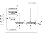
- FIG. 2 is a diagram illustrating a configuration example of the SCM control device 30 according to the present embodiment, and illustrates a configuration of the SCM control device 30 with functional blocks.
- the SCM control device 30 includes a collision detection unit 31, an ambient environment detection unit 33, a subsequent vehicle running state detection unit 35, a subsequent vehicle braking force detection unit 37, an avoidance determination unit 39, a braking force application unit 41, and the like. As the main element. Each of these means is specifically realized by execution of a program by a microcomputer. Further, the SCM control device 30 is provided with a storage means (RAM: Random Access Memory) (not shown), and stores information to be read, calculation results of each means, and the like.
- RAM Random Access Memory
- the collision detection means 31 is configured to be able to detect the collision of the host vehicle 10 based on the sensor value of the acceleration sensor 23 provided in the vehicle 10. For example, when a sudden increase in acceleration in a direction different from the traveling direction of the host vehicle 10 is detected based on the transition of the sensor value of the acceleration sensor 23 stored in the RAM, the collision detection unit 31 determines that the host vehicle 10 Is determined to have collided. In addition to this, for example, when the vehicle 10 is equipped with an airbag device, a collision of the host vehicle 10 may be detected when an airbag deployment instruction signal is detected by the airbag device.
- Ambient environment detection means 33 includes information obtained from vehicle-to-vehicle communication transmitting / receiving antenna 27, ultrasonic sensor, radar device, in-vehicle camera, ITS information transmitting / receiving antenna 29, own vehicle position confirmation sensor 21, etc. Based on this, the surrounding environment of the host vehicle 10 can be detected. For example, based on the infrastructure information obtained by the ITS information transmitting / receiving antenna 29, information such as the presence or absence of obstacles such as guardrails or standing trees, the presence or absence of road shoulders, and the road friction coefficient is detected. In addition, based on the information received by the vehicle-to-vehicle communication antenna 27, information such as the preceding vehicle and the oncoming vehicle is detected.
- the following vehicle running state detection means 35 is configured to be able to detect the presence or absence of the following vehicle and the running state of the following vehicle such as position, vehicle speed, acceleration, weight, yaw rate and the like. Such information can be detected by information received by the vehicle-to-vehicle communication transmitting / receiving antenna 27, an ultrasonic sensor provided in the host vehicle 10, or the like. In addition, not only one succeeding vehicle but also a plurality of succeeding vehicles may be detected.
- the subsequent vehicle braking force detection means 37 is configured to detect whether or not the subsequent vehicle includes a device for automatically controlling the braking force of the host vehicle such as an ABS or a skid prevention device (ESP).
- the SCM control device 30 of the present embodiment is configured such that these pieces of information can be obtained by the vehicle-to-vehicle communication transmitting / receiving antenna 27. In other words, when the following vehicle is equipped with a transmission / reception antenna for inter-vehicle communication, these pieces of information can be detected.
- the avoidance determination unit 39 detects whether or not the subsequent vehicle is based on information detected by the subsequent vehicle running state detection unit 35 and the subsequent vehicle braking force detection unit 37 when the collision detection unit 31 detects a collision of the host vehicle 10. Whether or not the vehicle 10 can be avoided is determined. Whether or not the following vehicle can avoid the own vehicle 10 is based on, for example, the distance between the following vehicle and the own vehicle 10, the speed of the own vehicle 10 and the following vehicle, the mounting status of the braking force control means of the following vehicle, and the like. It is determined by whether there is an inter-vehicle distance at which the following vehicle can stop without colliding with the host vehicle 10.
- the braking force applying means 41 basically controls the wheel cylinders 13FL, 13FR, 13RL of the wheels 11FL, 11FR, 11RL, 11RR of the host vehicle 10 by controlling a valve device or the like provided in the hydraulic circuit 15. Control of hydraulic pressure to 13RR is performed. Specifically, the braking force applying means 41 constituting the SCM control device 30 of the present embodiment controls the valve device of the hydraulic circuit 15 to bring the host vehicle 10 into a full braking state, The brake state of each of the wheels 11FL, 11FR, 11RL, and 11RR is adjusted so that the host vehicle 10 is safely guided in a predetermined direction according to the intervention in the steering operation or the steering operation of the driver. .
- the braking force applying means 41 applies the braking force so that the host vehicle 10 is in a full braking state. Specifically, the supply amount of hydraulic pressure to the wheel cylinders 13FL, 13FR, 13RL, and 13RR of the wheels 11FL, 11FR, 11RL, and 11RR of the host vehicle 10 is increased, and the host vehicle 10 is spun and braked. The brake force of each wheel 11FL, 11FR, 11RL, 11RR is increased to such an extent that it cannot be disabled.
- the braking force applying unit 41 detects the obstacle around the host vehicle 10 detected by the surrounding environment detection unit 33.
- the avoidance space is judged from a position that does not obstruct the traveling direction of the succeeding vehicle as much as possible from the situation of the object, etc.
- a braking force is applied so as to be guided to the space.
- the amount of hydraulic pressure supplied to the wheel cylinders 13FL, 13FR, 13RL, and 13RR is adjusted for each wheel 11FL, 11FR, 11RL, and 11RR of the host vehicle 10 so that the host vehicle 10 moves in a predetermined direction. Adjust the brake force.
- the avoidance space that is a position that does not obstruct the traveling direction of the following vehicle is typically a road shoulder, an oncoming lane when there is no oncoming vehicle, a lane without a following vehicle to travel, etc., but is not limited thereto.
- the braking force applying means 41 of the SCM control device 30 of the present embodiment performs the steering operation on the host vehicle 10. Control is performed preferentially so as to guide the vehicle 10 toward the shoulder according to the intervention or the driver's steering operation.
- FIG. 3 shows an example of the braking force application mode selected by the braking force application means 41 of the SCM control device 30 of the present embodiment.
- the braking force applying means 41 when the own vehicle 10 collides, when the following vehicle can avoid the own vehicle 10 and an obstacle exists in front of the own vehicle 10, the braking force applying means 41 is the vehicle. A braking force is applied so that 10 is in a full braking state. Further, when the own vehicle 10 collides, when the succeeding vehicle can avoid the own vehicle and there is no obstacle ahead of the own vehicle 10, the braking force applying means 41 has an avoidance space such as a road shoulder. If there is no avoidance space, the braking force is applied so that the vehicle 10 gently stops on the travel lane.
- the braking force applying means 41 can avoid the avoidance space such as a road shoulder. If there is, the braking force is applied so that the vehicle 10 is guided to the avoidance space. If there is no avoidance space, the magnitude of the collision energy to the front obstacle and the magnitude of the rear-end collision energy from the following vehicle are taken into consideration. The braking force is applied so that the vehicle 10 is in a full braking state.
- the braking force applying means 41 is provided as an avoidance space such as a road shoulder. If there is, the braking force is applied so that the vehicle 10 is guided to the avoidance space, while if there is no avoidance space, the braking force is not applied to avoid an unexpected situation due to the application of the braking force. .
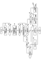
- step S1 the sensor value of the acceleration sensor 23 is read and stored in the RAM.
- step S2 it is determined whether or not the host vehicle 10 has collided from the transition of the sensor value of the acceleration sensor 23 stored in the RAM. If no collision of the host vehicle 10 is detected, the process returns to step S1, while if a collision of the host vehicle 10 is detected, the process proceeds to step S3.
- step S3 information on the surrounding environment of the host vehicle 10 and the following vehicle is detected. Specifically, information received or obtained by a vehicle-to-vehicle communication antenna 27, an ITS information communication antenna 29, an ultrasonic sensor, a radar device, an in-vehicle camera, or the like is detected.
- step S4 it is determined whether there is a following vehicle. If there is a subsequent vehicle, the process proceeds to step S5, whereas if there is no subsequent vehicle, the process proceeds to step S6.
- step S5 which proceeds after it is determined that there is a subsequent vehicle, it is determined whether the subsequent vehicle can avoid the host vehicle 10 or not.
- the SCM control device 30 detects the vehicle speed and acceleration of the host vehicle 10 detected based on the vehicle speed sensor 25 and the acceleration sensor 23, and the following vehicle detected based on inter-vehicle communication, an ultrasonic sensor, and the like.
- step S5 If it is determined in step S5 that there is not enough inter-vehicle distance, the process proceeds to step S11. If it is determined that there is sufficient inter-vehicle distance, the process proceeds to step S6. If it is determined in step S4 that there is no following vehicle or if it is determined in step S5 that there is a sufficient inter-vehicle distance between the host vehicle 10 and the following vehicle, The presence or absence of an obstacle at is determined. Specifically, based on ITS communication, inter-vehicle communication, an ultrasonic sensor, or the like, it is determined whether an obstacle such as a guardrail or a standing tree, a forward vehicle, an oncoming vehicle, or the like exists in front of the host vehicle 10. .
- step S6 If it is determined in step S6 that there is no obstacle ahead of the host vehicle 10, the process proceeds to step S8, whereas if it is determined that an obstacle exists ahead of the host vehicle 10, the process proceeds to step S7.
- step S7 there is a sufficient inter-vehicle distance that allows the following vehicle to stop without colliding with the host vehicle 10, while there is an obstacle ahead. Therefore, the hydraulic pressure is set so that the host vehicle 10 is in a full braking state.
- the valve device or the like of the circuit 15 is controlled to apply a braking force, and the control ends. As a result, the host vehicle 10 quickly stops and secondary collision is avoided.
- step S8 where it is determined that there is no obstacle ahead, it is detected whether there is an avoidance space such as a lane or a shoulder on which the following vehicle or oncoming vehicle is not traveling.
- an avoidance space such as a lane or a shoulder on which the following vehicle or oncoming vehicle is not traveling.
- the process proceeds to step S9, and the host vehicle 10 moves according to the intervention to the steering operation of the host vehicle 10 or the steering operation of the driver.
- the valve device or the like of the hydraulic circuit 15 is controlled so as to be guided in the direction of the avoidance space, the braking force is applied to the host vehicle 10, and the control ends.
- step S10 the process proceeds to step S10, and there is no possibility that the following vehicle will collide with the own vehicle 10. Therefore, the valve device of the hydraulic circuit 15 or the like so that the own vehicle 10 gently stops on the traveling lane. Is controlled and a braking force is applied to complete the control. As a result, the host vehicle 10 is guided to a safe space as much as possible and stopped, and a secondary collision is avoided.
- step S11 which is determined that there is not a sufficient inter-vehicle distance at which the succeeding vehicle can stop without colliding with the own vehicle 10 in step S5 described above, the own vehicle which does not obstruct the progress of the succeeding vehicle as much as possible.
- the presence or absence of ten avoidance spaces is detected. Specifically, based on ITS communication, vehicle-to-vehicle communication, ultrasonic sensors, etc., the presence or absence of a road shoulder adjacent to the roadway or the presence or absence of an oncoming vehicle in the oncoming lane is detected. Presence or absence is detected. If there is an avoidance space such as a shoulder adjacent to the road, the space is preferentially selected.
- step S11 When the avoidance space of the host vehicle 10 is detected in step S11, the process proceeds to step S9 in order to avoid a rear-end collision from the following vehicle, and the host vehicle 10 is operated according to the intervention in the steering operation of the host vehicle 10 or the driver's steering operation.
- the valve device or the like of the hydraulic circuit 15 is controlled so that 10 is guided in the direction of the avoidance space, the braking force is applied to the host vehicle 10, and the control ends.
- the secondary collision of the host vehicle 10 is avoided while avoiding a rear-end collision from the following vehicle.
- step S12 the process proceeds to step S12, and the presence or absence of an obstacle ahead of the host vehicle 10 is determined by the same method as in step S6. If there is an obstacle in front of the host vehicle 10, the process proceeds to step S7 in view of the magnitude of the collision energy to the front obstacle and the magnitude of the rear-end collision energy from the following vehicle.
- the valve device and the like of the hydraulic circuit 15 are controlled so that the braking force is applied and the control is finished. If there is no obstacle ahead of the host vehicle 10, the process proceeds to step S ⁇ b> 13, and braking force applying means is used to avoid an unexpected situation of the host vehicle 10 due to the braking force applied to the host vehicle 10 by the SCM control device 30. It is selected not to intervene by 41, and the control is terminated as it is.
- the host vehicle 10 can be quickly moved in a situation where the following vehicle can avoid the host vehicle 10 when the host vehicle 10 collides. While the vehicle can be safely stopped, the host vehicle 10 is guided to a position as safe as possible in a situation where the following vehicle is difficult to avoid the host vehicle 10. As a result, secondary collisions such as a rear-end collision from the following vehicle and a collision with an obstacle ahead are reduced during the primary collision of the host vehicle 10.
- the control flow described above is an example of a specific flow for carrying out the present invention, and can be changed as appropriate.
- the order of performing the step of determining whether or not the following vehicle can avoid the own vehicle, the presence or absence of an obstacle ahead of the own vehicle, and the presence or absence of an avoidance space may be changed.
- the SCM control device when the possibility of rear-end collision from the following vehicle is low, depending on whether to give priority to guidance to the avoidance space or to stop on the driving lane
- the selected braking force application mode may be different. For example, when the following vehicle can avoid the host vehicle 10, the host vehicle 10 may be in a full braking state regardless of the presence or absence of an obstacle ahead.
Landscapes
- Engineering & Computer Science (AREA)
- Transportation (AREA)
- Mechanical Engineering (AREA)
- Physics & Mathematics (AREA)
- General Physics & Mathematics (AREA)
- Regulating Braking Force (AREA)
Abstract
Description
図1は、本発明の実施の形態にかかる車両用制動制御装置30が搭載された車両10の構成例を示している。
この車両10は、油圧回路15によって各車輪11FL、11FR、11RL、11RRのホイールシリンダ13FL、13FR、13RL、13RRへの作動油圧を制御することで、各車輪11FL、11FR、11RL、11RRの制動力が制御されるようになっている。油圧回路15は公知のブレーキ圧制御装置を構成する油圧回路であって、特にその構成は制限されるものではない。ホイールシリンダ13FL、13FR、13RL、13RRへの作動油圧は、例えば、運転者によるブレーキペダル14の踏み込みにより駆動されるマスタシリンダ17内の圧力に応じて制御される。
図2は、本実施形態のSCM制御装置30の一構成例を示す図であり、SCM制御装置30の構成を機能的なブロックで示している。このSCM制御装置30は、衝突検出手段31と、周囲環境検出手段33と、後続車両走行状態検出手段35と、後続車両制動力検出手段37と、回避判定手段39と、制動力付与手段41等を主たる要素として備えている。これらの各手段は、具体的にはマイクロコンピュータによるプログラムの実行によって実現される。また、SCM制御装置30には、図示しない記憶手段(RAM:Random Access Memory)が備えられ、読み込まれる情報や各手段での演算結果等が記憶される。
図3に示す例では、自車両10の衝突時において、後続車両が自車両10を回避可能であり、かつ、自車両10の前方に障害物が存在する場合に、制動力付与手段41は車両10がフルブレーキング状態となるように制動力を付与する。また、自車両10の衝突時において、後続車両が自車両を回避可能であり、かつ、自車両10の前方に障害物が存在しない場合に、制動力付与手段41は、路肩等の回避スペースがあれば車両10が回避スペースに誘導されるように制動力を付与する一方、回避スペースがなければ車両10が走行車線上で緩やかに停止するよう制動力を付与する。
次に、本実施形態のSCM制御装置30によって行われる、自車両10の衝突時の制御フローについて、図3のフローに基づいて詳細に説明する。
まず、ステップS1において、加速度センサ23のセンサ値が読み込まれ、RAMに記憶される。次いで、ステップS2において、RAMに記憶された加速度センサ23のセンサ値の推移から、自車両10が衝突したか否かが判定される。自車両10の衝突が検知されなければステップS1に戻る一方、自車両10の衝突が検知された時にステップS3に進む。
ステップS4で後続車両が存在しないと判定された場合やステップS5で自車両10と後続車両との間に十分な車間距離があると判定された場合に進んだステップS6では、自車両10の前方での障害物の有無が判定される。具体的には、ITS通信や車車間通信、超音波センサ等に基づき、自車両10の前方に、ガードレールや立木等の障害物、前方車両、対向車両等が存在するか否かが判定される。
また、SCM制御装置で制御を行う前提として、後続車両からの追突の可能性が低い場合に、回避スペースへの誘導を優先的に考えるか、走行車線上での停止を優先的に考えるかによって、選択される制動力付与モードが異なることもあり得る。例えば、後続車両が自車両10を回避可能な場合には、前方の障害物の有無にかかわらず自車両10をフルブレーキング状態にしてもよい。
Claims (7)
- 自車両の衝突を検出する衝突検出手段と、前記自車両の衝突が検出されたときに前記自車両に制動力を付与する制動力付与手段と、を備えた車両用制動制御装置において、
後続車両の有無及び走行状態を検出する後続車両走行状態検出手段と、
前記後続車両における制動制御装置の搭載の有無を検出する後続車両制動力検出手段と、
前記自車両の衝突時に前記後続車両が有る場合において、前記後続車両走行状態検出手段及び前記後続車両制動力検出手段によって検出される情報に基づき、前記後続車両が前記自車両を回避可能か否かを判別する回避判定手段と、を備え、
前記制動力付与手段は、前記回避判定手段による判定結果に基づき前記自車両に付与する制動力を異ならせることを特徴とする車両用制動制御装置。 - 前記後続車両が前記自車両を回避可能と判別されない場合において、前記制動力付与手段は前記後続車両の進行方向を妨げない位置に前記自車両を導くよう前記制動力を付与することを特徴とする請求項1に記載の車両用制動制御装置。
- 前記自車両の衝突時に前記自車両の進行方向における路肩の有無を検出する路肩情報検出手段をさらに備え、
前記後続車両が前記自車両を回避可能と判別されない場合において、前記路肩が検出されたときには、前記制動力付与手段は前記路肩方向に前記自車両を導くよう前記制動力を付与することを特徴とする請求項1又は2に記載の車両用制動制御装置。 - 前記自車両の衝突時に前記自車両の進行方向の障害物の有無を検出する障害物検出手段をさらに備え、
前記後続車両が前記自車両を回避可能と判別された場合において、前記自車両の前方に障害物が検出されたときには、前記制動力付与手段は前記自車両を速やかに停止させるよう前記制動力を付与することを特徴とする請求項1~3のいずれか一項に記載の車両用制動制御装置。 - 前記後続車両が前記自車両を回避可能と判別された場合において、前記自車両の前方に障害物が検出されず、かつ、前記路肩が検出されたときには、前記制動力付与手段は前記自車両を前記路肩方向に導くよう前記制動力を付与することを特徴とする請求項4に記載の車両用制動制御装置。
- 前記後続車両が前記自車両を回避可能と判別された場合において、前記制動力付与手段は前記自車両を速やかに停止させるように前記制動力を付与することを特徴とする請求項1~3のいずれか一項に記載の車両用制動制御装置。
- 前記回避判定手段は、前記制動力付与手段によって前記自車両を速やかに停止させたときに前記後続車両が前記自車両に衝突することなく停止可能な車間距離の有無を検出することを特徴とする請求項1~6のいずれか一項に記載の車両用制動制御装置。
Priority Applications (3)
| Application Number | Priority Date | Filing Date | Title |
|---|---|---|---|
| EP10789275A EP2444290A4 (en) | 2009-06-19 | 2010-02-19 | VEHICLE BRAKE CONTROL DEVICE |
| JP2010519299A JP4550168B1 (ja) | 2009-06-19 | 2010-02-19 | 車両用制動制御装置 |
| US13/376,952 US20120083983A1 (en) | 2009-06-19 | 2010-02-19 | Vehicular braking control device |
Applications Claiming Priority (2)
| Application Number | Priority Date | Filing Date | Title |
|---|---|---|---|
| JP2009146274 | 2009-06-19 | ||
| JP2009-146274 | 2009-06-19 |
Publications (1)
| Publication Number | Publication Date |
|---|---|
| WO2010146897A1 true WO2010146897A1 (ja) | 2010-12-23 |
Family
ID=43356227
Family Applications (1)
| Application Number | Title | Priority Date | Filing Date |
|---|---|---|---|
| PCT/JP2010/052537 Ceased WO2010146897A1 (ja) | 2009-06-19 | 2010-02-19 | 車両用制動制御装置 |
Country Status (4)
| Country | Link |
|---|---|
| US (1) | US20120083983A1 (ja) |
| EP (1) | EP2444290A4 (ja) |
| JP (1) | JP4550168B1 (ja) |
| WO (1) | WO2010146897A1 (ja) |
Cited By (1)
| Publication number | Priority date | Publication date | Assignee | Title |
|---|---|---|---|---|
| JP2016215938A (ja) * | 2015-05-25 | 2016-12-22 | 株式会社ジェイテクト | 車両用操舵装置 |
Families Citing this family (17)
| Publication number | Priority date | Publication date | Assignee | Title |
|---|---|---|---|---|
| DE102010017659A1 (de) * | 2010-06-30 | 2012-01-05 | Ford Global Technologies, Llc | Verfahren und Vorrichtung zur Bereitstellung von Bremsunterstützung in einem Kraftfahrzeug nach einer Erstkollision |
| DE102012203733B3 (de) | 2012-03-09 | 2013-12-19 | Ford Global Technologies, Llc | Verfahren und Vorrichtung zum autonomen Bremsen eines Kraftfahrzeugs nach einer Erstkollision |
| KR101956386B1 (ko) * | 2012-12-26 | 2019-03-08 | 현대자동차주식회사 | 개선된 충돌 확률 산정 방법을 이용한 후방 충돌 경보 시스템 |
| KR101480610B1 (ko) * | 2013-05-21 | 2015-01-08 | 현대자동차주식회사 | 차량의 충돌 방지 장치 및 그 방법 |
| KR101519287B1 (ko) * | 2014-02-14 | 2015-05-11 | 현대자동차주식회사 | 차량 충돌 방지 장치 및 그 방법 |
| JP6036724B2 (ja) * | 2014-02-17 | 2016-11-30 | トヨタ自動車株式会社 | 車両周辺状況認識装置および車両制御装置 |
| US9637096B2 (en) * | 2014-06-16 | 2017-05-02 | Honda Motor Co., Ltd. | Vehicle control apparatus |
| KR102374735B1 (ko) * | 2015-09-14 | 2022-03-15 | 주식회사 만도모빌리티솔루션즈 | 운전지원장치 및 운전지원방법 |
| US10137871B2 (en) | 2016-10-27 | 2018-11-27 | Bendix Commercial Vehicle Systems Llc | Adaptive braking for a vehicle control system |
| KR102463694B1 (ko) * | 2016-12-09 | 2022-11-07 | 현대자동차주식회사 | 인휠 시스템을 이용한 차량의 주행 제어 방법 |
| CN107914686B (zh) * | 2017-11-17 | 2019-06-25 | 吉林大学 | 一种车辆紧急制动装置及方法 |
| KR102463717B1 (ko) * | 2017-12-12 | 2022-11-07 | 현대자동차주식회사 | 군집 차량 제동력 제어 장치, 그를 포함한 시스템 및 그 방법 |
| KR102553730B1 (ko) * | 2018-03-08 | 2023-07-11 | 주식회사 에이치엘클레무브 | 차량의 충돌 회피 제어 장치 및 방법 |
| US10960880B2 (en) * | 2018-03-28 | 2021-03-30 | Intel Corporation | Vehicle slack distribution |
| JP7449811B2 (ja) * | 2020-07-31 | 2024-03-14 | 株式会社Subaru | 車両の緊急連絡装置 |
| JP7484788B2 (ja) * | 2021-03-29 | 2024-05-16 | 株式会社アドヴィックス | 車両の制動制御装置 |
| JP7845158B2 (ja) * | 2022-11-30 | 2026-04-14 | トヨタ自動車株式会社 | 走行支援方法、走行支援装置及び走行支援プログラム |
Citations (7)
| Publication number | Priority date | Publication date | Assignee | Title |
|---|---|---|---|---|
| JPH10211886A (ja) * | 1997-01-29 | 1998-08-11 | Honda Motor Co Ltd | 車両の操舵装置 |
| JP2000313323A (ja) | 1999-05-06 | 2000-11-14 | Toyota Motor Corp | 車輌の制動制御装置 |
| JP2002316629A (ja) * | 2001-04-24 | 2002-10-29 | Toyota Motor Corp | 車両の衝突時制御装置 |
| JP2003081074A (ja) * | 2001-09-13 | 2003-03-19 | Hitachi Ltd | 自動車用ブレーキの制御方法及びその装置 |
| JP2007516127A (ja) * | 2003-11-14 | 2007-06-21 | コンティネンタル・テーベス・アクチエンゲゼルシヤフト・ウント・コンパニー・オッフェネ・ハンデルスゲゼルシヤフト | 事故による損傷を低減する方法及び装置 |
| JP2007230500A (ja) | 2006-03-03 | 2007-09-13 | Mazda Motor Corp | 車両用自動ブレーキ制御装置 |
| JP2008260337A (ja) * | 2007-04-10 | 2008-10-30 | Denso Corp | 走行支援装置 |
Family Cites Families (47)
| Publication number | Priority date | Publication date | Assignee | Title |
|---|---|---|---|---|
| DE2114621C3 (de) * | 1971-03-26 | 1979-06-21 | Messerschmitt-Boelkow-Blohm Gmbh, 8000 Muenchen | Verfahren zur selbsttätigen, abstandgesicherten Brems- und Fahrsteuerung von auf derselben Bahn oder Spur befindlichen Fahrzeugen |
| US4079802A (en) * | 1971-11-11 | 1978-03-21 | Aisin Seiki Company, Limited | Methods and devices for controlling distance between vehicles |
| US4934477A (en) * | 1988-08-18 | 1990-06-19 | Dai Yeu J | Automatic control device for preventing rear-end collision of motorized vehicles |
| US5424726A (en) * | 1992-09-30 | 1995-06-13 | Intrass Company | Method, apparatus and system for transmitting and receiving data in a moving linear chain |
| US5983161A (en) * | 1993-08-11 | 1999-11-09 | Lemelson; Jerome H. | GPS vehicle collision avoidance warning and control system and method |
| US5572449A (en) * | 1994-05-19 | 1996-11-05 | Vi&T Group, Inc. | Automatic vehicle following system |
| US7359782B2 (en) * | 1994-05-23 | 2008-04-15 | Automotive Technologies International, Inc. | Vehicular impact reactive system and method |
| US7426437B2 (en) * | 1997-10-22 | 2008-09-16 | Intelligent Technologies International, Inc. | Accident avoidance systems and methods |
| US6405132B1 (en) * | 1997-10-22 | 2002-06-11 | Intelligent Technologies International, Inc. | Accident avoidance system |
| US6720920B2 (en) * | 1997-10-22 | 2004-04-13 | Intelligent Technologies International Inc. | Method and arrangement for communicating between vehicles |
| US6768944B2 (en) * | 2002-04-09 | 2004-07-27 | Intelligent Technologies International, Inc. | Method and system for controlling a vehicle |
| US5642869A (en) * | 1995-12-01 | 1997-07-01 | Teleengineering, Inc. | Apparatus for detecting the distance between two objects |
| JP3143063B2 (ja) * | 1996-06-07 | 2001-03-07 | 株式会社日立製作所 | 移動体の走行制御装置 |
| JP3732292B2 (ja) * | 1996-11-27 | 2006-01-05 | 本田技研工業株式会社 | 車群走行制御システム |
| US8255144B2 (en) * | 1997-10-22 | 2012-08-28 | Intelligent Technologies International, Inc. | Intra-vehicle information conveyance system and method |
| US7647180B2 (en) * | 1997-10-22 | 2010-01-12 | Intelligent Technologies International, Inc. | Vehicular intersection management techniques |
| US6223125B1 (en) * | 1999-02-05 | 2001-04-24 | Brett O. Hall | Collision avoidance system |
| JP2000322696A (ja) * | 1999-05-07 | 2000-11-24 | Honda Motor Co Ltd | 隊列走行制御装置 |
| DE10024739A1 (de) * | 1999-05-21 | 2000-12-07 | Honda Motor Co Ltd | Kolonnenfahr-Steuervorrichtung |
| DE19944556B4 (de) * | 1999-09-17 | 2008-11-06 | Robert Bosch Gmbh | Verfahren und Vorrichtung zur Steuerung einer Bremsanlage |
| US6765495B1 (en) * | 2000-06-07 | 2004-07-20 | Hrl Laboratories, Llc | Inter vehicle communication system |
| US7365769B1 (en) * | 2000-07-06 | 2008-04-29 | Donald Mager | Activating a vehicle's own brake lights and/or brakes when brake lights are sensed in front of the vehicle, including responsively to the proximity of, and/or rate of closure with, a forward vehicle |
| NL1016371C2 (nl) * | 2000-10-10 | 2002-04-11 | Tno | Signaleringsinrichting voor een motorvoertuig. |
| JP2004013401A (ja) * | 2002-06-05 | 2004-01-15 | Sony Corp | 車両用通信システム、車両、および車両用通信装置 |
| US7124027B1 (en) * | 2002-07-11 | 2006-10-17 | Yazaki North America, Inc. | Vehicular collision avoidance system |
| JP3870924B2 (ja) * | 2003-04-04 | 2007-01-24 | 日産自動車株式会社 | 情報提供装置、情報提供システムおよび情報提供用プログラム |
| JP2004348430A (ja) * | 2003-05-22 | 2004-12-09 | Pioneer Electronic Corp | 急ブレーキ車両警告装置、急ブレーキ情報送信装置、サーバ装置、急ブレーキ警告システム及び方法等 |
| US7321825B2 (en) * | 2003-10-24 | 2008-01-22 | Ford Global Technologies, Llc | Method and apparatus for determining vehicle operating conditions and providing a warning or intervention in response to the conditions |
| US8903617B2 (en) * | 2004-10-05 | 2014-12-02 | Vision Works Ip Corporation | Absolute acceleration sensor for use within moving vehicles |
| US7242287B1 (en) * | 2004-10-19 | 2007-07-10 | Joseph Giovinazzo | Vehicle warning system and method |
| DE102005025510B4 (de) * | 2005-06-03 | 2008-07-03 | Fendt, Günter | Vorrichtung und Verfahren zur Ansteuerung einer Fahrzeugbremsanlage im Rahmen einer Bremsassistenzfunktion |
| DE102005027845B4 (de) * | 2005-06-16 | 2026-01-15 | Robert Bosch Gmbh | Verfahren zur Steuerung der Bremsanlage eines stehenden oder beinahe stehenden Fahrzeugs |
| US7388477B1 (en) * | 2005-09-30 | 2008-06-17 | Neway Systems & Products, Inc. | Chain collision prevention |
| US7523000B2 (en) * | 2005-10-11 | 2009-04-21 | Nissan Technical Center North America, Inc. | Vehicle pre-collision countermeasure system |
| US7495550B2 (en) * | 2005-12-28 | 2009-02-24 | Palo Alto Research Center Incorporated | Method and apparatus for rear-end collision warning and accident mitigation |
| US20070296564A1 (en) * | 2006-06-27 | 2007-12-27 | Howell Mark N | Rear collision warning system |
| US8483903B2 (en) * | 2006-09-07 | 2013-07-09 | Nissan North America, Inc. | Vehicle on-board unit |
| CN101617350A (zh) * | 2007-02-26 | 2009-12-30 | 丰田自动车株式会社 | 用于表明速度和减速度的车车间通信系统及方法 |
| DE102007019991A1 (de) * | 2007-04-27 | 2008-10-30 | Robert Bosch Gmbh | Vermeidung eines Auffahrunfalls bei einem automatischen Bremseingriff eines Fahrzeugsicherheitssystems |
| US20090091440A1 (en) * | 2007-10-09 | 2009-04-09 | Roman Kendyl A | Brake light with pre-brake warning |
| JP5073548B2 (ja) * | 2008-03-27 | 2012-11-14 | 富士重工業株式会社 | 車両用環境認識装置および先行車追従制御システム |
| DE112009001028B4 (de) * | 2008-04-30 | 2017-05-04 | Mitsubishi Electric Corp. | Verfahren zur Bordkommunikation, Bordkommunikationsvorrichtung und Kooperatives Strasse-Fahrzeug/Auto-Auto Kommunikationssystem |
| US8352112B2 (en) * | 2009-04-06 | 2013-01-08 | GM Global Technology Operations LLC | Autonomous vehicle management |
| JP5088349B2 (ja) * | 2009-06-01 | 2012-12-05 | トヨタ自動車株式会社 | 車両走行制御装置 |
| DE102009049368A1 (de) * | 2009-10-14 | 2011-04-21 | GM Global Technology Operations, Inc., Detroit | Verfahren und Vorrichtung zur Vermeidung einer möglichen Kollision eines Objekts mit einer ersten Fahrzeugtüre eines stillstehenden Fahrzeugs |
| US9963127B2 (en) * | 2010-01-15 | 2018-05-08 | Volvo Car Corporation | Collision mitigation system and method for braking a vehicle |
| EP2423063B1 (en) * | 2010-08-23 | 2013-03-06 | Harman Becker Automotive Systems GmbH | Method of detecting the braking of a vehicle |
-
2010
- 2010-02-19 WO PCT/JP2010/052537 patent/WO2010146897A1/ja not_active Ceased
- 2010-02-19 US US13/376,952 patent/US20120083983A1/en not_active Abandoned
- 2010-02-19 JP JP2010519299A patent/JP4550168B1/ja not_active Expired - Fee Related
- 2010-02-19 EP EP10789275A patent/EP2444290A4/en not_active Withdrawn
Patent Citations (7)
| Publication number | Priority date | Publication date | Assignee | Title |
|---|---|---|---|---|
| JPH10211886A (ja) * | 1997-01-29 | 1998-08-11 | Honda Motor Co Ltd | 車両の操舵装置 |
| JP2000313323A (ja) | 1999-05-06 | 2000-11-14 | Toyota Motor Corp | 車輌の制動制御装置 |
| JP2002316629A (ja) * | 2001-04-24 | 2002-10-29 | Toyota Motor Corp | 車両の衝突時制御装置 |
| JP2003081074A (ja) * | 2001-09-13 | 2003-03-19 | Hitachi Ltd | 自動車用ブレーキの制御方法及びその装置 |
| JP2007516127A (ja) * | 2003-11-14 | 2007-06-21 | コンティネンタル・テーベス・アクチエンゲゼルシヤフト・ウント・コンパニー・オッフェネ・ハンデルスゲゼルシヤフト | 事故による損傷を低減する方法及び装置 |
| JP2007230500A (ja) | 2006-03-03 | 2007-09-13 | Mazda Motor Corp | 車両用自動ブレーキ制御装置 |
| JP2008260337A (ja) * | 2007-04-10 | 2008-10-30 | Denso Corp | 走行支援装置 |
Non-Patent Citations (1)
| Title |
|---|
| See also references of EP2444290A4 |
Cited By (1)
| Publication number | Priority date | Publication date | Assignee | Title |
|---|---|---|---|---|
| JP2016215938A (ja) * | 2015-05-25 | 2016-12-22 | 株式会社ジェイテクト | 車両用操舵装置 |
Also Published As
| Publication number | Publication date |
|---|---|
| US20120083983A1 (en) | 2012-04-05 |
| JPWO2010146897A1 (ja) | 2012-12-06 |
| EP2444290A4 (en) | 2012-12-12 |
| EP2444290A1 (en) | 2012-04-25 |
| JP4550168B1 (ja) | 2010-09-22 |
Similar Documents
| Publication | Publication Date | Title |
|---|---|---|
| JP4550168B1 (ja) | 車両用制動制御装置 | |
| US10246090B2 (en) | Vehicle collision severity mitigation | |
| CN106157696B (zh) | 基于车-车通信的自车主动避让系统和避让方法 | |
| KR101864938B1 (ko) | 충돌 회피 지원 장치 | |
| JP6294247B2 (ja) | 車両走行制御装置 | |
| KR102012171B1 (ko) | 지능형 차량 위치 설정에 의한 충격 완화 방법 및 시스템 | |
| EP2763118B1 (en) | Driving support system for a vehicle | |
| JP6470039B2 (ja) | 車両制御システム | |
| KR101775856B1 (ko) | 차량 제어 시스템 및 차량 제어 방법 | |
| US7418345B2 (en) | Method and device for reducing damage caused by an accident | |
| CN104670227B (zh) | 车辆行为控制装置和车辆行为控制系统 | |
| CN107226089A (zh) | 一种无人驾驶汽车避撞策略 | |
| MX2014008539A (es) | Asistencia de trayectoria post-impacto para vehiculos. | |
| CN116137848B (zh) | 用于处理涉及车辆和/或第三方的情况的方法以及系统 | |
| US20200023901A1 (en) | Method and system for providing a steering guidance to a driver of a host vehicle | |
| JP2006188129A (ja) | 衝突負荷低減車両システム | |
| CN107933475A (zh) | 一种减少碰撞损伤的汽车防碰撞系统 | |
| CN115230685A (zh) | 一种车辆碰撞保护控制方法及高级驾驶辅助系统 | |
| JP6805767B2 (ja) | 車両制御システム | |
| JP2007200052A (ja) | 交差点における運転支援装置および交差点における運転支援方法 | |
| JP3451321B2 (ja) | 車の衝突防止制御方法 | |
| KR101113527B1 (ko) | 제동력을 향상 시키기 위한 방법 및 장치 | |
| KR102836350B1 (ko) | 차량 및 그 제어방법 | |
| CN116164986B (zh) | 一种车辆线控制动控制方法及其测试平台 | |
| KR20170070382A (ko) | 2차 사고 방지를 위한 긴급제동 장치 및 방법 |
Legal Events
| Date | Code | Title | Description |
|---|---|---|---|
| ENP | Entry into the national phase |
Ref document number: 2010519299 Country of ref document: JP Kind code of ref document: A |
|
| 121 | Ep: the epo has been informed by wipo that ep was designated in this application |
Ref document number: 10789275 Country of ref document: EP Kind code of ref document: A1 |
|
| WWE | Wipo information: entry into national phase |
Ref document number: 2010789275 Country of ref document: EP |
|
| WWE | Wipo information: entry into national phase |
Ref document number: 13376952 Country of ref document: US |
|
| NENP | Non-entry into the national phase |
Ref country code: DE |