WO2010146906A1 - 光波距離計 - Google Patents
光波距離計 Download PDFInfo
- Publication number
- WO2010146906A1 WO2010146906A1 PCT/JP2010/054586 JP2010054586W WO2010146906A1 WO 2010146906 A1 WO2010146906 A1 WO 2010146906A1 JP 2010054586 W JP2010054586 W JP 2010054586W WO 2010146906 A1 WO2010146906 A1 WO 2010146906A1
- Authority
- WO
- WIPO (PCT)
- Prior art keywords
- light
- frequency
- receiving element
- light receiving
- emitting element
- Prior art date
- Legal status (The legal status is an assumption and is not a legal conclusion. Google has not performed a legal analysis and makes no representation as to the accuracy of the status listed.)
- Ceased
Links
Images




Classifications
-
- G—PHYSICS
- G01—MEASURING; TESTING
- G01S—RADIO DIRECTION-FINDING; RADIO NAVIGATION; DETERMINING DISTANCE OR VELOCITY BY USE OF RADIO WAVES; LOCATING OR PRESENCE-DETECTING BY USE OF THE REFLECTION OR RERADIATION OF RADIO WAVES; ANALOGOUS ARRANGEMENTS USING OTHER WAVES
- G01S17/00—Systems using the reflection or reradiation of electromagnetic waves other than radio waves, e.g. lidar systems
- G01S17/02—Systems using the reflection of electromagnetic waves other than radio waves
- G01S17/06—Systems determining position data of a target
- G01S17/08—Systems determining position data of a target for measuring distance only
- G01S17/32—Systems determining position data of a target for measuring distance only using transmission of continuous waves, whether amplitude-, frequency-, or phase-modulated, or unmodulated
- G01S17/36—Systems determining position data of a target for measuring distance only using transmission of continuous waves, whether amplitude-, frequency-, or phase-modulated, or unmodulated with phase comparison between the received signal and the contemporaneously transmitted signal
Definitions
- the present invention relates to a light wave distance meter, and more particularly, to a light wave distance meter that omits a shutter for switching light emitted from a light emitting element to a distance measuring light path (external light path) and a reference light path (internal light path).
- the light emitted from the light emitting element moves the shutter to move the distance measuring optical path that reciprocates to the target reflector (target, reflecting sheet, or non-prism object) and the light source immediately goes to the light receiving element.
- the inherent error of the light wave rangefinder was corrected by measuring the distance by alternately switching to the reference optical path.
- it involves the movement of the shutter it takes time to measure the distance and also has the disadvantages that the movement becomes slow at low temperatures. Therefore, there has been a demand for a lightwave distance meter that does not use a shutter that switches between a distance measuring optical path and a reference optical path.
- FIG. 9 shows a block diagram of this light wave distance meter.
- This lightwave distance meter includes two light emitting elements 1P and 2P.
- the light 30P emitted from the light emitting element 1P is divided into two by the beam splitter 3P, one of which enters the light receiving element 5P through the distance measuring optical path that reciprocates to the target reflector 60P as the distance measuring light 32P, and the other. Then, it enters the light receiving element 4P as the reference light 33P through the reference optical path inside the optical distance meter.
- the light 31P emitted from the light emitting element 2P becomes reference light and is divided into two by the beam splitter 6P.
- One 34P enters the light receiving element 4P and the other 35P enters the light receiving element 5P.
- a diffuser 51P that diffuses light is disposed in front of the light receiving element 4P, and a scatter 11P that scatters light is disposed in front of the light receiving element 5P.
- Emitting element 1P which is connected to the synthesizer 21P via an amplifier 23P, it emits light that is modulated at a frequency f 1.
- Emitting element 2P which is connected to the synthesizer 22P via an amplifier 24P, it emits light that is modulated at a frequency f 2.
- Both synthesizers 21P and 22P are connected to a common oscillator 20P.
- the light receiving element 4P is connected to the frequency converter 7P via the amplifier 9P, and the light receiving element 5P is connected to the frequency converter 8P via the amplifier 10P.
- Both frequency converters 7P and 8P receive a local oscillation signal having a frequency f LO from a local oscillator 12P.
- Both frequency converters 7P and 8P are converted into intermediate frequency signals f ZF1 and f ZF2 having a frequency equal to the difference between the output signals from the light receiving elements 4P and 5P and the local oscillation signal.
- Filter 13P connected to the frequency converter 7P is adapted pass only the frequency f ZF1 the difference between the frequencies f 1 and f LO, an intermediate frequency signal according to the reference light 33P modulated at a frequency f 1, i.e. reference only the intermediate frequency signal for sorting according to the distance D 1.
- Filter 14P connected to the frequency converter 8P is adapted pass only frequency f ZF2 difference f 2 and f LO, an intermediate frequency signal according to the reference light 35P modulated at a frequency f 2, i.e. reference Only the intermediate frequency signal related to the distance D 2 + D 3 is selected.
- the respective modulation frequencies are changed so that the light modulated at the frequency f 2 is emitted from the light emitting element 1P and the light modulated at the frequency f 1 is emitted from the light emitting element 2P.
- the filter 13P connected to the frequency converter 7P is because so pass only frequency f ZF1 the difference between the frequencies f 1 and f LO, an intermediate frequency according to the reference light 34P modulated at a frequency f 1 signal, i.e. selecting only the intermediate frequency signal according to the reference distance D 2.
- Filter 14P connected to the frequency converter 8P is adapted pass only frequency f ZF2 the difference between the frequencies f 2 and f LO, an intermediate frequency signal according to the distance measuring light 32P modulated at a frequency f 2, that selecting only the intermediate frequency signal according to the measured distance D 0.
- the intermediate frequency signal related to the distance measurement distance D 0 , the reference distances D 1 , D 2 , D 2 + D 3 A total of four intermediate frequency signals are obtained for each of the intermediate frequency signals.
- the filter 13P is connected to the A / D converter 17P through the amplifier 15P.
- the filter 14P is connected to the A / D converter 18P through the amplifier 16P.
- Both A / D converters 17P and 18P are connected to a digital Fourier transformer 19P.
- the present invention has been made in view of the above problems, and an object of the present invention is to provide a lightwave distance meter in which the time required for distance measurement is shortened and the temperature phase drift of electric parts is reduced.
- an optical distance meter includes a first light emitting element that emits light modulated at a plurality of main modulation frequencies (for example, F 1 and F 2 ), A second light emitting element that emits light modulated at a plurality of side modulation frequencies (for example, F 1 - ⁇ f 1 , F 2 - ⁇ f 2 ) close to each of the main modulation frequencies, and light emitted from both light emitting elements
- the first light receiving element and the second light receiving element that receive light, the first frequency converter group connected to the first light receiving element, and the second frequency converter group connected to the second light receiving element
- the light emitted from the first light emitting element is divided into two, one of which enters the first light receiving element through a distance measuring optical path that reciprocates as a distance measuring light to the target reflector, and the other As reference light, it enters the second light receiving element through the first reference light path, and from the second light emitting element.
- the emitted light is divided into two, one of which enters the second light receiving element as the reference light through the second reference light path, and the other enters the first light receiving element as the reference light through the third reference light path.
- the first frequency converter group and the second frequency converter group are each composed of the same number of frequency converters as the main modulation frequency, and each frequency converter has a local oscillation with a different frequency.
- a signal is input, and the frequency of the local oscillation signal is set to frequencies close to both the main modulation frequency and each side modulation frequency close to each main modulation frequency (for example, F 1 + ⁇ f 1 , F 2 + ⁇ f 2).
- the distance to the target reflector is calculated using the intermediate frequency signal generated by each frequency converter.
- each intermediate frequency signal in the lightwave distance meter of the invention according to claim 1, is an integral multiple of the lowest one, and each intermediate frequency signal has a digital bandwidth. It is configured to be separated by a filter.
- the lightwave distance meter of the first aspect of the present invention it is possible to switch between the distance measuring light and the reference light without using a shutter and without changing the modulation frequency. Since the initial phase of the intermediate frequency signal can be obtained at the same time, distance measurement can be performed at a higher speed than in the past. Further, the cost can be reduced by omitting the shutter. Furthermore, according to the present invention, since the distance measurement distance and the reference distance can be measured simultaneously, the temperature phase drift cancels out, and the temperature phase drift of the electrical component can be reduced. For this reason, conventionally, in order to reduce the temperature phase drift of the electrical components, the light emitting element during the continuous distance measurement is kept on. However, in the present invention, the light emitting element is turned on / off for each distance measurement. This makes it possible to save power.
- the frequency of each intermediate frequency signal is an integral multiple of the lowest one, and each of the intermediate frequency signals is separated by the digital bandpass filter.
- the frequency can be reliably separated to increase the measurement accuracy.
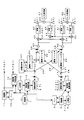
- This light wave distance meter includes two light emitting elements 13 and 14 such as laser diodes, and light modulated by frequencies F 1 and F 2 (hereinafter referred to as main modulation frequency) from the first light emitting element 13.
- the light is emitted and modulated from the second light-emitting element 14 at frequencies F 1 - ⁇ f 1 and F 2 - ⁇ f 2 (hereinafter referred to as side modulation frequencies) close to the main modulation frequencies F 1 and F 2, respectively. Emits light.
- the light emitted from the first light emitting element 13 is divided into two, one of which is incident on the first light receiving element 40 through the distance measuring optical path 23 that reciprocates to the target reflector 22 as distance measuring light, The other enters the second light receiving element 48 through the first reference light path 26 as reference light.
- the light emitted from the second light-emitting element 14 is divided into two parts, one being the reference light and entering the second light-receiving element 48 via the second reference light path 31, and the other being the reference light. The light enters the first light receiving element 40 through the three reference light paths 29.
- the first light receiving element 40 is connected to the first frequency conversion groups 42 and 44, and the second light receiving element 48 is connected to the second frequency conversion groups 50 and 52. That is, the output of the first light-receiving element 40 is the main modulation frequencies F 1 and is divided into two same number as in F 2, one of which is input to the first frequency converter 42 and the other second frequency conversion Is input to the device 44.
- the output of the second light receiving element 48 is also divided into two, which is the same as the number of main modulation frequencies F 1 and F 2 , one being input to the third frequency converter 50 and the other being the fourth frequency converter 52. Is input.
- the first frequency converter 42 the main modulation frequencies F 1 to modulated by a signal obtained from the distance measuring light having passed through the distance measuring optical path 23, the main modulation frequencies F 1 and near the aforementioned modulation frequencies F 1 -.DELTA.f 1 Multiplying the local oscillation signal of frequency F 1 + ⁇ f 1 adjacent to each of them generates an intermediate frequency signal of frequency ⁇ f 1 .
- the first frequency converter 42 multiplied by the local oscillation signal beside the modulation frequency F 1 -.DELTA.f 1 frequency modulated by the third reference light path signals obtained 29 from the reference light passing through at F 1 + Delta] f 1
- an intermediate frequency signal having a frequency 2 ⁇ f 1 is generated.
- the second frequency converter 44 the main modulation frequency F is modulated to a signal obtained from the distance measuring light having passed through the distance measuring optical path 23 at 2, the main modulation frequency F 2 and near the aforementioned modulation frequency F 2 -.DELTA.f 2 Multiplying the local oscillation signal of frequency F 2 + ⁇ f 2 adjacent to each of them generates an intermediate frequency signal of frequency ⁇ f 2 .
- the second frequency converter 44 multiplies the local oscillation signal beside the modulation frequency F 2 -.DELTA.f frequency modulated by a signal obtained from the third reference reference light having passed through the optical path 29 at 2 F 2 + Delta] f 2 Then, an intermediate frequency signal having a frequency of 2 ⁇ f 2 is generated.
- the third frequency converter 50 multiplies the signal obtained from the reference light modulated by the main modulation frequency F 1 and passed through the first reference optical path 26 by the local oscillation signal having the frequency F 1 + ⁇ f 1 to obtain the frequency ⁇ f. 1 intermediate frequency signal is generated.
- the third frequency converter 50 multiplied by the local oscillation signal beside the modulation frequency F 1 -.DELTA.f 1 frequency modulated by the second reference light path 31 a signal obtained from the reference light passing through at F 1 + ⁇ f 1
- an intermediate frequency signal having a frequency 2 ⁇ f 1 is generated.
- the fourth frequency converter 52 multiplies the signal obtained from the reference light modulated by the main modulation frequency F 2 and passed through the first reference optical path 26 by the local oscillation signal having the frequency F 2 + ⁇ f 2 to obtain the frequency ⁇ f. 2 intermediate frequency signals are generated.
- the fourth frequency converter 52 multiplies the local oscillation signal beside the modulation frequency F 2 -.DELTA.f 2 frequency modulated by the second reference light path 31 a signal obtained from the reference light passing through in F 2 + Delta] f 2 Then, an intermediate frequency signal having a frequency of 2 ⁇ f 2 is generated.
- the intermediate frequency signal of the frequency Delta] f 1 and Delta] f 2 according to the distance measuring optical path 23, an intermediate frequency signal of frequency Delta] f 1 and Delta] f 2 according to the first reference light path 26, the frequency of the second reference light path 31 2.DELTA.f 1 and intermediate frequency signals 2.DELTA.f 2, 8 two intermediate frequency signals to match the third reference frequency 2.DELTA.f 1 according to the optical path 29 and the intermediate frequency signal 2.DELTA.f 2 is obtained at a time. If the eight intermediate frequency signals are separated by a suitable means such as a filter or a Fourier transformer, and the initial phase of each intermediate frequency signal is obtained, the distance to the target 22 is calculated by correcting the error generated inside the lightwave rangefinder. Is done.
- This lightwave distance meter will be described in more detail based on the block diagram of FIG.
- the signal having the main modulation frequency F 1 is input to the frequency divider 2 and also input to the oscillators 5 and 11 via the PLLs 9 and 10.
- the PLLs 9 and 10 are used to accurately oscillate the oscillators 5 and 11 at the side modulation frequency F 1 ⁇ f 1 and the local oscillation frequency F 1 + ⁇ f 1 .
- Dividing unit 2 a signal of the main modulation frequencies F 1 by dividing, for generating a signal of the main modulation frequency F 2.
- the signals of the main modulation frequencies F 2 and F 1 are input to the drive circuit 4 through the frequency superimposing circuit 3.
- the first light emitting element 13 is driven by the drive circuit 4 and emits light modulated at the main modulation frequencies F 1 and F 2 .
- the oscillator 5 generates a signal having a side modulation frequency F 1 ⁇ f 1 .
- the signal of the side modulation frequency F 1 - ⁇ f 1 is further frequency-divided by the frequency divider 6 to become a signal of the side modulation frequency F 2 - ⁇ f 2 .
- the signals of the side modulation frequencies F 1 - ⁇ f 1 and F 2 - ⁇ f 2 are input to the drive circuit 8 via the frequency superimposing circuit 7.
- the second light emitting element 14 is driven by the drive circuit 8, and emits the modulated light beside the modulation frequency F 1 -.DELTA.f 1 and F 2 -.DELTA.f 2.
- Oscillator 11 generates a local oscillation signal of frequency F 1 + ⁇ f 1. From this local oscillation signal of frequency F 1 + ⁇ f 1, a local oscillation signal of frequency F 2 + ⁇ f 2 is also generated by the frequency generation circuit 12. These local oscillation signals of the frequencies F 1 + ⁇ f 1 and F 2 + ⁇ f 2 are input to the frequency converters 42, 44, 50, and 52, as will be described later.
- the light emitted from the first light emitting element 13 is divided into two by the beam splitter 20, one of which is emitted as distance measuring light from a light transmission optical system (not shown) and travels back and forth to the target reflector 22.
- a density filter 24 for adjusting the amount of light and a light receiving optical system 25 are arranged in front of the light receiving element 40. Also in the first reference optical path 26, a density filter 27 for adjusting the amount of light is disposed in front of the light receiving element 48.
- the light emitted from the second light emitting element 14 is divided into two by the beam splitter 28, one of which enters the second light receiving element 48 via the second reference optical path 31 as the reference light, and the other is the reference.
- the second reference optical path 31 is also provided with a density filter 32 for adjusting the amount of light before the light receiving element 48
- the third reference optical path 29 is also provided with a density filter 30 for adjusting the amount of light before the light receiving element 40. Is arranged.
- the output of the first light receiving element 40 is divided into two through an amplifier 41, one being input to the first frequency converter 42 and the other being input to the second frequency converter 44.
- the output of the second light receiving element 48 is also divided into two through the amplifier 49, one being input to the third frequency converter 50 and the other being input to the fourth frequency converter 52.
- a total of eight intermediate frequency signals can be obtained from the first to fourth frequency converters 42, 44, 50, and 52.
- the intermediate frequency signals output from the frequency converters 42, 44, 50, and 52 are removed of high frequency components by the low-pass filters 43, 45, 51, and 53, respectively.
- the outputs of the low-pass filter 43 and the low-pass filter 45 are added by the adder 46 and then input to the A / D converter 47. That is, the A / D converter 47 includes two intermediate frequency signals of the frequencies ⁇ f 1 and ⁇ f 2 related to the distance measuring optical path 23 and two intermediate frequencies of the frequencies 2 ⁇ f 1 and 2 ⁇ f 2 related to the third reference optical path 29. A signal is input. These intermediate frequency signals are A / D converted and then separated by a digital band filter (not shown), and the initial phase and amplitude of each intermediate frequency signal are obtained.
- the outputs of the low-pass filter 51 and the low-pass filter 53 are added by the adder 54 and then input to the A / D converter 55. That is, the A / D converter 55, the frequency Delta] f 1 according to the first reference light path 26, and two intermediate frequency signals Delta] f 2, the frequency 2.DELTA.f 1 according to the second reference optical path 31, and 2 2.DELTA.f 2 Two intermediate frequency signals are input. These intermediate frequency signals are A / D converted and then separated by a digital band filter (not shown), and the initial phase and amplitude of each intermediate frequency signal are obtained.
- the distance to the target reflector 22 is calculated by correcting an error generated inside the light wave rangefinder. Further, when the amplitudes of the intermediate frequency signals are also obtained, these amplitudes are used for light amount adjustment by the density filters 24, 27, 30, and 32.
- each of the intermediate frequency signals is set to a signal level that is 1 ⁇ 4 that of only one signal when input to the A / D converters 47 and 55. This is to prevent the input level from being saturated when the four signals are combined.
- each intermediate frequency signal level may be set to a signal level equal to or higher than 1 ⁇ 4 when only one signal is used.
- the present embodiment it is possible to switch the distance measuring light and the reference light without using a shutter and without switching the frequency, and the initial phases of the intermediate frequency signals related to the distance measuring light path and the reference light path are simultaneously set. Therefore, distance measurement can be performed faster than before. Further, the cost can be reduced by omitting the shutter. Further, conventionally, in order to reduce the temperature phase drift, the light emitting element during the continuous distance measurement is kept on. However, according to the present embodiment, since the distance measurement optical path and the reference optical path can be measured simultaneously, the temperature phase drift cancels out, so that the power of the light emitting element can be turned on / off for each distance measurement to save power. be able to.
- the local oscillation frequency F lo (1 + a) F 1 applied to the frequency converters 42 and 50 connected to the light receiving elements 40 and 48, and a>0> b.
- Waveform y 1 of the output of the light receiving element 40 is as follows.
- y 1 y pd1, ld1 cos ⁇ 2 ⁇ F 1 t + ⁇ ld1 (F 1) + ⁇ pd1 (F 1) -2 ⁇ F 1 (2D 0 / c) ⁇ + Y pd1, ld2 cos ⁇ 2 ⁇ (1 + b) F 1 t + ⁇ ld2 ((1 + b) F 1 ) + ⁇ pd1 ((1 + b) F 1 ) -2 ⁇ (1 + b) F 1 (2D 3 / c) ⁇ (1)
- Waveform y 2 of the output of the light receiving element 48 is as follows.
- y 2 y pd2, ld1 cos ⁇ 2 ⁇ F 1 t + ⁇ ld1 (F 1) + ⁇ pd2 (F 1) -2 ⁇ F 1 (2D 1 / c) ⁇ + Y pd2, ld2 cos ⁇ 2 ⁇ (1 + b) F 1 t + ⁇ ld2 ((1 + b) F 1 ) + ⁇ pd2 ((1 + b) F 1 ) -2 ⁇ (1 + b) F 1 (2D 2 / c) ⁇ (2)
- each symbol is defined as follows.
- y pd1, ld1 Amplitude of signal between first light emitting element 13 and first light receiving element 40
- y pd1, ld2 Amplitude of signal between second light emitting element 14 and first light receiving element 40
- y pd2, ld1 Amplitude of signal between second light emitting element 14 and first light receiving element 40
- y pd2, ld1 Amplitude y pd2, ld2 of the signal between the first light emitting element 13 and the second light receiving element 48: amplitude ⁇ ld1 of the signal between the second light emitting element 14 and the second light receiving element 48: first light emitting element 13 temperature phase drift [psi ld2: temperature phase drift [psi pd1 of the second light-emitting element 14: first receiving temperature of the element 40 phase drift [psi pd2: temperature phase drift 2D 0 of the second light-receiving element 48: light wave distance meter 2D 1
- the waveform y 3 of the local oscillation signal input to frequency converter 42, 50, when the amplitude of the local oscillation signal y lo, and the initial phase of the local oscillation signal phi, is as follows.
- y 3 y lo cos ⁇ 2 ⁇ (1 + a) F 1 t + ⁇ (3)
- the output waveform from the low pass filter 43 and 51 connected to the frequency converter 42,50 y 4, y 5 is, y 1 ⁇ y 3, y 2 ⁇ y 3 to a temperature phase drift of low pass filter 43 and 51 respectively
- ⁇ f1 and ⁇ f2 the following equation is obtained.
- ⁇ is the initial phase of the intermediate frequency signal (where F is the modulation frequency)
- F is the modulation frequency
- the phase of the first term of y 4 related to the distance measurement optical path 23 The distance value obtained from the component is d 0
- the distance value obtained from the second phase component of y 4 related to the third reference beam 29 is d 3
- the y 5th value related to the first reference beam 26 is If the distance value obtained from the phase component of the first term is d 1 , and the distance value obtained from the phase component of the second term of y 5 related to the second reference beam 31 is d 2 , d 0 , d 3 , d 1, d 2 are respectively obtained as follows.
- F1 75 MHz.
- equation (7) can be written as: (D 0 ⁇ d 3 ) ⁇ (d 1 ⁇ d 2 ) ⁇ 2D 0 ⁇ 2D 1 + 2D 2 ⁇ 2D 3 + [ ⁇ 4 / (2 ⁇ ) ⁇ ⁇ f1 (aF 1 ) ⁇ ⁇ ⁇ 4 / (2 ⁇ (1 + b)) ⁇ ⁇ f1 ((ab) F 1 ) ⁇ ] -[ ⁇ 4 / (2 ⁇ ) ⁇ ⁇ f2 (aF 1 ) ⁇ - ⁇ 4 / (2 ⁇ (1 + b)) ⁇ ⁇ f2 ((ab) F 1 ) ⁇ ] (10)
- a> b> 0, b> 0> a, and 0> b> a may be satisfied in addition to a> 0> b.
- An example of a frequency having such a condition is shown in FIG. When b> a> 0 and 0> a> b, the effect of reducing the temperature phase drift is small.
- the periodic function y multiplied by a sin wave having the same period as the fundamental wave (having the lowest frequency) a 1 sin ⁇ t + b 1 cos ⁇ t is integrated over one period of the fundamental wave.
- Motomari is a 1
- a n is obtained when integrated over one period of the fundamental wave are multiplied by sin wave of n times of a fundamental wave with respect to the periodic function y.
- b 1 is obtained, and the periodic function y is multiplied by n times the fundamental wave.
- the lowest frequency of each intermediate frequency signal is ⁇ f 2 , and the others are 2 ⁇ f 2 , ⁇ f 1 , 2 ⁇ f 1 which are integer multiples of ⁇ f 2 . Therefore, the total intermediate frequency signal obtained by adding the four intermediate frequency signals becomes a periodic function y having the frequency ⁇ f 2 as the fundamental wave a 1 sin ⁇ t + b 1 cos ⁇ t, and can be expressed by the equations (11) to (13).
- the a 1 The total are multiplied by sin wave having the same period as the fundamental wave appropriately times (e.g. 320 times) sampled and the total intermediate frequency signal y obtained by adding the four intermediate frequency signals for one period of the fundamental wave I want.
- the sum of those multiplied by a cos wave having the same period as the fundamental wave of all intermediate frequency signal y as appropriate number of times of sampling for one period of the fundamental wave b 1 is obtained. From this, using the equations (14) and (15), the amplitude A 1 and the initial phase ⁇ 1 of the intermediate frequency signal having the frequency ⁇ f 2 can be obtained.
- the total intermediate frequency signal y when summing multiplied by the sin wave of n times of a fundamental wave by appropriately number of times of sampling for one period of the fundamental wave a n is obtained.
- B n is determined when the sum are multiplied by cos wave of n times of a fundamental wave of all intermediate frequency signal y as appropriate number of times of sampling for one period of the fundamental wave. From this, using the equations (14) and (15), the amplitude An and the initial phase ⁇ n of the intermediate frequency signal which is an n-th harmonic can be obtained.
- the frequency ratio of the intermediate frequency signals is 1: 2: 20: 40
- the amplitudes A 20 and A 40 and the initial phase ⁇ are also obtained for the intermediate frequencies of the frequencies ⁇ f 1 and 2 ⁇ f 1. 20, it is possible to determine the phi 40. In the case of this frequency ratio, it is not necessary to calculate other than A 1 , A 2 , A 20 , A 40 and ⁇ 1 , ⁇ 2 , ⁇ 20 , ⁇ 40 .
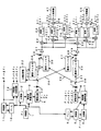
- amplifiers 60, 61, 62, and 63 are arranged after the low-pass filters 43, 45, 51, and 53, respectively, and the signal levels input to the adders 46 and 54 are adjusted. May be.
- branching circuits 70 and 71 are arranged after the amplifiers 41 and 49 so that only appropriate signals are input to the frequency converters 42, 44, 50, and 52, respectively. Also good.
- the output of the amplifier 61 following the low-pass filter 45 is input to the adder 54, and the output of the amplifier 63 following the low-pass filter 53 is input to the adder 46.
- the A / D converters 47 and 55 are supplied with three intermediate frequency signals having a large signal level related to the reference optical path and an intermediate frequency signal having a low signal level related to the distance measuring optical path. Then, as in the embodiment shown in FIGS. 2 to 5, four intermediate frequency signals related to the reference optical path are input to the A / D converter 55, and two intermediate frequency signals related to the reference optical path are input to the A / D converter 47.
- the amplification degree of the amplifiers 62 and 63 can be lowered, and the input signal to the A / D converter 47 can be hardly saturated. On the contrary, since the amplification degree of the amplifiers 60 and 61 can be increased, further long-distance measurement is possible.
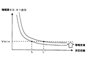
- FIG. 7 shows the relationship between the measurement distance and the outputs of the amplifiers 60 and 61. Since the received light amount of the light receiving elements 40 and 48 becomes smaller as the distance is longer, the outputs of the amplifiers 60 and 61 of the amplifiers 60 and 61 become lower right. When the amplification degree is small, the minimum level Vmin necessary for input to the A / D converters 47 and 55 is higher than the distance L when the distance is short.
- the output of the amplifiers 60 and 61 can be amplified to the minimum level Vmin necessary for input to the A / D converters 47 and 55 even at a far distance L ′. Further distance measurement becomes possible.
- the frequency F 3 is added to the main modulation frequency generated by the frequency divider 2, and the frequency F 3 ⁇ f 3 is added to the side modulation frequency generated by the frequency divider 6.
- the light emitting elements 13 and 14 are modulated at three frequencies, respectively, and two frequency converters 70 and 72 and two low-pass filters 71 and 73 are added.
- the frequency converters 70 and 72 each have a frequency F 3.
- the frequencies ⁇ f 3 and 2 ⁇ f 3 of the intermediate frequency signal are too low to be handled by an amplifier or a filter, the local oscillation frequency is changed to F 3 + ⁇ f 3 + ⁇ f 3 and the frequencies ⁇ f 3 + ⁇ f 3 , ⁇ f An intermediate frequency signal of 3 + 2 ⁇ f 3 may be generated.
- the frequencies of all the intermediate frequency signals need to be integral multiples of the lowest frequency ⁇ f 3 + ⁇ f 3 so that each intermediate frequency signal can be reliably separated by the digital band filter.
- the present invention is not limited to the above-described embodiments.
- the present invention is widely applied not only to the optical distance meter but also to surveying instruments incorporating the optical distance meter, such as a total station and other distance measuring devices. Available.
Landscapes
- Physics & Mathematics (AREA)
- Electromagnetism (AREA)
- Engineering & Computer Science (AREA)
- Computer Networks & Wireless Communication (AREA)
- General Physics & Mathematics (AREA)
- Radar, Positioning & Navigation (AREA)
- Remote Sensing (AREA)
- Optical Radar Systems And Details Thereof (AREA)
- Measurement Of Optical Distance (AREA)
- Instruments For Measurement Of Length By Optical Means (AREA)
Abstract
Description
第1の発光素子13から出射された光は、ビームスプリッタ20で2つに分けられ、一方は図示しない送光光学系から測距光として出射され、目標反射物22までを往復する測距光路23を経て第1の受光素子40に入射し、他方は参照光として、第1の参照光路26を経て第2の受光素子48に入射する。測距光路23には、受光素子40の前に、光量調整用の濃度フィルタ24と受光光学系25が配置されている。第1の参照光路26にも、受光素子48の前に光量調整用の濃度フィルタ27が配置されている。
y1=ypd1,ld1cos{2πF1t+ψld1(F1)+ψpd1(F1)-2πF1(2D0/c)}
+ypd1,ld2cos{2π(1+b)F1t+ψld2((1+b)F1)+ψpd1((1+b)F1)-2π(1+b)F1(2D3/c)} (1)
y2=ypd2,ld1cos{2πF1t+ψld1(F1)+ψpd2(F1)-2πF1(2D1/c)}
+ypd2,ld2cos{2π(1+b)F1t+ψld2((1+b)F1)+ψpd2((1+b)F1)-2π(1+b)F1(2D2/c)} (2)
ypd1,ld1:第1の発光素子13と第1の受光素子40間の信号の振幅
ypd1,ld2:第2の発光素子14と第1の受光素子40間の信号の振幅
ypd2,ld1:第1の発光素子13と第2の受光素子48間の信号の振幅
ypd2,ld2:第2の発光素子14と第2の受光素子48間の信号の振幅
ψld1:第1の発光素子13の温度位相ドリフト
ψld2:第2の発光素子14の温度位相ドリフト
ψpd1:第1の受光素子40の温度位相ドリフト
ψpd2:第2の受光素子48の温度位相ドリフト
2D0:光波距離計から目標反射物までの往復距離
2D1:第1の参照光路26の光路長
2D2:第2の参照光路31の光路長
2D3:第3の参照光路29の光路長
c:光速
y3=ylocos{2π(1+a)F1t+φ} (3)
y4=(ypd1,ld1ylo/2)cos{2πaF1t-ψld1(F1)-ψpd1(F1)+ψf1(aF1)+2πF1(2D0/c)+φ}
+(ypd1,ld2ylo/2)cos{2π(a-b)F1t-ψld2((1+b)F1)-ψpd1((1+b)F1)+ψf1((a-b)F1)+2π(1+b)F1(2D3/c)+φ} (4)
y5=(ypd2,ld1ylo/2)cos{2πaF1t-ψld1(F1)-ψpd2(F1)+ψf2(aF1)+2πF1(2D1/c)+φ}
+(ypd2,ld2ylo/2)cos{2π(a-b)F1t-ψld2((1+b)F1)-ψpd2((1+b)F1)+ψf2((a-b)F1)+2π(1+b)F1(2D2/c)+φ} (5)
d0=2D0+{4/(2π)}{-ψld1(F1)-ψpd1(F1)+ψf1(aF1)+φ}
d3=2D3+{4/(2π(1+b)){-ψld2((1+b)F1)-ψpd1((1+b)F1)+ψf1((a-b)F1)+φ}
d1=2D1+{4/(2π)}{-ψld1(F1)-ψpd2(F1)+ψf2(aF1)+φ}
d2=2D2+{4/(2π(1+b))}{-ψld2((1+b)F1)-ψpd2((1+b)F1)+ψf2((a-b)F1)+φ} (6)
(d0-d3)-(d1-d2)=d0-d1+d2-d3
=2D0-2D1+2D2-2D3
+{4/(2π)}{ψPd2(F1)-ψpd1(F1)-ψf2(aF1)+ψf1(aF1)}
-{4/(2π(1+b))}{ψPd2((1+b)F1)-ψpd1((1+b)F1)-ψf2((a-b)F1)+ψf1((a-b)F1)} (7)
{4/(2π)}{ψPd2(F1)≒{4/(2π(1+b))}{ψPd2((1+b)F1)} (8)
{4/(2π)}{-ψPd1(F1)≒{4/(2π(1+b))}{-ψPd1((1+b)F1)} (9)
(d0-d3)-(d1-d2)≒2D0-2D1+2D2-2D3
+[{4/(2π)}{ψf1(aF1)}-{4/(2π(1+b))}{ψf1((a-b)F1)}]
-[{4/(2π)}{ψf2(aF1)}-{4/(2π(1+b))}{ψf2((a-b)F1)}] (10)
y=a1sinωt+a2sin2ωt+a3sin3ωt+・・・・+ansin(nωt)+・・・・・
+b1cosωt+b2cos2ωt+b3cos3ωt+・・・・bncos(nωt)+・・・・ (11)
bn=(1/π)∫0 2πycos(nωt)dt (13)
An=√(an 2+bn 2) (14)
φn=tan-1(bn/an) (15)
22 目標反射物
23 測距光路
26、29、31 参照光路
40、48 受光素子
42、44、50、52 周波数変換器
F1、F2、F3 主変調周波数
F1-Δf1、F2-Δf2、F3-Δf3 傍変調周波数
F1+Δf1、F2+Δf2、F3+Δf3 局部発振周波数
Claims (2)
- 複数の主変調周波数で変調された光を出射する第1の発光素子と、前記各主変調周波数それぞれに近接した複数の傍変調周波数で変調された光を出射する第2の発光素子と、両発光素子から出射された光を受光する第1の受光素子及び第2の受光素子と、第1の受光素子に接続された第1の周波数変換器群と、第2の受光素子に接続された第2の周波数変換器群とを備え、
第1の発光素子から出射された光は2つに分けられ、一方は測距光として目標反射物までを往復する測距光路を経て第1の受光素子に入射し、他方は参照光として第1の参照光路を経て第2の受光素子に入射し、第2の発光素子から出射された光は2つに分けられ、一方は参照光として第2の参照光路を経て第2の受光素子に入射し、他方は参照光として第3の参照光路を経て第1の受光素子に入射し、
前記第1の周波数変換器群及び前記第2の周波数変換器群は、それぞれ、前記主変調周波数と同数の周波数変換器から構成され、各周波数変換器にはそれぞれ異なる周波数の局部発振信号が入力され、該局部発振信号の周波数は、それぞれ、各主変調周波数と各主変調周波数に近接した各傍変調周波数との両方に近接した周波数とされ、
前記各周波数変換器で発生させた中間周波信号を用いて目標反射物までの距離を算出する光波距離計。 - 前記各中間周波信号の周波数は、最も低いものに対して整数倍になっており、前記各中間周波信号はデジタル帯域フィルタによって分離される請求項1に記載の光波距離計。
Priority Applications (3)
| Application Number | Priority Date | Filing Date | Title |
|---|---|---|---|
| CN2010800103243A CN102341726B (zh) | 2009-06-17 | 2010-03-17 | 光波距离计 |
| US13/258,744 US8570494B2 (en) | 2009-06-17 | 2010-03-17 | Electro-optical distance meter |
| DE112010002587.8T DE112010002587B4 (de) | 2009-06-17 | 2010-03-17 | Elektrooptischer Abstandsmesser |
Applications Claiming Priority (2)
| Application Number | Priority Date | Filing Date | Title |
|---|---|---|---|
| JP2009-144488 | 2009-06-17 | ||
| JP2009144488A JP5014382B2 (ja) | 2009-06-17 | 2009-06-17 | 光波距離計 |
Publications (1)
| Publication Number | Publication Date |
|---|---|
| WO2010146906A1 true WO2010146906A1 (ja) | 2010-12-23 |
Family
ID=43356236
Family Applications (1)
| Application Number | Title | Priority Date | Filing Date |
|---|---|---|---|
| PCT/JP2010/054586 Ceased WO2010146906A1 (ja) | 2009-06-17 | 2010-03-17 | 光波距離計 |
Country Status (5)
| Country | Link |
|---|---|
| US (1) | US8570494B2 (ja) |
| JP (1) | JP5014382B2 (ja) |
| CN (1) | CN102341726B (ja) |
| DE (1) | DE112010002587B4 (ja) |
| WO (1) | WO2010146906A1 (ja) |
Families Citing this family (7)
| Publication number | Priority date | Publication date | Assignee | Title |
|---|---|---|---|---|
| TWI478382B (zh) | 2012-06-26 | 2015-03-21 | Lextar Electronics Corp | 發光二極體及其製造方法 |
| US9484447B2 (en) | 2012-06-29 | 2016-11-01 | Intel Corporation | Integration methods to fabricate internal spacers for nanowire devices |
| RU2610514C2 (ru) * | 2015-02-11 | 2017-02-13 | Открытое Акционерное общество "Ростовский оптико-механический завод" | Лазерный фазовый дальномер |
| JP6991034B2 (ja) * | 2017-10-19 | 2022-01-12 | 株式会社トプコン | 光波距離計及びフィードバック信号の変調周波数決定方法 |
| DE102018125253B3 (de) * | 2018-10-12 | 2019-12-24 | Pepperl+Fuchs Gmbh | Optischer Sensor nach dem Laufzeitprinzip zum Nachweis von Objekten in einem Überwachungsbereich |
| JP2023142442A (ja) * | 2022-03-25 | 2023-10-05 | 株式会社トプコン | 光波距離計 |
| JP2023142441A (ja) * | 2022-03-25 | 2023-10-05 | 株式会社トプコン | 光波距離計 |
Citations (3)
| Publication number | Priority date | Publication date | Assignee | Title |
|---|---|---|---|---|
| JPS5838880A (ja) * | 1981-08-31 | 1983-03-07 | Tokyo Optical Co Ltd | 光波距離計 |
| JPH0666516A (ja) * | 1992-08-21 | 1994-03-08 | Idec Izumi Corp | レーザ干渉測長装置 |
| JP2005221330A (ja) * | 2004-02-04 | 2005-08-18 | Hokuyo Automatic Co | レンジセンサの距離較正方法 |
Family Cites Families (7)
| Publication number | Priority date | Publication date | Assignee | Title |
|---|---|---|---|---|
| US5745437A (en) | 1996-08-05 | 1998-04-28 | Wachter; Eric A. | Method and apparatus for coherent burst ranging |
| DE10006493C2 (de) * | 2000-02-14 | 2002-02-07 | Hilti Ag | Verfahren und Vorrichtung zur optoelektronischen Entfernungsmessung |
| CN1289919C (zh) * | 2000-08-25 | 2006-12-13 | 莱卡地球系统公开股份有限公司 | 测距方法及装置 |
| JP4104991B2 (ja) * | 2003-01-16 | 2008-06-18 | 株式会社トプコン | 光波距離計 |
| JP4707363B2 (ja) | 2004-10-20 | 2011-06-22 | 株式会社 ソキア・トプコン | 光波距離計 |
| JP2007057251A (ja) * | 2005-08-22 | 2007-03-08 | Anritsu Corp | 光干渉計型位相検出装置 |
| JP4855749B2 (ja) * | 2005-09-30 | 2012-01-18 | 株式会社トプコン | 距離測定装置 |
-
2009
- 2009-06-17 JP JP2009144488A patent/JP5014382B2/ja not_active Expired - Fee Related
-
2010
- 2010-03-17 WO PCT/JP2010/054586 patent/WO2010146906A1/ja not_active Ceased
- 2010-03-17 DE DE112010002587.8T patent/DE112010002587B4/de active Active
- 2010-03-17 US US13/258,744 patent/US8570494B2/en active Active
- 2010-03-17 CN CN2010800103243A patent/CN102341726B/zh active Active
Patent Citations (3)
| Publication number | Priority date | Publication date | Assignee | Title |
|---|---|---|---|---|
| JPS5838880A (ja) * | 1981-08-31 | 1983-03-07 | Tokyo Optical Co Ltd | 光波距離計 |
| JPH0666516A (ja) * | 1992-08-21 | 1994-03-08 | Idec Izumi Corp | レーザ干渉測長装置 |
| JP2005221330A (ja) * | 2004-02-04 | 2005-08-18 | Hokuyo Automatic Co | レンジセンサの距離較正方法 |
Also Published As
| Publication number | Publication date |
|---|---|
| US8570494B2 (en) | 2013-10-29 |
| CN102341726A (zh) | 2012-02-01 |
| CN102341726B (zh) | 2013-12-11 |
| JP5014382B2 (ja) | 2012-08-29 |
| DE112010002587B4 (de) | 2021-07-22 |
| JP2011002302A (ja) | 2011-01-06 |
| US20120013888A1 (en) | 2012-01-19 |
| DE112010002587T5 (de) | 2012-10-11 |
Similar Documents
| Publication | Publication Date | Title |
|---|---|---|
| JP5014382B2 (ja) | 光波距離計 | |
| Eliyahu et al. | Phase noise of a high performance OEO and an ultra low noise floor cross-correlation microwave photonic homodyne system | |
| US11105926B2 (en) | Phase difference frequency generating method, phase difference frequency generating device and electronic distance meter | |
| JP6019360B2 (ja) | 光ヘテロダイン距離計 | |
| JPH0419512B2 (ja) | ||
| JP5736247B2 (ja) | 距離計測方法および装置 | |
| JP2014038093A (ja) | 低ノイズ共振器光ファイバジャイロ | |
| JP2015155822A (ja) | 光信号生成装置、距離測定装置、分光特性測定装置、周波数特性測定装置及び光信号生成方法 | |
| EP4249947A1 (en) | Electro-optical distance meter | |
| JP5475349B2 (ja) | 光波距離計 | |
| JP5730094B2 (ja) | 光波距離計 | |
| JP5674117B2 (ja) | 光波距離計 | |
| JP4828245B2 (ja) | 光波距離計 | |
| JP2019078531A (ja) | 光波距離計及びフィードバック信号の変調周波数決定方法 | |
| JP6902902B2 (ja) | 光波距離計 | |
| JP5234653B2 (ja) | 光波距離計 | |
| JP7498497B2 (ja) | 光コム発生装置及び光コム距離計測装置 | |
| JP7115738B2 (ja) | 距離計及び距離測定方法並びに光学的三次元形状測定機 | |
| JP5535599B2 (ja) | 光波距離計 | |
| JP2007155660A (ja) | 光波距離計 | |
| JP2010286240A (ja) | 光波距離計 | |
| JP5450181B2 (ja) | 光波距離計 | |
| CN121488171A (zh) | Lidar输出信号中的信号啁啾 | |
| JP2005156175A (ja) | レーザー測距儀 | |
| CN120283174A (zh) | Lidar系统中信号啁啾的控制 |
Legal Events
| Date | Code | Title | Description |
|---|---|---|---|
| WWE | Wipo information: entry into national phase |
Ref document number: 201080010324.3 Country of ref document: CN |
|
| 121 | Ep: the epo has been informed by wipo that ep was designated in this application |
Ref document number: 10789283 Country of ref document: EP Kind code of ref document: A1 |
|
| WWE | Wipo information: entry into national phase |
Ref document number: 13258744 Country of ref document: US |
|
| WWE | Wipo information: entry into national phase |
Ref document number: 1120100025878 Country of ref document: DE Ref document number: 112010002587 Country of ref document: DE |
|
| 122 | Ep: pct application non-entry in european phase |
Ref document number: 10789283 Country of ref document: EP Kind code of ref document: A1 |