WO2010146909A1 - 自動注湯方法およびその設備 - Google Patents
自動注湯方法およびその設備 Download PDFInfo
- Publication number
- WO2010146909A1 WO2010146909A1 PCT/JP2010/055174 JP2010055174W WO2010146909A1 WO 2010146909 A1 WO2010146909 A1 WO 2010146909A1 JP 2010055174 W JP2010055174 W JP 2010055174W WO 2010146909 A1 WO2010146909 A1 WO 2010146909A1
- Authority
- WO
- WIPO (PCT)
- Prior art keywords
- molten metal
- ladle
- weight
- mold
- pouring
- Prior art date
- Legal status (The legal status is an assumption and is not a legal conclusion. Google has not performed a legal analysis and makes no representation as to the accuracy of the status listed.)
- Ceased
Links
Images

Classifications
-
- B—PERFORMING OPERATIONS; TRANSPORTING
- B22—CASTING; POWDER METALLURGY
- B22D—CASTING OF METALS; CASTING OF OTHER SUBSTANCES BY THE SAME PROCESSES OR DEVICES
- B22D39/00—Equipment for supplying molten metal in rations
- B22D39/04—Equipment for supplying molten metal in rations having means for controlling the amount of molten metal by weight
-
- B—PERFORMING OPERATIONS; TRANSPORTING
- B22—CASTING; POWDER METALLURGY
- B22D—CASTING OF METALS; CASTING OF OTHER SUBSTANCES BY THE SAME PROCESSES OR DEVICES
- B22D41/00—Casting melt-holding vessels, e.g. ladles, tundishes, cups or the like
- B22D41/04—Casting melt-holding vessels, e.g. ladles, tundishes, cups or the like tiltable
-
- B—PERFORMING OPERATIONS; TRANSPORTING
- B22—CASTING; POWDER METALLURGY
- B22D—CASTING OF METALS; CASTING OF OTHER SUBSTANCES BY THE SAME PROCESSES OR DEVICES
- B22D47/00—Casting plants
Definitions
- the present invention relates to an automatic pouring method and its equipment for pouring a molten metal into a mold, for example, in a casting factory.
- the amount of molten metal in the ladle is the required amount of pouring in the final pouring of the ladle. It may be less than the amount of hot water. In such a case, the molten metal remaining in the ladle must be drained in a separate process without pouring the last round. For this reason, there is a problem that it takes time for the hot water discharge operation and the cycle time of the molten metal transfer equipment becomes long. Moreover, since the molten metal which melt
- the present invention has been made in view of the above problems, and provides an automatic pouring method and equipment capable of eliminating waste water from the ladle by eliminating the generation of remaining hot water in the ladle. With the goal.
- the automatic pouring method of the present invention pours molten metal into a predetermined mold of a group of molds intermittently conveyed by tilting a ladle that stores molten metal inside.
- a step of determining by means Receiving a molten metal with a weight greater than the set molten metal weight in the ladle; Calculating the difference between the actual molten metal weight of the molten metal received in the ladle and the set molten metal weight; Adding a part of the weight difference between the actual molten metal weight of the calculated ladle and the set molten metal weight to the set molten metal weight of the mold to be poured to calculate a target molten metal weight; By tilting the ladle to pour the target pouring weight into the mold to be poured as a target, The pouring is repeated as many times as the number of molds that can be poured in the ladle, and the ladle is emptied when pouring into the last mold of the number of molds that can be poured.
- the automatic pouring equipment of the present invention includes a melting device that melts various metals into a molten metal, An automatic pouring device for pouring the molten metal into a predetermined mold of the mold group that is intermittently conveyed by tilting a ladle that stores the molten metal received from the melting apparatus, and A carriage for conveying the ladle between the melting device and the automatic pouring device;
- the automatic pouring equipment comprising the melting device and the control means for controlling the cart and the automatic pouring device, respectively.
- the control means is An input circuit for giving data of a mold number of each mold of the mold group to be poured, a type of a product to be cast, and a set pouring weight; Based on the given mold number, product type, and set pouring weight data, the set ladle weight of the molten metal to be received from the melting device and the ladle can be poured with the ladle.
- a decision circuit for determining the number of molds;
- a control circuit for controlling the tilt of the melting device so as to receive the molten metal of the set molten metal weight from the melting device in the ladle;
- a first arithmetic circuit for calculating a difference between the actual molten metal weight of the molten metal received by the ladle and the set molten metal weight;
- a second arithmetic circuit for calculating a target pouring weight by adding a part of a weight difference between the calculated actual molten metal weight of the ladle and the set molten metal weight to the set molten metal weight of the mold to be poured.
- a pouring circuit for pouring the target pouring weight into the target mold by pouring the ladle The pouring is repeated as many times as the number of molds that can be poured in the ladle, and the ladle is emptied when pouring into the last mold of the number of molds that can be poured.
- one difference in weight between the actual molten metal weight of the ladle and the set molten metal weight to be added to the set molten metal weight of the mold to be poured is preferable that the part is a value obtained by dividing a weight difference between the actual molten metal weight of the ladle and the set molten metal weight by the number of molds that can be poured with the ladle.
- pouring is repeated for the number of molds that can be poured with a ladle, and the last mold of the number of molds that can be poured is used. Since the ladle is emptied when pouring, the hot water from the ladle can be eliminated by eliminating the remaining hot water in the ladle.
- the ladle conveying cart 3 includes a first drive roller conveyor 4, and a ladle 5 is carried in and out of the first drive roller conveyor 4.
- the ladle transport carriage 3 is provided with weight measuring means, typically a load cell (not shown), and the weight of the molten metal in the ladle 5 is measured by the load cell.
- the ladle conveying cart 3 conveys the ladle between the melting device 1 and an automatic pouring device 9 described later.
- a third driving roller conveyor 6 and a fourth driving roller conveyor 7 are disposed outside the first rails 2 and 2, and outside the third driving roller conveyor 6 and the fourth driving roller conveyor 7.
- the second rails 8, 8 are laid at intervals.
- An automatic pouring device 9 is placed on the second rails 8 and 8 so as to be able to travel.
- the automatic pouring device 9 includes a second drive roller conveyor 10, and the ladle 5 is carried into and out of the second drive roller conveyor 10.
- the automatic pouring device 9 is provided with weight measuring means, typically a load cell (not shown), and the weight of the molten metal in the ladle 5 is measured by the load cell.
- a mold group of a mold group of a mold M (in this embodiment, a mold with a frame formed by a horizontal split frame molding machine) molded by a mold molding machine (not shown) is not shown.
- the sheet is intermittently conveyed in the direction of the arrow Y1 by one pitch (one mold) by the conveying means.
- Reference numeral 11 denotes a control panel (control means) for controlling the melting device, the ladle transport cart and the automatic pouring device, respectively.
- the control panel 11 is provided with various circuits described later.
- the data of the mold number, the product type, and the set pouring weight of each mold M of the mold group to be poured is supplied to the input circuit of the control panel 11.
- the input circuit can be configured to receive these data transmitted from the outside.
- the set molten metal weight of the molten metal received in the ladle 5 and the pouring can be poured in the ladle 5.
- the number of molds is determined by the determination circuit of the control panel 11. This point will be described in detail below.
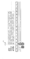
- FIG. 2 shows data on the mold number, product type, and set pouring weight of each mold M to be poured from now on.
- capacitance of the ladle 5 is 1100 kg in this embodiment.
- the mold numbers 11 to 15 are the product A and the set pouring weight is 100 kg
- the set molten metal weight of the molten metal received in the ladle 5 is 900 kg
- the number of molds that can be poured in the ladle 5 is 10 (product A with mold numbers 11 to 15 and product B with mold numbers 16 to 20). decide.
- the melting apparatus 1 is tilted in the positive direction by a tilting means (not shown).
- molten metal is supplied to the ladle 5 carried in on the 1st drive roller conveyor 4.
- FIG. The molten metal is supplied until the weight of the molten metal in the ladle 5 reaches 900 kg, which is the set molten metal weight.
- the melting device 1 is tilted in the reverse direction by tilting means (not shown). This operation is performed by a signal from a control circuit that controls the tilting of the melting device 1 so that the ladle 5 receives the molten metal of the set molten metal weight from the melting device 1.
- the operator puts an alloy for adjusting the molten metal component into the ladle 5 on the first drive roller conveyor 4 or removes the slough (slag) in the ladle 5. Then, the molten metal weight in the ladle 5 becomes larger than the set molten metal weight. That is, a molten metal having a weight larger than the set molten metal weight is received by the ladle 5.
- the weight of the molten metal in the ladle 5 at this point, that is, the actual molten metal weight of the molten metal received in the ladle 5 is set to 1000 kg.
- the ladle transport carriage 3 is caused to travel by driving means (not shown), and the ladle 5 on the first drive roller conveyor 4 is moved to the front side of the fourth drive roller conveyor 7.
- drive means (not shown) of the first drive roller conveyor 4 and the fourth drive roller conveyor 7 are operated, and the ladle 5 on the first drive roller conveyor 4 is carried onto the fourth drive roller conveyor 7.
- the ladle transport carriage 3 is caused to travel by drive means (not shown), and the first drive roller conveyor 4 is moved to the front side of the third drive roller conveyor 6.
- drive means (not shown) of the second drive roller conveyor 10 the third drive roller conveyor 6 and the first drive roller conveyor 4 are operated, and the empty ladle 5 on the second drive roller conveyor 10 is moved onto the third drive roller conveyor 6. And is carried onto the first drive roller conveyor 4.
- the ladle transport carriage 3 is caused to travel by driving means (not shown), and the empty ladle 5 on the first drive roller conveyor 4 is returned to the outside of the melting apparatus 1.
- the automatic pouring device 9 is caused to travel by driving means (not shown), and the second driving roller conveyor 10 is moved to the side opposite to the fourth driving roller conveyor 7. Thereafter, drive means (not shown) of the fourth drive roller conveyor 7 and the second drive roller conveyor 10 are operated, and the ladle 5 containing the molten metal on the fourth drive roller conveyor 7 is carried onto the second drive roller conveyor 10. .
- the difference between the actual molten metal weight of the molten metal received in the ladle 5 and the set molten metal weight is calculated by the first arithmetic circuit.
- the control panel 11 adds a part of the calculated weight difference between the actual molten metal weight of the ladle 5 and the set molten metal weight to the set molten metal weight of the mold M to be poured.
- the pouring weight is calculated by the second arithmetic circuit.
- a part of the difference in weight between the actual molten metal weight of the ladle 5 and the set molten metal weight to be added to the set molten metal weight of the mold M to be poured is that of the ladle 5.
- the weight difference between the actual molten metal weight and the set molten metal weight is divided by the number of molds that can be poured in the ladle 5.
- the mold number M to be poured first in this embodiment is mold number 11.
- the mold number 11 a value obtained by dividing the weight difference of 100 kg between the actual molten metal weight of the ladle 5 and the set molten metal weight by the number of molds that can be poured in the ladle 5, that is, 100 kg /
- the ladle 5 is tilted in the forward direction by a tilting means (not shown). Thereby, the molten metal is poured into the mold M of the mold number 11 with the target pouring weight as a target. Thereafter, the ladle 5 is tilted in the reverse direction by a tilting means (not shown). This operation is performed by a signal from a pouring circuit of the control panel 11 that pours the mold to be poured into the mold to be poured with the target pouring weight as a target.
- the mold group of the mold M is intermittently conveyed in the direction of the arrow Y1 by one pitch (one mold) by a mold conveying means (not shown). Then, the mold M to be poured becomes the mold of mold number 12.
- the ladle 5 is tilted in the forward direction by tilting means (not shown). Thereby, the molten metal is poured into the mold M of the mold number 12 with the target pouring weight as a target. Thereafter, the ladle 5 is tilted in the reverse direction by the tilting means. This operation is performed by a signal from a pouring circuit that pours the mold to be poured into the mold to be poured with the target pouring weight as a target.
- the molds M of the mold numbers 13 to 20 are intermittently conveyed sequentially in the direction of the arrow Y1, and the target pouring weight of the mold numbers 13 to 20 is the same as in the case of the mold number 12 described above. calculate. Then, molten metal is poured into each of the molds M of the mold numbers 13 to 20 with the target pouring weight as a target.
- the ladle 5 is emptied.
- the empty ladle 5 on the second drive roller conveyor 10 is replaced with a ladle 5 containing molten metal.
- the ladle 5 containing the molten metal is carried onto the third drive roller conveyor 6 and waited until the pouring of the mold No. 20 into the mold M is completed.
- the first driving roller conveyor 4 is moved to the front side of the fourth driving roller conveyor 7.
- the empty ladle 5 on the second drive roller conveyor 10 is passed over the fourth drive roller conveyor 7 and carried onto the first drive roller conveyor 4. .
- the ladle 5 containing the molten metal on the third drive roller conveyor 6 is carried onto the second drive roller conveyor 10.
- the empty ladle 5 on the first drive roller conveyor 4 is returned to the outside of the melting apparatus 1.
- the number of molds that can be poured in the ladle 5 is the same as in the above embodiment. Repeat pouring.
- the weight difference between the actual molten metal weight of the ladle 5 and the set molten metal weight is distributed to each of the molds M of the number of molds that can be poured in the ladle 5, and the molds of the respective molds M are distributed. Since the target pouring weight is calculated by adding to the set pouring weight, and the target pouring weight is poured into each of the molds M, the last number of molds that can be poured in the ladle 5 is reached. When the mold M is poured into the mold M, there is an effect that the ladle 5 can be surely emptied. For this reason, generation
- the present invention is not limited to this.
- a part of the weight difference between the actual molten metal weight of the ladle 5 and the set molten metal weight to be added to the set molten metal weight of the mold M to be poured is used as the ladle.
- the value d obtained by dividing the weight difference between the actual molten metal weight of 5 and the set molten metal weight by the number of molds that can be poured into the ladle 5 is d, the present invention is not limited to this.
- the weight difference between the actual molten metal weight of the ladle 5 and the set molten metal weight is the number of molds M that can be poured in the ladle 5.
- the target pouring weight can be calculated by accurately distributing to each and adding to the set pouring weight of each mold M, thereby reducing the variation in the target pouring weight for each mold M. Therefore, it is more preferable.
- the present invention is not limited to this, and there is no horizontal split frame.
- the present invention can also be applied to the pouring of a frameless mold molded by a molding machine, a frameless mold molded by a vertical frameless molding machine, and the like.
Landscapes
- Engineering & Computer Science (AREA)
- Mechanical Engineering (AREA)
- Casting Support Devices, Ladles, And Melt Control Thereby (AREA)
Abstract
Description
注湯すべき前記鋳型群の各々の鋳型の鋳型番号、鋳造すべき製品の種別、設定注湯重量のデータを前記制御手段へ与える工程と、
前記与えられた各々の鋳型の鋳型番号、製品の種別、設定注湯重量のデータに基づき、前記取鍋で受湯する溶湯の設定溶湯重量及び前記取鍋で注湯可能な鋳型数を前記制御手段で決定する工程と、
前記設定溶湯重量より多くの重量の溶湯を前記取鍋で受湯する工程と、
該取鍋で受湯した溶湯の実際溶湯重量と前記設定溶湯重量との差を算出する工程と、
該算出した取鍋の前記実際溶湯重量と前記設定溶湯重量との重量差の一部を、注湯すべき鋳型の前記設定注湯重量に加算して目標注湯重量を算出する工程と、
前記取鍋を傾動させることにより、前記注湯すべき鋳型に前記目標注湯重量を目標として注湯する工程と、を含み、
前記取鍋で注湯可能な鋳型数だけ前記注湯を繰り返し、該注湯可能な鋳型数の最後の鋳型に注湯したときに前記取鍋を空にすることを特徴とする。
また、本発明の自動注湯設備は、各種金属を溶融させて溶湯にする溶解装置と、
前記溶解装置から受湯した溶湯を内部に貯留する取鍋を傾動させることにより、間欠搬送されてくる鋳型群のうちの所定の鋳型内に溶湯を注湯する自動注湯装置と、
前記溶解装置と前記自動注湯装置との間で前記取鍋を搬送する台車と、
前記溶解装置および前記台車および自動注湯装置をそれぞれ制御する制御手段とからなる自動注湯設備において、
前記制御手段が、
注湯すべき前記鋳型群の各々の鋳型の鋳型番号、鋳造すべき製品の種別、設定注湯重量のデータを与えられる入力回路と、
前記与えられた各々の鋳型の鋳型番号、製品の種別、設定注湯重量のデータに基づき、前記取鍋で前記溶解装置から受湯すべき溶湯の設定溶湯重量及び前記取鍋で注湯可能な鋳型数を決定する決定回路と、
前記溶解装置から前記設定溶湯重量の溶湯を前記取鍋で受湯するように前記溶解装置の傾動を制御する制御回路と、
該取鍋で受湯した溶湯の実際溶湯重量と前記設定溶湯重量との差を算出する第1の演算回路と、
該算出した取鍋の前記実際溶湯重量と前記設定溶湯重量との重量差の一部を注湯すべき鋳型の前記設定注湯重量に加算して目標注湯重量を算出する第2の演算回路と、
前記取鍋を傾動させることにより、前記注湯すべき鋳型に前記目標注湯重量を目標として注湯する注湯回路と、を含み、
前記取鍋で注湯可能な鋳型数だけ前記注湯を繰り返し、該注湯可能な鋳型数の最後の鋳型に注湯したときに前記取鍋を空にすることを特徴とする。
ただし、上述の実施形態のように求めた値dを用いると、取鍋5の前記実際溶湯重量と前記設定溶湯重量との重量差を該取鍋5で注湯可能な鋳型数の鋳型Mの各々に精度よく分配して該各々の鋳型Mの前記設定注湯重量に加算して目標注湯重量を算出することができ、これにより鋳型M毎の目標注湯重量の大小のバラツキが少なくなるため、より好ましい。
Claims (7)
- 内部に溶湯を貯留する取鍋を傾動させることにより、間欠搬送されてくる鋳型群のうちの所定の鋳型内に溶湯を注湯する自動注湯装置と該自動注湯装置を制御する制御手段とを用いた自動注湯方法であって、
注湯すべき前記鋳型群の各々の鋳型の鋳型番号、鋳造すべき製品の種別、設定注湯重量のデータを前記制御手段へ与える工程と、
前記与えられた各々の鋳型の鋳型番号、製品の種別、設定注湯重量のデータに基づき、前記取鍋で受湯する溶湯の設定溶湯重量及び前記取鍋で注湯可能な鋳型数を前記制御手段で決定する工程と、
前記設定溶湯重量より多くの重量の溶湯を前記取鍋で受湯する工程と、
該取鍋で受湯した溶湯の実際溶湯重量と前記設定溶湯重量との差を算出する工程と、
該算出した取鍋の前記実際溶湯重量と前記設定溶湯重量との重量差の一部を、注湯すべき鋳型の前記設定注湯重量に加算して目標注湯重量を算出する工程と、
前記取鍋を傾動させることにより、前記注湯すべき鋳型に前記目標注湯重量を目標として注湯する工程と、を含み、
前記取鍋で注湯可能な鋳型数だけ前記注湯を繰り返し、該注湯可能な鋳型数の最後の鋳型に注湯したときに前記取鍋を空にすることを特徴とする自動注湯方法。 - 前記注湯すべき鋳型の前記設定注湯重量に加算する前記取鍋の前記実際溶湯重量と前記設定溶湯重量との重量差の一部が、前記取鍋の前記実際溶湯重量と前記設定溶湯重量との重量差を前記取鍋で注湯可能な鋳型数で除した値であることを特徴とする請求項1記載の自動注湯方法。
- 各種金属を溶融させて溶湯にする溶解装置と、
前記溶解装置から受湯した溶湯を内部に貯留する取鍋を傾動させることにより、間欠搬送されてくる鋳型群のうちの所定の鋳型内に溶湯を注湯する自動注湯装置と、
前記溶解装置と前記自動注湯装置との間で前記取鍋を搬送する台車と、
前記溶解装置および前記台車および自動注湯装置をそれぞれ制御する制御手段とからなる自動注湯設備において、
前記制御手段が、
注湯すべき前記鋳型群の各々の鋳型の鋳型番号、鋳造すべき製品の種別、設定注湯重量のデータを与えられる入力回路と、
前記与えられた各々の鋳型の鋳型番号、製品の種別、設定注湯重量のデータに基づき、前記取鍋で前記溶解装置から受湯すべき溶湯の設定溶湯重量及び前記取鍋で注湯可能な鋳型数を決定する決定回路と、
前記溶解装置から前記設定溶湯重量の溶湯を前記取鍋で受湯するように前記溶解装置の傾動を制御する制御回路と、
該取鍋で受湯した溶湯の実際溶湯重量と前記設定溶湯重量との差を算出する第1の演算回路と、
該算出した取鍋の前記実際溶湯重量と前記設定溶湯重量との重量差の一部を注湯すべき鋳型の前記設定注湯重量に加算して目標注湯重量を算出する第2の演算回路と、
前記取鍋を傾動させることにより、前記注湯すべき鋳型に前記目標注湯重量を目標として注湯する注湯回路と、を含み、
前記取鍋で注湯可能な鋳型数だけ前記注湯を繰り返し、該注湯可能な鋳型数の最後の鋳型に注湯したときに前記取鍋を空にすることを特徴とする自動注湯設備。 - 前記注湯すべき鋳型の前記設定注湯重量に加算する前記取鍋の前記実際溶湯重量と前記設定溶湯重量との重量差の一部が、前記取鍋の前記実際溶湯重量と前記設定溶湯重量との重量差を前記取鍋で注湯可能な鋳型数で除した値であることを特徴とする請求項3記載の自動注湯設備。
- 前記取鍋を搬送する台車は、
前記取鍋内の溶湯重量を計量する重量計量手段と、
第1駆動ローラコンベヤとを有し、該第1駆動ローラコンベヤに前記取鍋を搬入出することを特徴とする請求項3記載の自動注湯設備。 - 前記自動注湯装置は、
前記取鍋内の溶湯重量を計量する重量計量手段と、
第2駆動ローラコンベヤとを有し、該第2駆動ローラコンベヤに前記取鍋を搬入出することを特徴とする請求項3記載の自動注湯設備。 - 前記溶解装置の外側に敷設された第1レールと、
前記第1レールの外側に配設された第3駆動ローラコンベヤ及び第4駆動ローラコンベヤと、
該第3駆動ローラコンベヤ及び第4駆動ローラコンベヤの外側に敷設された第2レールと、を更に備え、
前記台車は前記第1レール上に走行可能に載置され、
前記自動注湯装置は前記第2レール上に走行可能に載置されている請求項3記載の自動注湯設備。
Priority Applications (3)
| Application Number | Priority Date | Filing Date | Title |
|---|---|---|---|
| EP10789286.1A EP2444178B1 (en) | 2009-06-16 | 2010-03-25 | Automatic pouring method and facility therefor |
| CN2010800268763A CN102802842A (zh) | 2009-06-16 | 2010-03-25 | 自动浇注方法及其设备 |
| US13/378,606 US9008819B2 (en) | 2009-06-16 | 2010-03-25 | Automatic pouring method and facility therefor |
Applications Claiming Priority (4)
| Application Number | Priority Date | Filing Date | Title |
|---|---|---|---|
| JP2009143077 | 2009-06-16 | ||
| JP2009-143077 | 2009-06-16 | ||
| JP2010-013798 | 2010-01-26 | ||
| JP2010013798A JP2011020176A (ja) | 2009-06-16 | 2010-01-26 | 自動注湯方法およびその設備 |
Publications (1)
| Publication Number | Publication Date |
|---|---|
| WO2010146909A1 true WO2010146909A1 (ja) | 2010-12-23 |
Family
ID=43356238
Family Applications (1)
| Application Number | Title | Priority Date | Filing Date |
|---|---|---|---|
| PCT/JP2010/055174 Ceased WO2010146909A1 (ja) | 2009-06-16 | 2010-03-25 | 自動注湯方法およびその設備 |
Country Status (5)
| Country | Link |
|---|---|
| US (1) | US9008819B2 (ja) |
| EP (1) | EP2444178B1 (ja) |
| JP (1) | JP2011020176A (ja) |
| CN (1) | CN102802842A (ja) |
| WO (1) | WO2010146909A1 (ja) |
Families Citing this family (14)
| Publication number | Priority date | Publication date | Assignee | Title |
|---|---|---|---|---|
| JP5886686B2 (ja) * | 2012-05-25 | 2016-03-16 | 東久株式会社 | 自動注湯装置並びに鋳型に対する注湯方法 |
| CN103042202B (zh) * | 2013-01-24 | 2014-07-16 | 宁波禾顺新材料有限公司 | 一种自动浇注系统 |
| CN103658620B (zh) * | 2013-11-29 | 2016-02-10 | 安徽省宁国市宁沪钢球有限公司 | 一种流量控制型钢球成型模具自动进料系统及其控制方法 |
| US20170326636A1 (en) * | 2014-11-26 | 2017-11-16 | Sintokogio, Ltd. | Automatic pouring machine and method for automtically pouring that have ability to pressurize |
| CN105033231A (zh) * | 2015-07-10 | 2015-11-11 | 成都亨通兆业精密机械有限公司 | 一种高效环规铸造装置 |
| CN106077601A (zh) * | 2016-08-24 | 2016-11-09 | 苏州苏铸成套装备制造有限公司 | 一种全自动浇注机以及对应的工作方法 |
| CN106694863B (zh) * | 2016-12-29 | 2019-04-23 | 中冶京诚工程技术有限公司 | 钢水浇注的控制方法及装置 |
| JP6995709B2 (ja) * | 2018-07-06 | 2022-01-17 | 新東工業株式会社 | 鋳鋼鋳物製造システム |
| CN109396406A (zh) * | 2018-12-31 | 2019-03-01 | 兴化市精锐机械有限公司 | 一种智能精密浇铸系统 |
| CN111215611B (zh) * | 2020-02-21 | 2021-06-15 | 太原科技大学 | 一种消失模铸造自动浇注系统 |
| JP2023033113A (ja) * | 2021-08-27 | 2023-03-09 | 新東工業株式会社 | 鋳造設備制御システム |
| CN114054740B (zh) * | 2021-09-22 | 2023-05-05 | 山东杰创机械有限公司 | 一种多工位协同浇注系统的浇注方法 |
| CN116213701B (zh) * | 2023-02-16 | 2025-11-04 | 山东杰创机械有限公司 | 一种集成化的金属熔液浇注系统及浇注方法 |
| CN116251948A (zh) * | 2023-03-12 | 2023-06-13 | 浙江省机电设计研究院有限公司 | 适合铁型覆砂生产的铁水转运系统及其工作方法 |
Citations (4)
| Publication number | Priority date | Publication date | Assignee | Title |
|---|---|---|---|---|
| JPH01262064A (ja) * | 1988-04-14 | 1989-10-18 | Hitachi Metals Ltd | 注湯完了枠数自動計測方法 |
| JPH0446665A (ja) | 1990-06-12 | 1992-02-17 | Mazda Motor Corp | 自動注湯機 |
| JPH11207458A (ja) * | 1998-01-22 | 1999-08-03 | Kubota Corp | 小ロット混合生産用自動注湯装置 |
| JP2000102859A (ja) * | 1998-09-28 | 2000-04-11 | Toyota Motor Corp | 鋳造方法及びそれに用いる鋳造ライン |
Family Cites Families (2)
| Publication number | Priority date | Publication date | Assignee | Title |
|---|---|---|---|---|
| US4600047A (en) * | 1984-03-29 | 1986-07-15 | Sumitomo Metal Industries, Ltd. | Process for controlling the molten metal level in continuous thin slab casting |
| TWI466740B (zh) * | 2007-02-15 | 2015-01-01 | 新東工業股份有限公司 | 自動注入方法及裝置 |
-
2010
- 2010-01-26 JP JP2010013798A patent/JP2011020176A/ja active Pending
- 2010-03-25 EP EP10789286.1A patent/EP2444178B1/en active Active
- 2010-03-25 WO PCT/JP2010/055174 patent/WO2010146909A1/ja not_active Ceased
- 2010-03-25 US US13/378,606 patent/US9008819B2/en active Active
- 2010-03-25 CN CN2010800268763A patent/CN102802842A/zh active Pending
Patent Citations (4)
| Publication number | Priority date | Publication date | Assignee | Title |
|---|---|---|---|---|
| JPH01262064A (ja) * | 1988-04-14 | 1989-10-18 | Hitachi Metals Ltd | 注湯完了枠数自動計測方法 |
| JPH0446665A (ja) | 1990-06-12 | 1992-02-17 | Mazda Motor Corp | 自動注湯機 |
| JPH11207458A (ja) * | 1998-01-22 | 1999-08-03 | Kubota Corp | 小ロット混合生産用自動注湯装置 |
| JP2000102859A (ja) * | 1998-09-28 | 2000-04-11 | Toyota Motor Corp | 鋳造方法及びそれに用いる鋳造ライン |
Also Published As
| Publication number | Publication date |
|---|---|
| US9008819B2 (en) | 2015-04-14 |
| EP2444178A1 (en) | 2012-04-25 |
| US20120173009A1 (en) | 2012-07-05 |
| EP2444178A4 (en) | 2017-05-17 |
| EP2444178B1 (en) | 2020-11-11 |
| JP2011020176A (ja) | 2011-02-03 |
| CN102802842A (zh) | 2012-11-28 |
Similar Documents
| Publication | Publication Date | Title |
|---|---|---|
| JP2011020176A (ja) | 自動注湯方法およびその設備 | |
| JP5627127B2 (ja) | 自動注湯機への溶湯供給方法およびその設備 | |
| JP5519679B2 (ja) | 注湯機制御システム、注湯設備及び注湯方法 | |
| JP6472899B2 (ja) | 鋳造設備および鋳造設備における鋳型の造型データと溶湯の溶湯状態データの管理方法 | |
| TW202003136A (zh) | 管理系統及管理方法 | |
| JP6624100B2 (ja) | 鋳造設備を構成する複数の装置の異常の原因を検出するシステム | |
| JP4492757B1 (ja) | 注湯設備および注湯方法 | |
| WO2019064726A1 (ja) | 鋳造ラインにおける動作不良の検出方法及び装置 | |
| JP2009202215A (ja) | 注湯設備 | |
| JP5408797B2 (ja) | 注湯設備 | |
| CN104755195B (zh) | 向铸型浇注的熔融金属的取样装置以及取样方法和材质管理方法 | |
| CN115722658A (zh) | 铸造设备 | |
| JP2808121B2 (ja) | 鋳造ライン制御方法 | |
| JP6818979B2 (ja) | 製鋼工程における排滓ポットの交換タイミングの導出方法 | |
| JP6642020B2 (ja) | 連続鋳造設備の鋳造速度制御方法及び鋳造速度制御装置 | |
| JP6648365B2 (ja) | 連続鋳造の開始時刻の決定方法 | |
| KR101181829B1 (ko) | 합금철 투입 제어장치 및 방법 | |
| JPS62259662A (ja) | 連続鋳造システム | |
| CN121223072A (zh) | 连铸设备及其控制方法 |
Legal Events
| Date | Code | Title | Description |
|---|---|---|---|
| WWE | Wipo information: entry into national phase |
Ref document number: 201080026876.3 Country of ref document: CN |
|
| 121 | Ep: the epo has been informed by wipo that ep was designated in this application |
Ref document number: 10789286 Country of ref document: EP Kind code of ref document: A1 |
|
| WWE | Wipo information: entry into national phase |
Ref document number: 5036/KOLNP/2011 Country of ref document: IN Ref document number: 2010789286 Country of ref document: EP |
|
| NENP | Non-entry into the national phase |
Ref country code: DE |
|
| WWE | Wipo information: entry into national phase |
Ref document number: 13378606 Country of ref document: US |
|
| REG | Reference to national code |
Ref country code: BR Ref legal event code: B01A Ref document number: PI1013819 Country of ref document: BR |
|
| ENP | Entry into the national phase |
Ref document number: PI1013819 Country of ref document: BR Kind code of ref document: A2 Effective date: 20111216 |