WO2010146938A1 - Dispositif de station mobile, dispositif de station de base, système de communication, procédé de communication et programme de commande - Google Patents
Dispositif de station mobile, dispositif de station de base, système de communication, procédé de communication et programme de commande Download PDFInfo
- Publication number
- WO2010146938A1 WO2010146938A1 PCT/JP2010/057265 JP2010057265W WO2010146938A1 WO 2010146938 A1 WO2010146938 A1 WO 2010146938A1 JP 2010057265 W JP2010057265 W JP 2010057265W WO 2010146938 A1 WO2010146938 A1 WO 2010146938A1
- Authority
- WO
- WIPO (PCT)
- Prior art keywords
- transmission
- station apparatus
- uplink
- signal
- mobile station
- Prior art date
- Legal status (The legal status is an assumption and is not a legal conclusion. Google has not performed a legal analysis and makes no representation as to the accuracy of the status listed.)
- Ceased
Links
Images







Classifications
-
- H—ELECTRICITY
- H04—ELECTRIC COMMUNICATION TECHNIQUE
- H04W—WIRELESS COMMUNICATION NETWORKS
- H04W52/00—Power management, e.g. Transmission Power Control [TPC] or power classes
- H04W52/04—Transmission power control [TPC]
- H04W52/38—TPC being performed in particular situations
- H04W52/42—TPC being performed in particular situations in systems with time, space, frequency or polarisation diversity
-
- H—ELECTRICITY
- H04—ELECTRIC COMMUNICATION TECHNIQUE
- H04W—WIRELESS COMMUNICATION NETWORKS
- H04W88/00—Devices specially adapted for wireless communication networks, e.g. terminals, base stations or access point devices
- H04W88/02—Terminal devices
Definitions
- the present invention relates to a technology in which a base station apparatus and a mobile station apparatus perform wireless communication using a plurality of element frequency bands having a predetermined frequency bandwidth.
- EUTRA Evolved Universal Terrestrial Radio Access
- transmission power control is applied in the uplink.
- EUTRA uplink transmission power control the average transmission power of SC-FDMA symbols is controlled, and both an open loop transmission power control method and a closed loop transmission power control method are used.
- A-EUTRA it has been studied to support a wider frequency band than EUTRA and to ensure compatibility with EUTRA, and the base station apparatus uses one unit (hereinafter referred to as an element) of EUTRA frequency band. It is called a frequency band, and a carrier element: CarrierCarComponent or a component carrier: Component Carrier) may be used to construct a wireless communication system from a plurality of component frequency bands (frequency band aggregation: Spectrum Aggregation). Or carrier aggregation (sometimes referred to as Carrier Aggregation)) is being studied in A-EUTRA.
- the base station apparatus communicates with a mobile station apparatus compatible with EUTRA using any one element frequency band, and communicates with a mobile station apparatus compatible with A-EUTRA using one or more element frequency bands.
- NxDFT Discrete Fourier Transform
- S-OFDM Orthogonal Frequency Division Multiplexing
- the NxDFT-S-OFDM scheme is a scheme in which a DFT-S-OFDM scheme is used in each element frequency band, a mobile station apparatus transmits a signal using a plurality of element frequency bands, and a base station apparatus receives a signal. is there.
- A-EUTRA when a mobile station apparatus transmits a signal using radio resources of a plurality of element frequency bands, the communication quality (reception quality, communication speed, etc.) is the same as when the mobile station apparatus is EUTRA in each element frequency band. If it is going to implement
- a mobile station apparatus amplifies a signal using a power amplifier and transmits the signal.
- the waveform of the transmission signal is distorted, and the mobile station apparatus Cannot transmit a suitable signal, it is necessary to set an upper limit value of the transmission power and appropriately control the average input value of the signal to the power amplifier.
- the mobile station apparatus transmits a signal using the set upper limit value of transmission power, there is a problem in that the transmission power necessary for signal transmission is insufficient and appropriate communication quality cannot be realized. .
- the mobile station apparatus transmits signals by operating as few power amplifiers as possible.
- An object of the present invention is to provide a mobile station device, a base station device, a communication system, a communication method, and a control program that can transmit a signal having a communication quality suitable for a wireless communication system.
- the mobile station apparatus of the present invention is a mobile station apparatus that performs radio communication with a base station apparatus using a plurality of element frequency bands having a predetermined frequency bandwidth, and includes a plurality of transmission antennas and power amplifiers.
- a transmission mode or each element frequency band in which a transmission signal is generated using radio resources of a plurality of element frequency bands and a signal of each element frequency band is transmitted using a single transmission antenna.
- a transmission processing unit that outputs the generated transmission signal to at least one transmission unit based on information indicating either one of the second transmission modes for transmitting signals using different transmission antennas,
- the transmission signal is wirelessly transmitted to the base station apparatus in either of the transmission mode or the second transmission mode.
- the present invention can wirelessly transmit a transmission signal to the base station apparatus in either the first transmission mode or the second transmission mode, the mobile station apparatus Accordingly, the number of antennas to be used can be controlled, and a signal with communication quality suitable for the wireless communication system can be transmitted.
- the mobile station apparatus further includes a control unit that measures transmission power reserve of a plurality of power amplifiers, and the transmission unit wirelessly transmits information indicating the transmission power reserve to the base station apparatus. It is characterized by that.
- the base station apparatus since the mobile station apparatus wirelessly transmits information indicating the transmission power reserve of the plurality of power amplifiers to the base station apparatus, the base station apparatus selects a transmission mode based on the transmission power reserve of the mobile station apparatus. can do.
- the mobile station apparatus of the present invention further includes a transmission power control unit that performs transmission power control according to the first transmission mode or the second transmission mode for each element frequency band. To do.
- the mobile station apparatus since the mobile station apparatus performs transmission power control according to the first transmission mode or the second transmission mode for each element frequency band, in the case of EUTRA while controlling the number of antennas used for transmission.
- the transmission power control can be performed in the same manner as in FIG. This enables communication with reduced power consumption while maintaining communication quality.
- the transmission power control unit sets the upper limit value of the average transmission power of each power amplifier to a different value depending on the first transmission mode or the second transmission mode. It is characterized by that.
- the PAPR caused by the difference between the single carrier signal and the multicarrier signal is set.
- the input value to the power amplifier in the transmission RF unit can be set to an appropriate value.
- the transmission power control unit sets the upper limit value of the average transmission power to the second transmission It is characterized in that it is set to a value smaller than the mode.
- the upper limit value of the average transmission power is set to a value smaller than that in the second transmission mode.
- An input value to the power amplifier can be set to an appropriate value.
- the PAPR increase generated in the NxDFT-S-OFDM multicarrier signal as in the first transmission mode is more controlled than in the second transmission mode, and the power in the transmission RF unit is increased. It is possible to reduce the situation where the input value to the amplifier exceeds the capacity of the power amplifier.
- the scrambling included in the downlink control information and applied to the cyclic redundancy check is applied to the downlink control information for each element frequency band received from the base station apparatus.
- a control unit that selects the first transmission mode when the scrambling code being used is common in each element frequency band, and that selects the second transmission mode when different in each element frequency band;
- the transmission signal is wirelessly transmitted to the base station apparatus in either the selected first transmission mode or second transmission mode.
- the downlink control channel can be used without using the downlink shared channel by selecting the transmission mode depending on whether the scrambling code included in the downlink control information and applied to the cyclic redundancy check is common or different.
- Information about the transmission mode can be transmitted.
- the first transmission mode is selected.
- a control unit that selects the second transmission mode is provided, and the selected first transmission mode or second transmission mode is provided. Any one of the above is characterized in that a transmission signal is wirelessly transmitted to the base station apparatus.
- the first transmission mode is selected, while the sum of the average transmission power is
- the maximum power of any one of the power amplifiers is exceeded, by selecting the second transmission mode, the number of transmission antennas can be set as small as possible while performing appropriate power control. Thereby, power consumption can be reduced.
- a base station apparatus of the present invention is a base station apparatus that performs radio communication with a mobile station apparatus using a plurality of element frequency bands having a predetermined frequency bandwidth, and includes a plurality of elements from the mobile station apparatus. Based on a reception processing unit that receives a signal transmitted using radio resources in the frequency band and a parameter related to transmission power notified from the mobile station device, signals in each element frequency band are transmitted using a single transmission antenna.
- the base station side control unit for selecting either the first transmission mode to be transmitted or the second transmission mode for transmitting signals in each element frequency band using different transmission antennas, and the selected first transmission
- a base station side transmitting unit that wirelessly transmits information indicating either the mode or the second transmission mode to the mobile station apparatus.
- the base station apparatus transmits a signal in each element frequency band using a single transmission antenna, or transmits a signal in each element frequency band using a different transmission antenna.
- information indicating the transmission mode can be transmitted to the mobile station apparatus.
- the mobile station apparatus can control the number of antennas to be used, and can transmit a signal of communication quality suitable for the radio communication system.
- the parameter related to transmission power is a transmission power remaining capacity of a plurality of power amplifiers included in the mobile station apparatus.
- the parameter related to transmission power is the transmission power remaining capacity of a plurality of power amplifiers, it is possible to control the transmission power within a range of power that can be handled by the power amplifier.
- control unit is configured such that the sum of average transmission powers for a plurality of element frequency bands set in the mobile station apparatus is any one of the power amplifiers based on the transmission power surplus capacity. If the maximum transmission power does not exceed the maximum transmission power, the first transmission mode is selected, while if the sum of the average transmission power exceeds the maximum power of any one of the power amplifiers, the second transmission mode is selected.
- the first transmission mode is selected while the average
- the number of transmission antennas can be set as small as possible while performing appropriate power control by selecting the second transmission mode. it can. Thereby, power consumption can be reduced.
- a communication system is a communication system in which a mobile station apparatus and a base station apparatus perform wireless communication using a plurality of element frequency bands having a predetermined frequency bandwidth.
- a reception processing unit that receives a signal transmitted from a mobile station apparatus using radio resources in a plurality of element frequency bands, and a signal in each element frequency band based on a parameter related to transmission power notified from the mobile station apparatus.
- a base station-side control unit that selects either a first transmission mode for transmitting using a single transmission antenna or a second transmission mode for transmitting signals in each element frequency band using different transmission antennas;
- a base station side transmitter that wirelessly transmits information indicating either the selected first transmission mode or the second transmission mode to the mobile station apparatus, and
- the station apparatus transmits a generated transmission signal to at least one transmission unit based on a plurality of transmission units having a transmission antenna and a power amplifier and information indicating either the first transmission mode or the second transmission mode.
- a transmission processing unit for outputting, wherein the mobile station apparatus wirelessly transmits a transmission signal to the base station apparatus in either the first transmission mode or the second transmission mode.
- the mobile station apparatus wirelessly transmits a transmission signal to the base station apparatus in either the first transmission mode or the second transmission mode, the mobile station apparatus responds to the state of the transmission signal.
- the number of antennas to be used can be controlled, and a signal having a communication quality suitable for a wireless communication system can be transmitted.
- a communication method of the present invention is a communication method of a communication system in which a mobile station apparatus and a base station apparatus perform wireless communication using a plurality of element frequency bands having a predetermined frequency bandwidth, In the station apparatus, a signal received from the mobile station apparatus using radio resources of a plurality of element frequency bands, and a signal in each element frequency band based on a parameter related to transmission power notified from the mobile station apparatus Selecting a first transmission mode for transmitting using a single transmission antenna or a second transmission mode for transmitting signals of each element frequency band using different transmission antennas, and Wirelessly transmitting information indicating either the first transmission mode or the second transmission mode to the mobile station apparatus, and In the mobile station apparatus, based on the information indicating either the first transmission mode or the second transmission mode, the step of outputting the generated transmission signal to at least one of the transmission units, the first transmission mode or Wirelessly transmitting a transmission signal to the base station apparatus in any one of the second transmission modes.
- the mobile station apparatus wirelessly transmits a transmission signal to the base station apparatus in either the first transmission mode or the second transmission mode, the mobile station apparatus responds to the state of the transmission signal.
- the number of antennas to be used can be controlled, and a signal having a communication quality suitable for a wireless communication system can be transmitted.
- a control program of the present invention is a control program for a mobile station apparatus that performs radio communication with a base station apparatus using a plurality of element frequency bands having a predetermined frequency bandwidth
- the transmission processing unit includes: A transmission signal is generated using radio resources of a plurality of element frequency bands, and a signal in each element frequency band is transmitted using a single transmission antenna. Based on information indicating either one of the second transmission modes transmitted using the antenna, processing for outputting the generated transmission signal to at least one transmission unit, and the transmission unit in the first transmission mode or the second transmission mode A process of wirelessly transmitting a transmission signal to the base station apparatus in any one of the transmission modes of Characterized in that the de of.
- the mobile station apparatus wirelessly transmits a transmission signal to the base station apparatus in either the first transmission mode or the second transmission mode, the mobile station apparatus responds to the state of the transmission signal.
- the number of antennas to be used can be controlled, and a signal having a communication quality suitable for a wireless communication system can be transmitted.
- the present invention in a wireless communication system using a plurality of element frequency bands, it is possible to transmit a signal of communication quality suitable for the wireless communication system while suppressing power consumption.
- FIG. It is a figure explaining the outline about the whole picture of the radio communications system concerning the embodiment of the present invention. It is a figure which shows schematic structure of the downlink radio
- W-CDMA Wideband Code Division Multiple Access
- 3GPP 3rd Generation Partnership Project
- EUTRA 3th Generation Partnership Project
- 3G network evolution Evolved Universal Terrestrial Radio Access Network
- the OFDM scheme that is multicarrier transmission is applied.
- the DFT-Spread OFDM scheme, which is single carrier transmission is applied in the uplink, which is the communication direction from the EUTRA mobile station apparatus to the base station apparatus.
- EUTRA UpLink Transmit Power Control
- transmission power control is applied in the uplink.
- EUTRA uplink transmission power control the average transmission power of SC-FDMA symbols is controlled, and both an open loop transmission power control method and a closed loop transmission power control method are used.
- the open loop transmission power control method is a method in which the mobile station apparatus controls transmission power according to the strength of the signal from the base station apparatus received by the mobile station apparatus.
- transmission power is controlled based on a path loss calculated from received power of a downlink reference signal received by a mobile station apparatus.
- the closed loop transmission power control method sets a transmission power control value according to the strength of a signal from a mobile station apparatus received by a base station apparatus, and transmits the transmission power control value to the mobile station apparatus using a downlink control channel.
- This is a method of controlling transmission power according to a transmission power control value included in a downlink control channel that is transmitted and received by a mobile station apparatus.
- EUTRA a method in which a mobile station apparatus controls transmission power using a value obtained by accumulating transmission power control values notified from a base station apparatus in a plurality of downlink subframes, and the mobile station apparatus has one downlink subframe.
- a transmission power control value transmitted from a base station apparatus to a mobile station apparatus using a downlink control channel indicating radio resource allocation of an uplink shared data channel is composed of 2 bits.
- a transmission power control value [ dB] indicates any value of ⁇ 1, 0, 1, 3 ⁇ , and the mobile station apparatus uses the transmission power control value notified from the base station apparatus in one downlink subframe as it is.
- the transmission power control value [dB] transmitted from the base station apparatus indicates any value of ⁇ 4, ⁇ 1, 1, 4 ⁇ .
- the number of uplink resource block pairs allocated to the uplink shared data channel A modulation scheme dependent power offset value based on a modulation scheme applied to the uplink shared data channel, a reference transmission power control value notified to the mobile station apparatus using the downlink shared data channel at the time of communication connection,
- the mobile station apparatus broadcasts and transmits the path loss measured by the mobile station apparatus using the link shared data channel to the mobile station apparatus within the communication area of the base station apparatus, and the mobile station apparatus averages the SC-FDMA symbols. Control transmission power.
- the mobile station apparatus compares the transmission power value calculated based on the above parameters with the allowable maximum transmission power value of the average transmission power of the own apparatus, and sets the transmission power using a low value.
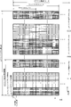
- the downlink radio frame is a unit for radio resource allocation or the like, and is composed of a downlink resource block pair having a frequency band and a time band having a predetermined width.
- One downlink resource block pair is composed of two downlink resource blocks that are continuous in the time domain.
- One downlink resource block is composed of 12 downlink subcarriers in the frequency domain, and is composed of 7 OFDM symbols in the time domain.
- the frequency bandwidth used for downlink communication of the base station apparatus is referred to as a downlink system bandwidth.
- In the time domain there are downlink slots composed of 7 OFDM symbols, downlink subframes composed of 2 downlink slots, and downlink radio frames composed of 10 downlink subframes. .
- a unit composed of one downlink subcarrier and one OFDM symbol is called a downlink resource element.
- a plurality of downlink resource blocks are arranged according to the downlink system bandwidth.
- each downlink subframe at least a downlink shared data channel used for transmitting information data and a downlink control channel used for transmitting control data are arranged. Also, downlink reference signals of downlink pilot channels used for propagation path estimation of the downlink shared data channel and downlink control channel are distributed and arranged in a plurality of downlink resource elements.
- the downlink reference signal is a known signal used for the downlink pilot channel.
- Downlink control channel includes mobile station identifier, downlink shared data channel radio resource allocation information, uplink shared data channel radio resource allocation information, uplink shared data channel transmission power control value, multi-antenna related information, modulation scheme
- a signal generated from control data such as a coding rate and a retransmission parameter is arranged.
- the uplink radio frame is a unit such as radio resource allocation, and is composed of an uplink resource block pair consisting of a frequency band and a time band having a predetermined width.
- One uplink resource block pair is composed of two uplink resource blocks that are continuous in the time domain.
- one uplink resource block is composed of 12 uplink subcarriers in the frequency domain, and is composed of 7 SC-FDMA (Single Carrier-Frequency Division Multiple Multiple Access) symbols in the time domain.
- the frequency bandwidth used for uplink communication of the base station apparatus is referred to as an uplink system bandwidth.
- a plurality of uplink resource blocks are arranged according to the uplink system bandwidth.
- an uplink slot composed of 7 SC-FDMA symbols, an uplink subframe composed of 2 uplink slots, and an uplink composed of 10 uplink subframes There is a radio frame.
- a unit composed of one uplink subcarrier and one SC-FDMA symbol is called an uplink resource element.
- each uplink subframe at least an uplink shared data channel used for transmitting information data and an uplink control channel used for transmitting control data are arranged.
- the uplink control channel is control data including a downlink channel quality index CQI (Channel Quality Indicator), a reception response ACK / NACK (Acknowledgement / Negative-Acknowledgement) for the downlink shared data channel, or a scheduling request SR (Scheduling Request).
- CQI Channel Quality Indicator
- ACK / NACK Acknowledgement / Negative-Acknowledgement
- Send Send.
- the uplink control channel is used for transmission of control data consisting of channel quality indicator CQI, is used for transmission of control data consisting of reception response ACK / NACK, and transmission of control data consisting of scheduling request SR.
- control data consisting of channel quality indicator CQI
- reception response ACK / NACK is used for transmission of control data consisting of reception response ACK / NACK
- control data consisting of scheduling request SR.
- Different types of uplink control channels are used depending on the case used for. Note that different types of uplink control channels have different signal configurations.
- the uplink resource block pair used for the uplink control channel is composed of two uplink resource blocks that are symmetrical in the frequency domain and are located in different uplink slots. Also, different uplink control channel signals are code-multiplexed in one uplink resource block.
- An uplink pilot channel used for propagation path estimation of the uplink shared data channel and the uplink control channel is arranged in the same uplink resource block as the uplink shared data channel, and the same uplink as the uplink control channel.
- an uplink reference signal is arranged in SC-FDMA symbols at different positions.
- the uplink reference signal is a known signal used for the uplink pilot channel.
- the uplink reference signal is arranged in the SC-FDMA symbol at the fourth position in the uplink slot.
- the SCs at the second and sixth positions in the uplink slot are used.
- -An uplink reference signal is arranged in the FDMA symbol.
- the uplink pilot channel When the uplink pilot channel is arranged in the same uplink resource block as the uplink control channel used for transmission of control data including reception response ACK / NACK, the third, fourth, and fifth in the uplink slot An uplink reference signal is arranged in the SC-FDMA symbol at the position.
- the uplink pilot channel is arranged in the same uplink resource block as the uplink control channel used for transmission of control data including the scheduling request SR, the third, fourth, and fifth positions in the uplink slot
- An uplink reference signal is arranged in each SC-FDMA symbol.
- FIG. 1 is a diagram for explaining an overview of the overall image of a wireless communication system according to an embodiment of the present invention.
- a base station device 10 and a plurality of mobile station devices 20-1, 20-2 and 20-3 perform wireless communication.
- the downlink which is the communication direction from the base station apparatus 10 to the mobile station apparatuses 20-1, 20-2, 20-3, is a downlink pilot channel, a downlink control channel, and a downlink shared data channel. It shows that it is comprised including.
- the uplink which is the communication direction from the mobile station apparatuses 20-1, 20-2, 20-3 to the base station apparatus 10
- mobile station apparatus 20 one of the plurality of mobile station apparatuses 20-1, 20-2, and 20-3 will be described as “mobile station apparatus 20”.
- FIG. 2 is a diagram illustrating a schematic configuration of a downlink radio frame from the base station apparatus 10 to the mobile station apparatus 20 according to the present embodiment.
- the horizontal axis represents the frequency domain
- the vertical axis represents the time domain.
- the downlink radio frame is a unit for radio resource allocation or the like, and is composed of a downlink resource block pair consisting of a predetermined frequency band and time band.
- One downlink resource block pair is composed of two downlink resource blocks that are continuous in the time domain.
- one downlink resource block is composed of 12 downlink subcarriers in the frequency domain, and is composed of 7 OFDM symbols in the time domain.
- the downlink system bandwidth is a frequency bandwidth used for downlink communication of the base station apparatus 10, and is composed of a plurality of downlink element frequency bandwidths.
- the downlink component frequency band is a frequency band having a predetermined frequency bandwidth. For example, a downlink system band having a frequency bandwidth of 60 MHz is composed of three downlink element frequency bands having a frequency bandwidth of 20 MHz.
- the downlink element frequency band a plurality of downlink resource blocks are arranged according to the downlink element frequency bandwidth.
- the downlink element frequency band having a frequency bandwidth of 20 MHz is composed of 100 downlink resource blocks.
- the downlink component frequency bandwidth is a frequency bandwidth that can be used for communication by the mobile station device 20 compatible with EUTRA
- the downlink system bandwidth is a mobile station device compatible with A-EUTRA.
- Reference numeral 20 denotes a frequency bandwidth that can be used for communication.
- the time domain shown in this figure is composed of a downlink slot composed of 7 OFDM symbols, a downlink subframe composed of 2 downlink slots, and 10 downlink subframes.
- a downlink radio frame A unit composed of one downlink subcarrier and one OFDM symbol is called a downlink resource element.
- each downlink subframe at least a downlink shared data channel used for transmitting information data and a downlink control channel used for transmitting control data are arranged.
- the downlink reference signal of the downlink pilot channel used for estimating the propagation path fluctuation of the downlink shared data channel and the downlink control channel is distributed and arranged in a plurality of downlink resource elements.
- the downlink reference signal is a signal known in the radio communication system 1 used for the downlink pilot channel.
- Downlink control channel includes mobile station identifier, downlink shared data channel radio resource allocation information, uplink shared data channel radio resource allocation information, uplink shared data channel transmission power control value, multi-antenna related information, modulation scheme
- a signal generated from control data such as a coding rate and a retransmission parameter is arranged.
- FIG. 3 is a diagram illustrating a schematic configuration of an uplink radio frame from the mobile station apparatus 20 to the base station apparatus 10 according to the present embodiment.
- the horizontal axis represents the frequency domain
- the vertical axis represents the time domain.
- the uplink radio frame is a unit such as radio resource allocation, and is composed of an uplink resource block pair consisting of a frequency band and a time band having a predetermined width.
- One uplink resource block pair is composed of two uplink resource blocks that are continuous in the time domain.
- one uplink resource block is composed of 12 uplink subcarriers in the frequency domain, and is composed of 7 SC-FDMA symbols in the time domain.
- the uplink system bandwidth is a frequency bandwidth used for uplink communication of the base station apparatus 10, and is composed of a plurality of uplink element frequency bandwidths.
- the uplink component frequency band is a frequency band having a predetermined frequency bandwidth.
- an uplink system band with a frequency bandwidth of 60 MHz is composed of three uplink element frequency bands with a frequency bandwidth of 20 MHz.
- a plurality of uplink resource blocks are arranged according to the uplink component frequency bandwidth.
- the uplink element frequency band having a frequency bandwidth of 20 MHz is composed of 100 uplink resource blocks.
- the uplink component frequency bandwidth is a frequency bandwidth that can be used for communication by the mobile station device 20 compatible with EUTRA.
- the uplink system bandwidth is a mobile station device compatible with A-EUTRA.
- Reference numeral 20 denotes a frequency bandwidth that can be used for communication.
- an uplink slot composed of seven SC-FDMA symbols, an uplink subframe composed of two uplink slots, and composed of ten uplink subframes There is an uplink radio frame to be played.
- a unit composed of one uplink subcarrier and one SC-FDMA symbol is called an uplink resource element.
- each uplink subframe at least an uplink shared data channel used for transmission of information data and an uplink control channel used for transmission of control data are arranged.
- the uplink control channel is used for transmission of control data including a channel quality indicator CQI for the downlink, a reception response ACK / NACK for the downlink shared data channel, or a scheduling request SR.
- the uplink control channel is used for transmission of control data consisting of channel quality indicator CQI, is used for transmission of control data consisting of reception response ACK / NACK, and transmission of control data consisting of scheduling request SR.
- control data consisting of channel quality indicator CQI
- reception response ACK / NACK is used for transmission of control data consisting of reception response ACK / NACK
- control data consisting of scheduling request SR.
- Different types of signal configurations are used depending on the case used for.
- the uplink resource block pair used for the uplink control channel is composed of two uplink resource blocks that are symmetrical in the frequency domain within the uplink element frequency band and are located in different uplink slots.
- the uplink resource block with the lowest frequency in the first uplink slot in the time domain and the second in the time domain is configured by the uplink resource block having the highest frequency in the uplink slot.
- the uplink pilot channel used for estimating the channel fluctuation of the uplink shared data channel and the uplink control channel is the same as the uplink control channel when arranged in the same uplink resource block as the uplink shared data channel.
- the uplink reference signal is arranged in the SC-FDMA symbol at a different position in the time domain depending on whether it is arranged in the uplink resource block.
- the uplink reference signal is a signal known in the radio communication system 1 used for the uplink pilot channel.
- the uplink pilot channel is arranged in the same uplink resource block as the uplink shared data channel, the uplink reference signal is arranged in the SC-FDMA symbol at the fourth position in the uplink slot.
- the SCs at the second and sixth positions in the uplink slot are used.
- -An uplink reference signal is arranged in the FDMA symbol.
- the uplink pilot channel is arranged in the same uplink resource block as the uplink control channel used for transmission of control data including reception response ACK / NACK, the third, fourth, and fifth in the uplink slot
- An uplink reference signal is arranged in the SC-FDMA symbol at the position.
- the uplink pilot channel is arranged in the same uplink resource block as the uplink control channel used for transmission of control data including the scheduling request SR, the third, fourth, and fifth positions in the uplink slot
- An uplink reference signal is arranged in each SC-FDMA symbol.
- the uplink control channel is arranged in the most extreme uplink resource block in the frequency domain of each uplink component frequency band is shown, but the second and third from the end of the uplink component frequency band are shown.
- an uplink resource block such as is used for an uplink control channel.
- the OFDM scheme is applied in the downlink
- the NxDFT-Spread OFDM scheme is applied in the uplink
- the NxDFT-Spread OFDM scheme is a scheme for transmitting and receiving signals using the DFT-Spread OFDM scheme in units of uplink component frequency bands, and is an uplink of a radio communication system using a plurality of uplink component frequency bands.
- communication is performed using a plurality of processing units related to DFT-Spread OFDM transmission / reception in a subframe.
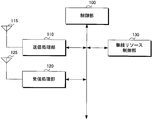
- FIG. 4 is a schematic block diagram illustrating a configuration of the base station apparatus 10 according to the present embodiment.
- the base station apparatus 10 includes a control unit 100 (base station side control unit) including a transmission processing unit 110, a reception processing unit 120, and a radio resource control unit 130.
- a transmission antenna 115 is connected to the transmission processing unit 110, and a reception antenna 125 is connected to the reception processing unit 120.
- the control unit 100 controls the radio resource allocation / modulation scheme / coding rate of the downlink shared data channel and the downlink control channel to the transmission processing unit 110. Against. Further, the control unit 100 generates control data to be transmitted using the downlink control channel based on the radio resource control information, and outputs the control data to the transmission processing unit 110.
- control unit 100 controls radio resource allocation, transmission power, modulation scheme, and coding rate of the uplink shared data channel and the uplink control channel based on the radio resource control information input from the radio resource control unit 130. This is performed for the reception processing unit 120.
- control unit 100 outputs the uplink channel quality input from the reception processing unit 120 to the radio resource control unit 130.
- control unit 100 generates control data to be transmitted using the downlink control channel based on the radio resource control information input from the radio resource control unit 130 and outputs the control data to the transmission processing unit 110.
- control unit 100 transmits a signal in each uplink element frequency band to the mobile station apparatus 20 that allocates radio resources of the uplink shared data channel to a plurality of uplink element frequency bands using a common transmission antenna. Between the first transmission mode for transmitting the signal and the second transmission mode for transmitting the signal of each element frequency band using a different transmission antenna, and information on the selected transmission mode is transmitted to the transmission processing unit 110. Output to.
- the control unit 100 determines the transmission mode based on the information regarding the transmission power remaining capacity for each of the plurality of power amplifiers notified from the mobile station apparatus 20 and the average transmission power of the plurality of uplink element frequency bands set in the mobile station apparatus 20. select.
- the transmission processing unit 110 generates a signal to be transmitted using the downlink control channel and the downlink shared data channel based on the control signal input from the control unit 100, and transmits the signal through the transmission antenna 115.
- the transmission processing unit 110 transmits the information data input from the higher layer and the information regarding the transmission mode input from the control unit 100 using the downlink shared data channel, and the control data input from the control unit 100 is downlinked. Transmit using the control channel.
- the reception processing unit 120 detects, demodulates, decodes, and controls reception signals of the uplink control channel and the uplink shared data channel received from the mobile station apparatus 20 by the reception antenna 125 according to the instruction of the control unit 100. Extract data and information data.
- the reception processing unit 120 outputs the extracted control data to the control unit 100 and outputs information data to the upper layer. Also, the reception processing unit 120 outputs control information included in the information data extracted from the uplink shared data channel to the control unit 100. For example, the reception processing unit 120 outputs to the control unit 100 information related to transmission power reserve (referred to as Power headroom) for each of the plurality of power amplifiers notified from the mobile station apparatus.
- Power headroom transmission power reserve
- the reception processing unit 120 measures the uplink channel quality (hereinafter referred to as uplink channel quality) of the mobile station apparatus 20 based on the received uplink reference signal, and the measured uplink channel quality is controlled by the control unit. 100 to the radio resource control unit 130. Details of the reception processing unit 120 will be described later.
- the radio resource control unit 130 transmits the transmission power of each mobile station device 20, intermittent transmission / reception cycle, radio resource allocation of the downlink control channel, radio resource allocation of the uplink control channel, radio resource allocation of the downlink shared data channel, uplink Radio resource allocation for shared data channels, modulation schemes / coding rates of various channels, transmission power control values for each uplink element frequency band, and the like are set, and radio resource control information is output to the control unit 100. Part of the radio resource control information is transmitted to the mobile station apparatus 20 through the transmission processing unit 110 based on an instruction from the control unit 100.
- the radio resource control unit 130 sets a transmission power control value based on the uplink channel quality input from the reception processing unit 120 through the control unit 100.
- the radio resource control unit 130 sets a transmission power control value for instructing to increase the transmission power.
- the radio resource control unit 130 A transmission power control value for instructing to decrease the transmission power is set, and when the uplink channel quality is approximately the same as the required quality, a transmission power control value for instructing to maintain the transmission power is set.
- FIG. 5 is a schematic block diagram illustrating a configuration of the transmission processing unit 110 of the base station apparatus 10 according to the present embodiment.
- the transmission processing unit includes a plurality of downlink shared data channel processing units 1100, a plurality of downlink control channel processing units 1110, a downlink pilot channel processing unit 1120, a multiplexing unit 1122, and an IFFT. (Inverse Fastier Transform) unit 1124, GI (Guard Interval) insertion unit 1126, D / A (Digital / Analog) unit 1128, and transmission RF (Radio Frequency) Frequency) unit 1130 (base station side transmission unit), and the transmission antenna 115 is connected to the transmission RF unit 1130.
- IFFT Inverse Fastier Transform
- each downlink shared data channel processing unit 1100 and each downlink control channel processing unit 1110 have the same configuration and function, only one of them will be described as a representative.
- downlink shared data channel processing section 1100 includes turbo coding section 1102 and data modulation section 1104, and downlink control channel processing section 1110 includes convolution coding section 1112 and QPSK.
- a modulation unit 1114 is provided.
- the downlink shared data channel processing unit 1100 is a processing unit that performs baseband signal processing for transmitting information data to the mobile station apparatus 20 by the OFDM method.
- the turbo coding unit 1102 performs turbo coding for increasing the error tolerance of the data at the coding rate input from the control unit, and outputs the information data to the data modulation unit 1104.
- the data modulation unit 1104 uses the modulation data input from the control unit 100, for example, QPSK (Quadrature Phase Shift Keying), 16QAM (16Quadrature Amplitude Modulation), for the code data encoded by the turbo coding unit 1102 16-value quadrature amplitude modulation) and 64QAM (64 Quadrature Amplitude Modulation), and a modulation symbol signal sequence is generated.
- QPSK Quadratture Phase Shift Keying
- 16QAM 16Quadrature Amplitude Modulation
- 64QAM 64 Quadrature Amplitude Modulation
- the downlink control channel processing unit 1110 is a processing unit that performs baseband signal processing for transmitting control data input from the control unit in the OFDM scheme.
- the convolutional coding unit 1112 performs convolutional coding for increasing the error tolerance of the control data based on the coding rate input from the control unit 100.
- the control data is controlled in bit units.
- the convolutional coding unit 1112 also performs rate matching to adjust the number of output bits for the bits subjected to the convolutional coding processing based on the coding rate input from the control unit 100. Then, convolutional encoder 1112 outputs the encoded control data to QPSK modulator 1114.
- the QPSK modulation unit 1114 modulates the control data encoded by the convolutional encoding unit 1112 using the QPSK modulation method, and outputs the modulated modulation symbol signal sequence to the multiplexing unit 1122.
- the downlink pilot channel processing unit 1120 generates a downlink reference signal that is a known signal in the mobile station apparatus 20 and outputs the downlink reference signal to the multiplexing unit 1122.
- the multiplexing unit 1122 receives the signal input from the downlink pilot channel processing unit 1120, the signal input from each of the downlink shared data channel processing unit 1100, and the signal input from each of the downlink control channel processing unit 1110. In accordance with an instruction from the control unit 100, multiplexing is performed on the downlink radio frame.
- Radio resource control information related to radio resource allocation of the downlink shared data channel and radio resource allocation of the downlink control channel set by the radio resource control unit 130 is input to the control unit 100, and based on the radio resource control information, the control unit 100 controls the processing of the multiplexing unit 1122.
- the multiplexing unit 1122 performs multiplexing between the downlink shared data channel and the downlink control channel by time multiplexing as shown in FIG.
- the multiplexing unit 1122 performs multiplexing between the downlink pilot channel and other channels by time / frequency multiplexing.
- the multiplexing unit 1122 multiplexes downlink shared data channels addressed to each mobile station apparatus 20 in units of downlink resource blocks, and uses a plurality of downlink resource blocks for one mobile station apparatus 20 for downlink. Sometimes shared data channels are multiplexed. Also, the multiplexing unit 1122 performs multiplexing of the downlink control channel addressed to each mobile station apparatus 20 using a plurality of downlink resource elements that are dispersed in the same downlink element frequency band and are dispersed. Further, multiplexing section 1122 outputs the multiplexed signal to IFFT section 1124.
- the IFFT unit 1124 performs inverse fast Fourier transform on the signal multiplexed by the multiplexing unit 1122, performs OFDM modulation, and outputs the result to the GI insertion unit 1126.
- the GI insertion unit 1126 generates a baseband digital signal including symbols in the OFDM scheme by adding a guard interval to the signal modulated by the OFDM scheme by the IFFT unit 1124. As is well known, the guard interval is generated by duplicating a part of the head or tail of a symbol to be transmitted. Further, the GI insertion unit 1126 outputs the generated baseband digital signal to the D / A unit 1128.
- the D / A 1128 unit converts the baseband digital signal input from the GI insertion unit 1126 into an analog signal and outputs the analog signal to the transmission RF unit 1130.
- the transmission RF unit 1130 generates an in-phase component and a quadrature component of the intermediate frequency from the analog signal input from the D / A unit 1128, and removes an extra frequency component for the intermediate frequency band.
- the transmission RF unit 1130 converts (up-converts) the intermediate frequency signal into a high frequency signal, removes excess frequency components, power-amplifies the signal with a power amplifier, and transmits the signal via the transmission antenna 115. Transmit to the mobile station device 20.
- FIG. 6 is a schematic block diagram illustrating a configuration of the reception processing unit 120 of the base station apparatus 10 according to the present embodiment.
- the reception processing unit includes a reception RF unit 1202, an A / D (Analog / Digital) unit 1204, an element frequency band separation unit 1206, and a plurality of uplink component frequency bands.
- the reception processing unit 1210 for each uplink component frequency band includes a GI removal unit 1212, a symbol timing detection unit 1216, an FFT unit 1214, a subcarrier demapping unit 1220, and reception quality measurement.
- Unit 1230, propagation path estimation unit 1232, uplink shared data channel propagation path equalization unit 1240, uplink control channel propagation path equalization unit 1222, IDFT unit 1224, data demodulation unit 1226, , A turbo decoding unit 1228 and an uplink control channel detection unit 1242 are provided. Since each uplink element frequency band reception processing unit 1210 has the same configuration and function, one of them will be described as a representative.
- the reception RF unit 1202 appropriately amplifies the signal received by the reception antenna 125, converts it to an intermediate frequency (down-conversion), removes unnecessary frequency components, and amplifies the signal level so that the signal level is appropriately maintained. , And quadrature demodulation based on the in-phase and quadrature components of the received signal.
- Reception RF section 1202 outputs the quadrature demodulated analog signal to A / D section 1204.
- the A / D unit 1204 converts the analog signal quadrature demodulated by the reception RF unit 1202 into a digital signal, and outputs the converted digital signal to the element frequency band separation unit 1206.
- Element frequency band separation section 1206 separates the received signal for each uplink element frequency band of the uplink system bandwidth, and outputs the received signal to each uplink element frequency band reception processing section 1210.
- the reception processing unit 1210 for each uplink component frequency band performs demodulation and decoding of the uplink shared data channel and the uplink control channel in the uplink component frequency band, and detects and outputs information data and control data.
- the symbol timing detection unit 1216 detects the symbol timing based on the signal input from the element frequency band separation unit 1206, and outputs a control signal indicating the detected symbol boundary timing to the GI removal unit 1212. To do.
- the GI removal unit 1212 removes a portion corresponding to the guard interval from the signal input from the element frequency band separation unit 1206 based on the control signal from the symbol timing detection unit 1216 and converts the remaining portion of the signal to the FFT unit. To 1214.
- the FFT unit 1214 performs fast Fourier transform on the signal input from the GI removal unit 1212, performs demodulation of the DFT-Spread-OFDM scheme, and outputs the result to the subcarrier demapping unit. Note that the number of points in the FFT unit 1214 is equal to the number of points in the IFFT unit of the mobile station apparatus 20 described later.
- the subcarrier demapping unit 1220 based on the control signal input from the control unit 100, the signal demodulated by the FFT unit 1214, the uplink pilot channel signal, the uplink shared data channel signal, and the uplink control channel To separate the signal.
- the subcarrier demapping unit 1220 outputs the separated uplink pilot channel signal to the propagation path estimation unit 1232 and the reception quality measurement unit 1230, and outputs the separated uplink shared data channel signal to the uplink shared data channel.
- the separated uplink control channel signal is output to the uplink control channel propagation path equalizing unit 1240.
- the propagation path estimation unit 1232 estimates propagation path fluctuations using the uplink reference signal of the uplink pilot channel separated by the subcarrier demapping unit 1220 and a known signal.
- the propagation path estimation unit 1232 outputs the estimated propagation path estimation value to the propagation path equalization unit 1222 for the uplink shared data channel and the propagation path equalization unit 1240 for the uplink control channel.
- the reception quality measurement unit 1230 measures the reception quality using the uplink reference signal of the uplink pilot channel in units of uplink element frequency bands, and the uplink channel quality that is the measurement result of the reception quality of each uplink element frequency band Is output to the control unit 100.
- the propagation path equalization unit 1222 for the uplink shared data channel uses the propagation path estimation value input from the propagation path estimation unit 1232 as the amplitude and phase of the uplink shared data channel signal separated by the subcarrier demapping unit 1220. Equalize based on Here, equalization refers to a process for restoring the fluctuation of the propagation path received by the signal during wireless communication.
- the channel equalization unit 1222 for the uplink shared data channel outputs the equalized signal to the IDFT unit 1224.
- the IDFT unit 1224 performs inverse discrete Fourier transform on the signal input from the propagation path equalization unit 1222 for the uplink shared data channel, and outputs the result to the data demodulation unit 1226.
- the data demodulation unit 1226 demodulates the uplink shared data channel signal converted by the IDFT unit 1224 and outputs the demodulated uplink shared data channel signal to the turbo decoding unit 1228. This demodulation is demodulation corresponding to the modulation method used in the data modulation unit of the mobile station apparatus 20, and the modulation method is input from the control unit 100.
- the turbo decoding unit 1228 decodes information data from the uplink shared data channel signal input from the data demodulating unit 1226 and demodulated.
- the coding rate is input from the control unit 100.
- a channel equalization unit 1240 for the uplink control channel uses the amplitude and phase of the uplink control channel signal separated by the subcarrier demapping unit 1220 based on the channel estimation value input from the channel estimation unit 1232. Equalize.
- the uplink channel equalization unit 1240 for the uplink control channel outputs the equalized signal to the uplink control channel detection unit 1242.
- the uplink control channel detection unit 1242 detects, demodulates, decodes, and detects control data, the signal input from the uplink control channel propagation path equalization unit 1240 according to the type of the transmitted control data To do.
- the base station apparatus 10 knows in advance the type of control data transmitted by the mobile station apparatus 20.
- the uplink control channel detection unit 1242 outputs the detected control data to the control unit 100.
- the control unit 100 and the subcarrier demapping unit 1220 The demodulator 1226, turbo decoder 1228, propagation path estimator 1232, and uplink control channel detector 1242 are controlled.
- control unit 100 determines which uplink element frequency band the uplink shared data channel and uplink control channel transmitted by each mobile station apparatus 20 are based on the control data and radio resource control information transmitted to the mobile station apparatus 20. Know if it is located in the radio resource.
- FIG. 7 is a schematic block diagram showing the configuration of the mobile station apparatus 20 according to this embodiment.
- the mobile station apparatus 20 includes a control unit 200 including a reception processing unit 210 and a transmission processing unit 220.
- the transmission processing unit 220 is connected to transmission antennas 225-1, 225-2, and 225-3, and the reception processing unit 210 is connected to a reception antenna 215.
- the control unit 200 confirms the data that is transmitted using the downlink shared data channel and is input from the reception processing unit 210, outputs information data to the upper layer in the data, and performs radio resource control information in the data. Based on the above, the reception processing unit 210 and the transmission processing unit 220 are controlled. For example, the control unit 200 relates to the uplink control channel in the transmission processing unit 220 based on the information about the radio resource and the radio resource allocation period in each uplink element frequency band of the uplink control channel included in the radio resource control information. Control processing.
- control unit 200 controls the reception processing unit 210 and the transmission processing unit 220 based on the control data.
- the reception processing unit 210 detects the downlink control channel signal indicating the radio resource allocation of the uplink shared data channel
- the control unit 200 detects the uplink shared data channel of one or more uplink element frequency bands.
- Control data indicating radio resource allocation and control data indicating the transmission power control value of the uplink shared data channel are input from the reception processing unit 210.
- control unit 200 sets an upper limit value of average transmission power for the transmission processing unit 220.
- control unit 200 performs first transmission for transmitting a signal of each uplink element frequency band using a common transmission antenna based on information on the transmission mode transmitted using the downlink shared data channel.
- the transmission processing unit 220 is controlled by selecting one of a mode and a second transmission mode for transmitting a signal of each uplink component frequency band using a different transmission antenna.
- control unit 200 controls the output of the signals in each uplink element frequency band of the transmission processing unit 220 to the transmission antennas 225-1, 225-2, and 225-3.
- control unit 200 generates information on the channel quality indicator CQI and the received power of the downlink reference signal based on the downlink reception quality (hereinafter referred to as downlink channel quality) input from the reception processing unit 210.
- the transmission processing unit 220 is controlled to transmit the channel quality indicator CQI using the uplink control channel and information related to the received power of the downlink reference signal using the uplink shared data channel.
- control unit 200 measures transmission power reserves of a plurality of power amplifiers, generates information on transmission power reserves for each power amplifier, and transmits the information to the base station apparatus 10 using an uplink shared data channel.
- the processing unit 220 is controlled.
- the transmission power surplus is a value obtained by subtracting the average transmission power currently used for transmission from the upper limit value of power that can be handled by the power amplifier, and means the remaining transmission power that can be used for transmission. For example, the remaining transmission power is indicated by 1 dB unit information within the range of [40; -23 dB].
- the control unit 200 grasps this transmission power reserve for each of the plurality of power amplifiers, and controls the transmission processing unit 220 so as to transmit information on the transmission power reserve to the base station apparatus 10.
- the reception processing unit 210 receives a signal from the base station device 10 via the reception antenna 215, and demodulates and decodes the received signal in accordance with an instruction from the control unit 200.
- the reception processing unit 210 detects a downlink control channel signal addressed to itself, the reception processing unit 210 outputs control data obtained by decoding the downlink control channel signal to the control unit 200.
- the control data includes information such as a transmission power control value of the uplink shared data channel.
- the reception processing unit 210 decodes the downlink shared data channel addressed to itself based on the instruction of the control unit 200 after outputting the control data included in the downlink control channel to the control unit. Is output to the upper layer via the control unit 200. In addition, the reception processing unit 210 outputs to the control unit 200 radio resource control information obtained by decoding the downlink shared data channel and information related to the transmission mode. Further, the reception processing unit measures the reception quality using the downlink reference signal of the downlink pilot channel in each downlink element frequency band, and outputs the measurement result to the control unit 200. Details of the reception processing unit 210 will be described later.
- the transmission processing unit 220 encodes information data and control data according to an instruction from the control unit 200, sets a transmission power value of the modulated signal, and sends one signal of each uplink element frequency band to the base station apparatus 10. It transmits via the above transmission antennas. For example, the transmission processing unit 220 transmits a signal including information on the remaining transmission power for each of the plurality of power amplifiers.
- the control unit 200 selects the first transmission mode
- the transmission processing unit 220 outputs a signal in each uplink component frequency band to a common transmission antenna via a common power amplifier.
- the second transmission mode is selected, signals in each uplink element frequency band are output to different transmission antennas via different power amplifiers. Details of the transmission processing unit 220 will be described later.
- FIG. 8 is a schematic block diagram showing the configuration of the reception processing unit 210 of the mobile station apparatus 20 according to this embodiment.
- the reception processing unit 210 is connected to a reception antenna 215, and includes a reception RF unit 2102, an A / D unit 2104, a symbol timing detection unit 2114, a GI removal unit 2106, and an FFT unit.
- a demultiplexing unit 2110 a propagation channel estimation unit 2118, a reception quality measurement unit 2116, a downlink shared data channel propagation channel compensation unit 2112, a downlink shared data channel decoding unit 2130, and downlink control A channel propagation path compensation unit 2120 and a downlink control channel decoding unit 2140 are configured.
- the downlink shared data channel decoding unit 2130 includes a data demodulation unit 2132 and a turbo decoding unit 2134
- the downlink control channel decoding unit 2140 includes a QPSK demodulation unit 2142, And a Viterbi decoder unit 2144.
- the reception RF unit 2102 appropriately amplifies the signal received by the reception antenna 215, converts it to an intermediate frequency (down-conversion), removes unnecessary frequency components, and amplifies the signal so that the signal level is appropriately maintained. , And quadrature demodulation based on the in-phase and quadrature components of the received signal.
- Reception RF section 2102 outputs the quadrature demodulated analog signal to A / D section 2104.
- the A / D unit 2104 converts the analog signal quadrature demodulated by the reception RF unit 2102 into a digital signal, and outputs the converted digital signal to the symbol timing detection unit 2114 and the GI removal unit 2106.
- Symbol timing detection section 2114 detects the timing of the OFDM symbol based on the digital signal converted by A / D section 2104 and outputs a control signal indicating the detected symbol boundary timing to GI removal section 2106.
- GI removal section 2106 removes a portion corresponding to the guard interval from the digital signal output from A / D section 2104 based on the control signal from symbol timing detection section 2114, and converts the remaining portion of the signal to FFT section 2108. Output to. FFT section 2108 performs fast Fourier transform on the signal input from GI removal section 2106, performs OFDM demodulation, and outputs the result to demultiplexing section 2110.
- the demultiplexing unit 2110 demultiplexes the signal demodulated by the FFT unit 2108 into a downlink control channel signal and a downlink shared data channel signal based on the control signal input from the control unit 200.
- the demultiplexing unit 2110 outputs the separated downlink shared data channel signal to the downlink shared data channel propagation path compensating unit 2112, and outputs the separated downlink control channel signal for the downlink control channel To the propagation path compensation unit 2120.
- demultiplexing section 2110 demultiplexes the downlink resource element in which the downlink pilot channel is arranged, and outputs the downlink reference signal of the downlink pilot channel to propagation path estimation section 2118 and reception quality measurement section 2116.
- the propagation path estimation unit 2118 estimates the propagation path variation using the downlink reference signal and the known signal of the downlink pilot channel separated by the demultiplexing unit 2110, and compensates for the propagation path variation.
- the channel compensation value for adjusting the phase are output to the channel compensation unit 2112 for the downlink shared data channel and the channel compensation unit 2120 for the downlink control channel.
- the reception quality measurement unit 2116 measures the downlink channel quality using the downlink reference signal of the downlink pilot channel, and outputs the measurement result to the control unit 200.
- the propagation path compensation unit 2112 for the downlink shared data channel determines the amplitude and phase of the downlink shared data channel signal separated by the demultiplexing unit according to the propagation path compensation value input from the propagation path estimation unit 2118. Adjust every time.
- the propagation path compensation unit 2112 for the downlink shared data channel outputs the signal whose propagation path has been adjusted to the data demodulation unit 2132 of the downlink shared data channel decoding unit 2130.
- the downlink shared data channel decoding unit 2130 is a processing unit that demodulates and decodes the downlink shared data channel and detects information data based on an instruction from the control unit 200.
- Data demodulation section 2132 demodulates the downlink shared data channel signal input from propagation path compensation section 2112 and outputs the demodulated downlink shared data channel signal to the turbo decoding section. This demodulation is a demodulation corresponding to the modulation method used in the data modulation unit of the base station apparatus 10.
- the turbo decoding unit 2134 decodes information data from the demodulated downlink shared data channel signal input from the data demodulation unit 2132 and outputs it to the upper layer via the control unit 200. Radio resource control information transmitted using the downlink shared data channel and information related to the transmission mode are also output to the control unit 200.
- the downlink control channel propagation path compensation unit 2120 adjusts the amplitude and phase of the downlink control channel signal separated by the demultiplexing unit 2110 according to the propagation path compensation value input from the propagation path estimation unit 2118.
- the downlink control channel propagation path compensation unit 2120 outputs the adjusted signal to the QPSK demodulation unit 2142 of the downlink control channel decoding unit 2140.
- the downlink control channel decoding unit 2140 is a processing unit that demodulates and decodes the signal input from the propagation path compensation unit 2120 and detects control data as follows.
- the QPSK demodulator 2142 performs QPSK demodulation on the downlink control channel signal and outputs the result to the Viterbi decoder 2144.
- the Viterbi decoder unit 2144 decodes the signal demodulated by the QPSK demodulation unit 2142 and outputs the decoded control data to the control unit 200.
- this signal is expressed in bit units, and the Viterbi decoder unit 2144 also performs rate dematching to adjust the number of bits to be subjected to Viterbi decoding processing on the input bits.
- the control unit 200 determines whether the control data input from the Viterbi decoder unit 2144 is error-free control data addressed to the own device. If the control unit 200 determines that the control data is addressed to the own device without error, based on the control data.
- the demultiplexer, data demodulator, turbo decoder, and transmission processor are controlled.
- the control unit 200 inputs the information data to the transmission processing unit for each uplink element frequency band of the transmission processing unit 220 described later, and transmits Control power.
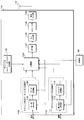
- FIG. 9 is a schematic block diagram showing the configuration of the transmission processing unit 220 of the mobile station apparatus 20 according to this embodiment.
- the transmission processing unit 220 includes a plurality of uplink element frequency band transmission processing units 2200 and a plurality of transmission units 2226, and includes three transmission antennas 225-1, 225-2, 225-3 is connected.
- the transmission processing unit 2200 for each uplink component frequency band includes a turbo coding unit 2202, a data modulation unit 2204, a DFT unit 2206, an uplink pilot channel processing unit 2208, and uplink control.
- a channel processing unit 2210, a subcarrier mapping unit 2212, an IFFT unit 2214, a GI insertion unit 2216, and a transmission power control unit 2218 are included.
- the mobile station apparatus 20 includes a transmission processing unit 2200 for each uplink element frequency band corresponding to the number of uplink element frequency bands that can be handled.
- the transmission unit 2226 includes an element frequency band synthesis unit 2220, a D / A unit 2222, and a transmission RF unit 2224.
- the mobile station apparatus 20 has as many transmission units 2226 as the number of transmission antennas.
- a case where three transmitting units 2226 are configured in the mobile station device 20 will be described.
- each uplink component frequency band transmission processing unit 2200 and each transmission unit 2226 have the same configuration and function, and therefore each of them will be described as a representative.
- the transmission processing unit 2200 for each uplink element frequency band performs encoding, modulation, and transmission power settings for information data and control data, and sets up an uplink shared data channel and an uplink control channel in the uplink element frequency band. It is a processing unit that generates a signal to be transmitted. Further, the transmission processing unit 2200 for each uplink element frequency band outputs the generated signal to the transmission unit 2226 based on an instruction from the control unit 200.
- the mobile station apparatus 20 of the present invention is not limited to the number of transmission antennas and the number of transmission units used here.
- the present invention may be composed of four transmission antennas and four transmission units.
- the turbo coding unit 2202 performs turbo coding for increasing the error tolerance of the data at the coding rate instructed by the control unit 200, and outputs the information data to the data modulation unit 2204.
- the data modulation unit 2204 modulates the code data encoded by the turbo coding unit 2202 using a modulation method instructed by the control unit 200, for example, a modulation method such as QPSK, 16QAM, or 64QAM, and converts the modulation symbol signal sequence. Generate.
- Data modulation section 2204 outputs the generated modulation symbol signal sequence to DFT section 2206.
- the DFT unit 2206 performs discrete Fourier transform on the signal output from the data modulation unit 2204, and outputs the result to the subcarrier mapping unit 2212.
- the uplink control channel processing unit 2210 performs baseband signal processing for transmitting control data input from the control unit 200.
- the control data input to the uplink control channel processing unit 2210 is any one of the downlink channel quality indicator CQI, the reception response ACK / NACK, and the scheduling request SR.
- the uplink control channel processing unit 2210 generates a signal of a different format according to the type of control data to be processed, and outputs it to the subcarrier mapping unit.
- the type of control data to be processed is input from the control unit 200 to the uplink control channel processing unit 2210.
- Uplink pilot channel processing section 2208 generates an uplink reference signal that is a known signal in base station apparatus 10 and outputs the uplink reference signal to subcarrier mapping section 2212.
- the subcarrier mapping unit 2212 receives the signal input from the uplink pilot channel processing unit 2208, the signal input from the DFT unit 2206, and the signal input from the uplink control channel processing unit from the control unit 200. According to the instruction, it is arranged on the subcarrier and output to IFFT section 2214.
- the subcarrier mapping unit 2212 relates to the arrangement of uplink pilot channel signals in the uplink shared data channel and the arrangement of uplink pilot channel signals in the uplink control channel. Arrange in time multiplexed and output.
- the IFFT 2214 unit performs inverse fast Fourier transform on the signal output from the subcarrier mapping unit, and outputs the result to the GI insertion unit 2216.
- the number of points in the IFFT unit 2214 is larger than the number of points in the DFT unit 2206.
- the mobile station apparatus 20 uses the DFT unit 2206, the subcarrier mapping unit 2212, and the IFFT unit 2214 to perform DFT-Spread-OFDM modulation on the signal transmitted using the uplink shared data channel.
- GI insertion section 2216 adds a guard interval to the signal input from IFFT section 2214 and outputs the signal with the guard interval added to transmission power control section 2218.
- the transmission power control unit 2218 controls the average transmission power of the signal input from the GI insertion unit 2216 based on the control signal from the control unit 200 and outputs the signal to the element frequency band synthesis unit 2220 of the transmission unit 2226. .
- the transmission power control unit 2218 controls the average transmission power so as to be within the upper limit value of the average transmission power set by the control unit 200. Specifically, the transmission power control unit 2218 is assigned to the path loss measured by the mobile station device 20, the transmission power control value notified from the base station device 10 to the mobile station device 20, and the uplink shared data channel.
- the mobile station apparatus 20 is notified of the number of uplink resource block pairs, the modulation scheme-dependent power offset value based on the modulation scheme applied to the uplink shared data channel, and the downlink shared data channel at the time of communication connection. And a coefficient for multiplying the path loss measured by the mobile station device 20 that is broadcasted to the mobile station device 20 in the communication area of the base station device 10 using the downlink shared data channel. Accordingly, a temporary average transmission power value is set, and an upper limit value of the average transmission power of the uplink element frequency band input from the control unit 200 Comparing the average transmit power value is set to the average transmission power value actually used a low value.
- the transmission power control unit 2218 sets the average transmission power using the following equation.
- min ⁇ A, B ⁇ indicates that A and B are compared and a smaller value is selected.
- the path loss is calculated based on RSRP (Reference Signal Received Power) measured from the downlink reference signal received by the mobile station device 20 from the base station device.
- RSRP Reference Signal Received Power
- the number of uplink resource block pairs allocated to the uplink shared data channel is calculated from the radio resources of the uplink shared data channel configured as the downlink control channel.
- the modulation scheme-dependent power offset value based on the modulation scheme applied to the uplink shared data channel is defined in advance by the communication system.
- the uplink element frequency band transmission processing unit 2200 outputs a signal to the transmission unit 2226 corresponding to each of the transmission antennas 225-1, 225-2, and 225-3 based on the control signal from the control unit 200. Details will be described later.
- Element frequency band synthesizer 2220 synthesizes the signal for each uplink element frequency band input from transmission element for each uplink element frequency band 2200 and outputs the synthesized signal to D / A section 2222. More specifically, the element frequency band synthesizer 2220 converts the signal for each uplink element frequency band input from the transmission element for each uplink element frequency band 2200 into a signal having a suitable frequency.
- the D / A 2222 unit converts the baseband digital signal input from the element frequency band synthesis unit 2220 into an analog signal and outputs the analog signal to the transmission RF unit 2224.
- the transmission RF unit 2224 generates an in-phase component and a quadrature component of the intermediate frequency from the analog signal input from the D / A unit 2222 and removes an extra frequency component for the intermediate frequency band.
- the transmission RF unit converts (up-converts) the intermediate frequency signal into a high frequency signal, removes excess frequency components, amplifies the power using the power amplifier in the transmission RF unit, and transmits the transmission antenna 225-
- the data is transmitted to the base station apparatus 10 via 1, 252-2, 225-3.
- the transmission unit 2226 stops internal processing when no signal is input from the transmission processing unit 2200 for each uplink element frequency band. Alternatively, some of the transmission units 2226 are notified in advance from the control unit 200 that no signal is input from the transmission processing unit 2200 for each uplink element frequency band, that is, input a control signal for stopping internal processing from the control unit 200 in advance. The internal processing is stopped.
- FIG. 10 is a diagram illustrating an information field of control data of a downlink control channel indicating radio resource allocation of the uplink shared data channel.
- the information field of the control data of the downlink control channel indicating the radio resource allocation of the uplink shared data channel includes “radio resource allocation information” indicating the position of the uplink resource block pair to be allocated within one uplink element frequency band, “Modulation scheme / coding rate”, “Retransmission parameter” indicating a redundant version number and new data indicator, “Transmission power control value”, Cyclic redundancy check CRC: Cyclic Redundancy Check generated from control data, It is configured to include an information field of “CRC + mobile station identifier” configured by the result of the logical operation of the mobile station identifier. Other information fields may be configured in the control data.
- the base station apparatus 10 transmits a downlink control channel including control data shown in FIG. 10 to the mobile station apparatus 20 for each uplink element frequency band to which radio resources are allocated. For example, when the base station apparatus 10 allocates uplink shared data channel radio resources to three uplink component frequency bands, the base station apparatus 10 includes control data indicating radio resource allocation of the uplink shared data channel.
- the downlink control channels are transmitted to the mobile station apparatus 20.
- FIG. 11 is a diagram for explaining the correspondence between the downlink element frequency band and the uplink element frequency band.
- there are three downlink element frequency bands first downlink element frequency band, second downlink element frequency band, and third downlink element frequency band
- uplink element frequency bands first uplink element frequency band
- the downlink element frequency band and the uplink element frequency band have a one-to-one correspondence.
- the first downlink element frequency band is the first uplink element frequency band
- the second downlink element frequency band is the second uplink element frequency band
- the third downlink element frequency band is the third Corresponds to the uplink component frequency band.
- the radio resource allocation of the uplink shared data channel of the downlink control channel arranged in the first downlink element frequency band indicates the radio resource allocation of the uplink shared data channel of the first uplink element frequency band.
- Radio resource allocation of the uplink shared data channel of the downlink control channel arranged in the second downlink element frequency band indicates radio resource allocation of the uplink shared data channel of the second uplink element frequency band;
- the radio resource allocation of the uplink shared data channel of the downlink control channel arranged in the third downlink element frequency band indicates the radio resource allocation of the uplink shared data channel of the third uplink element frequency band.
- 12A to 12C are diagrams for explaining the relationship between signals in the uplink element frequency band and transmission antennas in each transmission mode (first transmission mode and second transmission mode).
- there are three uplink element frequency bands first uplink element frequency band, second uplink element frequency band, and third uplink element frequency band
- transmission antennas first transmission antenna, first A case where there are three transmission antennas and three transmission antennas will be described.
- the first transmission mode is a transmission mode in which the mobile station device 20 transmits a signal of each uplink element frequency band using a common transmission antenna
- the second transmission mode is a mode in which the mobile station device 20 transmits each uplink. This is a transmission mode in which signals in element frequency bands are transmitted using different transmission antennas.
- FIG. 12A is a diagram for explaining a relationship between a signal in an uplink element frequency band and a transmission antenna in the first transmission mode.
- the mobile station apparatus 20 transmits a signal in the first uplink element frequency band using the first transmission antenna, transmits a signal in the second uplink element frequency band using the first transmission antenna, A signal in the third uplink element frequency band is transmitted using the first transmission antenna. That is, the mobile station apparatus 20 transmits signals of the respective uplink element frequency bands (first uplink element frequency band, second uplink element frequency band, and third uplink element frequency band) to a common transmission antenna (first antenna). 1 transmission antenna).
- control unit 200 outputs a control signal to each processing unit, and the transmission power control unit 2218 in the transmission processing unit 2200 for each uplink component frequency band is used for the first uplink component frequency band and the second uplink component frequency band.
- Signals in the link element frequency band and the third uplink element frequency band are output to one transmission unit 2226, for example, the transmission unit 2226 corresponding to the transmission antenna 225-1.
- the transmission unit 2226 combines the signals from the transmission processing units 2200 for each of the three uplink component frequency bands in the element frequency band combining unit 2220, amplifies the power, and outputs the result to the transmission antenna 225-1.
- FIG. 12B is a diagram for explaining the relationship between the uplink element frequency band signal and the transmission antenna in the second transmission mode.
- the mobile station apparatus 20 transmits a signal in the first uplink element frequency band using the first transmission antenna, transmits a signal in the second uplink element frequency band using the second transmission antenna, A signal in the third uplink element frequency band is transmitted using the third transmission antenna. That is, the mobile station apparatus 20 transmits signals of the respective uplink element frequency bands (first uplink element frequency band, second uplink element frequency band, and third uplink element frequency band) to different transmission antennas (first Transmission antenna, second transmission antenna, and third transmission antenna).
- control unit 200 outputs a control signal to each processing unit, and the transmission power control unit 2218 in the transmission processing unit 2200 for each uplink component frequency band is used for the first uplink component frequency band and the second uplink component frequency band.
- the signals in the link element frequency band and the third uplink element frequency band are output to different transmission units 2226, in other words, to the transmission units 2226 respectively corresponding to the transmission antennas 225-1, 225-2, and 225-3.
- Each transmission unit 2226 processes a signal from one uplink component frequency band transmission processing unit 2200 in the element frequency band synthesis unit 2220, amplifies the power, and transmits it to the transmission antennas 225-1, 225-2, and 225-3. Output.
- FIG. 12C is a diagram for explaining a relationship between a signal in an uplink element frequency band and a transmission antenna in a transmission mode in which the first transmission mode and the second transmission mode are used together.
- the mobile station apparatus 20 transmits a signal in the first uplink element frequency band using the first transmission antenna, transmits a signal in the second uplink element frequency band using the first transmission antenna, A signal in the third uplink element frequency band is transmitted using the second transmission antenna. That is, the mobile station apparatus 20 uses a common transmission antenna (first transmission antenna) for signals in a plurality of uplink element frequency bands (first uplink element frequency band, second uplink element frequency band). Transmitted signals of a plurality of uplink element frequency bands (first uplink element frequency band and third uplink element frequency band, or second uplink element frequency band and third uplink element frequency band) Are transmitted using different transmission antennas (a first transmission antenna and a second transmission antenna).
- control unit 200 outputs a control signal to each processing unit, and the transmission power control unit 2218 in the transmission processing unit 2200 for each uplink component frequency band is used for the first uplink component frequency band and the second uplink component frequency band.
- the signal of the link element frequency band is output to a common transmission unit 2226, for example, the transmission unit 2226 corresponding to the transmission antenna 225-1, and the transmission power control unit 2218 in the transmission processing unit 2200 for each uplink component frequency band is the first.
- the uplink element frequency band and the third uplink element frequency band (or the second uplink element frequency band and the third uplink element frequency band) of the transmission element 2226 for example, the transmission antenna 225-1
- the data is output to the transmission unit 2226 corresponding to each of 225-2.
- Each transmission unit 2226 combines signals from two uplink component frequency band transmission processing units 2200 in the element frequency band synthesis unit 2220 or processes signals from one uplink component frequency band transmission processing unit 2200.
- the power is amplified and output to the transmitting antennas 225-1 and 225-2.
- the control unit 100 selects a transmission mode based on the average transmission power of the mobile station apparatus 20 in each uplink element frequency band to which radio resources are allocated.
- the base station apparatus 10 is notified by the mobile station apparatus 20 of information regarding transmission power reserve (Power headroom) related to the performance of each power amplifier of the mobile station apparatus 20 as a parameter regarding transmission power.
- transmission power reserve Power headroom
- the control unit 100 refers to the transmission power remaining capacity of each power amplifier, which is a parameter related to transmission power notified from the mobile station apparatus 20, and when there is remaining power in the transmission power of one power amplifier, A first transmission mode is selected in which a signal in each uplink element frequency band is transmitted using a common transmission antenna using the transmission RF unit 2224) of the transmission unit 2226. In other words, when the sum of the average transmission powers of a plurality of uplink element frequency bands has a margin compared to the maximum power that can be handled by one power amplifier, or when the maximum power is not exceeded, the control unit 100 The first transmission mode is selected.
- the control unit 100 refers to the transmission power surplus for each power amplifier notified from the mobile station device 20, and when there is no surplus power in the transmission power of one power amplifier, each uplink element frequency is determined using a plurality of power amplifiers.
- a second transmission mode is selected in which signals in the band are transmitted using different transmission antennas. In other words, the control unit 100 determines whether the sum of the average transmission powers of a plurality of uplink element frequency bands has no margin compared to the maximum power that can be handled by one power amplifier or exceeds the maximum power. Select the second transmission mode.
- the control unit 100 determines whether or not there is a margin in the power amplifier in consideration of the value of the average transmission power set in units of uplink subframes with respect to the transmission power remaining capacity notified from the mobile station apparatus 20.
- having a margin means that the sum of the average transmission powers of a plurality of uplink element frequency bands is smaller by a predetermined value than the maximum power that can be handled by the power amplifier. This is because the open-loop transmission power control method and the closed-loop transmission power control method are used as the transmission power control method of the mobile station apparatus 20, and therefore the average transmission power value estimated by the base station apparatus 10 and the mobile station apparatus 20 are actually This is to cope with an error in the value of the average transmission power set to.
- the control unit 100 sets the number of transmission antennas and transmission units used by the mobile station device 20 as small as possible in order to reduce the power consumption of the mobile station device 20.
- the first transmission mode for transmitting a signal of each uplink element frequency band using a common transmission antenna according to the average transmission power of a plurality of uplink element frequency bands, and each element It is possible to switch the second transmission mode for transmitting a signal in the frequency band using a different transmission antenna, and to reduce power consumption by operating as few power amplifiers as possible while Communication quality suitable for signals in the uplink component frequency band of can be realized.
- the base station apparatus 10 selects the transmission mode based on the transmission power remaining capacity of the plurality of power amplifiers and the average transmission power of the plurality of uplink element frequency bands has been described.
- the transmission mode may be selected based on only the transmission power remaining capacity of the amplifier.
- the base station device 10 selects a second transmission mode for transmitting signals in a plurality of uplink component frequency bands using a plurality of power amplifiers and a plurality of transmission antennas when the remaining transmission power of one power amplifier is small. Selecting a first transmission mode for transmitting signals in a plurality of uplink element frequency bands using a single power amplifier and a single transmission antenna when there is a large amount of remaining transmission power of one power amplifier. It may be.
- the base station apparatus 10 may select a transmission mode based on several transmission parameters such as transmission power reserve and uplink channel quality, transmission power reserve and uplink shared data channel data amount. .
- the base station apparatus 10 has poor uplink channel quality with respect to the remaining transmission power that can be transmitted by the mobile station apparatus 20 indicated by the remaining transmission power, and the mobile station apparatus 20 has a single power amplifier
- the second transmission mode is selected when the transmission antenna is insufficient to transmit signals in a plurality of uplink component frequency bands, and the uplink channel quality with respect to the remaining transmission power that can be transmitted by the mobile station apparatus 20
- the first transmission mode is selected when the mobile station apparatus 20 is sufficient to transmit signals of a plurality of uplink element frequency bands with a single power amplifier and a single transmission antenna.
- the base station apparatus 10 has a large amount of data to be transmitted with respect to the remaining transmission power that can be transmitted by the mobile station apparatus 20 indicated by the transmission power reserve capacity, and requires more transmission power.
- Select a second transmission mode when a single power amplifier and a single transmission antenna are insufficient to transmit signals in a plurality of uplink component frequency bands, and the remaining transmittable signal of the mobile station apparatus 20
- the amount of data to be transmitted is not large with respect to the transmission power of the mobile station, and no more transmission power is required.
- the mobile station apparatus 20 has a single power amplifier, a single transmission antenna, and a plurality of uplink element frequency bands. The first transmission mode is selected when sufficient to transmit a signal.
- the base station apparatus 10 may select the transmission mode based on the path loss instead of the transmission power remaining capacity.
- the base station apparatus 10 selects the second transmission mode when the path loss of the mobile station apparatus 20 is larger than a predetermined value, and selects the first transmission mode when the path loss of the mobile station apparatus 20 is smaller than a predetermined value.
- the mobile station device 20 at the cell edge basically transmits signals in a plurality of uplink element frequency bands in the second transmission mode using a plurality of transmission antennas
- the mobile station apparatus 20 has a plurality of uplink element frequency bands in the second transmission mode using a small number of transmission antennas or the first transmission mode using a single transmission antenna with respect to the mobile station apparatus 20 at the cell edge.
- a signal will be transmitted.
- a change in the transmission mode is reduced with respect to fluctuations in the number of uplink component frequency bands used for the uplink shared data channel, and a stable communication system can be constructed.
- the mobile station apparatus 20 performs different transmission power control based on the transmission mode. More specifically, when the control unit 200 selects the first transmission mode, the transmission power control unit 2218 selects the upper limit value of the average transmission power in the uplink element frequency band, and the control unit 200 selects the second transmission mode. Set to a smaller value compared to the case.
- the transmission power control unit 2218 sets a smaller value as the upper limit value of the average transmission power in the uplink element frequency band as the number of uplink element frequencies simultaneously used for signal transmission increases. May be.
- the input value to the power amplifier in the transmission RF unit can be set to an appropriate value.
- the signal in the uplink element frequency band is a DFT-S-OFDM single carrier signal.
- the signal in the uplink element frequency band is a NxDFT-S-OFDM multicarrier signal.
- the NxDFT-S-OFDM multicarrier signal has an increased PAPR (Peak-to-Average Power Ratio) compared to the DFT-S-OFDM single carrier signal.
- PAPR Peak-to-Average Power Ratio
- the transmission power control unit 2218 sets the upper limit value of the average transmission power of the uplink element frequency band to a different value based on the transmission mode selected by the control unit 200.
- the upper limit value of the average transmission power of the uplink component frequency band is set to a smaller value, thereby making the first transmission
- the transmission signal becomes a multicarrier signal
- the PAPR of the transmission power increases
- the dynamic range of the transmission power increases
- the input value to the power amplifier in the transmission RF section is the power amplifier capability. It is possible to reduce the situation that exceeds.
- the transmission power control unit 2218 sets a smaller value as the upper limit value of the average transmission power in the uplink element frequency band as the number of uplink element frequencies simultaneously used for signal transmission increases. By doing so, it is possible to appropriately control the input value to the power amplifier within the capability of the power amplifier in consideration of the variation of the PAPR of the transmission power that changes as the number of uplink element frequency bands used simultaneously increases. .
- the base station apparatus 10 applies scrambling to the cyclic redundancy check configured in the downlink control channel, and actually places the logical operation result of the cyclic redundancy check and mobile station identifier on which the scrambling is performed in the downlink control channel. To send.
- a scrambling code unique to the transmission antenna of the mobile station apparatus 20 is used for scrambling.
- the base station apparatus 10 applies to each of the downlink control channels including the radio resource allocation information of the uplink shared data channel of each uplink element frequency band. Apply a common scrambling code.
- the base station device 10 applies to each of the downlink control channels including the radio resource allocation information of the uplink shared data channel of each uplink element frequency band. Apply different scrambling codes.
- the mobile station device 20 recognizes in advance a set of scrambling codes applied to its own mobile station device.
- the mobile station apparatus 20 detects a downlink control channel addressed to the mobile station apparatus.
- the mobile station apparatus 20 detects a downlink control channel including radio resource allocation information of uplink shared data channels of a plurality of uplink component frequency bands, and a common scrambling code is applied to each downlink control channel If the first transmission mode is selected and signals in each uplink element frequency band are transmitted using a common transmission antenna, and a different scrambling code is applied to each downlink control channel, the second A transmission mode is selected, and signals in each uplink element frequency band are transmitted using different transmission antennas.
- the reception processing unit 210 of the mobile station device 20 detects the downlink control channel addressed to the mobile station device, the reception processing unit 210 also outputs information related to the scrambling code applied together with the control data to the control unit 200.
- the control unit 200 performs the transmission antenna mode selection process based on the scrambling code input from the reception processing unit 210.
- the base station apparatus 10 has shown the case where the transmission mode is selected based on the transmission power surplus notified from the mobile station apparatus 20 and the average transmission power set by the mobile station apparatus 20,
- the mobile station device 20 may select the transmission mode.
- the control unit 200 of the mobile station apparatus 20 manages and grasps the transmission power remaining capacity of the power amplifier in the transmission RF unit 2224 of each transmission unit 2226.
- the control unit 200 selects a transmission mode based on the average transmission power in each uplink element frequency band controlled by the transmission power control unit 2218 and the transmission power remaining capacity.
- the details of the transmission mode selection method of the control unit 200 are the same as the transmission mode selection method in the base station apparatus 10 described above.
- the downlink component frequency band and the uplink component frequency band correspond one-to-one
- the downlink control channel including the radio resource allocation of the uplink shared data channel arranged in the downlink component frequency band is shown.
- other configurations may be used.
- a configuration in which the number of the uplink component frequency band corresponding to the downlink control channel is included and the downlink control channel including the radio resource allocation of the uplink shared data channel can be arranged in any downlink component frequency band Good.
- the program that operates in the mobile station apparatus related to the present invention is a program (a program that causes a computer to function) that controls the CPU and the like so as to realize the functions of the above-described embodiments related to the present invention.
- Information handled by these devices is temporarily stored in the RAM at the time of processing, then stored in various ROMs and HDDs, read out by the CPU, and corrected and written as necessary.
- a semiconductor medium for example, ROM, nonvolatile memory card, etc.
- an optical recording medium for example, DVD, MO, MD, CD, BD, etc.
- a magnetic recording medium for example, magnetic tape, Any of a flexible disk etc.
- the program when distributing to the market, can be stored and distributed on a portable recording medium, or transferred to a server computer connected via a network such as the Internet.
- a server computer connected via a network such as the Internet.
- the storage device of the server computer is also included in the present invention.
- Radio communication system 10 Base station apparatus 20-1, 20-2, 20-3 Mobile station apparatus 100, 200 Control unit 110, 220 Transmission processing unit 115 Transmission antenna 210 Reception processing unit 2226 Transmission unit
Landscapes
- Engineering & Computer Science (AREA)
- Computer Networks & Wireless Communication (AREA)
- Signal Processing (AREA)
- Mobile Radio Communication Systems (AREA)
- Radio Transmission System (AREA)
Abstract
Priority Applications (5)
| Application Number | Priority Date | Filing Date | Title |
|---|---|---|---|
| US13/378,677 US8873485B2 (en) | 2009-06-17 | 2010-04-23 | Mobile station apparatus, base station apparatus, communication system, communication method and control program |
| JP2011519675A JP5377639B2 (ja) | 2009-06-17 | 2010-04-23 | 移動局装置、基地局装置、通信システム、通信方法および制御プログラム |
| EP10789315A EP2445278A1 (fr) | 2009-06-17 | 2010-04-23 | Dispositif de station mobile, dispositif de station de base, système de communication, procédé de communication et programme de commande |
| CN201080026104XA CN102804874A (zh) | 2009-06-17 | 2010-04-23 | 移动站装置、基站装置、通信系统、通信方法和控制程序 |
| EA201270029A EA201270029A1 (ru) | 2009-06-17 | 2010-04-23 | Устройство мобильной станции, устройство базовой станции, система связи, способ связи и управляющая программа |
Applications Claiming Priority (2)
| Application Number | Priority Date | Filing Date | Title |
|---|---|---|---|
| JP2009144704 | 2009-06-17 | ||
| JP2009-144704 | 2009-06-17 |
Publications (1)
| Publication Number | Publication Date |
|---|---|
| WO2010146938A1 true WO2010146938A1 (fr) | 2010-12-23 |
Family
ID=43356265
Family Applications (1)
| Application Number | Title | Priority Date | Filing Date |
|---|---|---|---|
| PCT/JP2010/057265 Ceased WO2010146938A1 (fr) | 2009-06-17 | 2010-04-23 | Dispositif de station mobile, dispositif de station de base, système de communication, procédé de communication et programme de commande |
Country Status (6)
| Country | Link |
|---|---|
| US (1) | US8873485B2 (fr) |
| EP (1) | EP2445278A1 (fr) |
| JP (1) | JP5377639B2 (fr) |
| CN (1) | CN102804874A (fr) |
| EA (1) | EA201270029A1 (fr) |
| WO (1) | WO2010146938A1 (fr) |
Cited By (2)
| Publication number | Priority date | Publication date | Assignee | Title |
|---|---|---|---|---|
| JP2014522212A (ja) * | 2011-08-12 | 2014-08-28 | インターデイジタル パテント ホールディングス インコーポレイテッド | 電力制御およびタイミングアドバンスのための方法、装置、およびシステム |
| WO2016021697A1 (fr) * | 2014-08-08 | 2016-02-11 | 株式会社Nttドコモ | Terminal utilisateur, système de communication sans fil et procédé de communication sans fil |
Families Citing this family (20)
| Publication number | Priority date | Publication date | Assignee | Title |
|---|---|---|---|---|
| CN104038323B (zh) | 2009-04-21 | 2018-01-05 | 光学无线技术有限责任公司 | 终端、基站及在其中使用的方法 |
| JP5367166B2 (ja) * | 2010-05-14 | 2013-12-11 | 株式会社エヌ・ティ・ティ・ドコモ | 移動通信端末 |
| US8456989B1 (en) | 2010-06-30 | 2013-06-04 | Sprint Spectrum L.P. | Method and system for using supplemental channels for a communication session |
| US8675513B1 (en) * | 2010-06-30 | 2014-03-18 | Sprint Spectrum L.P. | Method and system for using multi-channel communication links |
| US8730829B2 (en) * | 2010-10-01 | 2014-05-20 | Mediatek Inc. | Indication of user equipment transmit power capacilty in carrier aggregation |
| JP5784740B2 (ja) * | 2011-09-08 | 2015-09-24 | パナソニック インテレクチュアル プロパティ コーポレーション オブアメリカPanasonic Intellectual Property Corporation of America | 信号生成方法及び信号生成装置 |
| KR101939153B1 (ko) * | 2012-01-30 | 2019-01-16 | 삼성전자 주식회사 | CoMP 시스템에서 상향링크 제어채널 및 상향링크 데이터 채널 전송 방법 및 장치 |
| WO2014047816A1 (fr) * | 2012-09-26 | 2014-04-03 | 华为技术有限公司 | Procédé, station de base et équipement utilisateur permettant une transmission de données en liaison descendante |
| TWI540848B (zh) * | 2013-05-16 | 2016-07-01 | 晨星半導體股份有限公司 | 無線通信裝置與方法 |
| US9578539B1 (en) * | 2013-07-19 | 2017-02-21 | Sprint Spectrum L.P. | Transmitting a data packet over a wireless communication link |
| JP5964792B2 (ja) | 2013-08-30 | 2016-08-03 | 京セラ株式会社 | ユーザ端末、通信制御装置、及びプロセッサ |
| CN104618076B (zh) * | 2013-11-04 | 2018-05-18 | 华为技术有限公司 | 数据重传方法和通信设备 |
| WO2015094257A1 (fr) * | 2013-12-19 | 2015-06-25 | Intel Corporation | Appareil, système et procédé pour communiquer des transmissions brouillées en fonction d'un schéma de retransmission |
| EP4362378A3 (fr) * | 2015-08-13 | 2024-07-03 | Huawei Technologies Co., Ltd. | Procédé de transmission de signal de référence de liaison montante, terminal utilisateur et station de base |
| WO2018034033A1 (fr) * | 2016-08-16 | 2018-02-22 | 本郷飛行機株式会社 | Dispositif de commande de communication |
| KR102448058B1 (ko) * | 2016-09-08 | 2022-09-26 | 삼성전자주식회사 | Rf 설정 방법 및 이를 수행하는 전자 장치 |
| US11044726B1 (en) | 2017-01-10 | 2021-06-22 | Marvell Asia Pte, Ltd. | Selection of transmission parameters for acknowledgment packets |
| WO2022040695A1 (fr) * | 2020-08-21 | 2022-02-24 | Psemi Corporation | Procédés et systèmes d'attribution de bande rf dynamique |
| US12316405B2 (en) * | 2022-05-19 | 2025-05-27 | Motorola Mobility Llc | Power efficient transmit diversity |
| US12262332B2 (en) * | 2022-06-29 | 2025-03-25 | Qualcomm Incorporated | Signaling a power offset between reference and data tones |
Family Cites Families (12)
| Publication number | Priority date | Publication date | Assignee | Title |
|---|---|---|---|---|
| JP3634641B2 (ja) * | 1998-10-20 | 2005-03-30 | 富士通株式会社 | Cdma方式移動通信システム |
| US6236864B1 (en) * | 1998-11-27 | 2001-05-22 | Nortel Networks Limited | CDMA transmit peak power reduction |
| JP3838487B2 (ja) * | 2001-08-10 | 2006-10-25 | 株式会社エヌ・ティ・ティ・ドコモ | 無線通信システム、通信端末装置、基地局装置、及び送信電力制御方法 |
| JP3746055B2 (ja) * | 2001-10-19 | 2006-02-15 | 株式会社エヌ・ティ・ティ・ドコモ | 無線制御装置、基地局、無線制御方法、移動パケット通信システム、移動局、無線制御プログラム及びコンピュータ読み取り可能な記録媒体 |
| KR100921272B1 (ko) * | 2004-06-17 | 2009-10-09 | 닛본 덴끼 가부시끼가이샤 | 업링크 패킷 데이터 전송의 전송 전력 제어 방법 |
| US20060135083A1 (en) * | 2004-12-22 | 2006-06-22 | Nokia Corporation | Interoperability between receivers and transmitters in a mobile station |
| JP4527067B2 (ja) * | 2005-03-31 | 2010-08-18 | 株式会社エヌ・ティ・ティ・ドコモ | 移動局、送信方法及び移動通信システム |
| US7737896B1 (en) * | 2006-08-16 | 2010-06-15 | Kyocera Corporation | System and method for optimized use of a dual mode wireless communication device |
| JP4465370B2 (ja) * | 2007-06-19 | 2010-05-19 | 株式会社エヌ・ティ・ティ・ドコモ | 基地局装置、送信方法、及び無線通信システム |
| WO2010085891A1 (fr) * | 2009-02-02 | 2010-08-05 | Nortel Networks Limited | Attribution de puissance en transmission multipoint coopérative (comp) en liaison descendante en boucle fermée |
| US8213982B2 (en) * | 2009-06-01 | 2012-07-03 | Hewlett-Packard Development Company, L.P. | Enhanced internal antenna architecture for a mobile computing device |
| US8649282B2 (en) * | 2010-04-19 | 2014-02-11 | Clearwire Ip Holdings Llc | System and method for combined MAC level message with CQI channel control message for channel feedback report |
-
2010
- 2010-04-23 WO PCT/JP2010/057265 patent/WO2010146938A1/fr not_active Ceased
- 2010-04-23 EA EA201270029A patent/EA201270029A1/ru unknown
- 2010-04-23 JP JP2011519675A patent/JP5377639B2/ja not_active Expired - Fee Related
- 2010-04-23 US US13/378,677 patent/US8873485B2/en not_active Expired - Fee Related
- 2010-04-23 CN CN201080026104XA patent/CN102804874A/zh active Pending
- 2010-04-23 EP EP10789315A patent/EP2445278A1/fr not_active Withdrawn
Non-Patent Citations (7)
| Title |
|---|
| "Final Report of 3GPP TSG RAN WG1 #58bis v1.0.0", 3GPP TSG RAN WG1 MEETING #59 R1-094421, 12 October 2009 (2009-10-12) - 16 October 2009 (2009-10-16), MIYAZAKI, JAPAN, pages 49, 50, XP050388849 * |
| "Research In Motion UK Limited, Uplink Power Control for Carrier Aggregation", 3GPP TSG RAN WG1 MEETING #58 R1-093297, 24 August 2009 (2009-08-24), XP050351621 * |
| "uplink multiple access schemes for multiple component carriers", 3GPP TSG RANI #55, 10 November 2008 (2008-11-10) |
| MOTOROLA,: "LTE-Advanced; UE Tx characteristics", 3GPP TSG-RAN4 MEETING #50BIS R4-091366, vol. 2, 2009, XP050342134 * |
| MOTOROLA: "Approaches to Assess Uplink Transmission Enhancements for LTE-Advanced", TSG-RAN WG1 #54 R1-083226, 18 August 2008 (2008-08-18), pages 3, XP050316640 * |
| SHARP: "3GPP TSG-RAN WG1#59bis R1-100163", WAY FORWARD FOR TRANSMISSION OVER MULTIPLE COMPONENT CARRIERS WITH MULTIPLE PAS, 18 January 2010 (2010-01-18), XP050417880 * |
| SHARP: "The Benefits of One PA Mode for UEs Supporting Multiple PAs", 3GPP TSG-RAN WG1#57BIS RL-092339, 29 June 2009 (2009-06-29), XP050350863 * |
Cited By (4)
| Publication number | Priority date | Publication date | Assignee | Title |
|---|---|---|---|---|
| JP2014522212A (ja) * | 2011-08-12 | 2014-08-28 | インターデイジタル パテント ホールディングス インコーポレイテッド | 電力制御およびタイミングアドバンスのための方法、装置、およびシステム |
| US9585101B2 (en) | 2011-08-12 | 2017-02-28 | Interdigital Patent Holdings, Inc. | Methods, apparatus and systems for power control and timing advance |
| WO2016021697A1 (fr) * | 2014-08-08 | 2016-02-11 | 株式会社Nttドコモ | Terminal utilisateur, système de communication sans fil et procédé de communication sans fil |
| JP2016039565A (ja) * | 2014-08-08 | 2016-03-22 | 株式会社Nttドコモ | ユーザ端末、無線通信システム及び無線通信方法 |
Also Published As
| Publication number | Publication date |
|---|---|
| CN102804874A (zh) | 2012-11-28 |
| US8873485B2 (en) | 2014-10-28 |
| JPWO2010146938A1 (ja) | 2012-12-06 |
| EA201270029A1 (ru) | 2012-07-30 |
| EP2445278A1 (fr) | 2012-04-25 |
| US20120106490A1 (en) | 2012-05-03 |
| JP5377639B2 (ja) | 2013-12-25 |
Similar Documents
| Publication | Publication Date | Title |
|---|---|---|
| JP5377639B2 (ja) | 移動局装置、基地局装置、通信システム、通信方法および制御プログラム | |
| JP5373055B2 (ja) | 移動局装置、通信システム、通信方法及びプログラム | |
| JP4852166B1 (ja) | 移動局装置、通信システム、通信方法および集積回路 | |
| EP2618628B1 (fr) | Dispositif de station mobile, système de communication, procédé de communication et circuit intégré | |
| US10103854B2 (en) | Communication system, mobile station device, base station device, communication method, and integrated circuit | |
| EP2651166B1 (fr) | Dispositif de station mobile, système de transmission, procédé de transmission et circuit intégré | |
| EP3288203B1 (fr) | Dispositif terminal et dispositif de station de base | |
| AU2010345888B2 (en) | Mobile station apparatus, communication method, integrated circuit, radio communication system, and control program | |
| JP2011078019A (ja) | 移動局装置、基地局装置、無線通信システム、通信方法、および制御プログラム | |
| JP6588018B2 (ja) | 基地局装置、端末装置および方法 | |
| WO2015190313A1 (fr) | Dispositif terminal et circuit intégré | |
| JP5638499B2 (ja) | 移動局装置、通信システム、通信方法、集積回路、および回路装置 | |
| JP2012134787A (ja) | 移動局装置、通信システム、通信方法および集積回路 |
Legal Events
| Date | Code | Title | Description |
|---|---|---|---|
| WWE | Wipo information: entry into national phase |
Ref document number: 201080026104.X Country of ref document: CN |
|
| 121 | Ep: the epo has been informed by wipo that ep was designated in this application |
Ref document number: 10789315 Country of ref document: EP Kind code of ref document: A1 |
|
| WWE | Wipo information: entry into national phase |
Ref document number: 2011519675 Country of ref document: JP |
|
| NENP | Non-entry into the national phase |
Ref country code: DE |
|
| WWE | Wipo information: entry into national phase |
Ref document number: 2010789315 Country of ref document: EP |
|
| WWE | Wipo information: entry into national phase |
Ref document number: 201270029 Country of ref document: EA |
|
| WWE | Wipo information: entry into national phase |
Ref document number: 13378677 Country of ref document: US |